Abstract
Temperature-related frustrations, such as heat exhaustion, heat stroke, hypothermia, and frost damage, are some of the most prevalent health risks encountered by humans. The aggravation may be lethal for individuals who reside or work in conditions of protracted and high temperature. Temperature-control technologies, such as underfloor heating and air conditioners, have been studied and applied to give individuals with a pleasant and, more crucially, an endurable temperature. However, it may be challenging to install these technologies in an exterior or enclosed space. In addition, they are inflexible for individual requirements, such as mobility and personal-temperature management. A wearable bio-inspired pulsing-flow (discontinuous) cooling system, which can significantly enhance cooling performance, is proposed in this work. The proposed system is implemented with valves to generate pulsating flows. Given that traditional mechanical-valve actuation systems continue to face limits in terms of switching frequency, interface wear loss, and size limitations for wearable-garment applications, a ferrofluid-based shape-controllable micro-valve is proposed to reduce the size and weight of the cooling system. An empirical approach is adopted to avoid the extensive computational simulation of the thermo fluidic dynamics involved, so that efforts can be focused on the design of an innovative scaled prototype built from ferrofluid valves positioned in a specific array of the cooling tubes. This allows the performance of continuous and pulsating cooling-flow systems to be compared on the same flow rate baseline. The results demonstrate that the proposed technology not only delivers superior cooling efficiency, but also has the potential to provide individualized temperature regulation in a “live” garment.
1. Introduction
Temperature-induced deterioration of human bodies has been a major source of public concern for decades. In thermally demanding conditions with excessively hot or cold temperatures, it is critical to keep the body’s temperature within tolerable, if not comfortable, ranges. Air conditioning is one of the most common methods for controlling circumambient temperatures. However, there are situations in which air conditioners are difficult to be implemented and insufficient to fulfil the temperature, mobility and pragmatic requirements of an individual. Therefore, it is highly desirable to have a wearable or portable device capable of providing individualized, adaptable thermal management.
Many designs, such as garments, caps, and neck-worn items, have been developed for thermal management [1,2,3,4,5,6]. Potential consumers of such thermal-management items include, however are not restricted to, the army, the fire department, astronomers, construction-site employees and summer workers in mines [7,8,9,10]. People can benefit from simple and cost-effective remedies in the event of heat waves [11]. In the context of this personal-temperature-management application, it is critical to achieve maximum efficiency while minimising weight and size to preserve the wearer’s mobility [12,13]. As demonstrated in Teunissen’s work, by comparing a phase-changing material (passive-cooling) garment with a liquid cooling vest, the efficiency of active-cooling systems (with a power input) is proved to be higher than that of passive cooling systems. According to Trunissen, a power source (including batteries, fuel tanks and fuel cells, etc.) and a heat exchanger are required for active-cooling systems. Miniaturizing these components is a challenging task which not only reduces the bulkiness of such garments but also increases the cooling efficiency [14,15,16,17].
Cooling systems with a coolant fluid are considered to be one of the most commonly used cooling systems implemented on individualized garments, and the system is simple to deploy [18,19]. According to Luo’s work [1], the garment’s design with integrated heat-transfer pipes show a better efficiency than other systems. The liquid (coolant) inside the pipe is used to transfer heat from (cooling) or to (heating) the human bodies. For example, G. Bartkowiak introduced in this previous work the LCG (liquid cooling garment) system, which has the unique feature of a knitted cloth which covers the heat-transfer pipes [20,21,22,23]. This garment also implemented various layers with varying heat resistance to enhance the heat transmission between the human body and the coolant while minimising the heat transfer between the coolant and the surrounding environment. Another LCG created by T. Ernst consists of a garment with refrigeration lines and a vapor-compression cooling system [6]. All components of the cooling system, including the power supply, a 2-litre water tank and a condenser placed on the backside of the garment, are integrated into this system.
The previous studies carried out by Ernst and Bartkowiak mainly focused on the use of new materials for the coolants. However, this research presented a novel pulsation flow pattern to enhance the cooling efficiency. This study proposes a bio-inspired pulsation/discontinuous cooling method, in which the coolant flows through an array of parallel pipes in a novel ‘scanning’ or ‘sweeping’ fashion. Each pipe waits for its turn to send the coolant fluid from the main intake to the main outlet. The discontinuous- or pulsation-flow method is inspired by our own circulatory system, where the blood flows to the organs as a discontinuous pulsation flow generated by heart. The ’sweeping’ process appears to have a remarkable multiplicative impact on the Reynolds number of the coolant flow, causing turbulence and enhancing heat exchange. The frequency of the sweeping process appears to have some intriguing, but not entirely understood, effects on the Reynolds number. By comparing the performance of the proposed discontinuous pulsation system with a control reference system, it verifies that the proposed system has a higher cooling efficiency than the traditional continuous flow system. However, the bulkiness of the garments due to the integration of fabric, pumps and valves of the proposed method is still a challenge for designing a garment with mobility and comfort. Our aim is to show the proposed ferrofluid-based valve has the potential to miniaturize and simplify the cooling components in the pulsating flow system [24].
Ferrofluid Micro-Valves
Ferrofluid was found in 1963 by the National Aeronautics and Space Administration (NASA) [25]. It is a colloidal liquid suspension of ferromagnetic nanoparticles. The ferrofluid’s superparamagnetism and miniaturisation properties have attracted significant concern and attention in research endeavours and published papers during the last few decades [26,27,28,29,30]. It has been extensively researched for electromagnetic engineering [31,32,33,34], mechanical engineering [35,36], and medical uses [37,38]. For example, ferrofluid has been applied to reduce the friction in mechanical and aerospace applications [35,39], seal liquids in electrical devices [40,41], target magnetic medication and conduct magnetic hyperthermia [42,43]. With the rapid development of these advanced technologies, ferrofluid research and development has become increasingly important.
Ferrofluid has been applied for micro-pumping and micro-valve applications in previous work carried out by Evrim and Arzu [28,44]. In Evrim’s work, the ferrofluid is actuated by rotating magnetic field sources. Doganay and Liu have carried out similar works which introduce different designs of rotatory magnet [45,46]. However, this actuation method requires a large space for the external rotating magnetic source compared to the small size of the micro-valve. Furthermore, it is hard to control the shape of the ferrofluid valve to generate a controllable flow with rotating magnetic-field actuation.
In this paper, ferrofluid is used to build a micro-valve for the discontinuous-flow cooling system to reduce the bulkiness of the garment design. Due to the properties of the high magnetic susceptibility of the ferromagnetic nano-particles and the superparamagnetism of the ferrofluid, the geometry of the ferrofluid can be easily altered by an external applied magnetic field. Consequently, the geometry of the ferrofluid can be predicted and controlled by adjusting the externally applied magnetic field. Thus, the ferrofluid can be implemented as a valve controlled by an external magnetic field generated by permanent magnets and coils. This design significantly reduces the size and weight compared with traditional mechanical valves. Therefore, the proposed ferrofluid valves offer potential flexibility for the system to be miniaturised for personal-garments applications.
2. Models
Bio-inspired discontinuous pulsing flow has been widely investigated for thermal-managing applications with various levels of achievement. The thermal fluidic dynamics of a discontinuous pulsation flow with different control settings could be extremely complicated, and this work does not attempt to address them all. In fact, the mechanisms through which discontinuous flow affects thermal efficiency remain poorly understood. An empirical approach is used in this work, to explore the proposed bio-inspired pulsation-cooling idea on a individualized garment, as shown in Figure 1. The cooling performance of the proposed discontinuous-flow system is validated by measuring and analysing the heat-exchange efficiency of two distinct flows: a traditional continuous flow passing through a serpentine pipe (as the benchmark) and a bio-inspired discontinuous-pulsing flow flowing consecutively through each of the parallel pipes at a time, with the same main inlet and outlet.
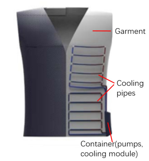
Figure 1.
Cooling system for garment.
2.1. Model of Cooling System
The models of the traditional cooling system (with continuous flow patterns) and the proposed bio-inspired system (with discontinuous pulsation flow patterns) are shown in Figure 2. The serpentine-shaped pipe design is one of the most commonly used designs for traditional tubular cooling systems. It provides a large area of contact surface for the pipe and heating source in a limited volume and the implementation of the pipe is simple. The serpentine pipe is widely applied to car radiators, domestic heaters and power-plant cooling systems, etc. The model of the serpentine pipe for the continuous-flow system is shown in Figure 2. The fluid is propelled by the pump and flows through the serpentine pipe, which has a heating pad underneath it. The system works in the following way: the heat is generated from the heating pad. Then it transfers to the fluid inside the serpentine pipe due to the conduction effect and the fluid carries the heat into a heat-exchanging cooling module (water block). The cooled fluid returns to the water pump and restarts another cycle of cooling. There are challenges remaining for this traditional system: that the cooling efficiency mainly depends on the material of pipe and coolant. Another challenge is that the cooling effect along the serpentine pipe is not equally distributed because the coolant fluid is heated up by the heating source, which leads to large temperature difference at the inlet and outlet of the pipe. The fluid temperature at the end of the pipe is significantly higher than the fluid temperature at the beginning of the pipe, which means the cooling efficiency towards the end of the pipe is lower than at its beginning. The proposed discontinuous-pulsation flow system is inspired by the blood circulation systems of humans and animals, in which the heart pumps the blood as a pulsation flow into different arteries. The model of the proposed system is shown in Figure 2b. Instead of a serpentine pipe, the model consists of five parallel pipes with valves at the beginning of each pipe. Each pipe is connected to the same central inlet and outlet. The valves are turned on sequentially so that the fluid can only flow through one pipe at a time, i.e., in a ‘scanning’ or ‘sweeping’ manner. The overall flowrate of the main inlet and outlet is measured and set to be the same as the flowrate of the continuous system. As shown in Figure 3, the blue line is the flow rate of the continuous system, and the orange line is the flow rate of the discontinuous system. There are some differences in the flow rate of the two systems, which are caused by the on–off switch action of the valves in the discontinuous system. However, the error is in an acceptable range which will not affect the temperature result.
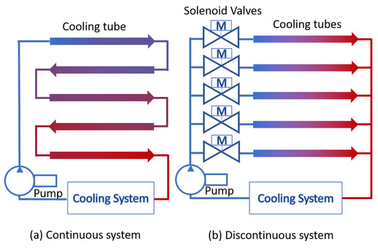
Figure 2.
Models for traditional and proposed systems.
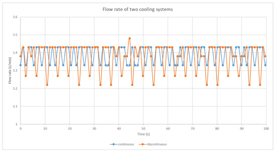
Figure 3.
Flow rate of the continuous and discontinuous cooling system.
In the proposed system, the temperature of the fluid at the beginning of each pipe is evenly distributed, as shown in Figure 2b, and, thus, the efficiency of the cooling process is increased. The main drawback of the proposed method is that it requires a valve for each pipe to control and generate a discontinuous-pulsation flow, which means more components are integrated into the garments system and influence the mobility of the user. Given that, a ferrofluid-based micro-valve is proposed in this work to minimise the weight and size of the cooling system for a garment. The proposed method significantly improves the cooling efficiency. With the ferrofluid valve implemented, it provides the potential for the system to be integrated to a garment with acceptable weight and higher efficiency. Experiments were carried out to validate and analyze the cooling efficiency of the proposed discontinuous-flow method and the traditional continuous-flow method. In addition, a finite-element-based computational fluid dynamics (CFD) model was developed, for future study, to simulate the influence of valves on fluid flows.
2.2. Model of Ferrofluid Valve
This paper proposes a ferrofluid valve which is actuated by an external magnetic field produced by coils. The diagrammatic representation of the proposed ferrofluid valve is shown in Figure 4. A permanent magnet is placed beneath the tube to absorb the ferrofluid and maintain its fixed position. A electromagnetic actuator is put on the top of the tube to generate a controllable magnetic field. When there is no excitation in the coil, as shown in Figure 4a, the ferrofluid is attracted by the permanent magnet, which opens the valve and allows the fluid to flow through. When there is an excitation, the coil generates a vertical magnetic field which actuates the ferrofluid to form into a closed valve and blocks the fluid flow, as shown in Figure 4b. Therefore, the ferrofluid valve can be manipulated to apply an effective valve action by manipulating the excitation of the coil. The parameters of the ferrofluid valve are shown in Table 1.
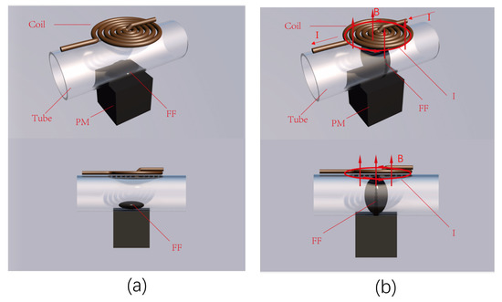
Figure 4.
Ferrofluid-valve model: (a) coil excitation off, valve on; (b) coil excitation on, valve off.

Table 1.
Parameters of ferrofluid.
3. Methods
3.1. Ferrofluid-Valve Design
The electromagnetic actuation for the ferrofluid valve is generated by the coil on the top side of the tube. An iron core is put in the middle of the coil to enhance and gather the magnetic flux. The coil is wound 500 times using the copper wires with a diameter of 0.1 mm. The diameter of the soft iron core and the coil is 2 mm. The coil excitation is controlled by a micro-controller ATmega1280 (MICROCHIP, Chicago, United states) and a power supply of 12 V. FEM-based electromagnetic models were carried out to calculate the magnetic-flux distribution generated by the coil. The software platform is COMSOL (version 5.6, COMSOL, Stockholm, Sweden) Multiphysics.
An experiment on controlling the shape of the ferrofluid valve was conducted and presented, for the future work, to build different shapes of valves which generate different types of flow and can potentially increase the cooling efficiency of the system.
3.2. Design of Cooling Systems
The piping and instrumentation diagram (P&ID) of the traditional continuous-flow system is shown in Figure 5a. The coolant fluid is pumped into the serpentine pipes and absorbs heat generated by the heating source (heating pad), which is used to simulate the heat from human body. The heated coolant then flows into the water block and Peltier module for cooling down and back to the pump for the next cooling cycle. A flowrate meter is attached to the main inlet of the pipe to measure the flowrate of the continuous flow.
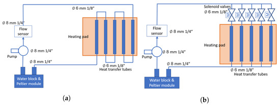
Figure 5.
P & ID of cooling systems. (a) P & ID of continuous system; (b) P & ID of discontinuous system.
The P&ID of the proposed discontinuous flow system is shown in Figure 5b. Instead of serpentine pipe, the proposed system uses five parallel pipes connected with ferrofluid valves. The coolant flows into each of the parallel pipes sequentially and then it is cooled by the water-block module for the next cooling cycle. These parallel pipes allow the coolant to have an evenly distributed temperature and, thus, a more efficient cooling effect. A flowrate meter is connected to the main inlet of the pipes to measure the overall flowrate of the proposed system and to keep the flowrate the same as that of the traditional continuous system.
3.3. Experimental Set-Up
The experimental set-up of the traditional and proposed cooling system were built based on the designs shown in Figure 5. The prototypes were designed to be wearable. However, in order to better compare the performance between the proposed prototype and the traditional system during the experimental development stage, the two cooling systems were implemented on a plywood board with a reference heating pad. The dimensions (length, width and height) of the plywood board are mm, respectively. A reference heating pad was implemented in the center of the plywood panel to measure the reference temperature to validate the cooling efficiency of the two cooling systems. The traditional continuous-flow system is implemented on the left-hand side of the board, as shown in Figure 6. A heating pad was implemented under the serpentine pipes to simulate human-body heat source. The proposed discontinuous-flow system was implemented on the right-hand side of the board with the ferrofluid valves implemented on each parallel pipe. A heating pad was put on the bottom of the parallel pipes as well to simulate a human-body heat source. The heating pads were installed with built-in thermistors which need to be wired and connected to a micro-controller to measure the temperature of the heating pad. A resistor = 100 k was connected in series with the thermistor of the heating pad. The resistance of the thermistor can be calculated by Equation (3).
where V is the voltage across the thermistor, and is the reference voltage . According to Steinhart and Hart equation [47], the temperature (Kelvin) of the thermistor can be derived as:
where K is set to be the common room temperature, stands for the constant of B-coefficient, and k represents the resistance of the thermistor at . The units of the temperature can by easily transferred by: (°C) + 273.15.
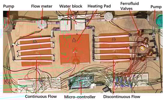
Figure 6.
Experimental set-up built on the polywood panel.
The ATmega1280 was used as the micro-controller to control the ferrofluid valves and to receive and save data from the sensors, including the flowrate meter sensor and the thermistors. The micro-controller ATmega1280 is driven by Arduino Software (IDE). The water pumps (Jadeshay LG/BL) generate a flow rate of 2 L/min with a rated power of 12 V. The water tanks were made of plastic bottles which store the water for the circulation of cooling system and eliminate the air bubbles of the system naturally. There were several different types of pipes and tubes used in building the cooling systems: Tubes with 6 mm inner diameter (ID) and outer diameter (OD) of 9 mm were used for connecting the flow sensors and water tank. Tubes with 8 mm ID and 11 mm OD were used for the connections of the water block. In addition, 6 mm ID Heat shrinking tubes were used for the main body of cooling system, heat transfer, as the walls of these tubes are thinner than most of the other plastic tubes on the market with reasonable prices. Each end of the tube was attached to the board firmly by hot glue, so that the tubes were contacted tightly with the heating pad to maximise the heat-transfer efficiency. The water-block module used was TEC1-12706 Thermoelectric (Hebei, China) Cooler. The flowrates of the two cooling systems were measured using a YF-S401 Flow sensor. The overall size of the discontinuous cooling system was (length, width and height) 270 mm × 160 mm × 12 mm. The overall weight (including permanent magnet and electromagnet) of each ferrofluid valve was 40 g.
3.4. FEM Simulation
The FEM model was built based on the software COMSOL multiphysics. In the simulation of the electromagnet, the magnetic vector potential was calculated by Equation (3).
where represents the magnetic permittivity, A stands for the magnetic vector potential, and represents the current density. The magnetic field H and the magnetic induction intensity B can be expressed as:
In the FEM simulation of permanent magnets, the magnetic field at the non-current region follows the conditions:
The magnetic scalar potential can be expressed as:
The magnetic induction intensity at the non-current region can be expressed as:
where M represents the magnetization factor, and stands for the permeability of vacuum. By substituting Equations (7) and (8) into (9), can be rewritten as:
The magnetic force applied on the ferrofluid can be calculated by the integration of the surface stress tensor. The stress tensor can be calculated as [9]:
where is the boundary normal pointing out from the ferrofluid, is the stress tensor of air. The value of the simulation parameters are shown in Table 1.
4. Implementation and Results
4.1. Ferrofluid Valve
FEM-based models were built to simulate and calculate the magnetic flux distribution of the ferrofluid valve, in order to predict and analyze the ferrofluid action under applied magnetic field. The simulation results were validated by the experimental results, that the geometry of the ferrofluid valve can be regulated by controlling the magnetic flux. As the size of the models is small, the effect of gravity is minor in comparison to the strong magnetic force.
The magnetic flux in the proposed ferrofluid valve is generated by both of the permanent magnets on the bottom side of tube and the coil on the top side. Figure 7a shows the calculated magnetic flux distribution inside the tube of the ferrofluid valve without excitation of the coil. The main density of magnetic flux is distributed on the bottom side of the tube, because of the permanent magnet, and, thus, the ferrofluid is adsorbed on the bottom of the tube, which is in-agreement with the experimental result shown in Figure 7b. The valve turns ‘on’ and allows fluid to pass through, where there is no excitation on the coil. According to the calculation result of the FEM model, the horizontal magnetic force on ferrofluid generated by a permanent magnet is 0.5 N, which makes the ferrofluid capable of withstanding a pressure of Pa.
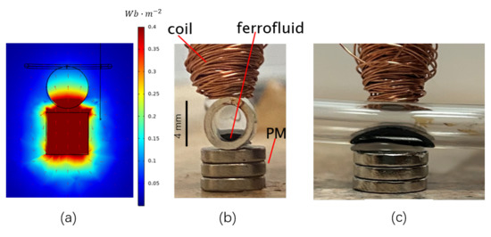
Figure 7.
Magnetic-flux distribution and ferrofluid shape without excitation. (a) Simulation model for magnetic flux. (b) Experimental shape of ferrofluid with non-optimised coils (front view). (c) Side view of valve.
In order to close the ferrofluid valve and block the fluid flow, an excitation of 0.9 A was injected into the coil to generate a vertical magnetic flux. As shown in Figure 8a, the magnetic flux is distributed evenly in the whole tube which actuates the ferrofluid to form as a closed valve, as shown in Figure 8b. The closed ferrofluid valve blocks the fluid flow through and the measured flowrate is reduced to below the minimum measurement range of the flowrate meter, which is close to 0 mL/min.
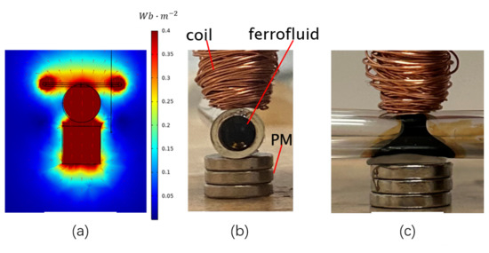
Figure 8.
Magnetic-flux distribution and ferrofluid shape with excitation. (a) Simulation model for magnetic flux. (b) Experimental shape of ferrofluid with non-optimised coils (front view). (c) Side view of valve.
Several more groups of simulation and experimental results with various combinations of permanent magnets were carried out to verify the assumption that the geometry of the ferrofluid is determined by the magnetic flux. As shown in Figure 9a and Figure 10a, the permanent magnet (rectangular shape) with different orientations generate different magnetic flux distributions. The geometry of the magnetic-flux distribution corresponds well with the shape of the ferrofluid shown in Figure 9b and Figure 10b. Permanent magnets in the experiments were positioned in the exact same location and orientation as the simulation models, which means the magnetic flux generated was in the same shape with the simulated results.
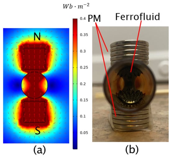
Figure 9.
Geometry analysis of ferrofluid (‘I’ shape). (a) Simulation model for magnetic flux. (b) Experimental shape of ferrofluid.
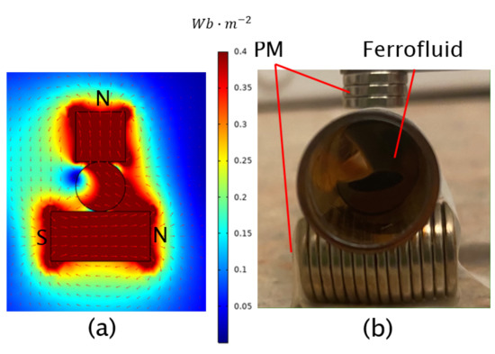
Figure 10.
Geometry analysis of ferrofluid. (a) Simulation model for magnetic flux. (b) Experimental shape of ferrofluid.
Similar results with more valve-shape designs are shown in Figure 11. These results confirm that the geometry of the ferrofluid valve can be manipulated to an exact shape by regulating the external magnetic-flux distribution. The ferrofluid valve with different shapes can generate a variety of flow patterns, which could potentially change the heat-transfer method (from conduct to convection) of the flow and, thus, increase the cooling efficiency.
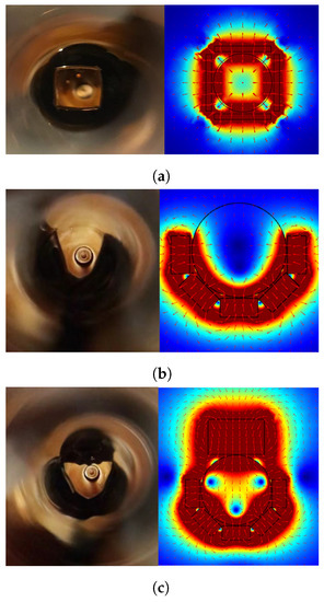
Figure 11.
Geometry control of ferrofluid. (a) Square-shape ferrofluid. (b) ‘U’-shape ferrofluid. (c) Triangle-shape ferrofluid.
4.2. CFD Analysis of Valve Actions
In this work, although the proposed cooling system was built empirically, CFD modelling was used to offer a first-order analysis of the flow behaviour during pulsation and continuous flow. This will provide important insights into the complicated thermal fluidic dynamics when “sweeping” management is applied on the cooling tubes. Furthermore, the switch action of the ferrofluid valve has a unique influence on the flow patterns of the cooling system. The CFD analysis of the valve on–off action can help to better understand how the ferrofluid-valve action influences the flow manner of the coolants. The CFD models are built to simulate the fluid dynamics when the valve is controlled to act in on or off status, as shown in Figure 12. The left-end pressure is adjusted at Pa, and 0 Pa is set to the right end. In Figure 12a, the valve is fully open and allows the fluid to flow through as a laminar flow, which transfers heat in a conduction way. In Figure 12b, when turning the valve partially off, the closing valve generates a counter flow as a vortex which can convert the laminar flow to turbulence. Therefore, the heat-transfer method changes from conduction to convection, which significantly increases the heat-transfer efficiency. Therefore, when using the proposed ferrofluid valves to generate a discontinuous pulsation flow to a cooling system, it also has the potential to increase the heat-transfer efficiency by creating turbulence in the flow.
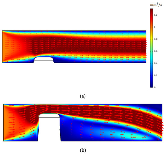
Figure 12.
CFD analysis insight of pulsation flow. (a) Laminar flow with valve turned ‘on’. (b) Turbulent flow with valve turned ‘off’.
4.3. Optimisation of the Sweeping Frequency
In this work, an empirical approach was used to figure out the optimal ‘sweeping’ frequency for the optimised cooling efficiency. The micro-controller was configured to generate different sweeping frequencies for the ferrofluid valves. To investigate the impact of the ‘sweeping’ frequency on cooling efficiency, pulsation periods ranging from 0.01 s to 5 s were used (frequency ranging from 0.2 Hz to 100 Hz). Three different pulsation durations (0.2 s, 1 s and 5 s) were selected to show the results of temperature measurement in real time, as shown in Figure 13. The figure shows the temperature difference, in other words, the cooling efficiency, between the reference heating pad and the two continuous- and discontinuous-flow systems. As the heating pad keeps generating heat with power supply, the measured temperature increases with time. The temperature difference between the proposed discontinuous system and the reference heating pad is shown in red color in Figure 13, and the temperature difference between the reference pad and the continuous system is shown in blue color. The maximum temperature difference between the discontinuous system and the reference is around 3 °C with 1 s pulsation time. The maximum temperature difference between the continuous system and the reference is 2 °C, which is not frequency-dependent. It is obvious that the temperature difference, which stands for the cooling efficiency, of the proposed discontinuous system is greater than that of the traditional continuous system. This confirms that the proposed cooling method can increase the cooling efficiency compared with the traditional method.
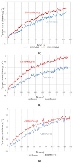
Figure 13.
Sweeping—period influence on the temperature difference of two cooling systems. (a) 0.2 s pulsation period; (b) 1 s pulsation period; (c) 5 s pulsation period.
In order to understand the influence of the sweeping frequency on the cooling efficiency, an average temperature difference between the proposed discontinuous system and both the continuous system and reference temperature was measured and is shown in Figure 14, where the sweeping frequency ranges from 0.2 Hz to 100 Hz. The data was collected and analyzed from the average temperature at 7 min of the measurement time. The temperature difference between the proposed system and the reference heating pad is plotted in red color, and the temperature difference between the continuous system and the proposed system is plotted in blue color. It can be seen in the figure that the temperature difference increases as the sweeping frequency increasing from 0.2 Hz to 1 Hz. The temperature difference then returns to the same level, with 0.5 Hz sweeping frequency when the frequency increases to 100 Hz. This is because, on the one hand, when the switching frequency is too low, the proposed system works as a continuous system with only one valve on and all the other valves off. On the other hand, when the frequency is too high, the proposed system works as a continuous system with all valves on. Therefore, the cooling efficiency of the proposed discontinuous system is similar to the continuous cooling system. The results of this empirical approach reveal that the optimal sweep frequency for this proposed prototype is around 1 Hz.
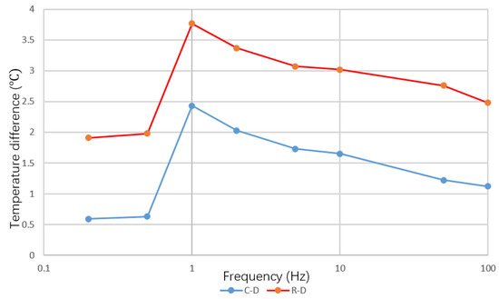
Figure 14.
Temperature difference between cooling systems and reference against sweeping frequency.
5. Discussion
The proposed bio-inspired cooling system shows a better cooling efficiency than that of the traditional continuous system. According to the previous data, the optimised sweeping frequency for this particular prototype is 1 Hz. Figure 15 shows an overall comparison of the cooling efficiency of different systems over the measurement period of 7 min. The temperature data is the averaged temperature of several repeated experiments, in order to reduce the system errors of measurement. The temperature of the reference heating pad is plotted in green color. It is increasing over time due to the Joule effect on heating. The proposed system and the traditional system are plotted in red and blue color, respectively. As shown in Figure 15, both systems exhibit a lower temperature over time than that of the reference heating pad, which illustrates that both the systems absorb heat from the heat source effectively. The temperature of the traditional cooling system is mostly the same as the reference heating pad in the first 50 s of measuring time. Then, the traditional system starts to cool down the temperature by 1.5 °C after 7 min of the cooling process, compared with the reference heating temperature. However, the proposed system starts to cool down the temperature at the beginning of the measurement and the temperature is reduced by 3.5 °C at 7 min, compared with the reference temperature. The proposed cooling system shows not only a quicker cooling response, but also an increased cooling efficiency overall, compared with the traditional continuous-flow system. In order to validate the influence of the switching valves, a measurement with all valves turned on was carried out, which is equivalent to removing all the valves in the discontinuous system. The result is shown in Figure 16. The blue line is the temperature of the continuous system, the green line is the reference temperature, and the red line is the temperature of the discontinuous system. The result shows that the discontinuous system exhibits an even worse cooling efficiency than that of the continuous system when all valves are turned on or removed. This is because the overall flow rate of the discontinuous system is evenly distributed into each of the five channels, which significantly reduces the Reynold number of each channel.
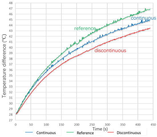
Figure 15.
Temperature of all modules.
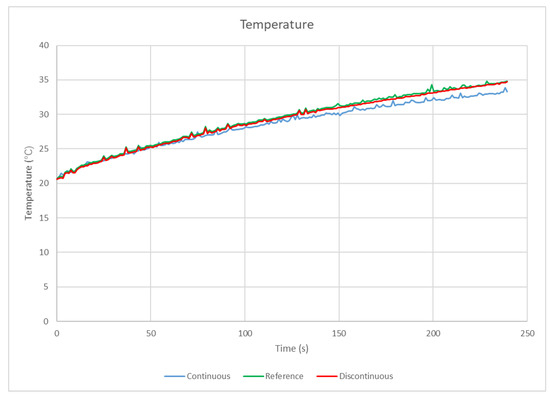
Figure 16.
Temperature of all modules with all valves turning on.
The proposed bio-inspired cooling method gives a more evenly distributed temperature on the cooling pipes and, thus, results in a more efficient cooling effect. Moreover, the discontinuous-pulsation flow can generate a large sudden flow rate which leads to sudden change in Reynold number and can easily create turbulence to enhance the heat-transfer efficiency. Furthermore, as shown in the CFD simulation results, the on–off switching dynamics of the ferrofluid valves can also have the potential to create counter flow and vortex and, thus, create turbulence to enhance the heat-transfer efficiency.
This prototype outperforms the typical cooling technology in terms of cooling efficiency. However, challenges remain in turning the prototype into a working garment. The first difficulty is that an individualized garment demands a portable and energy-efficient technology. This work only looked at cooling efficiency; further research on power use is needed in the future. The second problem is that the equipments and components for an individualized garment must be minimised. In the future, the optimised component should be used.
6. Conclusions
This work proposes a bio-inspired discontinuous-pulsation flow system for the thermal management of the design of personal garments. A prototype was presented to demonstrate the higher cooling efficiency of the proposed system over that of the traditional continuous flow method. In order to reduce the bulkiness caused by the valves added in the proposed system, a ferrofluid micro-valve was proposed to control the sweeping frequency of the discontinuous flow, whilst the weight of the system can be readily reduced to an acceptable level for a garment. It is envisaged that the proposed system can be easily integrated into a garment for regulating personal temperature. It has the potential to apply both cooling and warming effects by infusing fluid with different temperatures into the system. Thus, based on our findings, future work may explore the developments of highly flexible management of the temperature for individualized requirements.
Author Contributions
Conceptualization, P.L. and J.T.; methodology, J.T. and P.L.; software, J.T.; validation, J.T. and P.L.; formal analysis, J.T.; investigation, J.T. and P.L.; resources, P.L.; data curation, J.T. and P.L.; writing—original draft preparation, J.T.; writing—review and editing, P.L. and J.T.; visualization, J.T. and P.L.; supervision, P.L.; project administration, P.L.; funding acquisition, P.L. All authors have read and agreed to the published version of the manuscript.
Funding
This work is funded by the Engineering and Physical Sciences Research Council (EPSRC), Ref. EP/T006382/1.
Data Availability Statement
Not applicable.
Acknowledgments
The authors gratefully acknowledge the funding support by the the Engineering and Physical Sciences Research Council (EPSRC) and the experimental work prepared by Geoffroy D’Haussy.
Conflicts of Interest
The authors declare no conflict of interest.
Abbreviations
The following abbreviations are used in this manuscript:
| ID | Inner diameter |
| OD | Outer diameter |
| P&ID | Piping and instrumentation diagram |
| FEM | Finite element method |
| LCG | Liquid cooling garment |
| CFD | Computational fluid dynamics |
References
- Luo, M.; Arens, E.; Zhang, H.; Ghahramani, A.; Wang, Z. Thermal comfort evaluated for combinations of energy-efficient personal heating and cooling devices. Build. Environ. 2018, 143, 206–216. [Google Scholar] [CrossRef]
- Mokhtari Yazdi, M.; Sheikhzadeh, M. Personal cooling garments: A review. J. Text. Inst. 2014, 105, 1231–1250. [Google Scholar] [CrossRef]
- Bo-an, Y.; Yi-Lin, K.; Yi, L.; Chap-Yung, Y.; Qing-wen, S. Thermal regulating functional performance of PCM garments. Int. J. Cloth. Sci. Technol. 2004, 16, 84–96. [Google Scholar] [CrossRef]
- Bartkowiak, G.; Dąbrowska, A.; Włodarczyk, B. Construction of a garment for an integrated liquid cooling system. Text. Res. J. 2015, 85, 1809–1816. [Google Scholar] [CrossRef]
- Taylor, C.E.; Lau, S.F. Thermo-Voltaic Personal Cooling/Heating Device. US Patent 6,125,636, 3 November 2000. [Google Scholar]
- Ernst, T.C. Design, Fabrication and Testing of a Wearable Cooling System. Ph.D. Thesis, Georgia Institute of Technology, Atlanta, GA, USA, 2005. [Google Scholar]
- Gao, C.; Kuklane, K.; Wang, F.; Holmér, I. Personal cooling with phase change materials to improve thermal comfort from a heat wave perspective. Indoor Air 2012, 22, 523–530. [Google Scholar] [CrossRef] [PubMed]
- Robinson, P.J. On the definition of a heat wave. J. Appl. Meteorol. Climatol. 2001, 40, 762–775. [Google Scholar] [CrossRef]
- Anderson, G.B.; Bell, M.L. Heat waves in the United States: Mortality risk during heat waves and effect modification by heat wave characteristics in 43 US communities. Environ. Health Perspect. 2011, 119, 210–218. [Google Scholar] [CrossRef]
- Smoyer-Tomic, K.E.; Kuhn, R.; Hudson, A. Heat wave hazards: An overview of heat wave impacts in Canada. Nat. Hazards 2003, 28, 465–486. [Google Scholar] [CrossRef]
- Perez, S.A.; Charles, J.B.; Fortner, G.W.; Hurst, V.; Meck, J.V. Cardiovascular effects of anti-G suit and cooling garment during space shuttle re-entry and landing. Aviat. Space Environ. Med. 2003, 74, 753–757. [Google Scholar]
- Meng, Y.; Zhang, Z.; Wu, H.; Wu, R.; Wu, J.; Wang, H.; Pei, Q. A cascade electrocaloric cooling device for large temperature lift. Nat. Energy 2020, 5, 996–1002. [Google Scholar] [CrossRef]
- Hong, S.; Gu, Y.; Seo, J.K.; Wang, J.; Liu, P.; Meng, Y.S.; Xu, S.; Chen, R. Wearable thermoelectrics for personalized thermoregulation. Sci. Adv. 2019, 5, eaaw0536. [Google Scholar] [CrossRef] [PubMed]
- Teunissen, L.P.; Wang, L.C.; Chou, S.N.; Huang, C.h.; Jou, G.T.; Daanen, H.A. Evaluation of two cooling systems under a firefighter coverall. Appl. Ergon. 2014, 45, 1433–1438. [Google Scholar] [CrossRef] [PubMed]
- Yifen, Q.; Jiang, N.; Wei, W.; Zhang, G.; Baoliang, X. Heat transfer of heat sinking vest with phase-change material. Chin. J. Aeronaut. 2011, 24, 720–725. [Google Scholar]
- Mokhtari Yazdi, M.; Sheikhzadeh, M.; Dabirzadeh, A.; Chavoshi, E. Modeling the efficiency and heat gain of a phase change material cooling vest: The effect of ambient temperature and outer isolation. J. Ind. Text. 2016, 46, 436–454. [Google Scholar] [CrossRef]
- Gao, C.; Kuklane, K.; Holmér, I. Cooling vests with phase change material packs: The effects of temperature gradient, mass and covering area. Ergonomics 2010, 53, 716–723. [Google Scholar] [CrossRef] [PubMed]
- Kou, Y.; Sun, K.; Luo, J.; Zhou, F.; Huang, H.; Wu, Z.S.; Shi, Q. An intrinsically flexible phase change film for wearable thermal managements. Energy Storage Mater. 2021, 34, 508–514. [Google Scholar] [CrossRef]
- Zhang, H.; Ly, K.C.; Liu, X.; Chen, Z.; Yan, M.; Wu, Z.; Wang, X.; Zheng, Y.; Zhou, H.; Fan, T. Biologically inspired flexible photonic films for efficient passive radiative cooling. Proc. Natl. Acad. Sci. USA 2020, 117, 14657–14666. [Google Scholar] [CrossRef]
- Bartkowiak, G.; Dabrowska, A.; Marszalek, A. Assessment of an active liquid cooling garment intended for use in a hot environment. Appl. Ergon. 2017, 58, 182–189. [Google Scholar] [CrossRef]
- Cao, H.; Branson, D.H.; Peksoz, S.; Nam, J.; Farr, C.A. Fabric selection for a liquid cooling garment. Text. Res. J. 2006, 76, 587–595. [Google Scholar] [CrossRef]
- Nyberg, K.L.; Diller, K.R.; Wissler, E.H. Model of human/liquid cooling garment interaction for space suit automatic thermal control. J. Biomech. Eng. 2001, 123, 114–120. [Google Scholar] [CrossRef]
- Xu, X. Multi-loop control of liquid cooling garment systems. Ergonomics 1999, 42, 282–298. [Google Scholar] [CrossRef]
- Luk, P.C.; Tang, J. Wearable Bio-Inspired Pulsating Flow Cooling for Live Garments. In Proceedings of the 2022 IEEE International Instrumentation and Measurement Technology Conference (I2MTC), Ottawa, ON, Canada, 16–19 May 2022; pp. 1–6. [Google Scholar]
- Olaru, R.; Petrescu, C.; Hertanu, R. A novel double-action actuator based on ferrofluid and permanent magnets. J. Intell. Mater. Syst. Struct. 2012, 23, 1623–1630. [Google Scholar] [CrossRef]
- Garg, H.; Mehta, J.; Kumar, R. Performance study of magnetic cooling system using kerosene based ferrofluid under magnetic field effect. In Proceedings of the 2015 2nd International Conference on Recent Advances in Engineering & Computational Sciences (RAECS), Chandigarh, India, 21–22 December 2015; pp. 1–5. [Google Scholar]
- Kim, J.H.; Seo, H.S.; Kim, Y.J. Thermal-flow characteristics of ferrofluids in a rotating eccentric cylinder under external magnetic force. Micromachines 2018, 9, 457. [Google Scholar] [CrossRef] [PubMed]
- Özbey, A.; Karimzadehkhouei, M.; Yalçın, S.E.; Gozuacik, D.; Koşar, A. Modeling of ferrofluid magnetic actuation with dynamic magnetic fields in small channels. Microfluid. Nanofluid. 2015, 18, 447–460. [Google Scholar] [CrossRef]
- Mehta, J.S.; Kumar, R.; Kumar, H.; Garg, H. Numerical Investigation and Comparison of Thermal Performance of Ferrofluid in Different Closed Loop Configurations. In Proceedings of the Journal of Physics: Conference Series. IOP Publishing, Kurukshetra, India, 18–22 February 2019; Volume 1240, p. 012056. [Google Scholar]
- Finlayson, B. Modeling a ferrofluid in a rotating magnetic field. In Proceedings of the COMSOL Users’ Conference, Boston, MA, USA, 4–6 October 2007. [Google Scholar]
- Mateev, V.; Terzova, A.; Marinova, I. Design analysis of electromagnetic actuator with ferrofluid. In Proceedings of the 2014 18th International Symposium on Electrical Apparatus and Technologies (SIELA), Bourgas, Bulgaria, 29–31 May 2014; pp. 1–4. [Google Scholar]
- Liu, K.; Han, L.; Tang, P.; Yang, K.; Gan, D.; Wang, X.; Wang, K.; Ren, F.; Fang, L.; Xu, Y.; et al. An anisotropic hydrogel based on mussel-inspired conductive ferrofluid composed of electromagnetic nanohybrids. Nano Lett. 2019, 19, 8343–8356. [Google Scholar] [CrossRef]
- Wang, W.; Timonen, J.V.; Carlson, A.; Drotlef, D.M.; Zhang, C.T.; Kolle, S.; Grinthal, A.; Wong, T.S.; Hatton, B.; Kang, S.H.; et al. Multifunctional ferrofluid-infused surfaces with reconfigurable multiscale topography. Nature 2018, 559, 77–82. [Google Scholar] [CrossRef] [PubMed]
- Giwa, S.; Sharifpur, M.; Goodarzi, M.; Alsulami, H.; Meyer, J. Influence of base fluid, temperature, and concentration on the thermophysical properties of hybrid nanofluids of alumina–ferrofluid: Experimental data, modeling through enhanced ANN, ANFIS, and curve fitting. J. Therm. Anal. Calorim. 2021, 143, 4149–4167. [Google Scholar] [CrossRef]
- Li, C.; Wu, S.; Luk, P.C.K.; Gu, M.; Jiao, Z. Enhanced bandwidth nonlinear resonance electromagnetic human motion energy harvester using magnetic springs and ferrofluid. IEEE/ASME Trans. Mechatron. 2019, 24, 710–717. [Google Scholar] [CrossRef]
- Ravaud, R.; Lemarquand, G.; Lemarquand, V. Mechanical properties of ferrofluid applications: Centering effect and capacity of a seal. Tribol. Int. 2010, 43, 76–82. [Google Scholar] [CrossRef]
- Rogge, H.; Erbe, M.; Buzug, T.M.; Lüdtke-Buzug, K. Simulation of the magnetization dynamics of diluted ferrofluids in medical applications. Biomed. Tech. Eng. 2013, 58, 601–609. [Google Scholar] [CrossRef]
- Nepomnyashchaya, E.; Velichko, E.; Pleshakov, I.; Aksenov, E.; Savchenko, E. Investigation of ferrofluid nanostructure by laser light scattering: Medical applications. In Proceedings of the Journal of Physics: Conference Series, Torino, Italy, 24–26 October 2016; Volume 841, p. 012020. [Google Scholar]
- Chhattal, M.; Tonggang, L.; Kun, Y.; Xin, L.; Guangsheng, L. Development of a tribotester for investigation of ferrofluids lubrication performance on the thrust pad bearing. Tribol. Trans. 2020, 63, 1095–1102. [Google Scholar] [CrossRef]
- Raj, K.; Moskowitz, B.; Casciari, R. Advances in ferrofluid technology. J. Magn. Magn. Mater. 1995, 149, 174–180. [Google Scholar] [CrossRef]
- Ravaud, R.; Pinho, M.; Lemarquand, G.; Dauchez, N.; Génevaux, J.M.; Lemarquand, V.; Brouard, B. Radial stiffness of a ferrofluid seal. IEEE Trans. Magn. 2009, 45, 4388–4390. [Google Scholar] [CrossRef][Green Version]
- Ganguly, R.; Gaind, A.P.; Sen, S.; Puri, I.K. Analyzing ferrofluid transport for magnetic drug targeting. J. Magn. Magn. Mater. 2005, 289, 331–334. [Google Scholar] [CrossRef]
- Sheikholeslami, M.; Arabkoohsar, A.; Khan, I.; Shafee, A.; Li, Z. Impact of Lorentz forces on Fe3O4-water ferrofluid entropy and exergy treatment within a permeable semi annulus. J. Clean. Prod. 2019, 221, 885–898. [Google Scholar] [CrossRef]
- Kurtoğlu, E.; Bilgin, A.; Şeşen, M.; Yıldız, M.; Acar, H.F.Y.; Koşar, A. Ferrofluid actuation with varying magnetic fields for micropumping applications. Microfluid. Nanofluid. 2012, 13, 683–694. [Google Scholar] [CrossRef]
- Doganay, S.; Cetin, L.; Ezan, M.A.; Turgut, A. A rotating permanent magnetic actuator for micropumping devices with magnetic nanofluids. J. Micromech. Microeng. 2020, 30, 075012. [Google Scholar] [CrossRef]
- Liu, B.; Zhang, Z.; Yang, J.; Yang, J.; Li, D. A rotary ferrofluidic vane micropump with C shape baffle. Sens. Actuators Chem. 2018, 263, 452–458. [Google Scholar] [CrossRef]
- Rana, K.P.S.; Kumar, V.; Dagar, A.K.; Chandel, A.; Kataria, A. FPGA implementation of steinhart–hart equation for accurate thermistor linearization. IEEE Sens. J. 2018, 18, 2260–2267. [Google Scholar] [CrossRef]


Publisher’s Note: MDPI stays neutral with regard to jurisdictional claims in published maps and institutional affiliations. |
© 2022 by the authors. Licensee MDPI, Basel, Switzerland. This article is an open access article distributed under the terms and conditions of the Creative Commons Attribution (CC BY) license (https://creativecommons.org/licenses/by/4.0/).