Article

Unconventional Energy from an Electric Impulse Heater Combined with a Wind Turbine

1
Renewable Energy Institute of NAS of Ukraine, Hnat Khotkevich Street, 20A, 02094 Kyiv, Ukraine
2
Igor Sikorsky Kyiv Polytechnic Institute, National Technical University of Ukraine, 37 Peremohy Av., 03056 Kyiv, Ukraine
3
Department of Mechanical and Engineering Agroecosystems, Polissia National University, Staryi Blvd., 7, 10008 Zhytomyr, Ukraine
4
Department of Technology, Institute of Energy and Technical Safety, Jacob of Paradyz University, 52 Chopina Street, 66-400 Gorzow Wielkopolski, Poland
5
Department of Renewable Energy Engineering, West Pomeranian University of Technology in Szczecin, 1 Papieza Pawla VI Street, 71-459 Szczecin, Poland
6
Institute of Technology and Life Sciences—National Research Institute, Falenty, Al. Hrabska 3, 05-090 Raszyn, Poland
7
Department of Technology, Branch Poznan, 67 Biskupinska Street, 60-463 Poznan, Poland
*
Author to whom correspondence should be addressed.
Energies 2022, 15(23), 8863; https://doi.org/10.3390/en15238863
Submission received: 27 October 2022 / Revised: 14 November 2022 / Accepted: 21 November 2022 / Published: 24 November 2022

Abstract

:
The widespread use of wind power plants can provide full or partial energy supply to the consumer, taking into account certain investments and the instability of energy production. Modern wind energy technology involves the conversion of mechanical energy of the wind flow into electrical energy with subsequent conversion, at the request of the consumer, into thermal energy. In addition, the unprocessed use of the low-potential part of the wind flow, characterized by non-uniformity and randomness of its reception for the purpose of supplying heat to the recipient, requires new approaches to solving this problem. Bench experimental studies of this heater confirmed the adequacy of the mathematical model: within an hour, the temperature increase of the heater core changed from 22 °C to 36 °C at a voltage of 66 V and the number of pulses entering the heater coil was (15–17) discharges, which corresponds to the values of the mathematical expectation of the wind speed of (4–5.2) m∙s−1 in the range of wind speed (4–8) m∙s−1. The scientific novelty of this work consists in the development of a mathematical model for the operation of an electric pulse heater, which made it possible to develop methodological provisions for determining its mode parameters and to estimate the temperature change of its elements at random wind speed.

1. Introduction

The energy strategy of any country is aimed at increasing the level of provision of inexpensive and affordable energy for production and the population [1,2]. It should also be noted that the cost of heat and electricity coming from traditional sources is constantly increasing compared to renewable energy sources [3,4,5]. Therefore, the use of wind turbines is effective [6,7]. The use of wind turbines can have a positive impact on the energy supply of the country [8,9]. However, the implementation of wind turbines requires significant financial costs [9,10]. Analysis of scientific publications shows that modern technologies for the use of wind energy involve the conversion of mechanical energy of the wind flow into electrical energy with further conversion into mechanical or thermal energy [11,12]. However, the stability of wind conditions has a significant impact on the quality of energy production by wind turbines [13,14]. In addition, the unprocessed use of the low-potential part of the wind flow, characterized by unevenness and randomness of its receipt for the needs of heat supply to the consumer, requires the search for new approaches to solving this problem [15,16]. In particular, it is proposed to use energy storage systems in compressed air to compensate for the instability of the wind situation [16], but such systems are of considerable complexity and size. Systems for converting the mechanical energy of the wind flow into thermal energy have become widespread [17,18]. However, such systems have a rather low overall coefficient of energy utilization in the wind, up to 30% [19].
The use of renewable energy is a promising solution to the environmental problems caused by the use of fossil fuels. The fact that these types of energy are sporadic can be overcome by using energy storage systems. The authors of [20] studied the integration of a system with a combined cooling, heating, and power cycle consisting of a gas turbine, an organic Rankine cycle, and an absorption cooling system. The results show that under design conditions, the system can generate 33.67 kW of electricity, 2.56 kW of cooling and 1.82 tons of hot water per day, with a round-trip energy efficiency of 53.94%. Sensitivity analysis showed that the parameters related to the gas turbine are the most important system parameters that can significantly change the system’s performance [20].
In recent years, there has been a growing interest in renewable energy sources, in particular wind energy for electricity generation. Scientists [21] have made several attempts to find a solution for the efficient use of wind energy. As a result of comprehensive research and extensive research on the subject, wind energy is now a widely exploited renewable energy source for electricity production. The main challenge for converting wind energy is to deal with the irregular nature of the wind. An overview of the wind energy conversion system was presented, highlighting its electrical and control aspects, including brief notes on aerodynamics and mechanical properties. The capacity of wind farms in the world, including India, was shown and discussed. The article analyzes the latest technology related to the wind power system and future research directions [21].
Significant progress has been made around the world in the transition to a sustainable society. Since 2007, annual investment in renewable energy has exceeded the combined investment in fossil and nuclear energy. However, in many developing countries, the balance is still in favor of conventional energy. An understanding of the barriers and drivers of this global imbalance in wind energy deployment in developing countries is presented through a systematic literature review and meta-analysis. In addition, different perspectives are identified to understand wind energy development from the original equipment manufacturer’s point of view. This is important because the sale of wind turbines is a practical component of the transition to a sustainable society. Factors affecting wind energy diffusion were identified and grouped into the following categories: economic, environmental, technical, technological, social, regulatory, political. A novel closed-loop feedback system was proposed as a conceptual framework for categorizing factors affecting wind energy diffusion into two types: factors related to wind energy demand and factors related to the mechanism of this change [22].
The use of wind energy is currently one of the priority directions of the world energy development, which allows to achieve: elimination of the energy instability of countries associated with energy crises; reducing the amount of harmful emissions generated in the process of using traditional energy carriers; preservation of energy reserves for future generations; increase in consumption of organic raw materials for non-energy needs.
One of the solutions is the use of electric pulse heaters. To create short pulses, it is advisable to use capacitive drives, the energy output time from which is (10−3–10−6) s [23].
Pulse electric heaters are not widely distributed today, but examples of their use in soldering devices are known [24]. Pulse power sources are widely used in various fields [25], but they are practically not used to power impulse electric heaters.
One of the reasons that hinder the use of electric pulse heating installations is the lack of appropriate mathematical models, which makes it impossible to estimate the currents that occur in the components of the heater. In addition, without understanding the discharge process in electric pulse installations, it is often impossible to select the parameters of chargers and capacitive storage devices. It is desirable to carry out such coordination so that charging and discharging are mutually independent, which relies on the control system of the pulse device. Most often, the control circuit disconnects the discharging unit from the charging unit during the discharging process.
In this work, the heater is not directly connected to the wind turbine, but through the storage element and the pulse converter, which is disconnected from the wind turbine at the time of connection.
The aim of the work is to develop a mathematical model of operation of a pulsed electric heater and to estimate the temperature changes of its elements at random wind speed.
The scientific novelty of the work consists in the development of a mathematical model of the operation of an electric pulse heater, which made it possible to develop methodological provisions for determining its mode parameters and to estimate the temperature change of its elements at random wind speed.

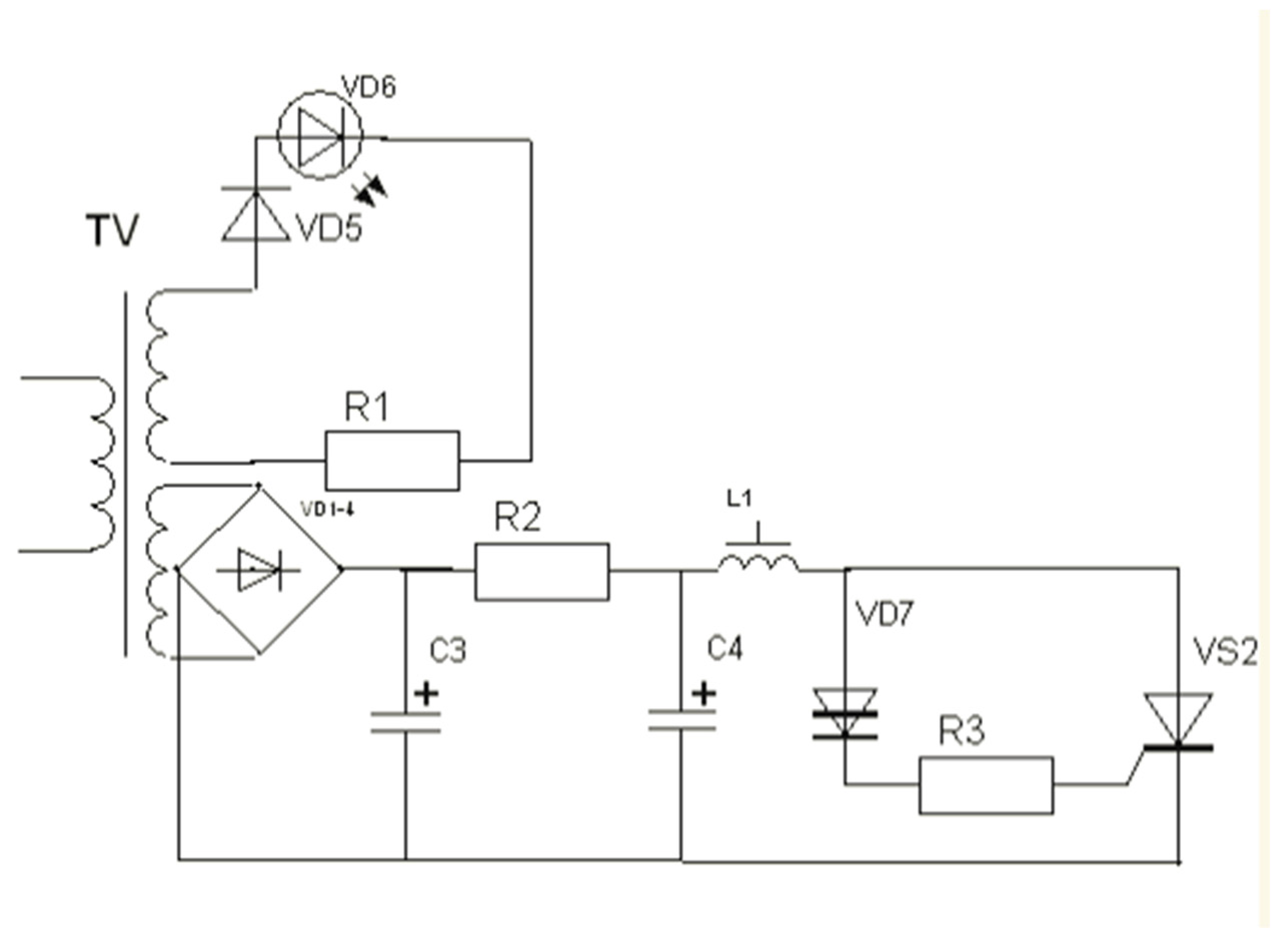
2. Materials and Methods

The study of the operation mode of the electric pulse heater with capacitive storage as part of an autonomous wind turbine was carried out by modeling using the Mathcad software package.
The structural diagram of the electric pulse heater with capacitive storage as part of an autonomous wind turbine is shown in Figure 1. The electric energy coming from the wind power plant is fed into the capacitive storage and upon reaching the specified voltage level, it is converted into a pulse and fed to the winding of the electric heater. Additionally, it is induced in the ferromagnetic core and the screen where it is converted into thermal energy.
Structurally, the heater consists of three elements: a ferromagnetic core in the form of a tube, on which a single-layer winding is wound, and this structure is placed in a tubular cylindrical screen connected to the core.
The operating mode of the system is as follows: the wind turbine charges the capacitive storage device to a predetermined voltage level. After that, the converter is activated and creates a pulse in the electric heater winding. The heater is structurally made in the form of a tubular ferromagnetic core, on which a single-layer winding (copper busbar) is wound and the whole structure is covered by a closed ferromagnetic tubular screen.
The used wind turbine has a classic structure: rotor, multiplier, synchronous generator. The operation process of the “wind power plant-electric pulse heater” system takes place in two stages: charging the storage tank through a three-phase rectifier to a given voltage level and discharge to the heater coil, and simultaneously disconnecting the capacity from the wind turbine in order to reduce the influence of the braking mode of the heater operation on the turbine.
The substitute scheme for the study of the operation mode of the electric pulse heater with capacitive storage is shown in Figure 2.
The initial system of differential equations has the form Equation (1):
{ L 1 d i 1 d t M 1 d i 2 d t M 2 d i 3 d t + i 1 ( R 1 + R k ) U c = 0 ; C d U c d t = i 1 ; L 2 d i 2 d t + M 1 d i 1 d t + i 2 R 2 = 0 ; L 3 d i 3 d t + M 2 d i 1 d t + i 3 R 3 = 0
Rewrite the system of Equation (1) in the following form Equation (2):
{ d i 1 d t = M 1 L 1 d i 2 d t + M 2 L 1 d i 3 d t i 1 R 1 + R k L 1 + U c L 1 ; d U c d t = i 1 1 C ; d i 2 d t = M 1 L 2 d i 1 d t i 2 R 2 L 2 d i 3 d t = M 2 L 3 d i 1 d t i 3 R 3 L 3
Replace the first row in the system of Equations in (2) with the last row in the system of Equation (2). Then, replace the fourth row in the system of Equation (2) in the first row of the system of Equation (2). After restoring the normal form and simplification, we will obtain a system of differential equations with the following form Equation (3):
{ d i 1 d t = L 2 L 3 L 1 L 2 L 3 + M 1 2 L 3 + M 2 2 L 2 U C ( R 1 + R k ) L 2 L 3 L 1 L 2 L 3 + M 1 2 L 3 + M 2 2 L 2 i 1 R 2 M 1 L 3 L 1 L 2 L 3 + M 1 2 L 3 + M 2 2 L 2 i 2 R 3 M 2 L 2 L 1 L 2 L 3 + M 1 2 L 3 + M 2 2 L 2 i 3 ; d i 2 d t = U C M 1 L 3 L 1 L 2 L 3 + M 1 2 L 3 + M 2 2 L 2 + M 1 ( R 1 + R k ) L 3 L 1 L 2 L 3 + M 1 2 L 3 + M 2 2 L 2 i 1 + R 2 M 1 2 L 3 R 2 ( L 1 L 2 L 3 + M 1 2 L 3 + M 2 2 L 2 ) L 2 ( L 1 L 2 L 3 + M 1 2 L 3 + M 2 2 L 2 ) i 2 + R 3 M 2 M 1 L 1 L 2 L 3 + M 1 2 L 3 + M 2 2 L 2 i 3 ; d i 3 d t = U C M 2 L 2 L 1 L 2 L 3 + M 1 2 L 3 + M 2 2 L 2 + M 2 ( R 1 + R k ) L 2 L 1 L 2 L 3 + M 1 2 L 3 + M 2 2 L 2 i 1 + R 2 M 1 M 2 L 1 L 2 L 3 + M 1 2 L 3 + M 2 2 L 2 i 2 + R 3 M 2 2 L 2 R 3 ( L 1 L 2 L 3 + M 1 2 L 3 + M 2 2 L 2 ) L 3 ( L 1 L 2 L 3 + M 1 2 L 3 + M 2 2 L 2 ) i 3 ; d U d t = i c C
In vector form, system (4)–(7) is written as:
x ˙ ( t ) = A · x ( t ) ,
for:
x ( t ) = ( i 1 ( t ) ,   i 2 ( t ) ,   i 3 ( t ) , U c ( t ) ) T
A = [ A 1 , 1 A 1 , 2 A 1 , 3 A 1 , 4 A 2 , 1 A 2 , 2 A 2 , 3   A 2 , 4 A 3 , 1 A 3 , 2 A 3 , 3 A 3 , 4 A 4 , 1 A 4 , 2 A 4 , 3 A 4 , 4 ]
for:
A 1 , 1 = ( R 1 + R k ) · L 2 · L 3 L 1 · L 2 · L 3 + M 1 2 · L 3 + M 2 2 · L 2 ,   A 1 , 2 = R 2 · M 1 · L 3 L 1 · L 2 · L 3 + M 1 2 · L 3 + M 2 2 · L 2 ,   A 1 , 3 = R 3 · M 2 · L 2 L 1 · L 2 · L 3 + M 1 2 · L 3 + M 2 2 · L 2 , A 1 , 4 = L 2 · L 3 L 1 · L 2 · L 3 + M 1 2 · L 3 + M 2 2 · L 2 , A 2 , 1 = M 1 · ( R 1 + R k ) · L 3 L 1 · L 2 · L 3 + M 1 2 · L 3 + M 2 2 · L 2 ,   A 2 , 2 = R 2 · M 1 2 · L 3 R 2 · ( L 1 · L 2 · L 3 + M 1 2 · L 3 + M 2 2 · L 2 ) L 2 · ( L 1 · L 2 · L 3 + M 1 2 · L 3 + M 2 2 · L 2 ) , A 2 , 3 = R 3 · M 2 · M 1 L 1 · L 2 · L 3 + M 1 2 · L 3 + M 2 2 · L 2 ,   A 2 , 4 = M 1 · L 3 L 1 · L 2 · L 3 + M 1 2 · L 3 + M 2 2 · L 2 , A 3 , 1 = M 2 · ( R 1 + R k ) · L 2 L 1 · L 2 · L 3 + M 1 2 · L 3 + M 2 2 · L 2 ,   A 3 , 2 = R 2 · M 1 · M 2 L 1 · L 2 · L 3 + M 1 2 · L 3 + M 2 2 · L 2 , A 3 , 3 = R 3 · M 2 2 · L 2 R 3 · ( L 1 · L 2 · L 3 + M 1 2 · L 3 + M 2 2 · L 2 ) L 3 · ( L 1 · L 2 · L 3 + M 1 2 · L 3 + M 2 2 · L 2 ) ,   A 3 , 4 = M 2 · L 2 L 1 · L 2 · L 3 + M 1 2 · L 3 + M 2 2 · L 2 , A 4 , 1 = 1 C ,     A 4 , 2 = 0 ,     A 4 , 3 = 0 ,     A 4 , 4 = 0 .
The initial conditions are as follows Equation (8):
( i 1 ( t = 0 ) i 2 ( t = 0 ) i 3 ( t = 0 ) U c ( t = 0 ) ) = ( 0 0 0 66 )
To solve the system, it is necessary to determine the values of inductance and resistance in accordance with the technological conditions.
The coil of the electric pulse heater is structurally made in the form of a solenoid, for the calculation of L1 Equation (9), the inductance of which the dependence [26] is adopted:
L 1 = μ 0 π ω 2 d e 4 a [ 1 4 3 π 1 α + 1 8 1 α 2 ]
where:
μ 0 = 4 π 10 7
α = a d
The inductance of the internal ferromagnetic core L2 and the external ferromagnetic shield L3 is determined by the expression [26] (12):
L = μ 0 l 2 π [ l n 2 l c r 1 ]
where:
c = r R
The value M1 and M2 is determined Equation (14) by the expression [26]:
M = μ 0 ω a 2 [ π 8 d 2 D ( q 1 + δ 2 8 q 3 + δ 4 64 q 5 ) ]
where
q 1 = 1 + 1 γ
q 3 = 1 γ 3
q 5 = 1 + 4 γ 5 5 γ 7
γ = D D 2 + 4 a 2
δ = d D
A comparison of other materials is planned in further studies.

3. Results and Discussions

The result of solving system Equation (6) is shown in Figure 3.
The thermal effect of the impulse Equation (20) on the heating process consists of several elements: the temperature from the winding θ1, which is transferred to the core by thermal conductivity, from the temperature of the impulse of the current induced in the core θ2 and the temperature on the screen θ3 of the heater:
Θ = f (θ1, θ2, θ3)
The heat flux from the action of the impulse can be estimated using the Joule–Lenz law Equation (21):
Q = I 2 R t
with the assumption that the pulse has a rectangular shape with an area equal to the area of the actual pulse shape. At the obtained values of currents, the estimation of thermal effect without taking into account the heating losses was Equation (22):
{ P 1 = 4.34 J P 2 = 0.48 J P 3 = 0.76 J
for one pulse of the heater operation, i.e., the heating is mainly due to the heat transfer from the winding to the core. The influence of the other two components is to counteract the decrease in heater temperature during the pause between pulses.
The temperature increase Equation (23) on the inner surface of the core is obtained from the Fourier equation and will be for a cylindrical surface [27]:
Δ θ = Q w 2 π l i = 1 n 1 λ i l n d 2 d 1  
The results of modeling and calculations have been verified in a full-scale bench experiment. Figure 4 shows the scheme of the pulse converter of the electric heater. The operation of the circuit is as follows: The input of the amplifying unit TV receives a signal from the wind turbine, rectifies the matrix VD1-4 and charges the capacitor C4. When the level sufficient for the breakdown of the dinistor VD7 opens the thyristor VS2, the current flows through the inductor L1 (heater winding).
By changing the voltage, it is possible to determine the time of reaching the limit of operation of the keys responsible for the start of discharging the capacitive storage device. The charging time of the capacitive storage tank of a stand-alone wind turbine up to certain technological limits using simulation modeling under stochastic changes in wind speed level is described in detail in [28]. Figure 5 shows graphs of the time taken to reach the limits of different thresholds of operation depending on the values of the mathematical expectation of wind speed when it changes in the range (4–8) m∙s−1.
The graphs have a linear character of change, which makes it possible to predict the value of operation even at higher wind speeds.
The pulse shape i1 in the experiment had the configuration shown in Figure 6. The amplitude value was 860 A, which corresponds to the calculated value with an error within 3%. The result of 3% is an acceptable result of research as it does not exceed the permissible limit in engineering calculations of 5–10%.
With the current value obtained from the model, the thermal effect was estimated Δθ = 0.79 °C for one minute of operation of the heater without taking into account the heating losses and the number of (15–17) discharges of pulses entering the coil (operating limit 66 V).
The thermal effect of core temperature during the bench experiment is shown in Figure 7.
The thermal effect of core during the experiment was approximately 1 °C per min, which is adequate to the calculated values.
The paper presents the results of research investigating the possibility of the technological process of electric pulse heating of a mock-up sample, not the final sample of the product.
In addition, a key role in improving the efficiency of energy harvesting in an unconventional way is played by triboelectric nanogenerators (MC-TENGs) to harvest energy in undesirable mechanical excitations. Copper MC-TENG devices proved to be the most effective design generating a maximum mode in the closed-circuit 4 V voltage range with a resistance of 10 GΩ. The proposed MC-TENG concept provides an effective method of obtaining electricity from low-frequency and low-amplitude oscillations, such as ocean waves, which is worth pointing out as a curiosity of scientific research [29].

4. Conclusions

(1)
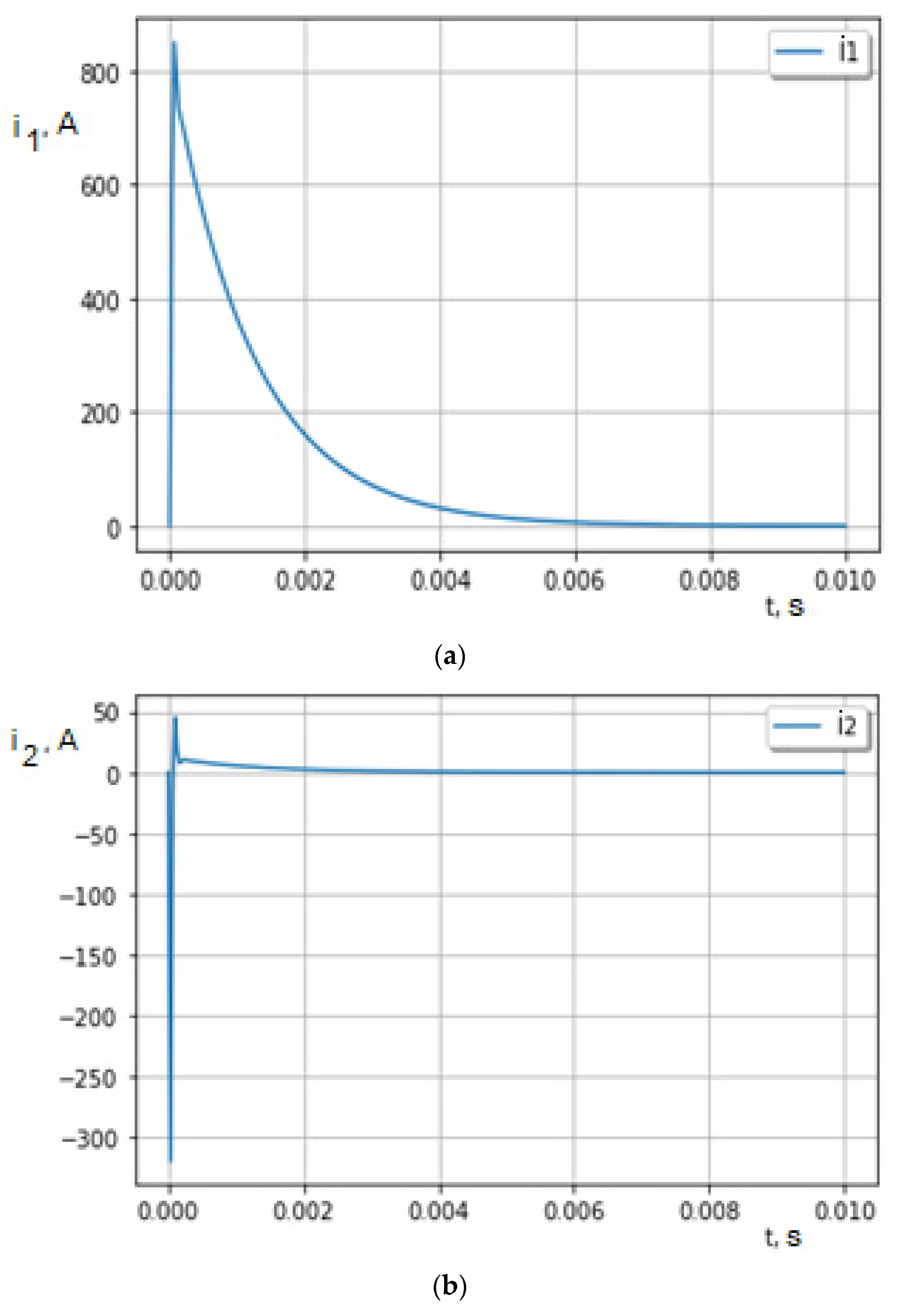
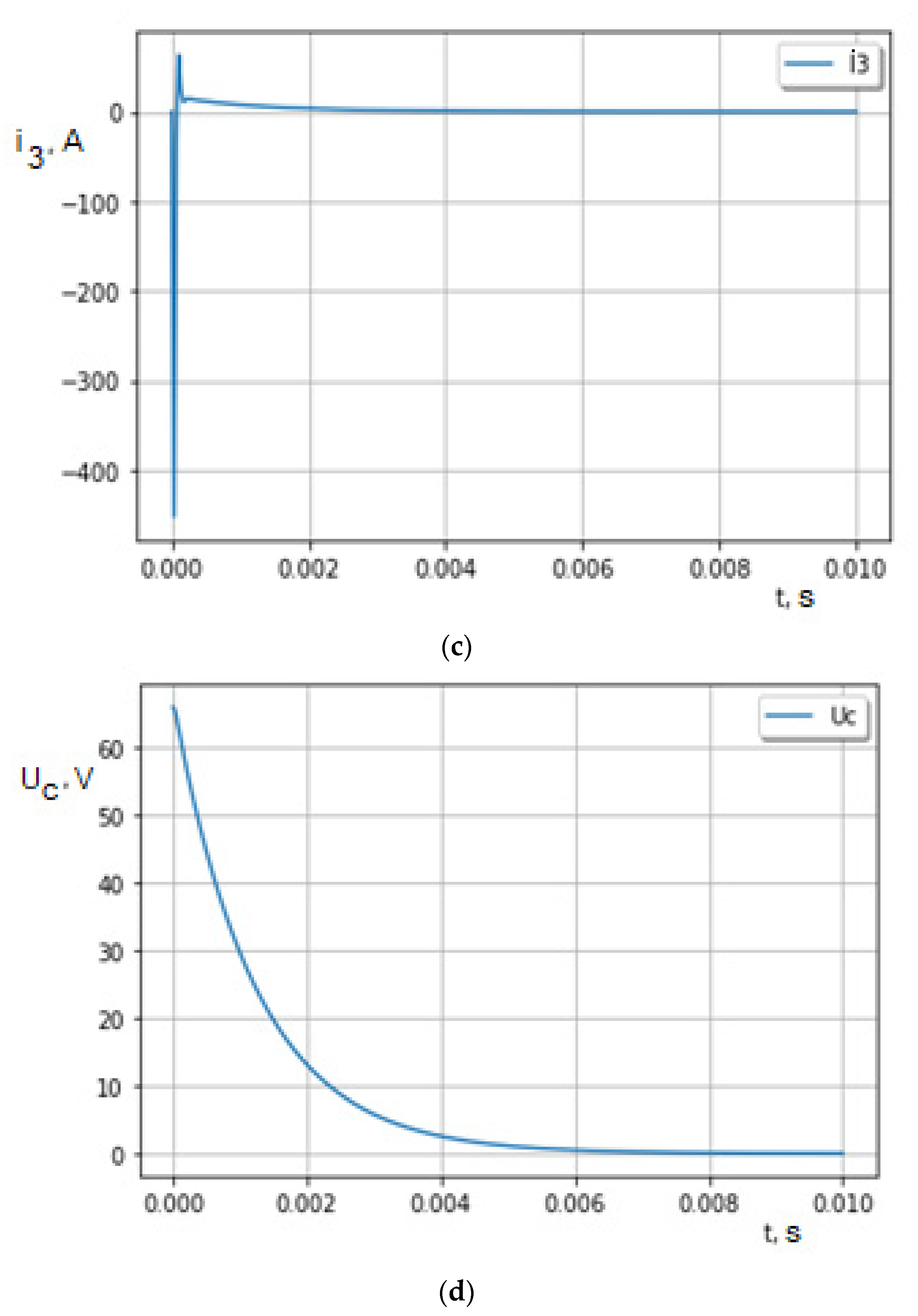
A mathematical model of the operation of an electric pulse heater was developed, which made it possible to determine the pulse currents in the coil (imax1 = 850A), the core (imax2 = 380A), and in the screen (imax3 = 530A), as well as to develop methodological provisions for evaluating the temperature change of its elements at a random wind speed.
(2)
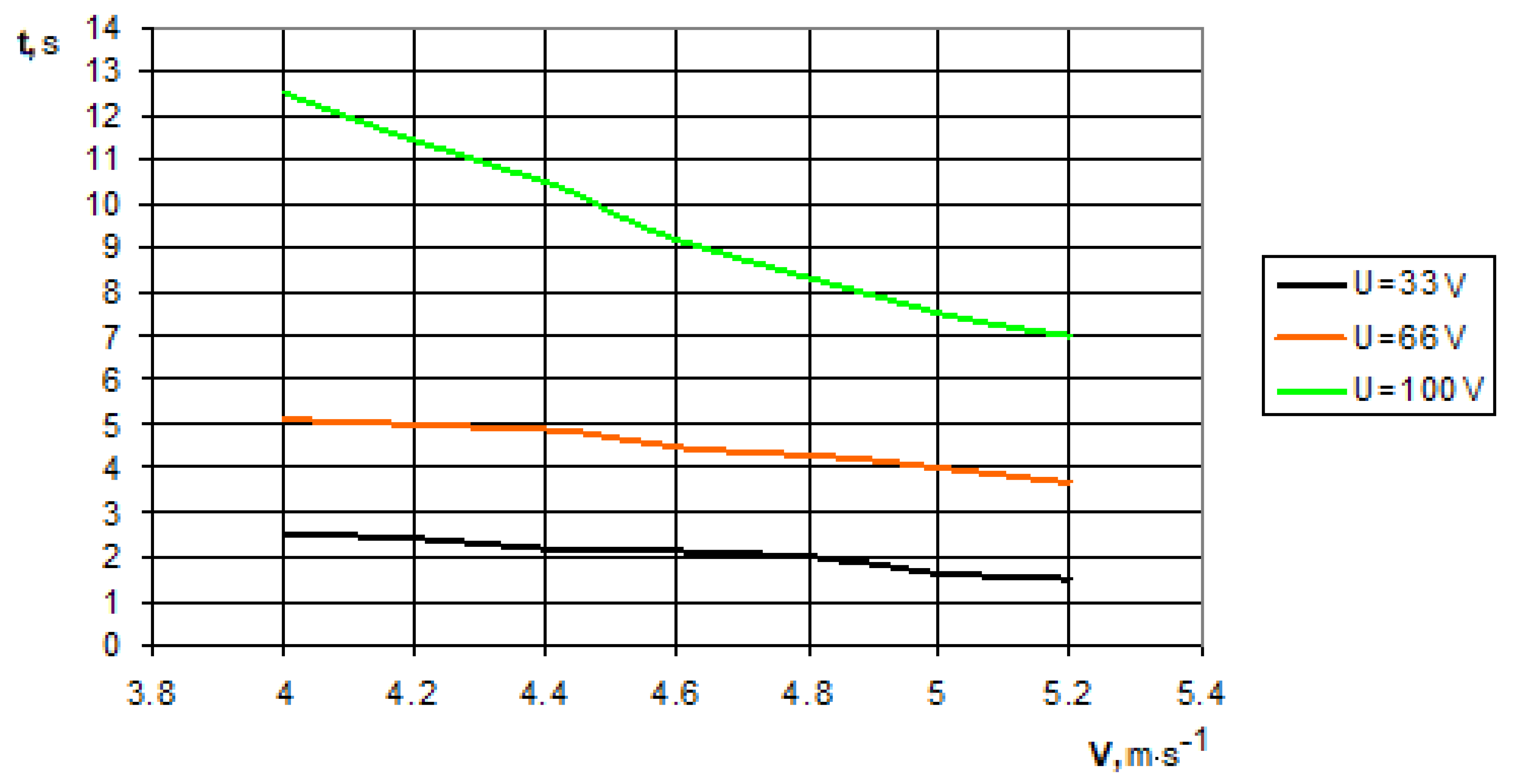
Bench experimental studies of the operation of the electric pulse heater were carried out, which confirmed the adequacy of the mathematical model for determining the currents in its constituent elements. It was established that, within an hour, the increase in the temperature of the heater core changed from 22 °C to 36 °C at a voltage of 66V and number of pulses entering the heater coil of (15–17) discharges, which corresponds to the values of the mathematical expectation of the wind speed of (4–5.2) m∙s−1 in the speed range wind (4–8) m∙s−1. The results were in satisfactory agreement with the calculated values. This model can be applied to other construction materials of the heater, which is expected in further research.

Author Contributions

Conceptualization, V.H., V.K., M.S., A.D., M.M., O.S. and S.K.; data curation, V.H., V.K., M.S., A.D., M.M., O.S. and S.K.; formal analysis, V.H., V.K., M.S., A.D., M.M., O.S. and S.K.; funding acquisition, A.K.; investigation, V.H., V.K., M.S., A.D., M.M., O.S., S.K., R.K., A.K., B.D. and G.W.; methodology, R.K., A.K., B.D. and G.W.; project administration, R.K., A.K. and G.W.; resources, R.K., A.K., B.D. and G.W.; software, V.H., V.K., M.S., A.D., M.M., O.S. and S.K.; supervision, B.D. and G.W.; validation, B.D. and G.W.; visualization, V.H., V.K., M.S., A.D., M.M., O.S. and S.K.; roles/writing—original draft, V.H., V.K., M.S., A.D., M.M., O.S. and S.K.; writing—review and editing, G.W. All authors have read and agreed to the published version of the manuscript.

Funding

The study conducted as part of the project financed by West Pomeranian University of Technology in Szczecin, Poland. The APC was funded by West Pomeranian University of Technology in Szczecin, Poland.

Institutional Review Board Statement

Not applicable.

Informed Consent Statement

Not applicable.

Data Availability Statement

The data presented in this study are available on request from the corresponding author.

Conflicts of Interest

The authors declare no conflict of interest. The funders had no role in the design of the study; in the collection, analyses, or interpretation of data; in the writing of the manuscript; or in the decision to publish the results.

Nomenclature

A—core wall aream2
D—outer diameter of the core or screenm
L1—coil inductanceH
L2—inductance of the inner ferromagnetic coreH
L3—inductance of the outer ferromagnetic shieldH
M1—inductance between the coil and the inner ferromagnetic coreH
M2—inductance between the coil and the outer ferromagnetic shieldH
P—heat effect without taking into account heating lossesJ
Q—heat fluxW
Qw—heat flux to the core wallW
R—outer radius of the core or screenm
R1—coil resistanceΩ
R2—resistance of the internal ferromagnetic coreΩ
R3—resistance of the outer ferromagnetic screen Ω
Rk—key resistanceΩ
U—voltageV
a—length of the solenoid valvem
d—inner diameter of the core or screenm
de—solenoid valve diameterm
d1—inner core diameterm
d2—outer core diameterm
i—electric currentA
l—core or screen lengthm
r—inner radius of the core or screenm
Δ—increment
Θ—thermal effect impulse°C
θ—temperature°C
λi—thermal conductivity of the layers forming the core wallsW∙(m·K)−1
ω—number of turns of the solenoid valve

References

  1. Wisniewski, R.; Daniluk, P.; Nowakowska-Krystman, A.; Kownacki, T. Critical Success Factors of the Energy Sector Security Strategy: The Case of Poland. Energies 2022, 15, 6270. [Google Scholar] [CrossRef]
  2. Liu, X.; Zhao, T.; Chang, C.-T.; Fu, C.-J. China’s renewable energy strategy and industrial adjustment policy. Renew. Energy 2021, 170, 1382–1395. [Google Scholar] [CrossRef]
  3. Doytch, N.; Narayan, S. Does Transitioning towards Renewable Energy Accelerate Economic Growth? An Analysis of Sectoral Growth for a Dynamic Panel of Countries. Energy 2021, 235, 121290. [Google Scholar] [CrossRef]
  4. Cole, W.; Gates, N.; Mai, T. Exploring the cost implications of increased renewable energy for the U.S. power system. Electr. J. 2021, 34, 106957. [Google Scholar] [CrossRef]
  5. Crijns-Graus, W.; Wild, P.; Amineh, M.P.; Hu, J.; Yue, H. International Comparison of Research and Investments in New Renewable Electricity Technologies: A Focus on the European Union and China. Energies 2022, 15, 6383. [Google Scholar] [CrossRef]
  6. Zagubień, A.; Wolniewicz, K. Energy Efficiency of Small Wind Turbines in an Urbanized Area—Case Studies. Energies 2022, 15, 5287. [Google Scholar] [CrossRef]
  7. Li, J.; Chen, S.; Wu, Y.; Wang, Q.; Liu, X.; Qi, L.; Lu, X.; Gao, L. How to make better use of intermittent and variable energy? A review of wind and photovoltaic power consumption in China. Renew. Sustain. Energy Rev. 2021, 137, 110626. [Google Scholar] [CrossRef]
  8. Bošnjaković, M.; Katinić, M.; Santa, R.; Marić, D. Wind Turbine Technology Trends. Appl. Sci. 2022, 12, 8653. [Google Scholar] [CrossRef]
  9. Sultana, U.; Aamir, M.; Irfan, M.; Fatima, M. Increase the Performance of Wind Energy Systems Using Optimal Layout Planning. Eng. Proc. 2022, 20, 20. [Google Scholar] [CrossRef]
  10. Ohansson, T.B.W.R.; Kelly, H.; Reddy, A.K.N. Wind energy systems renewable fuels electric a growing world econonic definition achievement potential. Energy Stud. Rev. 1993, 4, 199–212. [Google Scholar]
  11. Aziz, M.S.; Ahmed, S.; Saleem, U.; Muf, G.M. Wind-hybrid Power Generation System sUsing Renewable Energy Sources—A Review. Int. J. Renew. Energy Res. 2017, 7, 111–127. [Google Scholar]
  12. Ali, R.B.; Bouadila, S.; Arıcı, M.; Mami, A. Feasibility study of wind turbine system integrated with insulated Greenhouse: Case study in Tunisia. Sustain. Energy Technol. Assess. 2021, 47, 101333. [Google Scholar]
  13. Hussain, M.N.; Shaukat, N.; Ahmad, A.; Abid, M.; Hashmi, A.; Rajabi, Z.; Tariq, M.A.U.R. Micro-Siting of Wind Turbines in an Optimal Wind Farm Area Using Teaching–Learning-Based Optimization Technique. Sustainability 2022, 14, 8846. [Google Scholar] [CrossRef]
  14. Dhont, M.; Tsiporkova, E.; Boeva, V. Advanced Discretisation and Visualisation Methods for Performance Profiling of Wind Turbines. Energies 2021, 14, 6216. [Google Scholar] [CrossRef]
  15. Mohan Kumar, P.; Sivalingam, K.; Lim, T.-C.; Ramakrishna, S.; Wei, H. Strategies for Enhancing the Low Wind Speed Performance of H-Darrieus Wind Turbine—Part 1. Clean Technol. 2019, 1, 185–204. [Google Scholar] [CrossRef] [Green Version]
  16. Qihui, Y.; Tian, L.; Li, X.; Tan, X. Compressed Air Energy Storage Capacity Configuration and Economic Evaluation Considering the Uncertainty of Wind Energy. Energies 2022, 15, 4637. [Google Scholar] [CrossRef]
  17. Profaiser, A.; Saw, W.; Nathan, G.J.; Ingenhoven, P. Bottom-Up Estimates of the Cost of Supplying High-Temperature Industrial Process Heat from Intermittent Renewable Electricity and Thermal Energy Storage in Australia. Processes 2022, 10, 1070. [Google Scholar] [CrossRef]
  18. Holovko, V.; Kohanevich, V.; Shikhailov, M.; Sukmaniuk, O.; Kukharets, S. Theoretical Investigation Of Heat Production Feasibility By Means Of Wind Mechanical Plants. INMATEH-Agric. Eng. 2021, 65, 355–361. [Google Scholar]
  19. Niu, B.; Hwangbo, H.; Zeng, L.; Ding, Y. Evaluation of alternative power production efficiency metrics for offshore wind turbines and farms. Renew. Energy 2018, 128 Part A, 81–90. [Google Scholar] [CrossRef]
  20. Mohammadi, A.; Ahmadi, M.H.; Bidi, M.; Joda, F.; Valero, A.; Uson, S. Exergy analysis of a Combined Cooling, Heating and Power system integrated with wind turbine and compressed air energy storage system. Energy Convers. Manag. 2017, 131, 69–78. [Google Scholar] [CrossRef]
  21. Jha, D.; Thakur, A. A Comprehensive Review on Wind Energy System for Electric Power Generation: Current Situation and Improved Technologies to Realize Future Development. Int. J. Renew. Energy Res. 2017, 7, 1786–1805. [Google Scholar]
  22. Zwarteveen, J.W.; Figueira, C.; Zawwar, I.; Angus, A. Barriers and drivers of the global imbalance of wind energy diffusion: A meta-analysis from a wind power Original Equipment Manufacturer perspective. J. Clean. Prod. 2020, 290, 125636. [Google Scholar] [CrossRef]
  23. Vasilyev, V.A. The Analysis of Application Possibility of the Capacitor Energy Storing Devices on the Electric Rolling Stock. Proc. Petersburg Transp. Univ. 2011, 1, 35–44. [Google Scholar]
  24. Didenco, E. Soldering Iron Based on a Pulse Converter. 2007. Available online: https://www.rlocman.ru/shem/schematics.html?di=28463 (accessed on 2 November 2022).
  25. Pulse Power Source (PIP) Principle of Operation, Device. 2022. Available online: https://tukles.biz.ua/impulsnij-dzherelo-zhivlennja-pip-princip-dii/ (accessed on 2 November 2022).
  26. Kalantarov, P.L.; Zeitlin, L.A. Calculation of inductances: Reference book-L.: Energoatomizdat. 1986, p. 488. Available online: http://www.radioscanner.ru (accessed on 2 November 2022).
  27. Nashchokin, V.V. Technical thermodynamics and heat transfer. M. High. Sch. 1980, 469. Available online: https://www.semanticscholar.org/paper/Engineering-Thermodynamics-and-Heat-Transfer-Nashchokin/7f9b6d4167789bb63f26b4cc56710d9f786024ee (accessed on 2 November 2022).
  28. Holovko, V.; Kokhanievych, V.; Shykhailov, M.; Donets, A.; Percova, I. Immediative model of the charging process of the emcsential accumulator of the elektrodynamik driver pump in alone state windturbine. Vidnovluvana Energ. 2019, 1, 51–60. [Google Scholar] [CrossRef] [Green Version]
  29. Jiao, P.; Matin Nazar, A.; Egbe, K.-J.I.; Barri, K.; Alavi, A.H. Magnetic capsulate triboelectric nanogenerators. Sci. Rep. 2022, 12, 89. [Google Scholar] [CrossRef] [PubMed]
Figure 1. Block diagram of electric pulse heater with capacitive storage [own elaboration]—the structural diagram is based on known principles of operation of the constituent elements.
Energies 15 08863 g001
Figure 2. Auxiliary circuit of electric pulse heater with capacitive storage [own elaboration]: L1—inductance of the coil, L2—inductance of the inner ferromagnetic core, L3—inductance of the outer ferromagnetic shield, M1—mutual inductance between the coil and the inner ferromagnetic core), M2—mutual inductance between the coil and the outer ferromagnetic shield, R1, R2, R3, Rk are, respectively, the values of the resistances of the coil, the inner ferromagnetic core, the outer ferromagnetic screen and the key.
Energies 15 08863 g002
Figure 3. Diagrams during discharge of capacitive storage, the maximum values are: (a) i1 = 850A, (b) i2 = 380A, (c) i3 = 530A—of electric current intensity; (d)—electric voltage; [own elaboration], graphs that visually show the dependence of the corresponding functions on the arguments.
Energies 15 08863 g003aEnergies 15 08863 g003b
Figure 4. Diagram of the pulse converter of the electric pulse heater: TV—amplification unit, VD1—rectifier matrix, C4—capacitive storage, VD7—dinistor, VS2—thyristor, L1—heater winding, [own elaboration].
Energies 15 08863 g004
Figure 5. Dependence of the change in time of reaching the limit of different thresholds of operation of the keys responsible for the start of discharge of the capacitive storage device, depending on the values of the mathematical expectation of wind speed [own elaboration], graph that visually show the dependence of the corresponding functions on the arguments.
Energies 15 08863 g005
Figure 6. Pulse shape i1 at bench experiment [own elaboration], graph that visually show the dependence of the corresponding functions on the arguments.
Energies 15 08863 g006
Figure 7. The thermal effect of the pulse electric heater core [own elaboration], graph that visually show the dependence of the corresponding functions on the arguments.
Energies 15 08863 g007
Publisher’s Note: MDPI stays neutral with regard to jurisdictional claims in published maps and institutional affiliations.

