Abstract
The most common methods of reducing mercury emissions are the use of fixed bed granular sorbents and sorbent injection. However, both of these methods have disadvantages, such as increasing the flow resistance or the need to remove the sorbent from flue gas, respectively. These disadvantages can be eliminated by using sorbents permanently bound to construction materials (fixed sorbent materials—FSMs) or mixed with construction materials (sorbent polymer composites—SPCs). The approach is unique in the world literature as well as the development of three stands and procedures enabling the testing of FSMs or SPC materials based on Tarflen as a construction material. In order to further tests of FSMs and SPCs, the system for laboratory tests and two systems for industrial tests are developed. These stands and procedures enable determination of the influence of: FSM or SPC module shapes, flue gas properties (e.g., composition, temperature, flow rate), and mercury concentration on the effectiveness of mercury removal by SPCs and FSMs. In this paper, the influence of module shapes, gas velocity, and temperature is particularly considered. In the final industrial tests, the FSM removes 99.5% Hg after 42 days and the SPC removes from 99.5% to 82.3% after 34 days.
1. Introduction
Mercury is one of the highly toxic heavy metals in the Earth’s crust. It easily transfers its states and origins through anthrophonic, microorganic, and natural activities [1]. The anthropogenic sources of mercury emissions are artisanal and small-scale gold mining (about 38%) followed by stationary combustion of coal (about 21%). These are followed by emissions from non-ferrous metal production (about 15%) and cement production (about 11%) [2]. The common method of partial mercury removal in power plants and cement plants is to reduce the mercury concentration by using air pollution controlling devices (APCDs) such as selectivity catalyst reduction (SCR) devices, electrostatic precipitators (ESPs), fabric filters (FFs), and wet flue gas desulfurization (WFGD) systems as well as other pollutant removal systems for flue gas. The SCR device contains a metal-based catalyst, such as Pd, Au, Pt, etc. to reduce the amount of nitrogen oxides from flue gas. It also has the co-beneficial advantage of oxidizing the elemental mercury. When the temperature reaches the range of 350–450 °C, the elemental mercury is oxidized in the presence of HCl under the Deacon mechanism and the Eley–Rideal mechanism [3,4]. Furthermore, the oxidized mercury is efficiently captured downstream by ESP and WFGD installations. High voltage discharges in ESPs release electrons, promoting elemental mercury oxidation from exhaust gas, and thereafter a capture of oxidized mercury is observed [5]. Most of the particle-bound mercury (Hgp) is reduced in ESPs. The Hg2+ dissolves in the limestone slurry of WFGD, and forms HgSO3 and HgSO4, but also, under specific conditions, reemission may occur [6]. The total mercury removal efficiency from SCR + WFGD + ESP was 74.5–83.3% [7]. Currently, as shown by our many years of experience in the field of mercury measurements at industrial facilities [8,9,10], all energy suppliers using solid fuels and municipalities particularly exposed to the negative effects of solid fuel combustion are looking for opportunities to reduce mercury emissions. The scheme of actions is similar in all cases: from estimating the current level of emissions and imissions, through attempts to optimize coal combustion processes and increasing the efficiency of existing flue gas systems to improve mercury removal (passive methods), to testing and introducing new dedicated technologies (coal enrichment, sorbent injection [11], insertion of removable mercury control modules, etc.). To solve the elemental mercury capture issues and fully remove Hg(0) from flue gas, different kinds of laboratory reactors and systems were designed and used. There are three main kinds: fixed bed reactors, fluidized reactors, and entrain flow reactors. The most simple is to build fixed bed reactors. The sorbents, such as activated carbon [12], zeolites, metal oxides [13], etc., are placed on a sorbent bed in a fixed position and the flow direction is perpendicular to sorbent beds. The chemical reactions and sorption occur when the gas passes through the sorbent. The effectiveness of mercury capture highly depends on the kind of sorbent which is applied inside the reactor. The capture efficiency of different sorbents can be compared, and some preliminary information about possible utilization in FF-like industrial installations is obtained. The fluidized reactor is quite similar to the fixed bed reactor (the gas flow direction is perpendicular to the sorbent bed), but the gas passes through the particles at a certain rate to lift them up in a well-mixed dense phase, creating a fluid [14]. This kind of experiment simulates properties of sorbents trapped in the intermediate injection fixed bed industrial environment. The mercury capture effectiveness increases when the mass of injected sorbent is increased [15]. Many research teams designed and implemented those three kinds of reactors to perform the test of mercury capture with good results. However, there are some drawbacks. In a fixed bed reactor, some parts of the sorbent remain unused, and the mercury capture effectiveness is practically lower than in fluidized reactors. The fluidized reactor, despite its advantages (full contact of the sorbent with gas and extended contact time), does not have an exact representation in industrial installations. On the other hand, sorbents adhere to dusty walls, limiting the cross-section of the pipes in the entrained flow reactors. Hence, developing new methods and systems with fewer weak points to test the mercury removal from flue gas is tough work to be completed. In this study, our task is to describe newly designed, immobilized sorbent (FSM, SPC) modules for testing elemental mercury capture from flue gas.
The conventional sorbents, such as granular activated carbon [16], zeolites [17] sorts of metal oxide sorbents [18], and organic adsorbents [19], have been used to control mercury in industry. Those sorbents showed a relatively good mercury removal effectiveness. The granular activated carbon, zeolites, and metal oxide sorbents reduced the mercury emission in exhausted gas by 90%, 87%, and 95.26%, respectively [20,21], as well as reduced the mercury in waste water by 81%, 99%, and 70–90%, respectively [22,23,24]. It is also possible to introduce sorbent directly into the boiler [25]. In recent years, there is a new material known as the sorbent polymer composite (SPC). The SPC showed a good pollutant removal effectiveness for flue gas treatment and waste water treatment, as good as that of the traditional sorbents [26]. It does not have some drawbacks of traditional sorbents such as high costs, low sorption capacities, small number of regeneration cycles, degradable characteristics, or secondary contamination. Moreover, many types of traditional sorbents cannot be used in practice on a large, industrial scale. The SPC materials also show some properties which conventional sorbents do not have, such as covalent or non-covalent bondings (hydrogen bondings, metal–ligand coordination bonds, ionic and hydrophobic interactions) between polyelectrolytes and various inorganic/organic components. The SPC materials contain a high number of polymeric ionic chains and show distinct stimuli-responsive functional groups with regulated action (detection, immobilization, release) toward diverse classes of pollutant entities prevalent in both the air and water [27].
Based on the unique properties of SPC materials, research teams and companies such as Ohio Regional Sewer District (NEORSD), Southerly Wastewater Treatment Center (WWTC), and the Metropolitan Sewer District of Greater Cincinnati (MSDGC) designed SPC absorption vessels within the retrofitting of existing wet scrubber emission control systems. The SPC adsorption system works at an additional adsorber reactor to promote the mercury capture effectiveness and achieve lower overall facility operations and maintenance costs [28].
This article describes, unique in the world literature, the developed stands and the testing procedures of FSM and SPC materials.
2. Materials and Methods
Below is a description of the materials used for testing the systems that were constructed and developed.
2.1. Materials
To test the newly constructed systems, two new types of materials (FSM and SPC) have been used: fixed sorbent material (FSM) sandwich (Figure 1a), consisting of a film support layer (0.5 mm Tarflen® PTFE) covered on both sides with ACC carbon cloth (Flexzorb™ Activated Carbon Cloth with 1% KI).
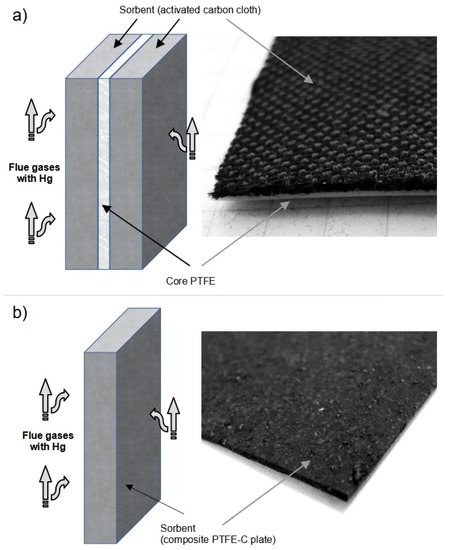
Figure 1.
Two types of materials: FSM—layered sandwich (a), SPC—composite (PTFE-C) plate (b).
Sorbent polymer composite (SPC) is a PTFE-C plate (Figure 1b) made in the process of extrusion and two-direction rolling from a mixture of polytetrafluoroethylene fine powder resin (Tarflen™ PTFE 650XT X) and activated carbon powder (ACTIVUS C with 1% KI) in the proportions of 70% and 30% by weight, respectively.
The role of the individual components of FSM is as follows:
Support layer—should be made of possibly thin and stiff foil that holds the adsorbing material and be resistant to the aggressive atmosphere of flue gases (acids, dust, high humidity, temperature up to 120–200 °C, etc.). Moreover, it should be possible to cover/combine it with the active material—the sorbent.
Sorbent—material with a maximum developed specific surface (above 100 m2/g) and high (approx. 70%) content of micro- (<2 nm) and mesopores (2–50 nm), adapted to the size of Hg-rich particles [29]. The proposed adsorption mechanism for Hgo under the simulated flue gas over the 1% KI activated carbon is well described by L. Tong [30]. The sorbent should be as resistant to the aggressive atmosphere of flue gases as possible. It should be possible to clean/rinse its surface of macro dust. Moreover, it should be possible to combine it with other FSMs without significant changes in porosity and specific surface area.
2.2. Produced Apparatus
Three unique systems were designed and produced in order to test the FSM and SPC materials, designed to remove mercury from the flue gas:
- -
- a system for laboratory tests of materials in the flue gas,
- -
- a mobile system for preliminary industrial tests,
- -
- a larger scale system for final industrial tests.
2.2.1. The Laboratory Stand for Testing FSM and SPC in Flue Gas
Prior to the commencement of industrial tests, the materials should be tested in the flue gas under laboratory conditions. The laboratory system for testing FSM and SPC materials in flue gas is shown in Figure 2. The system is partially based on the powder-sorbent testing stands [21,31].
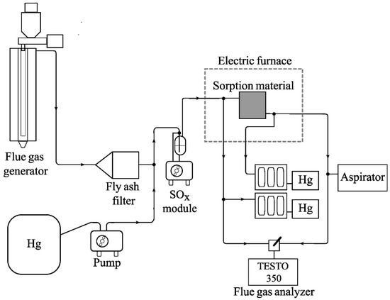
Figure 2.
The laboratory system for testing FSM in flue gas.
The flue gases supplied to the system from the laboratory flue gas generator (AGH UST construction) are cleaned of fly ash in a fly ash filter. In some experiments, nitrogen with mercury vapor was used instead of a flue gas generator. In order to regulate the concentration of mercury in the flue gas, mercury vapors were pumped with a precise peristaltic pump, from the Tedlar bag (concentration of Hg in the bag approx. 4000 g/m3N) to the tee connector, located behind the bag filter. A desulfurization module (laboratory WFGD unit), when used, cleaned the flue gases of SO2 down to a maximum of 300 mg/m3N. The module scrubber contained a CaCO3 suspension. The peristaltic pump module circulated the CaCO3 solution, which absorbed the sulfur oxides. The cleaned flue gas was directed to the PTFE “V1” module containing tested materials. The PTFE V1 module is shown in Figure 3. The PTFE V1 module consisted of two 30 mm thick PTFE plates with milled square holes (35 × 35 mm) 7 mm deep. The tested material was placed between the plates and the flue gas was led through channels of 6 mm and 3 mm diameters. The tightness of the module was ensured by 1 mm silicone gaskets, the number and thickness of which were adjusted depending on the thickness of the tested material. Tarflen plates were connected to each other with a steel clamp with two M6 bolts. In the first version of the module, PTFE plates were joined with four M6 bolts connecting the Tarflen plates directly to each other, but at higher temperatures, during flue gas tests (180 °C), the PTFE plates bent and the modules lost their tightness.
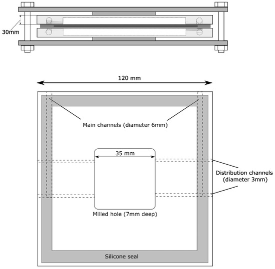
Figure 3.
The Tarflen PTFE V1 module.
The test or flue gases were supplied to the surface of the tested material by Teflon tubes of 6 mm in diameter. One piece of the tested material or three pieces could be placed in the module, one placed between the PTFE plates and two more placed in milled recesses. The PTFE module was placed in a thermostatic chamber (electric furnace). The tee connector in front of the PTFE V1 module enables continuous control of the level of mercury in the flue gas entering the PTFE V1 module (reference line). The mercury concentration in the flue gas was measured with the EMP-2 (NIC) mercury analyzers. The mercury analyzers (post-FSM/SPC and reference one) draw 0.4 dm3 of gas per minute each and a Testo 350 flue gas analyzer—when working—draws 1.0 dm3 of flue gas per minute. The EMP-2 analyzers and Testo 350 work interchangeably. In order to regulate the constant flue gas flow rate through the PTFE V1 module, an aspirator was added to the system. The analyzers equipped with the aspirator made it possible to achieve a 1.5 dm3/min flow inside the PTFE V1 module.
2.2.2. The Industrial System for Preliminary Testing of FSM and SPC Materials
The advantage of the laboratory system is the ability to test materials in the flue gases in comfortable laboratory conditions. On the other hand, the advantage of the industrial system is the ability to test materials in the target flue gas in which the material will be used. Flue gas properties vary widely from plant to plant and therefore the possibility of carrying out fast, low-cost pre-tests of FSM and SPC materials in a specific plant is extremely valuable.
A schematic diagram of an industrial system for testing FSM is shown in Figure 4.
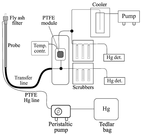
Figure 4.
The industrial stand for preliminary testing of FSM.
The system consisted of a fly ash filter, a probe connected to the transfer line, a mobile heating chamber containing a PTFE V1 module, two scrubber systems (Nippon Instrument Corporation), two EMP-2 detectors (NIC), a 100 dm3 Tedlar bag containing air with mercury vapors at a concentration of about 4000 µg/m3N, a precise peristaltic pump, feeding the gas with mercury vapor to the probe inlet through a Teflon tube, a cooler with flue gas treatment system, pump, and temperature control system.
The system made it possible to carry out research on the effectiveness of mercury removal by the FSM-based module, from industrial, coal origin flue gas. In the case of low Hg concentration values in the flue gas, during the tests, it was possible to increase the Hg concentration by introducing mercury vapors into the system using a peristaltic pump. The use of an additional pump made it possible to adjust the flue gas stream flowing through the PTFE V1 module in the range from 0.4 to 9.5 dm3/min. The mobile heating chamber made it possible to regulate the temperature of the test module. One of the EMP-2 detectors measured the concentration of total mercury in the flue gas after passing through the module with the FSM, while the other was used in the reference flue gas, unmodified by the FSM.
2.2.3. The Larger Scale Industrial System for Testing Composite Materials
Experience with the use of a preliminary version of the industrial test system enabled the construction of a large version of the system. After preliminary industrial tests, the final version of the measurement system was designed for industrial testing (Figure 5). The developed prototype modules (3 pieces of each of FSM and SPC sorption materials) were tested in real conditions in a coal-fired (lignite) power plant block with a total power of over 450 MWt.
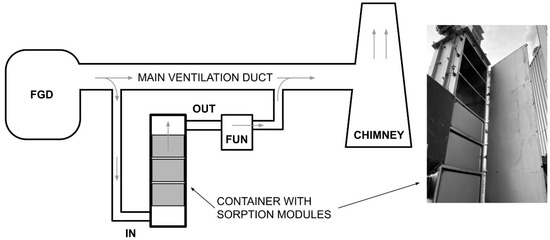
Figure 5.
The scheme of the industry Hg capture testing system.
Fixed sorbent materials: FSM—the layered sandwich—and SPC—composite (PTFE-C) plate—were used to build sorption modules (Figure 6) capturing mercury during industrial tests.
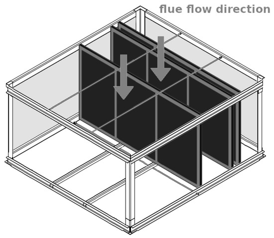
Figure 6.
The prototype of the sorption module “V2” for industrial tests.
Three sorption modules were made of each type of fixed sorbent material. The active area of a single module made of FSM was 21.6 m2 and that of SPC was 22.7 m2. The sorption modules (made of the same material) were installed in the container on the bypass of the ventilation duct between the flue gas desulfurization (FGD) installation and the chimney.
The flue gas flow rate was regulated by an additional draft fan. The TEKRAN 3300 analyzer was used to measure the mercury concentrations (Hg(0) and Hg(II) forms) in the flue gas.
2.3. Procedures
The following are the FSM and SPC testing procedures, developed when testing the constructed apparatus.
2.3.1. The Procedure of Laboratory Tests in an Inert Gas
- A sample of the test FSM was cleaned by blowing off loose AC dust with a jet of air from a compressor (3 bar). The PTFE V1 module was cleaned with 10% nitric acid forced into the module by a peristaltic pump (10 min of cleaning) and distilled water and air blown from an oil-free compressor.
- An FSM sample of 6 × 6 cm was inserted between the elements of the PTFE V1 module. The module was sealed (silicone gaskets) and compressed with a steel clamp. Then, the elements of the test system were connected using 6 mm Teflon tubes.
- A Tedlar® bag with a test gas was connected behind the fly ash filter (Figure 2).
- System sorption control. The tests were performed for all gas streams: 0.4; 1.5; 3.5; 5.5; 7.5; and 9.5 dm3/min.
- Tests of mercury sorption on FSM (successively for temperatures 25 °C, 60 °C, 120 °C). The PTFE V1 module was heated to the appropriate temperature (measurement of gas temperature inside the module chamber). Then, mercury sorption measurements were performed, successively at the flow rates of 0.4, 1.5, 3.5, 5.5, 7.5, and 9.5 dm3/min.
- Cleaning the measuring system. After disassembling the module and removing sorption materials, the channels of both module elements were blown with air from an oil-free compressor (pressure 8 bar), then the elements were rinsed with distilled water, washed with 10% nitric acid, and rinsed again with deionized water. After drying, the Teflon module was assembled and the mercury sorption was monitored. In the case of Hg sorption greater than 10–15%, the washing procedure was repeated.
2.3.2. The Procedure of Laboratory Tests in Flue Gas
- A sample of the tested FSM was cleaned by blowing off loose AC dust with a jet of air from a compressor (3 bar). The PTFE V1 module was cleaned with 10% nitric acid forced into the module by a peristaltic pump (10 min of cleaning) and distilled water and air blown from an oil-free compressor.
- A sample of 6 × 6 cm was inserted between the elements of the PTFE V1 module. The module was sealed (silicone gaskets) and compressed with a steel clamp.
- Heating the module to a temperature 30 degrees higher than the operating temperature.
- Stabilization of the background mercury concentration level (max. background 1.5 µg/m3N).
- Lowering the furnace chamber temperature to the operating temperature.
- Starting the mercury and flue gas sources. Determination of mercury concentration at the level of 20–40 µg/m3N.
- Optional activation of the flue gas desulfurization laboratory unit.
- Measurement of mercury sorption with the flue gas flow of 1.5 dm3/min. Every 20 min, control of SO2 concentration and possible adjustment of desulfurization system—SO2 concentration at the level of about 100 mg/m3N.
- Turning off the flue gas generator and turning off the mercury source.
- Turning off the system and visual inspection of the cell and composite material after cooling.
- System cleaning. After disassembling the module and removing the fixed sorbent material, the channels of both module elements were blown with air from an oil-free compressor (pressure 8 bar). Then, the elements were rinsed with distilled water, washed with 10% nitric acid, and rinsed again with deionized water. After drying, the Tarflen module was assembled and the mercury sorption was monitored. If the Hg sorption of the empty module was greater than 10–15%, the washing procedure was repeated.
2.3.3. The Procedure of Final Industrial Tests
- A container with three sorbent modules made of the same type of sorbent material (FSM or SPC) was mounted in the bypass of the ventilation duct (Figure 6).
- With the use of an additional draft fan, the flue gas flow rate in the bypass was set to 120 m3/min.
- Before starting the actual tests, the modules were conditioned in a working industrial installation for 14 days.
- After the conditioning period, the following parameters were measured every 3 min: mercury concentration (with speciation) in the flue gas before and behind the container with modules (inlet/outlet), oxygen concentration in the flue gas, external temperature, temperature before and behind the container with the tested modules and behind the fan, flue gas flow rate and pressure before and behind the container.
- The container test with FSM modules lasted over 42 days, while the test of the container with SPC modules lasted 34 days.
3. Results and Discussion
3.1. Basic Tests of FSM and SPC Materials Used for Testing Stands
Activated carbon in the forms of an ACC fibrous cloth (FSM) and a powder in the PTFE-C composite plate (SPC) was selected as the sorbent material. The microstructure (SEM) and elemental composition analysis (EDS) of these materials are shown in Figure 7 and Figure 8. The results of the measurements of the specific surface area and the total volume and size of pores of these materials determined by the BET method are presented in Figure 9 and Table 1.

Figure 7.
Microstructure SEM—magnification 8000× (A) and 150× (B) of ACC cloth (part of FSM) and elemental analysis (EDS) of carbon distribution (C).

Figure 8.
Microstructure SEM—magnification 130× of PTFE-C composite plate SPC (A) and elemental analysis (EDS) of carbon (B) and fluor (C) distributions.
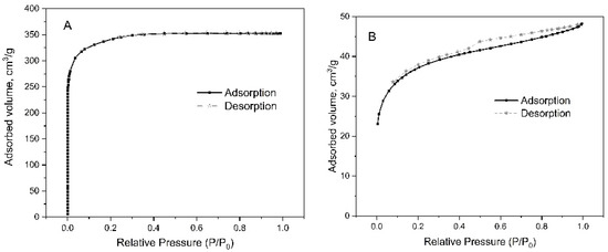
Figure 9.
BET adsorption–desorption isotherms for FSM (A) and SPC (B) fixed sorbent materials.

Table 1.
The specific surface area and the total volume and size of pores determined by the BET method of fixed sorbent materials (FSM (ACC) and SPC).
Generally, it can be stated that fixed sorbent material (FSM) has about 10 times greater specific surface area (BET) and total pore volume than SPC. The average pore size of both these materials is similar and amounts to about 2 nm.
3.2. Tests of the Laboratory System
3.2.1. Analytical Problems Related to the FSM Used during the Tests of the Systems
The problem that arose at the beginning of testing was that fixed sorbent materials released powdery activated carbon during the measurement. Active carbon, deposited on the walls of the chamber and other elements of the system, caused errors in the assessment of the effectiveness of mercury sorption by the tested material. Here are the results of an experiment, the purpose of which was to determine the level of mercury sorption by the system itself and to develop a method of cleaning the system after the test of FSM. In this experiment, the mercury concentration in the test gas was 28.8 µg/m3N. The hole system with FSM at 25 °C removed about 98% of mercury from the test gas, after removing the material, the system removed 42% of mercury, after purging and washing with water, mercury sorption dropped to 23%. Using 10% nitric acid for 20 min made it possible to reduce mercury sorption by the system to the level of 5–10%. Therefore, during the measurements, it was necessary to measure system sorption each time and to take into account the individual sorption level at each measurement. The SPC material did not cause the problems described above, due to the fact that there was no AC dusting.
3.2.2. The Effect of the Shape of the PTFE V1 Module and Material Area on the Effectiveness of Mercury Removal
The purpose of the Tarflen module V1 tests was to support the process of developing the final industrial version of the module. The PTFE V1 module had the ability to change the chamber volume in the range from 3.5 to 24.5 cm3. The volume change was carried out by means of replaceable PTFE inserts of varying thickness. The two inserts were placed in milled holes in the chamber. Two types of Tarflen inserts with a thickness of 3.5 and 6 mm were used for the tests. Due to the use of inserts, the distance between the surface of the sorbent material and the walls of the chamber in the following experiments was the following: 1 mm (6 mm insert); 3.5 mm (3.5 mm insert); and 7 mm (no insert). In this experiment, nitrogen with the addition of mercury vapor was used instead of a flue gas generator. The mercury concentration in the test gas in this experiment was 38.2 µg/m3 and the FSM was used in this test. The linear velocity of the test gas along the surface of the material was constant and in all three tests and amounted to approx. 0.24 m/s. In order to maintain a constant linear velocity of the test gas along the tested material, due to the changing volume of the chamber, it was necessary to change the size of the gas stream. The change of the gas stream size in the PTFE V1 module chamber was realized by changing the efficiency of the additional pump.
The relationship between the % of mercury removed and the distance of the tested material from the chamber wall was linear R2 = 0.9947. According to the research, changing the distance between the material and the wall of the chamber from 7 to 1 mm twice increases the effectiveness of mercury removal by the FSM. In order to determine the effect of the increase in the surface area of the composite material on the effectiveness of mercury removal from the test gas, an experiment was carried out in which, instead of 3.5 mm thick Tarflen inserts, two additional pieces of FSM with dimensions of 3.5 × 3.5 cm were used. The above-mentioned alteration changed the mercury sorbent surface in the gas from 24.5 cm2 to 49 cm2 (200%). Due to the thickness of the sorbent material, the distance between the sorbent surfaces was 3.5 mm. As a result of increasing the surface area of the FSM, Hg sorption increased from 66.5 ± 0.5% to 91.9 ± 1.6%. As can be seen, the doubling of the surface area of the mercury absorbing material resulted in an increase in sorption of Hg by 38.2%.
3.2.3. The Effect of Test Gas Velocity on Mercury Removal Efficiency
In FSM testing, the effect of gas velocity (along the surface of the material) on the mercury removal efficiency is an important issue. In this experiment, nitrogen with the addition of mercury vapor was used instead of a flue gas generator. Below (Table 2 and Table 3) are the results of an experiment with FSM and SPC materials in test gas that differ in mercury removal efficiency. Both materials were tested at 25 °C.

Table 2.
The effect of gas velocity on mercury removal efficiency (FSM).

Table 3.
The effect of gas velocity on mercury removal efficiency (SPC material).
With both types of materials, an increase in the gas velocity along the surface of the material causes a decrease in the amount of mercury absorbed. At the same time, it can be seen that the tested FSM was definitely more effective (about 60–90% of Hg removal) than SPC material (about 2–16% of Hg removal).
3.2.4. The Influence of Temperature on Mercury Removal Efficiency
The laboratory setup allows materials to be tested at different temperatures. Table 4 shows the test results for the FSM at three different temperatures of 25 °C, 60 °C, and 120 °C. In this experiment, nitrogen with the addition of mercury vapor was used instead of a flue gas generator.

Table 4.
FSM testing at three different temperatures of 25 °C, 60 °C, and 120 °C.
As can be seen from Table 4, the mercury removal efficiency of FSM increases (from about 92 to 97%) with increasing temperature. This effect may be related to the action of iodine, which was a component of sorption material part of the FSM.
3.2.5. PTFE Membrane Permeability Tests
In order to obtain reliable test results for various materials, it is necessary to determine whether the membranes or the construction materials of FSM are gas permeable. In the case of a pressure difference on both sides of the material, a test gas or flue gases may pass through the material, which may increase the % of mercury removed by the material. The specific structure of the materials used for the tests made it necessary to conduct an additional test to determine the permeability of the membranes, which are the construction part of the FSM. During tests with the module V1, gas or flue gases containing mercury flow from both sides of the tested material. In the case of pressure differences in the channels and the gas permeability of the material being tested, the mercury can pass from one channel to the other, increasing the amount of adsorbed mercury, making it difficult to compare gas-permeable and gas-impermeable materials. The tests were carried out using the PTFE V1 module. Three membranes were tested in the research—a Tedlar membrane that was mercury impermeable and two membranes used as a construction part of the fixed sorbent materials: “43” and “10”.
A test gas containing mercury flowed through the “CH1” channel. Air flowed through the “CH2” channel. The flow of gas streams in the CH1 and CH2 channels was forced by two EMP-2 detector pumps. A membrane was placed between the channels in the PTFE V1 module. The pressure in the channels was changed during the experiment. As a result of the pressure difference between the channels, mercury was transferred (or not) from the CH1 channel (Hg) to CH2 channel (air).
Figure 10 is a graphic illustration of the mercury permeability of the tested membranes.
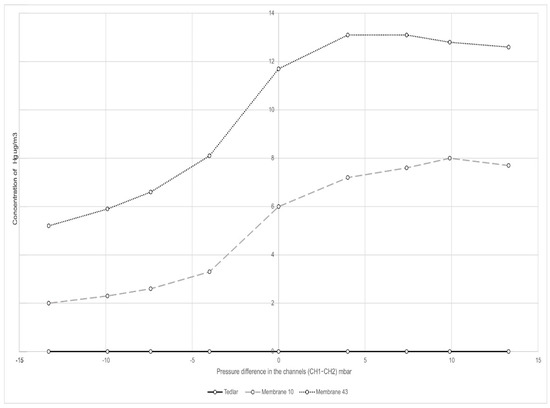
Figure 10.
Dependence of mercury concentration in the CH2 channel on the pressure difference between the channels.
Tedlar is mercury impermeable. In this case, mercury does not pass from the CH1 channel to CH2 channel and the mercury concentration in the CH2 channel is zero throughout the experiment. In the case of “43” and “10” membranes, reducing the pressure in the CH2 channel causes the mercury to pass from the CH1 (Hg) channel to the CH2 (air) channel. The more permeable the membrane, the more mercury passes from the CH1 channel to CH2 channel. As can be seen from the diagram, diaphragm “43” is more permeable to mercury than diaphragm “10”.
3.2.6. Laboratory Tests of FSM in Flue Gas
The tests of the laboratory system equipped with the flue gas generator were carried out with the use of FSM. The purpose of this test was to check the laboratory system and to learn about the behavior of the tested material in the flue gas before industrial tests. The tests of the laboratory system equipped with the flue gas generator were carried out with the use of FSM. The material was tested at a temperature of 120 °C. The flue gas flow rate through the PTFE V1 module was 1.5 dm3/min and the measurement time was 70 min.
The average λ and flue gas composition during this experiment, supplied by the mobile flue gas laboratory generator, are shown in Table 5.

Table 5.
Flue gas composition during FSM tests in flue gas.
The mercury concentration in the flue gas was 75.4 ± 4.6 µg/m3. During the experiment, the FSM removed about 91% of mercury from the flue gases during the first period of the experiment and about 84% at the end of the experiment (before 70 min). It is a value close to the value obtained in the laboratory gas tests (nitrogen + mercury), with the same flow rate through the module, when the same fixed sorbent material module removed about 96% of mercury. The longer duration of the experiment showed that the effectiveness of mercury removal in the flue gas by FSM may decrease over time.
3.3. Results of Tests of Mobile Industrial System
The purpose of creating a small industrial system was to determine the effectiveness of mercury removal by the FSM in the flue gas at different flue gas velocities, temperatures, and different concentrations of mercury and to obtain the information necessary to construct a large industrial module.
Industrial tests were carried out at a power plant in the Czech Republic equipped with a fluidized bed boiler firing a mixture of 45% lignite, 45% hard coal, and 10% biomass. The composition of flue gases during the experiment was as follows: O2—4.5%; CO2—12%; NOx—87 mg/m3N; CO—94 mg/m3N; SO2—143 mg/m3N. The linear velocity of the flue gases in the PTFE V1 module, during the experiment, was 0.4 m/s. The system described in Section 2.2.2 was used for the experiment. Due to the small amount of mercury in the original flue gas, mercury was added to the flue gas using a precision peristaltic pump.
In order to test the mobile industrial system and determine the effect of mercury concentration on the effectiveness of its removal by FSM, the Hg concentration was increased during the experiment from about 31 to about 117 µg/m3. The results of the experiment are presented in Table 6.

Table 6.
Influence of Hg concentration on mercury removal by FSM.
As shown in Table 6, in the case of FSM, the change in Hg0 concentration in the range from approx. 31 to approx. 117 µg/m3N does not affect the effectiveness of mercury removal from the flue gas. At the same time, it was found that it is possible to smoothly regulate the mercury concentration in the flue gas in order to simulate a mercury concentration other than the one found in the power plant.
Another industrial experiment confirmed the possibility of testing materials at different temperatures and at different flue gas velocities.
Table 7 and Table 8 show the results of the determination of mercury in the flue gas after it has passed through the PTFE V1 module with FSM, which was kept successively at the temperatures of 60 °C and 120 °C.

Table 7.
The results of the determination of Hg in the flue gas after passing through the module (60 °C).

Table 8.
The results of the determination of Hg in the flue gas after passing through the module (120 °C).
As can be seen from Table 7 and Table 8, the dependence of the mercury removal efficiency on the speed and temperature of the flue gas in the case of the industrial test is quite analogous to that in the case of tests in inert gas with Hg. However, we can observe a lower efficiency of the material (80.7%) in relation to measurements in laboratory gas (95.0%), which results from the rich matrix of flue gases.
The tests described again allowed for the construction of a large V2 module, which was used in industrial conditions for testing materials.
3.4. Final Industrial System Tests
The V2 modules made with use of FSM were tested for over 42 days (61,515 min) between November and December. During the entire testing period, the value of parameters, such as: oxygen concentration (5 ± 1%), temperature before (66 ± 2 °C) and behind (63 ± 3 °C) the container, flow rate (120 ± 5 m3/min), and pressure difference (0.80 ± 0.05 kPa) before and behind container, remained at a stable and constant level.
The results of the continuous measurement of mercury concentration in the flue gas inlet/outlet are presented in Figure 11.
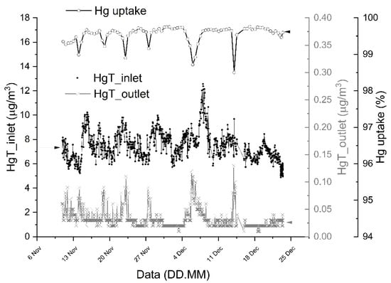
Figure 11.
The content and capture of mercury in the flue gas at the inlet and outlet of a container with modules made of FSM during 42 days of industrial test.
The average total (HgTotal = elemental + ionic) mercury content in the flue gas, before the container with tested modules, during the 42 days of measurement, was 8.7 µg/m3, while behind the container, the average mercury HgTotal content was 0.03 µg/m3. The amount of gaseous total mercury measured in the flue gas consists of its forms (speciation): elemental mercury (Hg0) and ionic bivalent mercury (Hg2+). Ion mercury (average value—0.25 µg/m3) constitutes 2.7% of the total mercury content in the exhaust gas (after FGD), which is consistent with the literature data [32]. The level of Hg uptake (approx. 99.5%) did not significantly change after 42 days of industrial tests (no change in the Hg uptake efficiency was observed—there was no effect of sorbent saturation). The three tested modules with a total active area of 648,000 cm2 during the 60,690 min test captured 53.1 g of mercury. That is, on average, 1 cm2 of FSM sorbed 0.082 mg of mercury at the rate of 0.00135 µg/min.
Tests of modules made of SPC sorbent material were carried out for 34 days (48,960 min) in the period from January–February. During the entire testing period, the value of parameters, such as: oxygen concentration (5 ± 1%), temperature before (66 ± 2 °C) and behind (63 ± 3 °C) the container, flow rate (120 ± 5 m3/min), and pressure difference (0.80 ± 0.05 kPa) before and behind container, remained at a stable and constant level.
The concentration of mercury in the flue gas at the inlet to the container with modules made of SPC material was 8 μg/m3N (test start) and 17 μg/m3N (the end of test—after 34 days), while at the outlet it was 0.05 μg/m3N (start) and 3 μg/m3N (end), respectively. That is, after 34 days of testing, the capture efficiency decreased from 99.4% to 82.3% which may indicate a partial saturation of the SPC material. The three tested modules with a total active area of approx. 680,000 cm2 during 48,960 min captured at least 29.2 g of mercury. That is, on average, 1 cm2 of SPC material sorbed 0.043 mg of mercury at the rate of 0.00088 µg/min.
As expected, the FSM, which has a specific surface area 10 times greater than the SPC material, showed a much greater ability to capture Hg from flue gas in industrial tests. However, it should be emphasized that both types of modules (made of FSM and SPC materials) installed in the power plant’s flue gas channel (bypass) reduced the Hg emission to the level of 1–7 μg/m3N recommended in the BAT conclusions [33].
4. Summary
Three stands (systems) and procedures determining mercury capture by FSM and SPC have been developed. The systems had to be preliminarily examined. Numerous tests with use of the chosen FSM and SPC revealed the usefulness of the methods, and proper operation of stands, both in the laboratory and industrial conditions. The influences of FSM or SPC module shapes (the internal layout and contact surface of active materials), flue gas properties (e.g., composition, temperature, flow rate), and mercury concentration on the effectiveness of mercury removal by SPC and FSM are possible to be measured by these systems, however, studying the impact of all of these factors is complex and time-consuming. In this paper, we particularly described the influence of module shapes, gas velocity, and temperature on mercury capture by FSM and SPC modules.
Laboratory measurements are primarily performed to compare the effectiveness of a larger number of materials fixed inside one module. Measurements in the industrial module are used to check the performance of the previously selected, best material(s) in long-term tests.
In laboratory tests, FSM removed from about 84 to 91% of mercury from exhaust gases at 120 °C. In the case of tests with laboratory gases (N2 + Hg), the percentage of mercury removed was higher and amounted to approx. 96%. In the final industrial tests, the FSM removed 99.5% of mercury after 42 days and the SPC material removed from 99.5% to 82.3% after 34 days.
Author Contributions
Conceptualization, J.G. and M.M.; methodology, J.G., M.M., M.W. and Y.D.; validation, J.G.; formal analysis, J.G. and Y.D.; investigation, J.G., M.M., J.C., K.B., M.W., Y.D. and G.P.; resources, K.B. and G.P.; data curation, J.C.; writing—original draft preparation, J.G., M.M., Y.D. and G.P.; writing—review and editing, J.G.; visualization, J.G. and J.C.; supervision, K.B. and G.P.; project administration, J.G., M.M. and J.S.; funding acquisition, K.B. and J.S. All authors have read and agreed to the published version of the manuscript.
Funding
The work was supported by: the National Centre for Research and Development within framework of the Project “Composite adsorber for limiting mercury emissions in flue gases” (POIR.01.01.01-00-1119/17-0) co-financed by the European Regional Development Fund (Intelligent Development Operational Program 2014-2020), AGH University of Science and Technology grant no. 16.16.210.476.
Institutional Review Board Statement
Not applicable.
Informed Consent Statement
Not applicable.
Data Availability Statement
Not applicable.
Conflicts of Interest
All authors declare that there is no conflict of interest.
References
- Kalisinska, E.; Gorecki, J.; Okonska, A.; Pilarczyk, B.; Tomza-Marciniak, A.; Budis, H.; Lanocha, N.; Kosik-Bogacka, D.I.; Kavetska, K.M.; Macherzynski, M.; et al. Hepatic and Nephric Mercury and Selenium Concentrations in Common Mergansers, Mergus Merganser, from Baltic Region, Europe. Environ. Toxicol. Chem. 2014, 33, 421–430. [Google Scholar] [CrossRef] [PubMed]
- United Nations Environmental Programme. Global Mercury Assessment 2018: Sources, Emissions, Releases and Environmental Transport; UN Environment Programme: Geneva, Switzerland, 2018; pp. 1–60. [Google Scholar]
- Kamata, H.; Ueno, S.; Naito, T.; Yukimura, A. Mercury Oxidation over the V2O5(WO3)/TiO2 Commercial SCR Catalys. Ind. Eng. Chem. Res. 2008, 5, 8136–8141. [Google Scholar] [CrossRef]
- Yang, W.; Adewuyi, Y.G.; Hussain, A.; Liu, Y. Recent developments on gas–solid heterogeneous oxidation removal of Elemental mercury from flue gas. Environ. Chem. Lett. 2019, 17, 19–47. [Google Scholar] [CrossRef]
- Niu, Q.; Luo, J.; Sun, S.; Chen, Q.; Lu, J. Effects of Flue Gas Components on the Oxidation of Gaseous Hg0 by Dielectric Barrier Discharge Plasma. Fuel 2015, 150, 619–624. [Google Scholar] [CrossRef]
- Chang, L.; Zhao, Y.; Li, H.; Tian, C.; Zhang, Y.; Yu, X.; Zhang, J. Effect of sulfite on divalent mercury reduction and re-emission in a simulated desulfurization aqueous solution. Fuel Process. Technol. 2017, 165, 138–144. [Google Scholar] [CrossRef]
- Zhang, Y.; Yang, J.; Yu, X.; Sun, P.; Zhao, Y.; Zhang, J.; Chen, G.; Yao, H.; Zheng, C. Migration and emission characteristics of Hg in coal-fired power plant of China with ultra low emission air pollution control devices. Fuel Process. Technol. 2017, 158, 272–280. [Google Scholar] [CrossRef]
- Górecki, J.; Łoś, A.; Macherzyński, M.; Gołaś, J.; Burmistrz, P.; Borovec, K. A portable, continuous system for mercury speciation in flue gas and process gases. Fuel Process. Technol. 2016, 154, 44–51. [Google Scholar] [CrossRef]
- Pilar, L.; Borovec, K.; Szeliga, Z.; Górecki, J. Mercury emission from three lignite-fired power plants in the Czech Republic. Fuel Process. Technol. 2021, 212, 106628. [Google Scholar] [CrossRef]
- Górecki, J.; Burmistrz, P.; Trzaskowska, M.; Sołtys, B.; Gołaś, J. Method development and validation for total mercury determination in coke oven gas combining a trap sampling method with CVAAS detection. Talanta 2018, 188, 293–298. [Google Scholar] [CrossRef]
- Zhou, Q.; Tao, X.; Di, G.; Shang, Y.; Lu, P.; Xu, G.; Liu, M.; Zheng, Y.; Dong, L. Elemental mercury capture from flue gas by magnetic recyclable Fe6Mn1-XCexOy sorbent. Part 1. Performance evaluation and regeneration. Fuel 2021, 304, 120723. [Google Scholar] [CrossRef]
- Wu, S.; Yan, P.; Yu, W.; Cheng, K.; Wang, H.; Yang, W.; Zhou, J.; Xi, J.; Qiu, J.; Zhu, S.; et al. Efficient removal of mercury from flue gases by regenerable cerium-doped functional activated carbon derived from resin made by in situ ion exchange method. Fuel Process. Technol. 2019, 196, 106167. [Google Scholar] [CrossRef]
- Xu, Y.; Zhou, M.; Chen, M.; Zhang, Q.; Du, L.; Luo, G. Simultaneous removal of NO and elemental mercury from coal-fired flue gas using natural ferruginous manganese ore at low temperature. Fuel 2022, 326, 125118. [Google Scholar] [CrossRef]
- Coker, A.K. Industrial and Laboratory Reactors—Chemical Reaction Hazards and Process Integration of Reactors; John Wiley and Sons: Hoboken, NJ, USA, 2015; ISBN 9780750685245. [Google Scholar]
- Zhou, Q.; Duan, Y.-F.; Zhao, S.-L.; Zhu, C.; She, M.; Zhang, J.; Wang, S.-Q. Modeling and experimental studies of in-duct mercury capture by activated carbon injection in an entrained flow reactor. Fuel Process. Technol. 2015, 140, 304–311. [Google Scholar] [CrossRef]
- Kogut, K.; Górecki, J.; Burmistrz, P. Opportunities for reducing mercury emissions in the cement industry. J. Clean. Prod. 2021, 293, 126053. [Google Scholar] [CrossRef]
- Czarna, D.; Baran, P.; Kunecki, P.; Panek, R.; Żmuda, R.; Wdowin, M. Synthetic zeolites as potential sorbents of mercury from wastewater occurring during wet FGD processes of flue gas. J. Clean. Prod. 2018, 172, 2636–2645. [Google Scholar] [CrossRef]
- Wiatros-Motyka, M.M.; Sun, C.; Stevens, L.A.; Snape, C.E. High capacity co-precipitated manganese oxides sorbents for oxidative mercury capture. Fuel 2013, 109, 559–562. [Google Scholar] [CrossRef]
- Marczak-Grzesik, M.; Budzyń, S.; Tora, B.; Szufa, S.; Kogut, K.; Burmistrz, P. Low-cost organic adsorbents for elemental mercury removal from lignite flue Gas. Energies 2021, 14, 2174. [Google Scholar] [CrossRef]
- Xu, W.; Adewuyi, Y.G.; Liu, Y.; Wang, Y. Removal of Elemental Mercury from Flue Gas Using CuOx and CeO2 Modified Rice Straw Chars Enhanced by Ultrasound. Fuel Process. Technol. 2018, 170, 21–31. [Google Scholar] [CrossRef]
- Wdowin, M.; Macherzyński, M.; Panek, R.; Górecki, J.; Franus, W. Investigation of the sorption of mercury vapour from exhaust gas by an Ag-X zeolite. Clay Miner. 2015, 50, 31–40. [Google Scholar] [CrossRef]
- Tauanov, Z.; Tsakiridis, P.E.; Mikhalovsky, S.V.; Inglezakis, V.J. Synthetic coal fly ash-derived zeolites doped with silver nanoparticles for mercury(II) removal from water. J. Environ. Manag. 2018, 224, 164–171. [Google Scholar] [CrossRef]
- Pasinszki, T.; Krebsz, M.; Chand, D.; Kótai, L.; Homonnay, Z.; Sajó, I.E.; Váczi, T. Carbon microspheres decorated with iron sulfide nanoparticles for mercury(II) removal from water. J. Mater. Sci. 2020, 55, 1425–1435. [Google Scholar] [CrossRef]
- Budihardjo, M.A.; Wibowo, Y.G.; Ramadan, B.S.; Serunting, M.A.; Yohana, E. Syafrudin mercury removal using modified activated carbon of peat soil and coal in simulated landfill leachate. Environ. Technol. Innov. 2021, 24, 102022. [Google Scholar] [CrossRef]
- Wejkowski, R.; Kalisz, S.; Tymoszuk, M.; Ciukaj, S.; Maj, I. Full-scale investigation of dry sorbent injection for NOx emission control and mercury retention. Energies 2021, 14, 7787. [Google Scholar] [CrossRef]
- Cheng, Y.; Asaoka, Y.; Hachiya, Y.; Moriuchi, N.; Shiota, K.; Oshita, K.; Takaoka, M. Mercury emission profile for the torrefaction of sewage sludge at a full-scale plant and application of polymer sorbent. J. Hazard. Mater. 2022, 423, 127186. [Google Scholar] [CrossRef] [PubMed]
- Bucatariu, F.; Teodosiu, C.; Morosanu, I.; Fighir, D.; Ciobanu, R.; Petrila, L.M.; Mihai, M. An overview on composite sorbents based on polyelectrolytes used in advanced wastewater treatment. Polymers 2021, 13, 3963. [Google Scholar] [CrossRef] [PubMed]
- Knotts, J.; Guenioui, K. A Complete Mercury Control System. Available online: https://www.gore.com/sites/default/files/2017-07/IEEE-article-July-2017.pdf (accessed on 17 November 2022).
- Peng, Y.; Shi, N.; Wang, J.; Wang, T.; Pan, W.-P. Mercury speciation and size-specific distribution in filterable and condensable particulate matter from coal combustion. Sci. Total Environ. 2021, 787, 147597. [Google Scholar] [CrossRef]
- Tong, L.; Yue, T.; Zuo, P.; Zhang, X.; Wang, C.; Gao, J.; Wang, K. Effect of characteristics of KI-impregnated activated carbon and flue gas components on Hg0 removal. Fuel 2017, 197, 1–7. [Google Scholar] [CrossRef]
- Wdowin, M.; Macherzyński, M.; Panek, R.; Wałęka, M.; Górecki, J. Analysis of selected mineral and waste sorbents for the capture of elemental mercury from exhaust gases. Mineralogia 2020, 51, 17–35. [Google Scholar] [CrossRef]
- Stergaršek, A.; Horvat, M.; Kotnik, J.; Tratnik, J.; Frkal, P.; Kocman, D.; Jaćimović, R.; Fajon, V.; Ponikvar, M.; Hrastel, I.; et al. The role of flue gas desulphurisation in mercury speciation and distribution in a lignite burning power plant. Fuel 2008, 87, 3504–3512. [Google Scholar] [CrossRef]
- Commission Implementing Decision (EU) 2021/2326 of 30 November 2021. Available online: https://eur-lex.europa.eu/legal-content/EN/TXT/HTML/?uri=CELEX:32021D2326&from=EN (accessed on 17 November 2022).
Publisher’s Note: MDPI stays neutral with regard to jurisdictional claims in published maps and institutional affiliations. |
© 2022 by the authors. Licensee MDPI, Basel, Switzerland. This article is an open access article distributed under the terms and conditions of the Creative Commons Attribution (CC BY) license (https://creativecommons.org/licenses/by/4.0/).