Article

Fast Fault Detection and Active Isolation of Bidirectional Z-Source Circuit Breaker with Mechanical Switch

1
School of Social Safety System Engineering, Hankyoung National University, 327 Chungang-ro, Anseong-si 17579, Gyeonggi-do, Republic of Korea
2
Reliability Assessment Center, Hyundai Electric & Energy System Co., Ltd., 17-10 Mabuk-ro, 240 bean-gil, Giheung-gu, Yongin-si 16891, Gyeonggi-do, Republic of Korea
3
School of Social Safety System Engineering, Research Center for Safety and Health, Hankyoung National University, 327 Chungang-ro, Anseong-si 17579, Gyeonggi-do, Republic of Korea
4
Department of Electrical Engineering, Bucheon University, 25 Sinheung-ro, 56beon-gil, Bucheon-si 14632, Gyeonggi-do, Republic of Korea
*
Authors to whom correspondence should be addressed.
Energies 2022, 15(23), 8899; https://doi.org/10.3390/en15238899
Submission received: 7 October 2022 / Revised: 10 November 2022 / Accepted: 23 November 2022 / Published: 24 November 2022

Abstract

:
In this paper, a new design is provided so that the Z-source circuit breaker with a mechanical switch operates quickly at a low-impedance fault. When the fault occurs, the Z-source circuit breaker uses an impedance network to generate forced current zero crossing on the switch. This current zero-crossing time is not sufficient when mechanical switches are applied. In addition, since the MS switch operates through the fault detection sensor, the speed is slowed down. At a slower speed, the circuit breaker may not allow fault current isolation. To solve this problem, the Thomson coil was added to the circuit. It operates immediately in a low-impedance fault without additional fault detection devices. As a result, the faster operating speed is expected to reduce the size of the Z-source circuit breaker component and the stress of the breaker. It is mathematically analyzed and derived, and verified through simulations and experiments. The main features of the proposed model are fast detection and operation, normal-state circuit disconnect, fault current limitation, and low conduction loss.

1. Introduction

In recent years, demand for DC systems such as renewable energy, electric vehicles, and HVDC transmission has been increasing. As a result, interest in DC power transmission and DC grid systems has been increasing [1]. The DC grid can supply power without loss of conversion. In addition, there are advantages such as a reduced number of conductors, asynchronous operation, and an increase in efficiency compared to AC [2,3]. However, the DC grid is not activated due to the absence of circuit breakers. Unlike AC, the fault current of the DC system does not generate a current zero crossing. The low-impedance characteristic of the DC rapidly increases the fault current [4,5,6]. It can cause serious damage to power conversion devices used in the DC system. Therefore, the DC circuit breaker must be fast enough not to damage power converters. In some recent papers, it has been stated that if the circuit breaker isolates the fault within 5–10 ms, the power conversion devices do not fail [7]. Considering the size of the system and the importance of power converters, this requires faster isolation speeds. Due to the DC characteristic, it is difficult to design circuit breakers.
Until now, many studies have been conducted on DC circuit breakers. Representative DC circuit breakers can be classified into three types [8,9,10]: mechanical circuit breaker (MCB) [11,12], solid-state circuit breaker (SSCB) [13,14,15], and hybrid circuit breaker (HCB) [16,17,18]. The MCB is made up of only pure mechanical switches (MS) has a large capacity, low power loss, and excellent economic feasibility. However, the MS is slow, and an arc is generated at the contact during fault isolation. If there is no current zero crossing, the arc may persist. Even if there is a current zero crossing, reignition may occur if the contact is not sufficiently widened [19]. Due to this problem, the MCB should consider the opening speed of the contact, current zero-crossing timing, and fast isolation speed. For the SSCB, a semiconductor switch is used. It has no arcs and is capable of rapid fault isolation. However, the IGBT used as a switch has a large power loss and low capacity under normal conditions. Semiconductor switches require many serial, parallel connections and protective devices to withstand overcurrent. Such a stacking method has a large capacity, is very expensive, and is difficult to construct an actual system. The HCB uses both mechanical and semiconductor switches. It has a fast speed and low power loss. However, the control between the mechanical and the semiconductor switches is complicated and expensive.
Z-source circuit breaker (ZCB) was first proposed in 2012 [20]. It comes from a Z-source inverter and is a solid state circuit breaker using thyristor (SCR). The Z-source inverter creates voltage boosting using the shoot-through mode that the existing voltage source converter does not allow. The shoot-through mode is similar to the fault [21]. The ZCB creates a forced current zero crossing on the switch through network impedance consisting of capacitors and inductors in a fault. The SCR turns off immediately when the current is zero and quickly isolates the fault. The advantages of the existing ZCB are as follows.
  • Active operation in case of fault;
  • Immediate operation without fault detection sensor;
  • SCR enables fast speed;
  • Easy to control;
  • Suppressing the rise of fault current due to the current limiting capability of the ZCB.
Researchers have noted that the ZCB causes the detection and isolation of the fault simultaneously. Thus, several models have been proposed so far to improve and develop the performance of the ZCB [22,23,24,25]. Reference [22] proposes a parallel design to make the ZCB suitable for power transmission. In [23], a model is proposed that allows a common ground to prevent fault-reflective current from entering the source. Thereafter, two-way models of the ZCB that allow bidirectional transmission and isolation have been proposed [26,27]. The bidirectional ZCB topology proposed in [27] is called FCLI. It further interpreted the effect of line length and high-impedance fault [28,29].
The SCR used in the previously published methods is a semicontrolled switch, unlike the IGBT. It cannot be controlled to turn off. Therefore, if the user wants circuit isolation in the normal state, a trip device providing current zero-crossing is required. The MS-applied ZCB (MS-ZCB) has been proposed to improve this problem and increase capacity [30]. It makes on–off control possible by applying the MS to the parallel design model of [22]. In addition, it is capable of bidirectional current flow and increases the allowable current, breaking capacity, normal-state efficiency, and stability. However, the current zero-crossing time of the existing ZCB topology is not sufficient for the MS to allow fault isolation. Reference [30] improves current zero-crossing time by adding system inductance to the circuit.
Despite these efforts, the MS-ZCB still has several problems. First, it does not allow a common ground, so the fault-reflective current enters the power supply. Second, fault detection and isolation, which are the main advantages of the ZCB, are not achieved simultaneously. Therefore, a fault detection sensor is required to turn off the switch. The operation time of this sensor increases the fault isolation time. Thomson coil actuator (TCA) used as the MS is very fast, but the increased operating time by the sensor may not allow the circuit breaker to isolate the low-impedance fault. Even if fault isolation is allowed, additional stress is applied to the power conversion device of the DC system, as much as an increased time.
To solve the problem in this paper, we added the driving part of the Thomson coil (TC) into the circuit of the ZCB for fast detection and isolation. When a low-impedance fault occurs, the TC operates before the signal of the detection sensor, and it can isolate the fault. Then, the MS is applied to simultaneously detect and operate the disappeared fault. In this paper, fast operation, design, and experiment of the ZCB applied with the TC were conducted in the case of a low-impedance fault.
This paper is organized as follows: Section 2 consists of an overview of the existing bidirectional ZCB topology, problems with MS application, and TCA background. Section 3 introduces the proposed circuit breaker and theoretical modeling. Section 4 verifies the simulation and analyzes the experimental results.

2. Bidirectional Z-Source Circuit Breaker Overview with Mechanical Switches

2.1. Bidirectional Z-Source Circuit Breaker

The previously published bidirectional ZCB circuit topology is shown in Figure 1a. The Z-source circuit breaker consists of SCRs, diodes, and L-C connections. Under normal conditions, the bidirectional ZCB has a load current flow in the L1 − T1 − D2 − L2 − RL. At this time, VC0 and VCL are the same as VS. C1 and C2 operate as filters and do not pass DC. When a fault occurs, sufficiently large-impedance network inductors L1 and L2 do not allow a rapid increase in current. Therefore, the current flows as shown in red in Figure 1b. The load capacitance CL covers the initial fault current. Thereafter, when the capacitor current is greater than the inductor current, a current zero is generated in the switch. The SCR is turned off immediately when the current is zero.

2.2. Z-Source Circuit Breaker with Mechanical Switch Zero-Crossing Time

The previously proposed parallel ZCB is shown in Figure 2a. It can only be a unidirectional current flow and should always consider the load capacitance CL. The MS is applied for CL removal, bidirectional current flow, efficiency improvement, and on–off control. The MS-ZCB is shown in Figure 2b. The ZCB causes two or more forced zero crossings in the switch when a fault occurs. In this case, the generated time between the first current zero-crossing time t1 and the second current zero-crossing time t2 is very short. For SCR, the turn-off time is tens of microseconds. This means the fault can be isolated within the zero-crossing time. However, in the case of the MS, the separation time of the contact is several milliseconds. Therefore, if the MS is applied to the existing ZCB, the circuit breaker may fail in fault isolation. To solve this problem, system inductance LL1 and LL2 were added [30]. Due to system inductance, CL does not need to be considered, and the fault current performs LC vibration. This oscillating current is injected in the reverse direction into the MS switch and provides sufficient time for the MS to allow for fault isolation. It is shown in Figure 3.

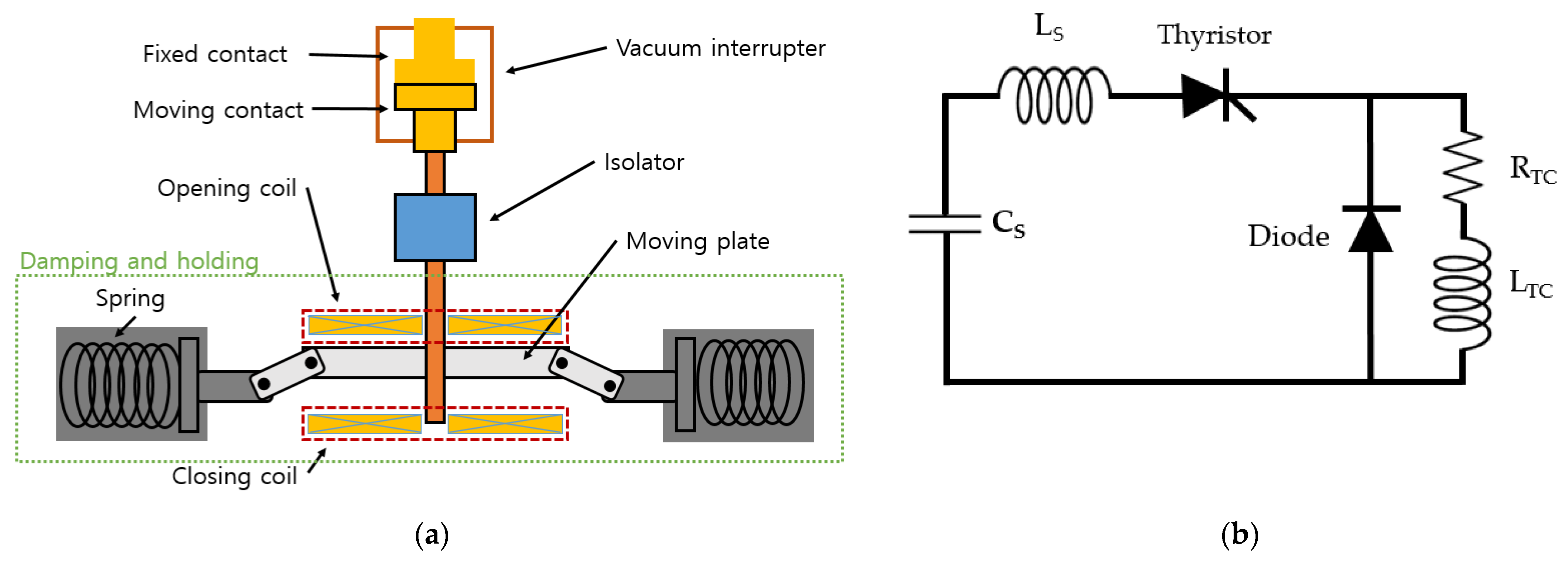
2.3. Thomson Coil Actuator Background

The TCA is a device that can separate contacts at a very high speed using electromagnetic repulsion [31,32,33,34]. The structure of the TC and the driving circuit are shown in Figure 4. As shown in the figure, the TC is divided into a damping and holding part consisting of a vacuum interrupter (VI), a Thomson coil (TC: operation coil), an operation circuit, a moving plate, and springs. An operating coil is made of a spiral conductive conductor. When the discharged current in the driving circuit is applied to the TC, the current flows along the coil and rotates. This rotational current generates a magnetic field. This magnetic field generates an eddy current in a moving plate made of metal materials such as copper or aluminum. The eddy current creates a strong repulsive force by generating a magnetic field in the opposite direction to the magnetic field generated by the coil. The moving plate can be operated quickly due to strong force. When the movable plate is pushed, the moving contact of VI connected to the movable plate moves. At this time, the current is isolated inside VI. VI contact point moves as much as the selected moving gap. A spring is used to fix the moving plate so that it does not move. An isolator is used to isolate electrically between the VI and the moving plate. The isolator separates the current passing through VI from the TC driving current so that it does not affect it.

3. Circuit Breaker Modeling

The mechanism of the mechanical switch Z-source DCCB is explored in this section. First, we describe how the proposed ZCB works. Second, an approximate analytical model of the current to the switch during a fault is derived as a function of the source voltage and passive component values. Third, an expression is derived for the relationship between the artificial current zero-crossing times t1 and t2 of the Z-source and the passive components. Finally, for the finite element method (FEM) analysis of the TC, the peak value of the current applied to the TC is derived and expressed by the equation.

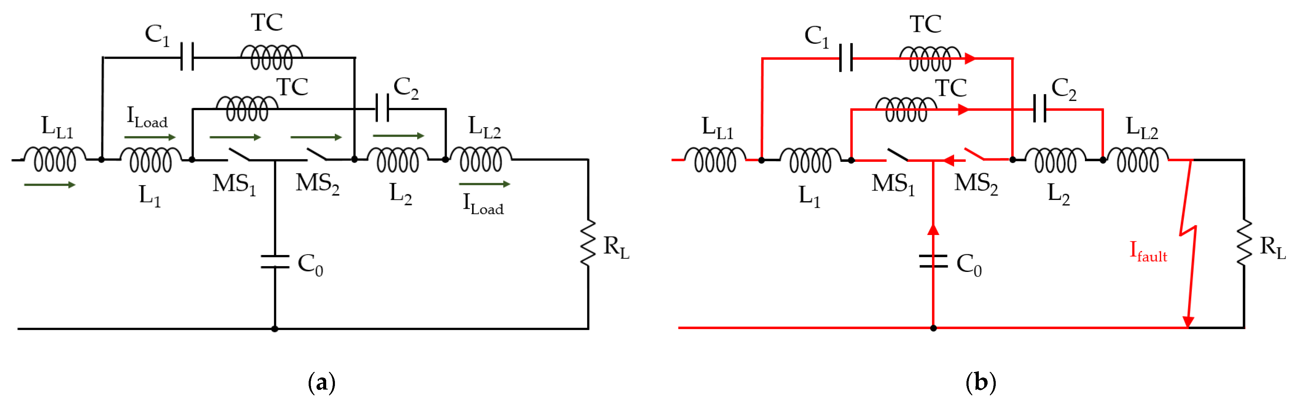
3.1. Proposed Z-Source Circuit Breaker with Mechanical Switch

The operation time of the fault detection sensor used in the existing method slows the operation speed of the mechanical switch. Therefore, the t2 timing must be further delayed for the circuit breaker to allow fault isolation. This increases the volume of the inductors, capacitors, circuit breaker, and the stress of the power conversion devices.
To solve this problem, we propose a model in which the driving unit of the TC is added to the circuit. This model is shown in Figure 5. At DC, the inductor is considered to be a short circuit, and the capacitor is considered to be open. At the normal state, the load current flows to LL1 − L1 − MS1 − MS2 − L2 − LL2 − RL. It is shown in Figure 5a. When a fault occurs, the inductor of the network impedance prevents the fault current from rising rapidly. At this time, the flow of the fault current is shown in Figure 5b. A fault current is immediately applied to the TC injected into this path to disconnect the MS contacts. An IC2 is introduced into the MS in a direction opposite to the load current. IC2 ensures sufficient current zero time due to the system inductor, allowing fault isolation of the circuit breaker.
The proposed method immediately operates in the event of a low-impedance fault that causes great damage to the circuit. A current sensor detects a high-impedance fault or a small current that may not move the TC contact and operates as a TC drive circuit. The proposed MS-ZCB could operate on all faults, such as low-impedance faults, where the current rises dramatically, and high-impedance faults. In addition, the fault is safely isolated through sufficient current zero-crossing time.

3.2. Current Flowing to During a Fault

We derive the current flowing through the MS during the fault and give a formula. The fault current flows through the system inductor and the impedance network capacitor for a transient period after the fault occurs. This is because the relatively large-impedance network inductor does not allow a rapid change in current. Figure 6 shows the equivalent circuit during the transition period of the MS-ZCB. In this case, it is assumed that the coil inductance LTC and the fault resistance Rf of the TC are insignificant and do not exist. In addition, it is assumed that the impedance network inductors L1 and L2 are so large that the current does not change during the transient period. To simplify the calculation, assume that capacitors C1 = C2 = C0 = C, inductors LL1 = LL2 = L, and no loss. According to Kirchhoff’s current law KCL and voltage law KVL, IC2 is as follows.
I C 2 = C 4 L · V S · sin ( t L C ) + C 12 L · V S · sin ( 3 L C t )
where IC2 is the current flowing through C2 at the time of the fault, and Vs is the source voltage.
The current flowing into the impedance network capacitor flows in the opposite direction to the load current flowing into the MS. Thus, the current flowing through the MS is as follows.
I M S = I L o a d I C 2
where ILoad is load current.

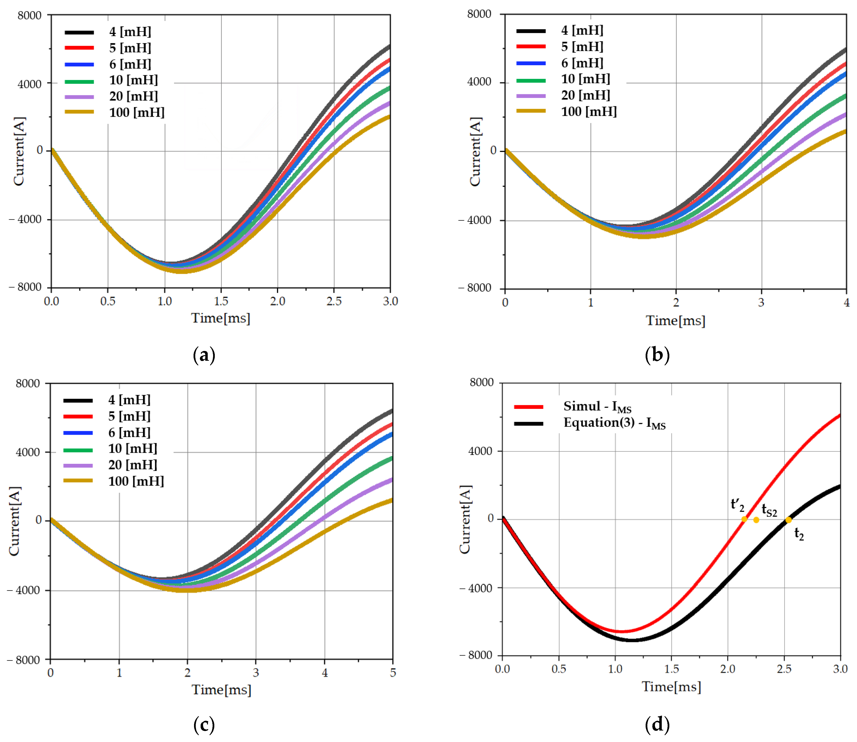
3.3. Current Zero-Crossing Time t1, t2

The current zero-crossing time t1 and t2 may be derived when IMS = 0. Therefore, the ILoad as
I L o a d = C 4 L * V S * sin ( t L C ) + C 12 L * V S * sin ( 3 L C t )
ILoad is a synthesis of two sine waves. To obtain t1 and t2, the time of each sine wave must be derived and added.
I L o a d 2 = C 4 L * V S * sin ( t a L C ) ,     I L o a d 2 = C 12 L * V S * sin ( 3 L C t b )
where ta and tb is the current zero-crossing time of each sine wave.
This is shown in order as.
t 1 a = L C * sin 1 ( L C * I L o a d V S )   , t 2 a = L C ( π sin 1 ( L C * I L o a d V S ) )   t 1 b = L C 3 * sin 1 ( 3 L C * I L o a d V S )   , t 2 b = L C 3 ( π sin 1 ( 3 L C * I L o a d V S ) )  
where, t1−a and t1−b are the first current zero crossing time, and t2−a and t2−b are the second current zero crossing time.
Therefore, t1 and t2 are as follows.
t 1 = L C 4 * sin 1 ( L C * I L o a d V S ) + L C 12 * sin 1 ( 3 L C * I L o a d V S )   t 2 = L C 4 * ( π sin 1 ( L C * I L o a d V S ) ) + L C 12 * ( π sin 1 ( 3 L C * I L o a d V S ) )
Through Equation (6), the capacitor and inductor values according to the source voltage and the speed of the MS can be derived. The properly selected capacitance and inductance create a sufficient current zero time for the MS to allow fault current isolation. At this t2, the arc of the contact is extinguished, and the fault is isolated. However, during the transition period after a fault, the magnetic field of the impedance network inductor gradually collapses. The inductor current change during the transition period changes the value of t2. To obtain a more accurate t2 time, the inductor current IL should be considered. The inductor current during the transition period is as
I L ( t ) = V S R f ( V S R f V S R l ) * exp ( R f t ( L S Y S + L e q ) )
This inductor current causes a change in t2. The amount of change in the inductor current may be derived through Equation (7) below. The difference in t2 according to the current change can be expressed as the ratio of the inductor as.
t 2 = t 2 * ( 1 L S Y S L e q + L S Y S )
where LSYS is LL1+LL2, Leq is L1 + L2, and t2 is t2 considering the change due to the impedance network inductor.

3.4. Peak Current of IC2

The maximum value of the sine wave can be obtained from the derivative of the function The derivatives of Ic2 are as
d i f f ( I C 2 ) = V S 2 L * c o s ( t p e a k L C ) + V S 2 L   * c o s ( 3 L C   * t p e a k )
where, tpeak is the time at maximum current.
The maximum current flowing through the circuit can be obtained using tpeak and Equation (1).

4. Experiment and Simulation

4.1. Mechanical Switch Z-Source Circuit Breaker Simulation

A simulation analysis of the proposed Z-source circuit breaker with a mechanical switch was conducted. Table 1 lists the ZCB parameters, where t2 is set to about 2.5 ms, 3.6 ms, and 4.42 ms at 10 kV. In addition, the changes in t2 values according to system inductance and impedance network inductance are listed. The results of the simulation with the ZCB parameters in Table 1 are shown in Figure 7. The figure shows the waveform change according to the network inductor when the system inductance is 1, 2, and 3 mH. It can be seen that as L increases, it becomes similar to the value selected in the theory. The reason is that it is assumed that the value of L is sufficiently large during the transition period. Therefore, in an actual circuit, t2 due to a change in the current IL of the network impedance inductor during a transition period must be derived. It is derived from Equation (8). The inductance and capacitance of the ZCB are calculated using (6). Figure 7d shows the comparison graph of the simulation and equation when LL = 1 mH, C = 1 mF, and L = 4 mH. In the figure, tS2 is the t2 of the simulation.

4.2. Thomson Coil Actuator Simulation

Simulations were conducted to verify that the speed of the TC used as an MS is 2.5 ms or less. For the TC simulation, FEM analysis was conducted. The current analyzed and verified in Section 3 and Section 4 was applied to the TC. IPEAK is calculated using (9). When L = 4 mH, LL = 1 mH, C = 1 mF and IPEAK = 7.1984 kA. This drive current is the same as the capacitor current IC2 in a fault. Therefore, a current of similar period and size was applied through the control of the TC driving circuit inductance and capacitance in Figure 4b. Table 2 lists the parameters of the TC drive circuit. Figure 8 shows the moving plate speed and moving distance when the charging voltage of the capacitor is 400 V. As shown in the figure, it was confirmed that the moving plate of the TC moves a distance of 10 mm within 2 ms. This means that the contact point of VI is sufficiently moved before the current zero-crossing time, enabling fault isolation.

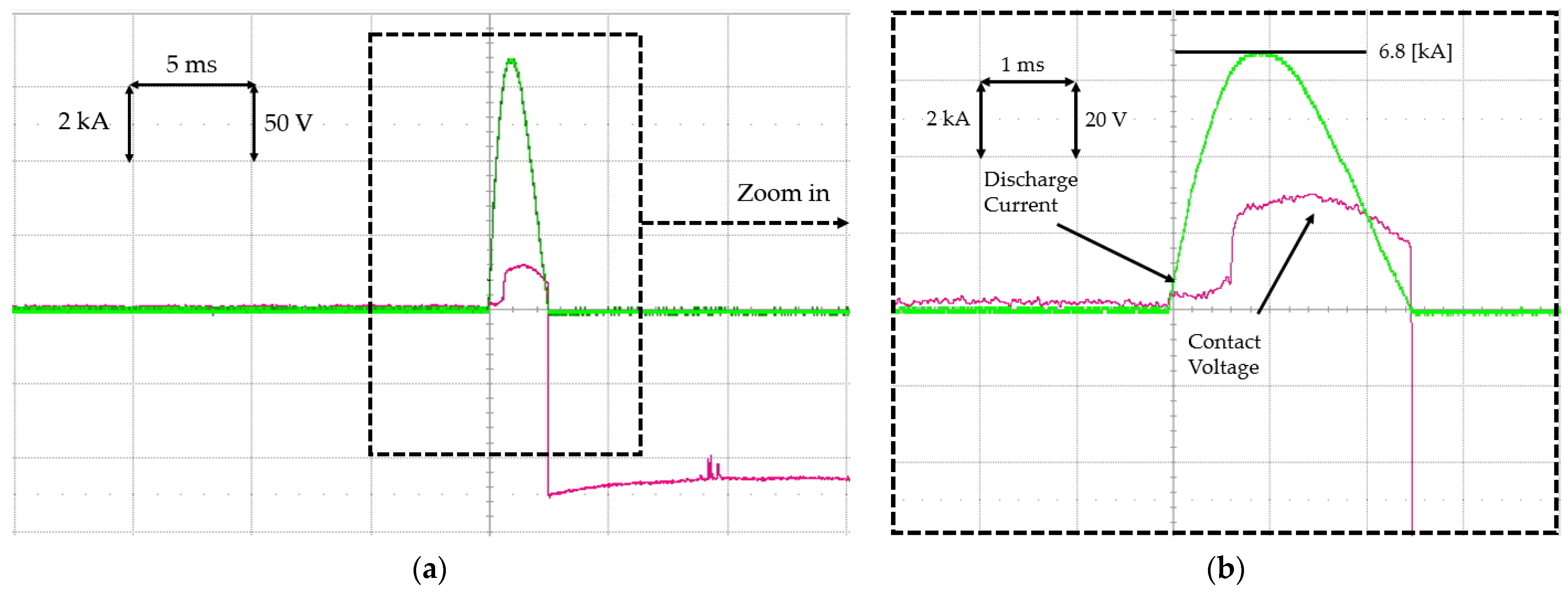
4.3. Experimental Verification and Analysis

The MS-ZCB designed at the MVDC level is difficult to design directly at the laboratory level. Therefore, in this paper, the MS-ZCB experiment is conducted in two ways. The first is a fault current application test. The previously verified fault current IC2 of the ZCB is supplied to pass through the contact point with the TC driver. The circuit is shown in Figure 9. This circuit is the same as the parameters in Table 2. When the capacitor of Figure 9b is discharged, a fault current of 6.8 kA flows in the circuit. At this time, the TC, which is a mechanical switch, operates immediately to isolate the fault. Figure 10 shows the contact voltage between the discharge current and VI in this experiment. The contact voltage in Figure 10 is the arc voltage. This arc voltage is cut off at the current zero. The capacitor is charged in reverse and discharged after discharging. As the arc is disconnected at the current zero, it shows that the voltage is −125 V inverted after the disconnection. It is the voltage charged in the capacitor. The voltage of the capacitor measured at the contact means complete isolation. The result of the fault current application test means that the proposed MS-ZCB can be detected and operated quickly.
However, a second experiment is conducted for clearer results. All DC power is continuously applied to the load. Accordingly, an operation of the MS-ZCB is tested when a fault occurs in a load to which continuous DC power of 600 V is applied. The setup of this device is shown in Figure 11. In Figure 11a, TR is a 1:2 transformer, Rec is a bridge rectifier, and CF and LF are a filter capacitor and an inductor. The filter capacitance and inductance are large enough to transmit a stable DC. Therefore, when AC 220 V commercial power is applied to the power source, a stable DC 620 V is output. In this circuit, the actual measured voltage on the load side is 550 V due to the voltage drop of the input side resistor. The ZCB of Figure 11b is connected to the rear of this circuit. The MS-ZCB parameters used in the experiment are LL = 1 mH, L = 4 mH, C = 1 mF, RL = 180 Ω, Vs = 550 V, and Rf = 1 Ω. The fault current of 600 V is not sufficient to move the moving plate. Therefore, when a fault occurs, the current in Figure 10 is applied to the TC from the TC operation circuit in Figure 4b. In this case, the TC and VI are insulated by isolators and do not affect each other. The fault current flows in the MS in a direction opposite to the load current, and a current zero is generated. The experimental results are shown in Figure 12. The point where the arc voltage rises sharply in the figure is the point where the arc is extinguished. This time is 2.09688 ms. All of these experimental results are consistent with theoretical, simulation validation results. In addition, the results of Figure 10 and Figure 12 demonstrated the effectiveness of the proposed MS-ZCB in the MVDC level system.

5. Conclusions

In this paper, a new ZCB model is proposed to improve the slow speed of MS switches. The proposed Z-source circuit breaker with a mechanical switch increases the normal-state efficiency, breaking capacity, allowable current, and circuit stability. It works immediately in faults that are feared to cause major damage, such as low-impedance faults. This allows rapid fault isolation by reducing the delay time and operation time of the sensing circuit. In addition, it provides a common ground for the load, power supply device, and can disconnect the circuit when the user wants. The calculation of components and the interruption of the fault current have been mathematically analyzed. This circuit breaker has been validated through several simulations and experiments. The experiment was conducted in two ways. The first is a 10 kV level fault current application experiment. The second is an isolation experiment when a load-side fault occurs in a continuous DC power supply. In this case, the parameters of the MS-ZCB are LL = 1 mH, L = 4 mH, C = 1 mF, and Rf = 1 Ω. The t2 measured in this experiment is 2.1 ms. The results show that the breaker is capable of fault separation within 2.5 ms at 10 kV. The higher the source voltage, the higher the fault current. When a fault occurs, the current flowing through the TC is increased to isolate the fault more quickly. Therefore, the proposed MS-ZCB is expected to be sufficiently usable even at voltages above 10 kV simulated and validated in this paper.

Author Contributions

Conceptualization, H.-S.L.; Methodology, H.-S.L.; Formal analysis, H.-S.L.; Investigation, Y.-M.C.; Resources, Y.-M.C. and K.-A.L.; Writing—original draft, H.-S.L.; Writing—review & editing, K.-A.L. and J.-H.R.; Supervision, K.-A.L.; Funding acquisition, J.-H.R. All authors have read and agreed to the published version of the manuscript.

Funding

This work was supported by the National Research Foundation of Korea(NRF) grant funded by the Korea government(MSIT) (No. RS-2022-00166064).

Conflicts of Interest

The authors declare no conflict of interest.

References

  1. Hou, L.; Chen, D.; Li, T.; Zhao, M.; Ren, H. Design and Research on DC Electric Leakage Protection Circuit Breaker. Energies 2022, 15, 5605. [Google Scholar] [CrossRef]
  2. Raghavendra, V.I.; Banavath, S.N.; Thamballa, S. Modified Z-Source DC Circuit Breaker with Enhanced Performance during Commissioning and Reclosing. IEEE Trans. Power Electron. 2022, 37, 910–919. [Google Scholar] [CrossRef]
  3. Cairoli, P.; Dougal, R.A. New horizons in dc shipboard power systems: New fault protection strategies are essential to the adoption of dc power systems. IEEE Electrif. Mag. 2013, 1, 38–45. [Google Scholar] [CrossRef]
  4. Teng, S.; Zhang, Z.; Xiao, L. Research on a novel DC circuit breaker based on artificial current zero-crossing. IEEE Access 2020, 8, 36070–36079. [Google Scholar] [CrossRef]
  5. Al-Khafaf, H.; Asumadu, J. Efficient protection scheme based on y-source circuit breaker in bi-directional zones for mvdc micro-grids. Inventions 2021, 6, 18. [Google Scholar] [CrossRef]
  6. Hategekimana, P.; Ferre, A.J.; Bernuz, J.M.R.; Ntagwirumugara, E. Fault Detecting and Isolating Schemes in a Low-Voltage DC Microgrid Network from a Remote Village. Energies 2022, 15, 4460. [Google Scholar] [CrossRef]
  7. Barnes, M.; Vilchis-Rodriguez, D.; Pei, X.; Shuttleworth, R.; Cwikowski, O.; Smith, A. HVDC Circuit Breakers-A Review. IEEE Access 2020, 8, 211829–211848. [Google Scholar] [CrossRef]
  8. Franck, C.M. HVDC circuit breakers: A review identifying future research needs. IEEE Trans. Power 2011, 26, 998–1007. [Google Scholar] [CrossRef] [Green Version]
  9. Pei, X.; Cwikowski, O.; Vilchis-Rodriguez, D.S.; Barnes, M.; Smith, A.C.; Shuttleworth, R. A review of technologies for MVDC circuit breakers. In Proceedings of the IECON Annual Conference of the IEEE Industrial Electronics Society, Toronto, ON, Canada, 13–16 October 2016. [Google Scholar] [CrossRef]
  10. Mokhberdoran, A.; Carvalho, A.; Leite, H.; Silva, N. A review on HVDC circuit breakers. In Proceedings of the Renewable Power Generation Conference, Naples, Italy, 24–25 September 2014. [Google Scholar] [CrossRef]
  11. Wu, Y.; Hu, Y.; Wu, Y.; Rong, M.; Yi, Q. Investigation of an active current injection DC circuit breaker based on a magnetic induction current commutation module. IEEE Trans. Power Deliv. 2018, 33, 1809–1817. [Google Scholar] [CrossRef]
  12. Shi, Z.Q.; Zhang, Y.K.; Jia, S.L.; Song, X.C.; Wang, L.J.; Chen, M. Design and numerical investigation of a HVDC vacuum switch based on artificial current zero. IEEE Trans. Dielectr. Elect. Insul. 2015, 22, 135–141. [Google Scholar] [CrossRef]
  13. Ludin, G.A.; Amin, M.A.; Matayoshi, H.; Rangarajan, S.S.; Hemeida, A.M.; Takahashi, H.; Senjyu, T. Solid-State DC Circuit Breakers and Their Comparison in Modular Multilevel Converter Based-HVDC Transmission System. Electronics 2021, 10, 1204. [Google Scholar] [CrossRef]
  14. Lumen, S.M.S.; Kannan, R.; Yahaya, N. DC circuit breaker: A comperhensive review of solid state topologies. In Proceedings of the IEEE International Conference on Power and Energy (PECon), Penang, Malaysia, 7–8 December 2020. [Google Scholar] [CrossRef]
  15. Sano, K.; Takasaki, M. A surgeless solid-state DC circuit breaker for voltage-source-converter-based HVDC systems. IEEE Trans. Ind. Appl. 2014, 50, 2690–2699. [Google Scholar] [CrossRef] [Green Version]
  16. Nguyen, V.-V.; Son, H.-I.; Nguyen, T.-T.; Kim, H.-M.; Kim, C.-K. A novel topology of hybrid HVDC circuit breaker for VSC-HVDC application. Energies 2017, 10, 1675. [Google Scholar] [CrossRef] [Green Version]
  17. Khalid, S.; Raza, A.; Alqasemi, U.; Sobahi, N.; Yousaf, M.Z.; Abbas, G.; Jamil, M. Technical Assessment of Hybrid HVDC Circuit Breaker Components under M-HVDC Faults. Energies 2021, 14, 8148. [Google Scholar] [CrossRef]
  18. Bösche, D.; Wilkening, E.; Köpf, H.; Kurrat, M. Hybrid DC Circuit Breaker Feasibility Study. IEEE Trans. Compon. Packag. Manuf. Technol. 2017, 7, 354–362. [Google Scholar] [CrossRef]
  19. Cho, Y.M.; Lee, K.A. Experimental Study on Splitter Plate for Improving the Dielectric Recovery Strength of Low-Voltage Circuit Breaker. Electronics 2020, 9, 2148. [Google Scholar] [CrossRef]
  20. Corzine, K.A.; Ashton, R.W. A new Z-source DC circuit breaker. IEEE Trans. Power Electron. 2012, 27, 2796–2804. [Google Scholar] [CrossRef]
  21. Peng, F.Z. Z-source inverter. IEEE Trans. Ind. Appl. 2003, 39, 504–510. [Google Scholar] [CrossRef]
  22. Corzine, K.A.; Ashton, R.W. Structure and analysis of the Z-source MVDC breaker. In Proceedings of the IEEE Electric Ship Technologies Symposium, Arlington, VA, USA, 4–6 April 2011. [Google Scholar] [CrossRef]
  23. Chang, A.H.; Sennett, B.R.; Avestruz, A.T.; Leeb, S.B.; Kirtley, J.L. Analysis and design of DC system protection using Z-source circuit breaker. IEEE Trans. Power Electron. 2015, 31, 1036–1049. [Google Scholar] [CrossRef]
  24. Savaliya, S.G.; Fernandes, B.G. Analysis and Experimental Validation of Bidirectional Z-Source DC Circuit Breakers. IEEE Trans. Ind. Electron. 2019, 67, 4613–4622. [Google Scholar] [CrossRef]
  25. Bhatta, S.; Zhang, Y.; Fu, R. Comparative Analysis of Power Loss Associated with Topology of Bi-Directional Z-Source Circuit Breakers. In Proceedings of the IEEE 2018 SoutheastCon 2018, St. Petersburg, FL, USA, 19–22 April 2018; pp. 1–5. [Google Scholar] [CrossRef]
  26. Ryan, D.J.; Torresan, H.D.; Bahrani, B. A bidirectional series Z-source circuit breaker. IEEE Trans. Power Electron. 2017, 33, 7609–7621. [Google Scholar] [CrossRef]
  27. Keshavarzi, D.; Ghanbari, T.; Farjah, E. A Z-source-based bidirectional DC circuit breaker with fault current limitation and interruption capabilities. IEEE Trans. Power Electron. 2016, 32, 6813–6822. [Google Scholar] [CrossRef]
  28. Bhatta, S.; Fu, R.; Zhang, Y. A New Method of Detecting and Interrupting High Impedance Faults by Specifying the Z-Source Breaker in DC Power Networks. Electronics 2020, 9, 1654. [Google Scholar] [CrossRef]
  29. Fu, R.; Bhatta, S.; Keller, J.M.; Zhang, Y. Assessment of Cable Length Limit for Effective Protection by Z-Source Circuit Breakers in DC Power Networks. Electronics 2021, 10, 183. [Google Scholar] [CrossRef]
  30. Mackey, L.; Rachi, M.R.K.; Peng, C.; Husain, I. Optimization and control of a z-source, ultrafast mechanically switched, high-efficiency dc circuit breaker. IEEE Trans. Ind. Appl. 2020, 56, 2871–2879. [Google Scholar] [CrossRef]
  31. Lim, D.K.; Woo, D.K.; Kim, I.W.; Shin, D.K.; Ro, J.S.; Chung, T.K.; Jung, H.K. Characteristic analysis and design of a Thomson coil actuator using an analytic method and a numerical method. IEEE Trans. Magn. 2013, 49, 5749–5755. [Google Scholar] [CrossRef]
  32. Wu, Y.; Wu, Y.; Rong, M.; Yang, F.; Zhong, J.; Li, M.; Hu, Y. A new Thomson coil actuator: Principle and analysis. IEEE Trans. Compon. Packag. Manuf. Technol. 2015, 5, 1644–1655. [Google Scholar] [CrossRef]
  33. Augustin, T.; Parekh, M.; Magnusson, J.; Becerra, M.; Nee, H.P. Thomson-coil actuator system for enhanced active resonant DC circuit breakers. IEEE J. Emerg. Sel. Top. Power Electron. 2021, 10, 800–810. [Google Scholar] [CrossRef]
  34. Pham, M.T.; Ren, Z.; Li, W.; Koh, C.S. Optimal design of a Thomson-coil actuator utilizing a mixed-integer-discrete-continuous variables global optimization algorithm. IEEE Trans. Magn. 2011, 47, 4163–4166. [Google Scholar] [CrossRef]
Figure 1. Bidirectional Z-source circuit breaker proposed in [27]: (a) normal conduction; (b) fault conduction.
Energies 15 08899 g001
Figure 2. Z-source circuit breaker: (a) parallel ZCB, proposed in [22]; (b) ZCB with mechanical switch, proposed in [30].
Energies 15 08899 g002
Figure 3. Comparison of current zero-crossing time t2 between non-system inductance (Red) and system inductance LL = 1 mH (Black).
Energies 15 08899 g003
Figure 4. Thomson coil actuator: (a) diagram; (b) equivalent Thomson coil operation circuit.
Energies 15 08899 g004
Figure 5. Schematic of the proposed Z-source circuit breaker with mechanical switch: (a) normal conduction; (b) fault conduction.
Energies 15 08899 g005
Figure 6. Proposed Z-source circuit breaker with mechanical switch simplified schematic.
Energies 15 08899 g006
Figure 7. Simulation of current changes due to system inductance and network inductance simulation: (a) LL = 1 mH, L = 4–100 mH, and C = 1 mF; (b) LL = 2 mH, L = 4–100 mH, and C = 1 mF; (c) LL = 3 mH, L = 4–100 mH, and C = 1 mF; (d) comparison of simulation and theory at LL = 1 mH, L = 4 mH, and C = 1 mF.
Energies 15 08899 g007
Figure 8. Plate displacement and speed simulation results: plate 10 mm movement after 2 ms when current is applied to TC.
Energies 15 08899 g008
Figure 9. Thomson coil actuator: (a) TC setup; (b) TC operation capacitor CS and inductor LS; (c) circuit diagram of TC setup. Red dotted box: matches elements in the actual configuration picture and circuit diagram.
Energies 15 08899 g009
Figure 10. Experimental results: discharge current and VI contact voltage. CS = 17.25 mF, LS = 26 µH, RTC = 0.2 Ω, LTC = 4.4 µH (a) full screen; (b) zoom-in screen.
Energies 15 08899 g010
Figure 11. Test setup: (a) 550 V DC power supply circuit diagram; (b) Z-source circuit breaker setup.
Energies 15 08899 g011
Figure 12. Experimental results: fault current and VI contact voltage. Vs = 550 V, RL = 180 Ω, Rf = 1 Ω, LL = 1 mH, L = 4 mH, and C = 1 mF.
Energies 15 08899 g012
Table 1. ZCB parameters according to network capacitance C, inductance L, and system inductance LL.
C (mF)LL (mH)L (mH)t2 (ms)t’2 (ms)
1142.552.04
52.125
62.186
102.318
202.429
1002.525
243.612.407
52.579
62.708
103.008
203.282
1003.539
344.422.526
52.763
62.947
103.4
203.843
1004.291
Table 2. Thomson coil operating circuit parameters.
VCharge (V)LS (µH)LTC (µH)CS (mF)Discharge Current (kA)
TC operating circuit400264.417.257
Publisher’s Note: MDPI stays neutral with regard to jurisdictional claims in published maps and institutional affiliations.

