Abstract
As a typical representative of the stator permanent magnet (PM) machines, the flux reversal machines (FRMs) have a simple structure, high availability of PMs, and high efficiency, making them suitable for direct drive applications. However, the PMs of the FRMs are mounted on the surface of the stator tooth, and its equivalent length of air gap is relatively large, which limits the torque increase. To improve the torque density, a novel FRM with auxiliary teeth is proposed in this paper. Half of the stator teeth are replaced by auxiliary teeth without PMs to reduce magnetic flux leakage, the number of PMs on each stator tooth is also changed. To improve the torque, the genetic algorithm is used to optimize the key design parameters to determine the optimal parameters of the machine. Finally, a finite element model is established to verify the analysis results. Compared with the conventional FRM, the torque of the proposed FRM is increased by 25.1%, the torque ripple is reduced by 24.1%, and the consumption of PMs is reduced by 24.1%. Therefore, the proposed FRM has a broader application prospect.
1. Introduction
Unlike conventional rotor PM machines with PMs on the rotor, stator PM machines have PMs and windings on the stationary stator, since the PMs do not rotate with the rotor, eliminating the need for complex fixing processes [1]. Thus, the stator PM machines overcome the problem of cooling difficulty of PM inherent in the rotor PM machines, greatly reducing the demagnetization risk of PMs, with higher reliability. At the same time, its rotor is the same simple salient pole structure as in the switched reluctance machines, which are easy to manufacture and maintain, and the robustness of the rotor is improved. These unique advantages of stator PM machines have attracted more and more research interest. Stator PM machines are mainly divided into double salient machines, switched flux machines and FRMs. As a typical stator PM machine, FRMs have been successfully applied to various high-speed or low-speed devices, such as new energy power generation [2], electric vehicles [3] and vacuum cleaners [4] due to their high fault tolerance, high reliability and fast transient response.
Since the FRMs were first proposed in 1997, many researchers have performed a lot of outstanding research work. In [5], the analytical design method of three-phase FRMs is established as a general design procedure of FRMs. The feasible pole-slot combination is provided simultaneously. In [6], based on the magnetomotive force—permeance model, the back EMF of the FRMs is analyzed by the air gap field modulation theory. The study found that the characteristics of the back EMF can be improved by selecting a reasonable magnetization method, winding arrangement, and number of rotor poles. In [7], the influence of different coil pitches on the back EMF of the FRMs is studied to increase the fundamental back EMF. In [8], FRMs with ring windings and concentrated windings were compared and analyzed. It was found that FRMs with ring windings have higher electromagnetic torque, higher power factor, higher efficiency, and lower torque ripple. In [9], a FRM with asymmetric stator teeth is proposed. The electromagnetic torque, power factor and efficiency of the machine are improved, and the torque ripple is reduced. In further research, a hybrid analytical model of the air gap magnetic field of the machine was established [10]. In [11], a doubly-fed FRM with armature windings in both stator and rotor is proposed, which has higher electromagnetic torque and higher fault tolerance. In the subsequent research, the harmonic of the air gap magnetic field of the machine was analyzed [12], and a doubly-fed FRM with consequent pole topologies was further proposed [13]. More research has focused on changing the arrangement of PMs to improve electromagnetic performance. In [14], a FRM with evenly distributed PMs is proposed. When the amount of PMs is the same, the machine has a higher average torque, lower cogging torque and torque ripple, and a higher power factor than the conventional FRM. In [15], the effect of the number of PMs on each stator tooth on the performance of the FRMs was studied. When the optimal number of PM blocks is used, the torque of the machine can be significantly improved. In [16], the electromagnetic performance of four FRMs with different numbers of PM blocks and magnetization sequences were compared. Based on this, the PM arrangement with the highest torque and highest efficiency in low-speed situations was found. In [17], a FRM with Quasi-Halbach array PMs in stator slot opening was proposed. When the copper loss is the same, the torque can be significantly improved. Furthermore, a FRM with double armature windings and Halbach array PMs in the stator slot is proposed, which has higher torque and lower torque ripple than the FRM with the same PM arrangement with single armature winding [18]. In [19], a FRM with spoke array PMs was proposed, and the key electromagnetic performance of the machine was simultaneously improved. Subsequently, the optimal number and shape of PM blocks for FRMs with spoke array PMs were studied [20], and a dual-PM spoke type FRM was further proposed [21]. In [22], a stator PM machine with both flux reversal effect and flux switching effect was proposed, which has higher electromagnetic torque, better overload capacity and higher efficiency.
The conventional FRM has a large amount of magnetic flux leakage, which greatly limits the further improvement of its torque density. The consequent pole topologies are widely used in FRMs to reduce magnetic flux leakage and increase torque. A consequent pole FRM for electric vehicle propulsion has been studied, which has higher electromagnetic torque, less consumption of PMs and better overload capacity than conventional FRM [23]. In [24], four consequent pole FRMs with different magnetization sequences and numbers of PM blocks were compared and analyzed, clearly demonstrating their advantages of high utilization of PM. In [25], a novel consequent pole FRM was proposed, which is characterized by having a higher number of iron poles on each stator tooth than that of PM blocks. Compared to conventional FRM, the machine has higher electromagnetic torque but also higher torque ripple. In [26,27], two kinds of FRMs with Halbach array PMs in the rotor slots and consequent pole PMs in the stator tooth were proposed. The electromagnetic torque of the two machines was improved, but they have larger torque ripple and weaker overload capacity. In [28], the consequent pole FRM was analyzed with biased field modulation theory, and the detailed design principles of the consequent pole FRM are given. In [29], the symmetrical characteristics of the consequent pole FRMs with concentrated windings were studied, and the rules for obtaining symmetrical flux linkage were revealed. Although the consequent pole FRMs can significantly reduce the magnetic flux leakage and reduce the consumption of PMs, it mostly has the problem of excessive torque ripple. In this paper, a novel FRM with auxiliary teeth is proposed, which reduces the torque ripple while increasing the main flux and increasing the torque, and the consumption of PMs is also reduced.
The structure of this paper is as follows. In Section 2, the topology and working principle of the machine are introduced. In Section 3, the sensitivity of optimization objective to each parameter in parametric model is analyzed, and the parameters with higher sensitivity are optimized by the multi-objective optimization method based on genetic algorithm to obtain the optimal electromagnetic torque. In Section 4, a finite element model is established to analyze the electromagnetic performance of the optimized machine and compare it with the electromagnetic performance of the conventional FRM. In Section 5, the full text is summarized, and the conclusion is drawn.
2. Topology and Operation Principle
2.1. Topology
The topology of the conventional FRM and the proposed machine is shown in Figure 1. The conventional FRM is equipped with two PM blocks on each stator tooth. The proposed machine is changed to three PM blocks on each stator tooth, and half of the iron teeth are changed to auxiliary teeth without PMs. The final topology is shown in Figure 1b. Because the pole pairs of the PM of the proposed machine is 12, and the number of iron teeth is also 12, the working principle is closer to the 12-slot FRM, so the 12-slot conventional FRM was chosen for comparison, and the classic topology of 12 slots and 17 teeth is adopted, as shown in Figure 1a.
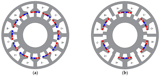
Figure 1.
The topology of machines. (a) Conventional model; (b) proposed model.
2.2. Operation Principle
The operation principle of FRM can be explained by magnetic field modulation theory. The PM on the stator produces the static magnetomotive force, and the magnetomotive force produces the rotating air gap magnetic flux density through the modulation effect of the rotor tooth, and then obtains the changing PM flux linkage in the winding. With the rotation of the rotor, the magnetic circuit changes with the change of the rotor position, the change of the magnetic circuit brings the change of the magnitude and direction of the magnetic flux in the winding, and the no-load back EMF is induced accordingly. The open-circuit field distributions at different electrical angles in an electrical cycle is shown in Figure 2. During this period, the magnetic flux of each phase winding is reversed.
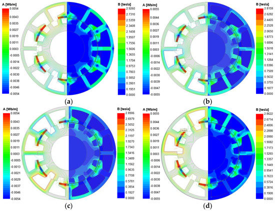
Figure 2.
Open-circuit field distributions of FRMs at different rotor positions. (a) Electrical angle 0°; (b) electrical angle 90°; (c) electrical angle 180°; (d) electrical angle 270°.
According to magnetic field modulation theory, the number of rotor tooth Nr, the number of stator slot Ns and the number of winding pole-pairs P of the FRM should satisfy:
where n = 1, 2, 3,…, m = 1, 2, 4, 5,…,k, k ≠ 3i (i = 1,2,3,…), j = 1,3,5,….
3. Parametric Optimization
To obtain a larger average electromagnetic torque and smaller torque ripple, multi-objective optimization is used to optimize the parameters. The maximum average of the torque and the minimum torque ripple are selected as the optimization objectives. The designed multi-objective optimization function f(xi) can be defined as:
where fTem(xi) and fTpkavg(xi) are the functions of the design parameter xi, which represent the electromagnetic torque and torque ripple of the machine when xi takes a certain value, Tem0 and Tpkavg0 represent the optimized initial values of electromagnetic torque and torque ripple of the machine, respectively, λ1 and λ2 are the weight coefficient, λ1 is 0.6, λ2 is 0.4, satisfying λ1 + λ2 = 1.
Therefore, according to the optimization goal we selected as the maximum average torque and the minimum torque ripple, it is necessary to find the maximum value f(xi)max of the multi-objective optimization function f(xi).
In order to fairly compare the performance of the two machines, the dimensions, current excitation, speed and material of the proposed machine and the conventional FRM were determined prior to optimization and are identical, as listed in Table 1. Then, under the determined constraints of machine size, the complete parametric model of the proposed machine and the conventional FRM is first established, as shown in Figure 3.

Table 1.
Design parameters of the machine.
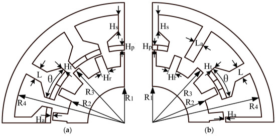
Figure 3.
Parameterized model of the conventional FRM and the proposed machine. (a) Conventional model; (b) proposed model.
To ensure the accuracy of the optimization and save the time of optimization, the sensitivity of the optimization objective to all parameters is analyzed, and the influence of the parameters on the optimization objective is obtained. The parameters with high sensitivity are selected and the experimental matrix based on CCD method was established. The resulting response values are fitted and the mathematical model of the response surface of the optimization objective is obtained. Then, the parameters are optimized based on a genetic algorithm. The flow chart of the optimization process is shown in Figure 4.
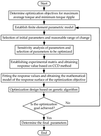
Figure 4.
Flow chart of optimization.
The genetic algorithm is designed according to the laws of natural selection and biological evolution in nature, which is characterized by simulating natural evolution to search for the optimal solution. When solving combinatorial optimization problems with many parameters, the genetic algorithm can usually obtain better optimization results more quickly. The results of multi-objective optimization based on genetic algorithm are shown in Figure 5, and the optimal parameters of the machine are finally determined. The initial value, range and final values of all parameters of the two machines are listed in Table 2.
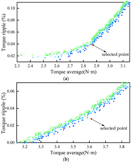
Figure 5.
Optimization results of the machines. (a) Conventional model; (b) proposed model.
Table 2.
Initial value, variation range and final value of parameters.
4. Comparison of Electromagnetic Performance
4.1. Flux Density
The radial air gap flux density of the two machines is shown in Figure 6a. The amplitude of the flux density of the proposed FRM is 1.011 T, which is smaller than 1.223 T of the conventional FRM. The reason is that the number of PMs used in the proposed machine is smaller than that of the conventional FRM, and the magnetomotive force provided by PMs is reduced. However, the proposed FRM weakens the flux leakage, and the effective air gap length of its magnetic circuit is smaller, so the amplitude of its no-load flux linkage is higher than that of the conventional FRM, as shown in Figure 7. The amplitude of the flux linkage of the proposed machine is 0.0148 Wb, which is 29.8% higher than that of the conventional FRM 0.0114 Wb. The harmonic spectra of the radial air gap flux density are shown in Figure 6b. The main harmonics of conventional FRM are the 5th, 12th, 24th, 29th and 48th. The main harmonics of the proposed FRM are 5th, 12th, 18th, 24th, 29th, 46th and 48th. The proposed machine has richer harmonics.
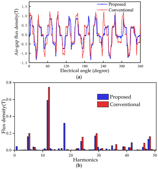
Figure 6.
Radial flux density in the air gap of the conventional FRM and the proposed machine. (a) Flux density distribution; (b) harmonic spectra.
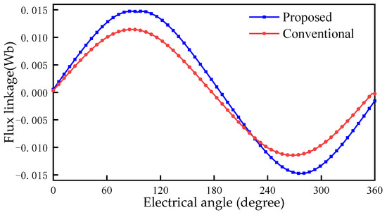
Figure 7.
Flux linkage of the conventional FRM and the proposed machine.
4.2. Back EMF
The waveform of the back EMF of the conventional FRM and the proposed machine in an electrical period is shown in Figure 8. The proposed machine has a higher amplitude of back EMF. The amplitude of back EMF of the proposed machine is 23.2 V, and the amplitude of back EMF of the conventional FRM is 18.8 V, an increase of 23.4%. Meanwhile, the degree of waveform distortion relative to the sine wave can be measured by the total harmonic distortion (THD) rate. The higher the degree of waveform distortion relative to the sine wave, the greater the THD of the back EMF, expressed as:
where Bδ is the amplitude of each harmonic, and i is the harmonic order.
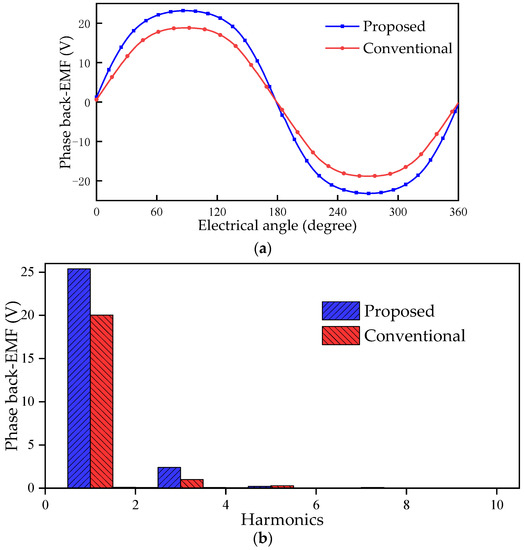
Figure 8.
Back EMF of the conventional FRM and the proposed machine. (a) Waveform; (b) harmonic spectra.
The THD of the proposed machine is 9.78%, which is higher than 5.38% of the conventional FRM. Therefore, the back EMF of the conventional machine is more sinusoidal than that of the proposed machine.
4.3. Torque
According to the Maxwell stress tensor method [30], the torque expression is as follows,
where Lef is the effective axial length, Re is the radius of the air gap, μ0 is the permeability of the vacuum, Bt and Br are tangential the and radial magnetic flux density.
The torque ripple can be measured by the torque ripple coefficient Tpkavg. Tpkavg defined as:
where Tmax is the maximum torque, Tmin is the minimum torque and Tavg is the average torque.
The electromagnetic torque of the conventional FRM and the proposed machine in an electrical cycle is shown in Figure 9. The Tem of the proposed machine is 3.59 N·m, 25.1% higher than the 2.87 N·m of the conventional FRM. The proposed FRM has a higher torque density, so it can have a larger output in a limited volume. The consumption of PMs of the machine is reduced by 24.1%. This indicates that the machine can produce greater electromagnetic torque per unit volume of PM. At the same time, the Tpkavg of the conventional FRM is 3.49%, the Tpkavg of the proposed machine is 2.65%, and the Tpkavg is reduced by 24.1% for the proposed machine.
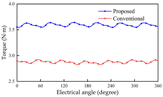
Figure 9.
Electromagnetic torque of the conventional FRM and the proposed machine.
4.4. Overload Capability
To analyze the difference in overload capacity between the two machines, the electromagnetic torque and current curve is shown in Figure 10. The proposed machine is easier to reach saturation than the conventional FRM, which means that its overload capacity is weaker than the conventional machine. The main reason is that the equivalent air gap length of the magnetic circuit of the proposed machine is smaller, and a stronger armature reaction occurs. However, the proposed machine can still produce higher torque in a wide load range, which is suitable for occasions with higher requirements for torque density.
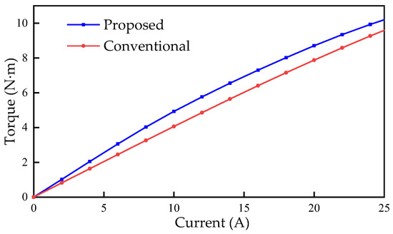
Figure 10.
Torque versus current curves of the conventional FRM and the proposed machine.
4.5. Power Factor
Based on the phasor diagram under Id = 0 control in Figure 11, the power factor can be obtained [14]:
where ωe is the electrical angular speed, Ls is the synchronous inductance, Is is the stator current, E0 is the back EMF, Rs is the stator resistance, Ψm is the no load phase flux linkage, U is the terminal voltage, and θ is the angle different between U and E0.
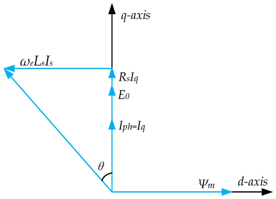
Figure 11.
Phasor diagram of the FRM machines under Id = 0.
The values of phase flux linkage, synchronous inductance, phase winding voltage drop, and power factor are listed in Table 3. The PF of the proposed machine is 0.7456, which is 0.95% lower than that of the conventional FRM 0.7526, and there is no significant difference between the two machines. The main reason is that the proposed machine has a larger flux linkage but also a larger synchronous inductance.
Table 3.
The values of phase flux linkage, synchronous inductance, and power factor.
4.6. Loss and Efficiency
The loss of the PM machine is mainly copper loss, core loss and eddy current loss. The waveform of copper loss, core loss and eddy current loss of the conventional FRM and the proposed machine are shown in Figure 12, Figure 13 and Figure 14, respectively.
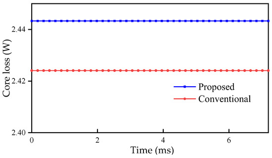
Figure 12.
Copper loss of the conventional FRM and the proposed machine.
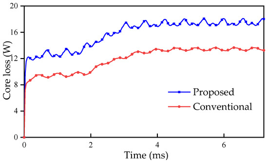
Figure 13.
Core loss of the conventional FRM and the proposed machine.
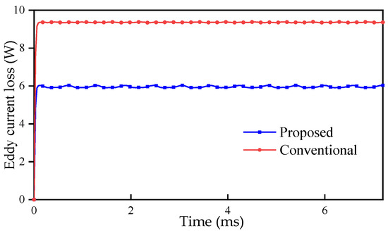
Figure 14.
Eddy current loss of the conventional FRM and the proposed machine.
The copper loss of the proposed machine is 2.443 W, while that of the conventional FRM is 2.424 W. The difference between the two is very small.
The core loss of the proposed machine is 18.105 W, while that of the conventional FRM is 13.665 W. The proposed machine has greater core loss.
The eddy current loss of the proposed machine is 6.035 W, while that of the conventional FRM is 9.389 W. The eddy current loss of the proposed machine is smaller, mainly because the proposed machine has less consumption of PM.
The efficiency η of the machine can be calculated according to the following formula:
where P is the output power, Pcopper is the copper loss, Pcore is the core loss, Peddy is the eddy current loss, and Padd is other additional losses, including friction loss, etc., and is estimated to be 2% of the output power in the calculation.
Various losses, output power and efficiency are listed in Table 4. The total loss of the proposed machine is 34.1 W and the total loss of the conventional FRM is 31.5 W. Although the proposed machine has a larger total loss, the output power is significantly improved at the same time because its output torque is significantly increased, and the efficiency of the proposed machine is still 91.68%. Compared to the 90.51% efficiency of conventional FRM, the proposed machine still has higher efficiency.
Table 4.
Various losses, output power and efficiency.
5. Conclusions
In this paper, a novel FRM with auxiliary teeth is proposed and the parameters of the machine are optimized based on a genetic algorithm to improve the torque. The electromagnetic characteristics of the proposed FRM and conventional FRM are analyzed and compared. The results show that the proposed machine significantly reduces the magnetic flux leakage and increases the amplitude of flux linkage and back EMF. The proposed machine reduces the consumption of PMs by 24.1% and obtains an average torque increase of 25.1% and a torque ripple decrease of 24.1%. The machine is easier to reach saturation than conventional FRM, but it can still provide greater electromagnetic torque under different load conditions. In addition, the total loss of the proposed machine is slightly higher than that of the conventional machine, but it still has higher efficiency due to its larger output power.
Therefore, compared with the conventional FRM, the proposed FRM is an attractive design, which can effectively improve the performance of the machine.
Author Contributions
Propose research content and design scheme, L.J.; Modeling analysis and writing, K.Y.; Overall check, Y.G.; Validation, Z.K. and Z.M.; writing—review and editing, Z.M. and Z.K. All authors have read and agreed to the published version of the manuscript.
Funding
This research received no external funding.
Conflicts of Interest
The authors declare no conflict of interest.
References
- Jing, L.; Pan, Y.; Wang, T.; Qu, R.; Cheng, P. Transient Analysis and Verification of a Magnetic Gear Integrated Permanent Magnet Brushless Machine with Halbach Arrays. IEEE J. Emerg. Sel. Top. Power Electr. 2022, 10, 1881–1890. [Google Scholar] [CrossRef]
- Manne, B.; Kiran Kumar, M.; Akuru, U.B. Design and Performance Assessment of a Small-Scale Ferrite-PM Flux Reversal Wind Generator. Energies 2020, 13, 5565. [Google Scholar] [CrossRef]
- Gao, Y.; Qu, R.; Li, D.; Li, J. Torque Performance Analysis of Three-Phase Flux Reversal Machines. IEEE Trans. Ind. Appl. 2017, 53, 2110–2119. [Google Scholar] [CrossRef]
- Dmitrievskii, V.; Prakht, V.; Kazakbaev, V.; Sarapulov, S. Optimal Design of a High-Speed Single-Phase Flux Reversal Motor for Vacuum Cleaners. Energies 2018, 11, 3334. [Google Scholar] [CrossRef]
- Gao, Y.; Li, D.; Qu, R.; Li, J. Design Procedure of Flux Reversal Permanent Magnet Machines. IEEE Trans. Ind. Appl. 2017, 53, 4232–4241. [Google Scholar] [CrossRef]
- Zhu, X.; Hua, W.; Wang, W.; Huang, W. Analysis of Back-EMF in Flux-Reversal Permanent Magnet Machines by Air Gap Field Modulation Theory. IEEE Trans. Ind. Electron. 2019, 66, 3344–3355. [Google Scholar] [CrossRef]
- Hua, W.; Zhu, X.; Wu, Z. Influence of Coil Pitch and Stator-Slot/Rotor-Pole Combination on Back EMF Harmonics in Flux-Reversal Permanent Magnet Machines. IEEE Trans. Energy Convers. 2018, 33, 1330–1341. [Google Scholar] [CrossRef]
- Li, H.; Zhu, Z.Q.; Hua, H. Comparative Analysis of Flux Reversal Permanent Magnet Machines with Toroidal and Concentrated Windings. IEEE Trans. Ind. Electron. 2020, 67, 5278–5290. [Google Scholar] [CrossRef]
- Yang, H.; Lin, H.; Zhu, Z.Q.; Lyu, S.; Liu, Y. Design and Analysis of Novel Asymmetric-Stator-Pole Flux Reversal PM Machine. IEEE Trans. Ind. Electron. 2020, 67, 101–114. [Google Scholar] [CrossRef]
- Liu, W.; Yang, H.; Lin, H.; Qin, L. Hybrid Analytical Modeling of Air-Gap Magnetic Field in Asymmetric-Stator-Pole Flux Reversal Permanent Magnet Machine Considering Slotting Effect. IEEE Trans. Ind. Electron. 2022, 69, 1739–1749. [Google Scholar] [CrossRef]
- Wu, L.; Zheng, Y.; Fang, Y.; Huang, X. Novel Fault-Tolerant Doubly Fed Flux Reversal Machine with Armature Windings Wound on Both Stator and Rotor Teeth. IEEE Trans. Ind. Electron. 2021, 68, 4780–4789. [Google Scholar] [CrossRef]
- Zheng, Y.; Wu, L.; Li, H.; Wen, H.; Qiu, L. Harmonic Analysis of Airgap Magnetic Fields in Doubly-Fed Flux Reversal Permanent Magnet Machines. IEEE Access 2020, 8, 134856–134867. [Google Scholar] [CrossRef]
- Zheng, Y.; Wu, L.; Fang, Y.; Li, T.; Zheng, W. Comparative Analysis of Doubly Fed Flux-Reversal Permanent Magnet Machines with Different PM Arrangements and Consequent-Pole Topologies. IEEE Trans. Magn. 2021, 57, 1–6. [Google Scholar] [CrossRef]
- Li, D.; Gao, Y.; Qu, R.; Li, J.; Huo, Y.; Ding, H. Design and Analysis of a Flux Reversal Machine with Evenly Distributed Permanent Magnets. IEEE Trans. Ind. Appl. 2018, 54, 172–183. [Google Scholar] [CrossRef]
- Li, H.-Y.; Zhu, Z.Q. Optimal Number of Magnet Pieces of Flux Reversal Permanent Magnet Machines. IEEE Trans. Energy Convers. 2019, 34, 889–898. [Google Scholar] [CrossRef]
- Li, H.; Zhu, Z.Q. Influence of Adjacent Teeth Magnet Polarities on the Performance of Flux Reversal Permanent Magnet Machine. IEEE Trans. Ind. Appl. 2019, 55, 354–365. [Google Scholar] [CrossRef]
- Xie, K.; Li, D.; Qu, R.; Yu, Z.; Gao, Y.; Pan, Y. Analysis of a Flux Reversal Machine with Quasi-Halbach Magnets in Stator Slot Opening. IEEE Trans. Ind. Appl. 2019, 55, 1250–1260. [Google Scholar] [CrossRef]
- Zheng, Y.; Wu, L.; Zhu, J.; Fang, Y.; Qiu, L. Analysis of Dual-Armature Flux Reversal Permanent Magnet Machines with Halbach Array Magnets. IEEE Trans. Energy Convers. 2021, 36, 3044–3052. [Google Scholar] [CrossRef]
- Qu, H.; Zhu, Z.Q. Analysis of Spoke Array Permanent Magnet Flux Reversal Machines. IEEE Trans. Energy Convers. 2020, 35, 1688–1696. [Google Scholar] [CrossRef]
- Qu, H.; Zhu, Z.Q.; Shuang, B. Influences of PM Number and Shape of Spoke Array PM Flux Reversal Machines. IEEE Trans. Energy Convers. 2021, 36, 1131–1142. [Google Scholar] [CrossRef]
- Wei, F.; Zhu, Z.Q.; Qu, H.; Yan, L.; Qi, J. New Dual-PM Spoke-Type Flux-Reversal Machines for Direct-Drive Applications. IEEE Trans. Ind. Appl. 2022, 58, 6190–6202. [Google Scholar] [CrossRef]
- Cai, S.; Chen, H.; Yuan, X.; Wang, Y.-C.; Shen, J.-X.; Lee, C.H.T. Analysis of Synergistic Stator Permanent Magnet Machine with the Synergies of Flux-Switching and Flux-Reversal Effects. IEEE Trans. Ind. Electron. 2022, 69, 12237–12248. [Google Scholar] [CrossRef]
- Gao, Y.; Qu, R.; Li, D.; Li, J.; Zhou, G. Consequent-Pole Flux-Reversal Permanent-Magnet Machine for Electric Vehicle Propulsion. IEEE Trans. Appl. Supercond. 2016, 26, 1–5. [Google Scholar] [CrossRef]
- Li, H.Y.; Zhu, Z.Q. Analysis of Flux-Reversal Permanent-Magnet Machines with Different Consequent-Pole PM Topologies. IEEE Trans. Magn. 2018, 54, 8105305. [Google Scholar] [CrossRef]
- Qu, H.; Zhu, Z.Q.; Li, H. Analysis of Novel Consequent Pole Flux Reversal Permanent Magnet Machines. IEEE Trans. Ind. Appl. 2021, 57, 382–396. [Google Scholar] [CrossRef]
- Yang, K.; Zhao, F.; Wang, Y. Analysis of Double-Layer Permanent-Magnet Flux Reversal Machines with Different Permanent Magnet Arrangements in Stator. IEEE Trans. Magn. 2021, 57, 1–5. [Google Scholar] [CrossRef]
- Yang, K.; Zhao, F.; Wang, Y.; Bao, Z. Consequent-Pole Flux Reversal Permanent Magnet Machine with Halbach Array Magnets in Rotor Slot. IEEE Trans. Magn. 2021, 57, 1–5. [Google Scholar] [CrossRef]
- Yang, H.; Zhu, Z.Q.; Lin, H.; Li, H.; Lyu, S. Analysis of Consequent-Pole Flux Reversal Permanent Magnet Machine with Biased Flux Modulation Theory. IEEE Trans. Ind. Electron. 2020, 67, 2107–2121. [Google Scholar] [CrossRef]
- Hua, H.; Zhu, Z.Q. Investigation on Symmetrical Characteristics of Consequent-Pole Flux Reversal Permanent Magnet Machines with Concentrated Windings. IEEE Trans. Energy Convers. 2022, 37, 1815–1824. [Google Scholar] [CrossRef]
- Jing, L.; Tang, W.; Wang, T.; Ben, T.; Qu, R. Performance Analysis of Magnetically Geared Permanent Magnet Brushless Motor for Hybrid Electric Vehicles. IEEE Trans. Transp. Electr. 2022, 8, 2874–2883. [Google Scholar] [CrossRef]


Publisher’s Note: MDPI stays neutral with regard to jurisdictional claims in published maps and institutional affiliations. |
© 2022 by the authors. Licensee MDPI, Basel, Switzerland. This article is an open access article distributed under the terms and conditions of the Creative Commons Attribution (CC BY) license (https://creativecommons.org/licenses/by/4.0/).