Article

A Novel High-Speed Permanent Magnet Synchronous Motor for Hydrogen Recirculation Side Channel Pumps in Fuel Cell Systems

College of Electrical and Automation Engineering, Nanjing Normal University, Nanjing 210023, China
*
Author to whom correspondence should be addressed.
Energies 2022, 15(23), 8913; https://doi.org/10.3390/en15238913
Submission received: 21 October 2022 / Revised: 20 November 2022 / Accepted: 23 November 2022 / Published: 25 November 2022
(This article belongs to the Topic Advanced Electrical Machines and Drives Technologies)

Abstract

:
In hydrogen recirculation side channel pumps, the motor rotor is exposed to a high-pressure mixture of steam and hydrogen, which makes hydrogen embrittlement occur in permanent magnets (PMs). A protective coating is necessary for the PMs in high-pressure hydrogen. However, in the process of sleeve interference installation, the protective coating of the PMs is easily damaged. This paper proposes two surface-mounted insert permanent magnet (SIPM) synchronous motor topologies, SIPM1 and SIPM2, in which the retaining sleeves can be eliminated and the PM protective coating is safe in the assembling process. A dovetail PM and rotor core structure is used to protect the PM with higher rotor strength without retaining the sleeve. The electromagnetic performance of the motors with different rotors, including airgap flux density, output torque, torque ripple, and energy efficiency is compared and optimized. It is concluded that the output torque of the SIPM motor can be promoted by 22.4% and torque ripple can be reduced by 2.9%, while the PM volume remains the same as that of the conventional SPM motor. At the same time, the SIPM motor can have lower harmonic contents of back electromotive force (EMF) and rotor loss compared to the SPM motor with a retaining sleeve. Furthermore, the stress of the PM is analyzed under conditions of PM glue action and failure. The proposed SIPM2 has the ability to operate safely at high-speed and high-temperature operating conditions when the PM glue fails.

1. Introduction

In recent years, environmentally friendly transportation and clean energy are popular topics due to depleting fossil fuel energy and concerns of environmental protection [1,2]. The availability of power-intensive and efficient electric motors plays an important role in the development and rapid implementation of hybrid electric vehicles (HEVs) [3,4]. High-speed brushless permanent magnet synchronous motors (PMSMs) have been attracting wide attention due to their high efficiency and high-power density and have been extensively applied in industrial applications such as compressors, pumps, electric vehicles, and motor tool spindle drives [5,6,7]. Hydrogen fuel cells (HFC) have been widely used in HEVs as driving motors due to their high efficiency, low environmental influence, and good renewability. It is inevitable that excess hydrogen is wasted when the HFC is working. Fortunately, it has been concluded that this problem can be optimized by adding a recycling system to the outlet side of the stack in order to collect excess hydrogen and recirculate it back to the HFC stack by the recirculation pumps (RPs) and ejector to achieve hydrogen secondary utilization [8,9]. The hydrogen system of the HFC is shown in Figure 1. Hydrogen mixed with water, which exhaust from the anode outlet of the stack, is dewatered by the water separator. Dried hydrogen then flows into the RPs and ejector for secondary electricity generation. The ejector, combined with RPs, has the following enhancements compared to ejector-only systems:
  • Wider operation range: pressure difference and flow rate;
  • Cover low power system load working condition;
  • Increased flexibility of shut-down procedure.
RPs need to be driven with a motor, and high-speed PMSMs can meet the requirements of RPs due to their advantages. In the case of special operating conditions, such as high-pressure hydrogen, the rare-earth PM material is facilely pulverized due to the fact that hydrogen atoms may enter the interior along the grain boundary of the PMs. A protective coating is necessary for the PMs in the hydrogen recirculation side channel pumps (HRSCPs). It is worth noting that PM materials are generally very weak in tension and cannot afford large centrifugal forces at high-speed operation. In order to protect the PM materials at high-speed operation, a retaining sleeve is proposed to be fixed on the outer surface of the PM materials by interference installation.
There are two existing retaining sleeve materials to protect PMs: one is to use a high-strength non-magnetic alloy sleeve, such as stainless steel, and the other is to bundle rotors with high-strength fibers, such as carbon fiber [10,11]. However, the motor’s manufacturing cost and complexity can be increased due to the introduction of a retaining sleeve. Meanwhile, the eddy current loss and poor heat dissipation capability can be introduced by non-magnetic alloy and carbon fiber, respectively. It is worth noting that the retaining sleeve relatively increases the physical airgap length, and the additional resistance can be crossed by flux lines, which leads to the reduction of output torque and efficiency [12]. Meanwhile, the protective coating of the PMs can be easily damaged in the process of sleeve interference installation. For these reasons, a sleeve-free high-speed motor is now in demand.
At present, sleeve-free is used mainly in interior permanent magnet (IPM) synchronous motors [13,14]. Reference [15] proposes to use an amorphous material for the rotor core to eliminate the need for a sleeve. The low core losses and high-strength of amorphous material are interesting properties for high-speed motors. However, there is a well-known problem of slotting that affects amorphous material during the manufacturing process. Laser cutting can cause short circuits, and the wire electrical discharge machining method is more time-consuming. A novel retaining sleeve is proposed in reference [16] to reduce eddy current loss. The sleeve opening is imposed to the surface within a range that meets mechanical safety. The losses are further reduced by adjusting the skew angle of the opening area. The sleeve eddy current losses in the optimized sleeve decreased by 72.6% compared with the initially produced model. However, the rotor retaining sleeve is not completely eliminated.
Zhao proposes an optimal design of a novel asymmetrical rotor to obtain performance improvement [17]. The proposed design of the asymmetrical rotor is employed to improve the torque characteristics by establishing rotor asymmetry to allow the reluctance torque and the magnetic torque to reach maximum. It is regrettable that Zhao only investigated the design at low speed. Reference [18] compares rotor stress in different PM installation methods, including where PMs are fixed with glue to the surface of the rotor core and installed without glue by using a retaining sleeve. Nevertheless, the glue failure condition is not taken into account when a retaining sleeve is not used to protect the PM. It is desirable to investigate whether or not the PM falls off the rotor core when the glue fails with sleeve-free.
In this paper, two novel surface-mounted insert permanent magnet (SIPM) motors are proposed to reduce the expense of a retaining sleeve and prevent the PM from falling out of the rotor core. Assessment is also conducted on electromagnetic performance, such as output torque, which can be promoted due to the elimination of the sleeve resistance. This paper is organized as follows: the topologies and main parameters of the conventional SPM motor and proposed SIPM motors are described in Section 2. In Section 3, the influence of rotor design parameters on electromagnetic performance, including back electromotive-force (EMF), output torque, and torque ripple, is investigated. Meanwhile, the rotor stress of SIPM is analyzed to help determine parameters. In Section 4, the electromagnetic and mechanical performance of the SIPM and conventional SPM motors are compared to prove the superiority of the proposed SIPM motors. Finally, Section 5 gives the conclusion. From the literature survey, there have been few technical articles that investigate the sleeve-free applications in SPM motors at high-speed rotation and special working environments, and the main contribution of this paper is to propose a promising solution to enhance the rotor strength of a sleeve-free SPM motor in HRSCPs.

2. Motors with Different Rotors

Motor windings is a key part of achieving electromechanical energy conversion, and includes the distribution windings and concentrated windings in the motor. Compared to the more complex end forms of distributed windings, concentrated windings have the advantage of simple winding ends and low resistance. In this paper, a low power motor is investigated for HRSCP, and concentrated windings with low loss can meet HRSCP’s high efficiency requirement. The SPM rotor is chosen as the rotor type instead of the IPM rotor due to the fact that SPM rotors are easily designed to optimize the air-gap flux density waveform of the motor to a sinusoidal distribution, thus improving the performance of the motor.
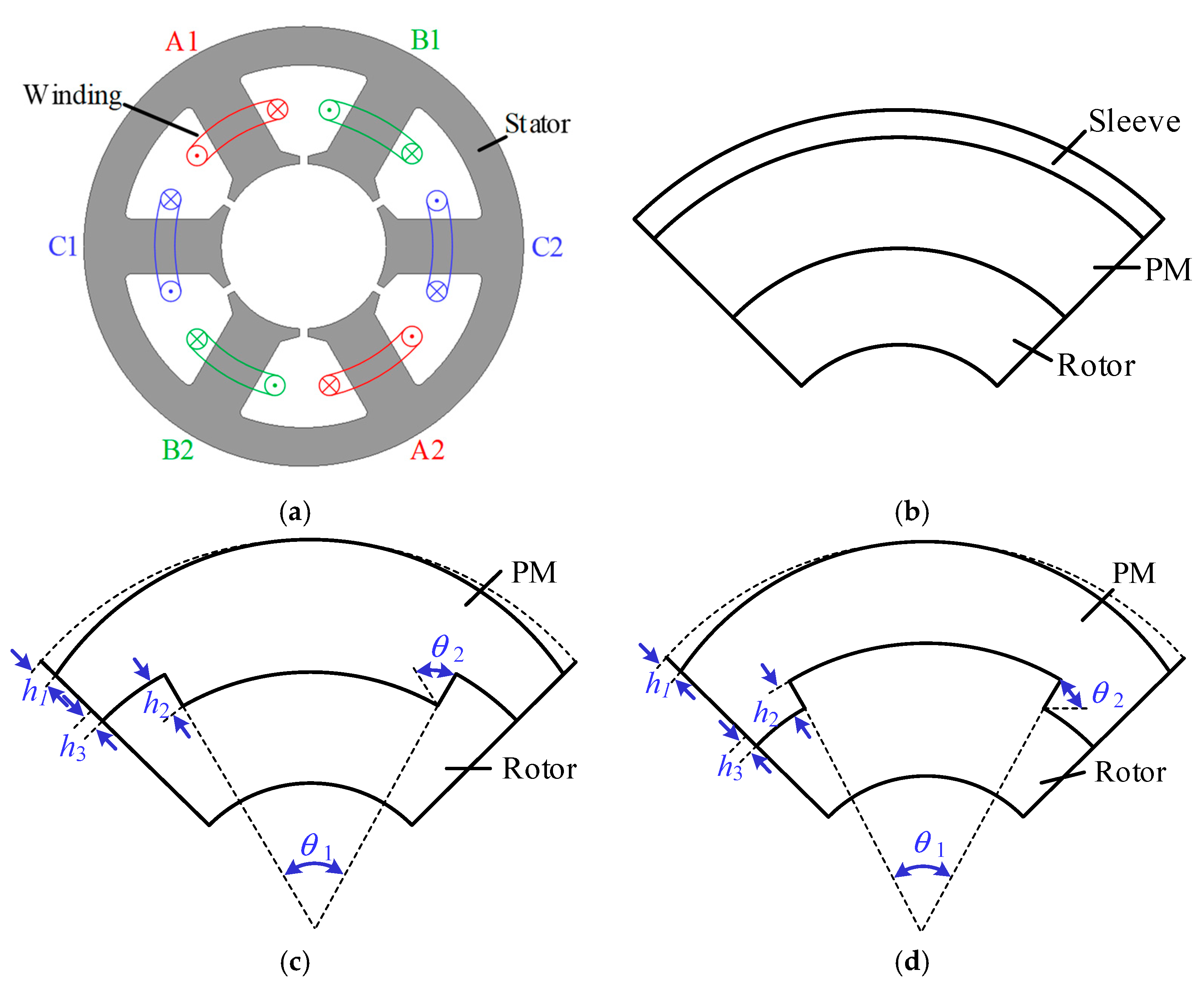
In order to compare the performance of the motors among the SPM and SIPM, the 6-slot/4-pole PMSM with fractional-slot concentrated-winding (FSCW) is adopted, as shown in Figure 2a. Figure 2b shows the conventional SPM rotor with the retaining sleeve. The detailed parametric models of SIPM rotors are shown in Figure 2c,d. It is worth noting that the motors have the same stator, axial length, and airgap length, and the main design parameters are given in Table 1. The PMs thickness of SIPM rotors is not given in Table 1 due because the shape needs to be adjusted to optimize performance. Meanwhile, the volume of PMs in the SIPM rotors is the same as that in the SPM rotor. The materials of stator, rotor, and PM are T-100, Steel-1010, and NdFeB, respectively. The thickness of the silicon steel sheet is 0.1 mm.
For high-speed range operation, the SPM rotor employs a sleeve to protect the PMs, while the SIPM rotors possess the dovetailed rotor core to implement it; the PMs are locked inside the rotor core by the slotted core. There will be additional closed leakage flux lines generated in the contact between the dovetailed PM and rotor core in the SIPM rotors, which leads to increasing harmonics order. To minimize the harmonics order, there are many alternative methods available for tackling this problem. In particular, skewing of the stator slots has been widely used to reduce cogging torque. However, the skewing of stator slots is difficult and can therefore increase production costs. In this paper, the harmonics order is weakened by changing the shape of the magnet poles [19,20].

3. Parametric Optimization of SIPM Motors

In order to optimize the electromagnetic performance and reliability of the mechanical structure and avoid the geometric conflict, four key design parameters of the SIPM rotors are chosen for the performance optimizations, and their range of variations are listed in (1).
{ 20 ° θ 1 70 ° 0 ° θ 2 60 ° 0   mm h 1 1.5   mm 0.5   mm h 2 1.5   mm .
The volume of PMs in three rotors keep the same by adjusting h3, thus, h3 is not given a range of variations.

3.1. Electromagnetic Optimization of SIPM

Maxwell software is adopted to analyze the electromagnetic performance of the conventional SPM and the proposed SIPM motors, including field distribution, back-EMF, torque characteristics, and loss. The no-load back-EMF and torque characteristics are selected as the design objectives of SIPM motors in this section.
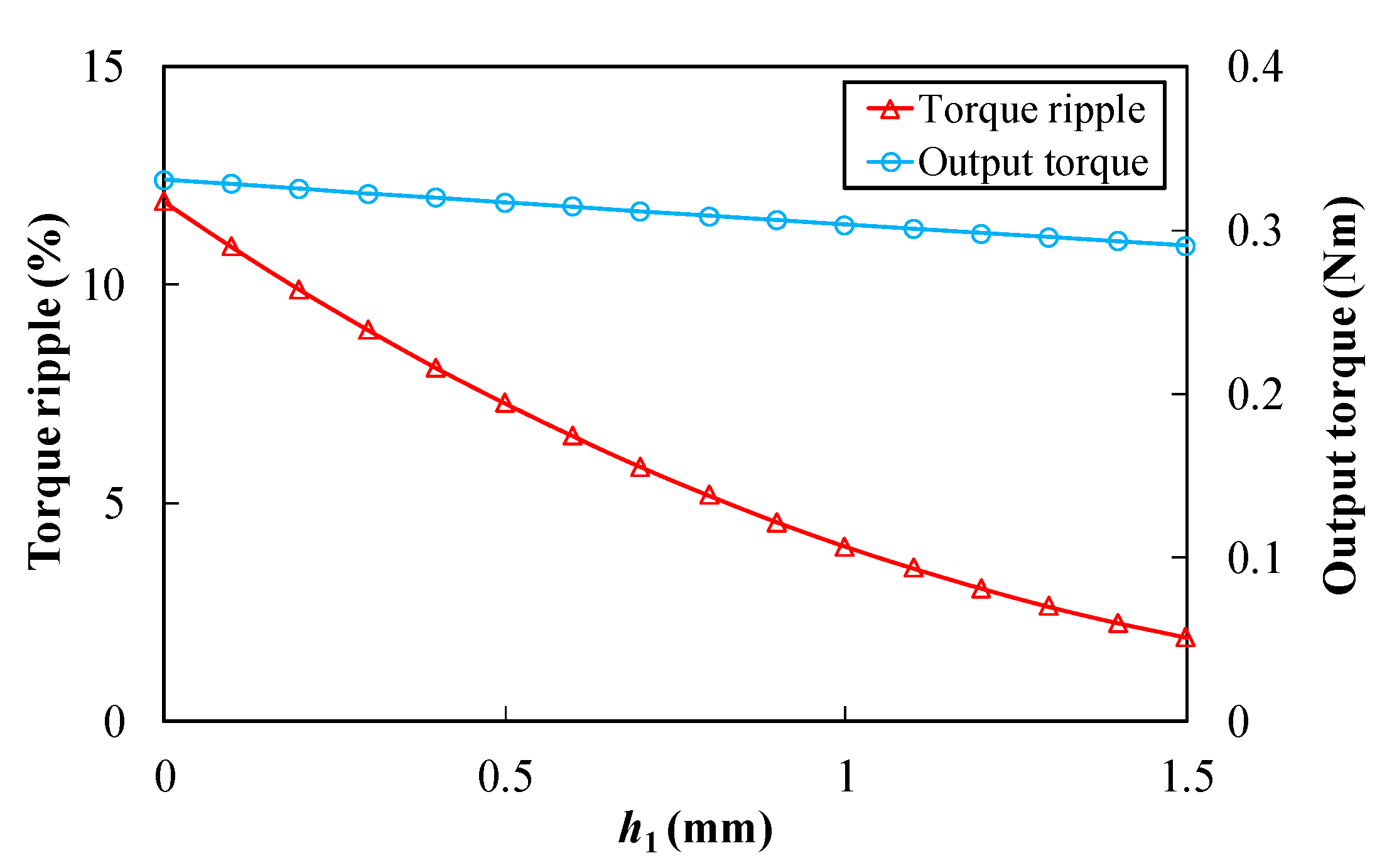
Figure 3 shows the variations of output torque and torque ripple, with trimming thickness h1 of the PMs edge in the SPM motor without sleeve. Apparently, both output torque and torque ripple decrease with h1. However, the decrease in torque ripple is much smaller than that of output torque, which demonstrates that the adopted shape of the magnet poles can effectively weaken the torque ripple with a slight sacrifice of output torque.
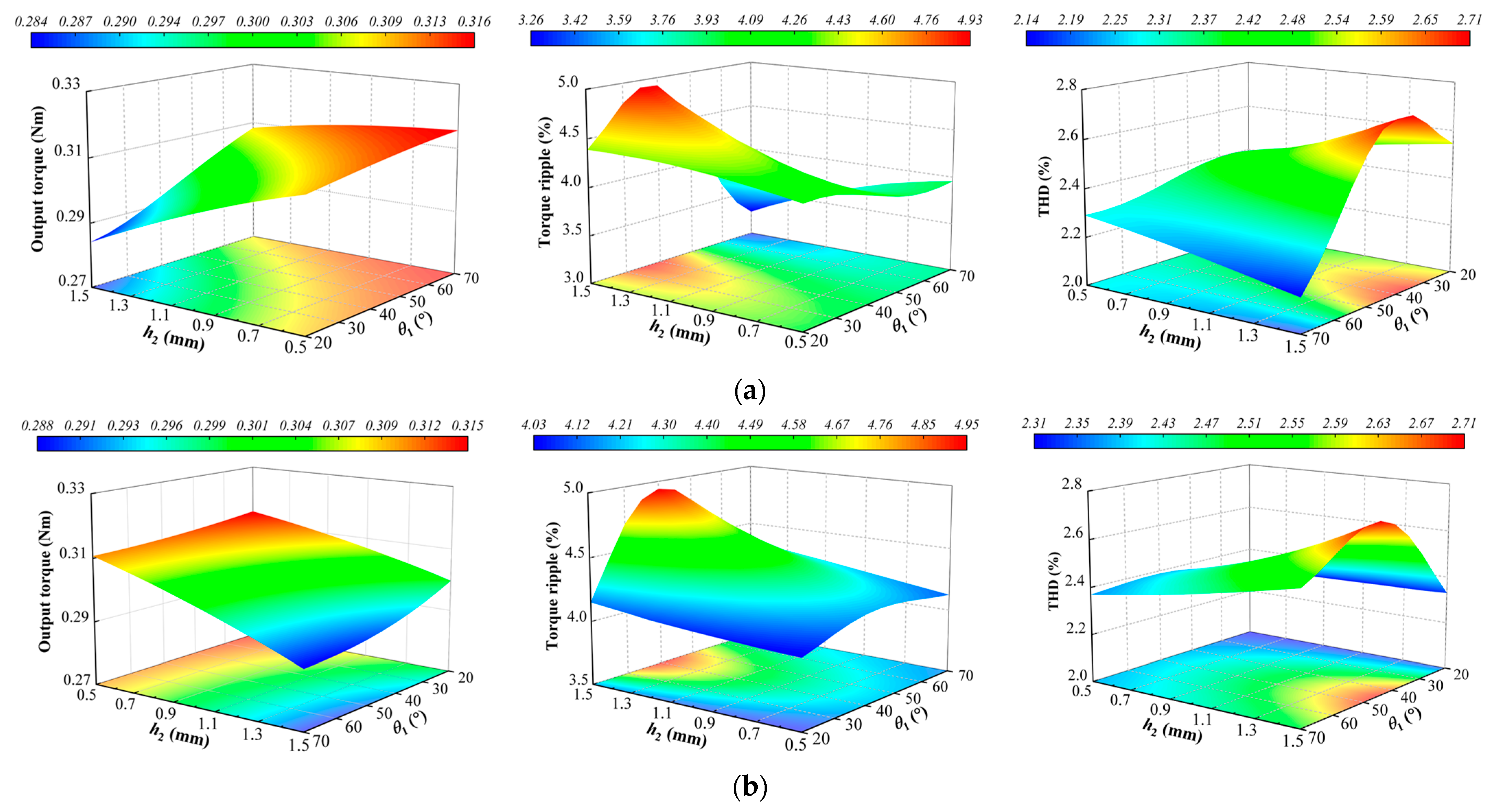
Figure 4 shows that FE predicted the three-dimensional (3-D) view of the output torque, torque ripple, and total harmonic distortion (THD) of no-load EMF with h2 and θ1 at the rated current and speed. THD is defined as
T H D = n = 2 E n 2 E 1
where En is the amplitude of the no-load EMF harmonic. E1 is the fundamental no-load EMF. It can be observed that the output torque increases with the increase of θ1 and the output torque decreases with the increase of h2 in the SIPM1. The torque ripple reaches maximum when θ1 is 35°, whilst the torque ripple decreases with the increase of h2 when θ1 is more than 50°. The no-load EMF has the largest THD when θ1 is 40°, and the THD increases with the increase of h2 when θ1 is less than 60°. The torque characteristics and THD of the SIPM2 with both h2 and θ1 are investigated, and the results are shown in Figure 4b. It is evident that the output torque decreases with the increase of h2 and θ1 due to the fact that the volume of PMs is reduced. It has the maximum torque ripple when θ1 is 40°, whilst the torque ripple increases with the increase of h2 in the full range of θ1. The no-load EMF has the largest THD when θ1 reaches 50°.

3.2. Mechanical Strength Optimization of SIPM

In order to calculate the mechanical stress generated in the rotor modal, the 3-D FEA model is established. The mechanical properties of the materials used in the rotor are listed in Table 2. According to the first strength theory (maximum tensile stress theory), the PM tangential stress of brittle material should be less than its maximum tensile strength. The stress ranges of PM are listed (3).
σ t = σ t 1 + σ t 2 < σ t , m a x
where σt, σt1, σt2, and σt,max are the tangential stress, mechanical tangential stress, thermal stress, and maximum tensile strength of the PM, respectively. The tangential stress of the PM with the SIPM1 and SIPM2 is calculated in the ANSYS Workbench at rated operating conditions. In order to protect these PMs embedded in the surface of the rotor, θ2 should be given an angle, i.e., the PM or rotor core should be designed to become a dovetailed one, as given in Figure 2c,d. θ2 is determined by simulating the failure state of the PM glue. The θ2 has a small effect on the rotor strength when the PMs are not separated from the rotor core in FEA; thus, θ2 is not analyzed separately in this section.
Figure 5 shows stress results with h2 and θ1, and the stresses are maximum value. The tangential stress of PM is much lower than the tensile strength due to the fact that the contact relationship is set to a fixed constraint for simulating the PM glue action state. It can be seen that the stress increases with the increase of θ1 in the SIPM; the result is the same for h2.

3.3. Optimization Result

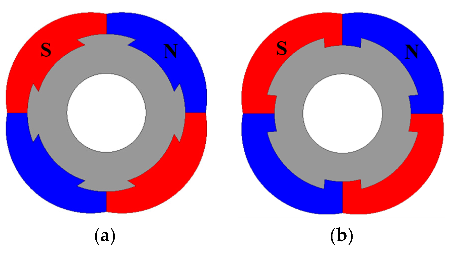
In this paper, the three different rotors (SPM, SIPM1, and SIPM2) have the same PM volume by adjusting h3. Based on the tradeoff between the output torque, torque ripple, the THD of EMF, and stress, the key parameters of SIPM1 and SIPM2 are listed in Table 3. The optimized SIPM1 and SIPM2 rotor structures are shown in Figure 6.

4. Performance Analysis and Comparison

In the previous section, the investigated motors are optimized by the FEA. In this section, the electromagnetic performances and mechanical strength of the SIPM motors are investigated and compared with the SPM motor.

4.1. No-Load Airgap Flux Density and Back-EMF

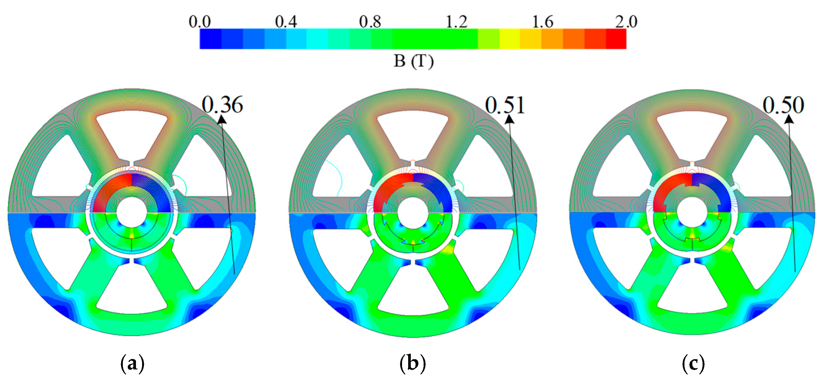
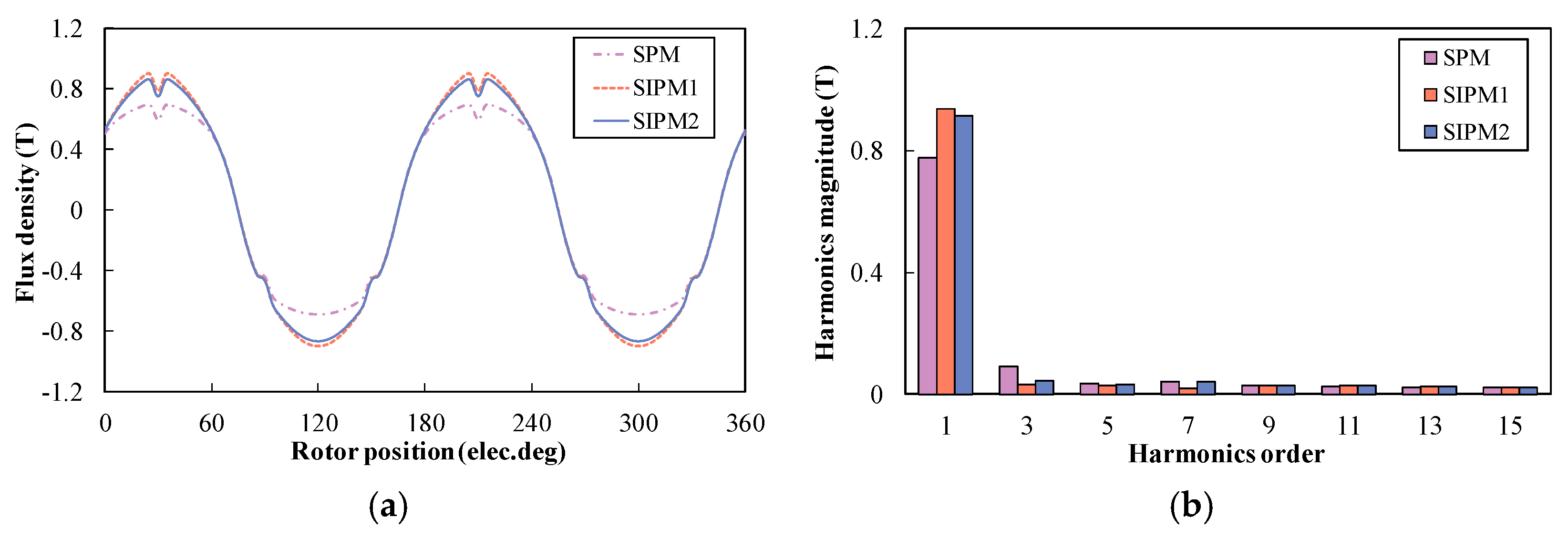
The no-load flux density distribution of these motors is shown in Figure 7. It can be seen that the flux density in the stator yoke of SIPM is larger than that of the SPM, which suggests that the SIPM can obtain larger PM flux-linkage. The no-load airgap flux density and harmonics order of the SPM and SIPM motors are shown in Figure 8. It can be seen that the SIPM1 motor has a slightly larger fundamental airgap flux density than the SIPM2 motor because it has a smaller rotor core volume to weaken the leakage flux effect. Meanwhile, it was found that the SIPM motors have higher fundamental airgap flux density than conventional SPM motors due to fact that the proposed SIPM motors eliminate the retaining sleeve, which reduces airgap resistance.
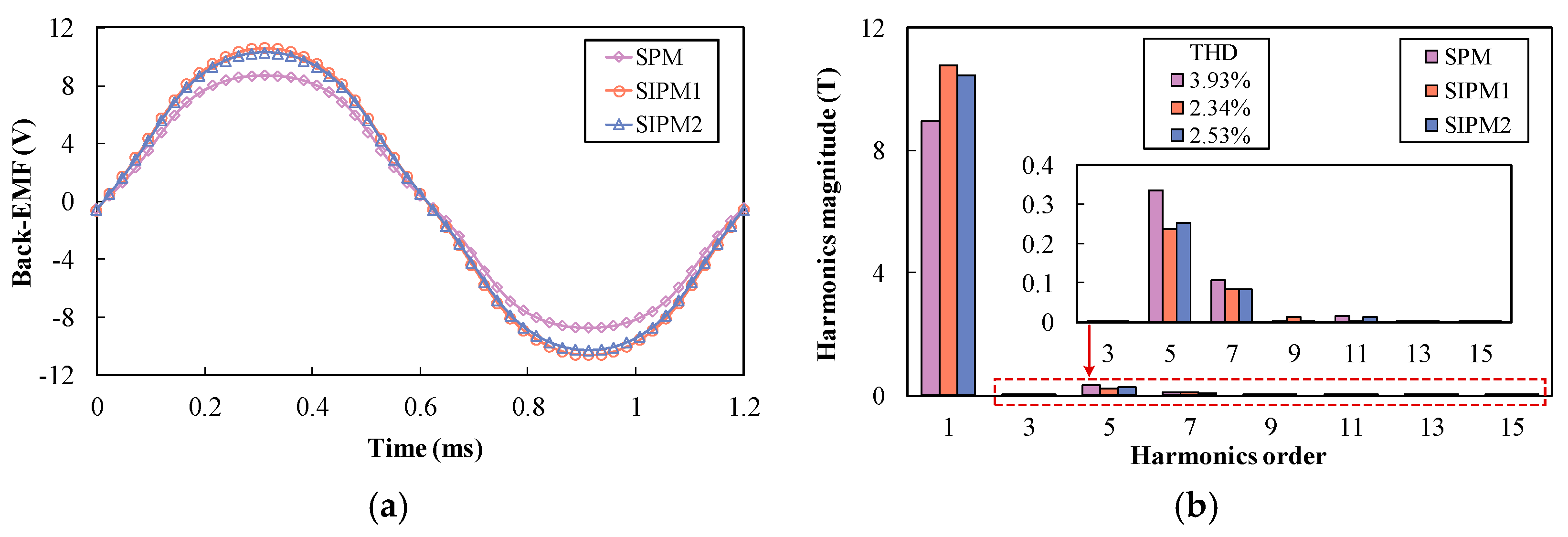
Figure 9 shows the no-load phase back-EMF and harmonics order of the SPM and SIPM motors at rated operating conditions. It can be seen that the amplitudes of these back-EMF agree well with the airgap flux density characteristics. Apparently, both SIPM1 and SIPM2 motors have a slightly lower harmonics order in fifth and seventh than the SPM motor, and they have lower THD due to the larger fundamental back-EMF.

4.2. Output Torque Characteristics

The cogging torque cycles per mechanical period, Nc, is defined as follows:
N c = L C M ( N s , 2 p )
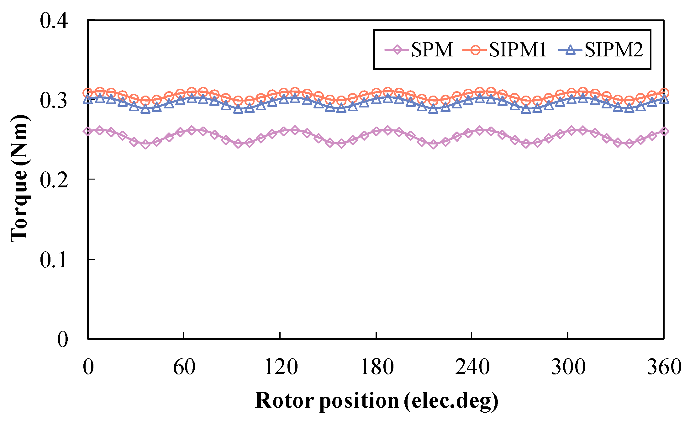
where LCM is the least common multiple, NS is the stator slot number, and p is the rotor pole-pair number. The period of cogging torque is the same due to the fact that the stator slot number and pole number have same LCM in these motors. As can be seen in Figure 10, three different motors have small amplitude of cogging torque, and the SIPM2 has the lowest value. Figure 11 shows the output torque of the SPM and SIPM motors under id = 0 control. The torque characteristics of these motors are displayed in Table 4. Where Tout is the output torque, ΔTpk-pk is the peak-to-peak value of output torque, Tc is the cogging torque, Tripple is the torque ripple, Vpm is the volume of the PM, and ηpm is the output torque per PM volume. As can be seen in Table 4, the presented SIPM1 motor has 1.22 times the output torque when the SPM motor is taken as the reference value. The SPM and SIPM1 motors have the largest and lowest torque ripple of the three motors, respectively. Meanwhile, the SIPM1 motor has the highest PM utilization ratio when PM usage remains the same.
Figure 12 shows the waveforms in these motors of the output torque versus phase current. From Figure 12, it can be seen that the SPM and two SIPM motors at the output torque varies almost linearly with the phase current over a wide range of phase currents. At the same time, the SIPM motors still achieves a higher output torque and PM utilization ratio than the conventional SPM motor.

4.3. Energy Loss and Efficiency

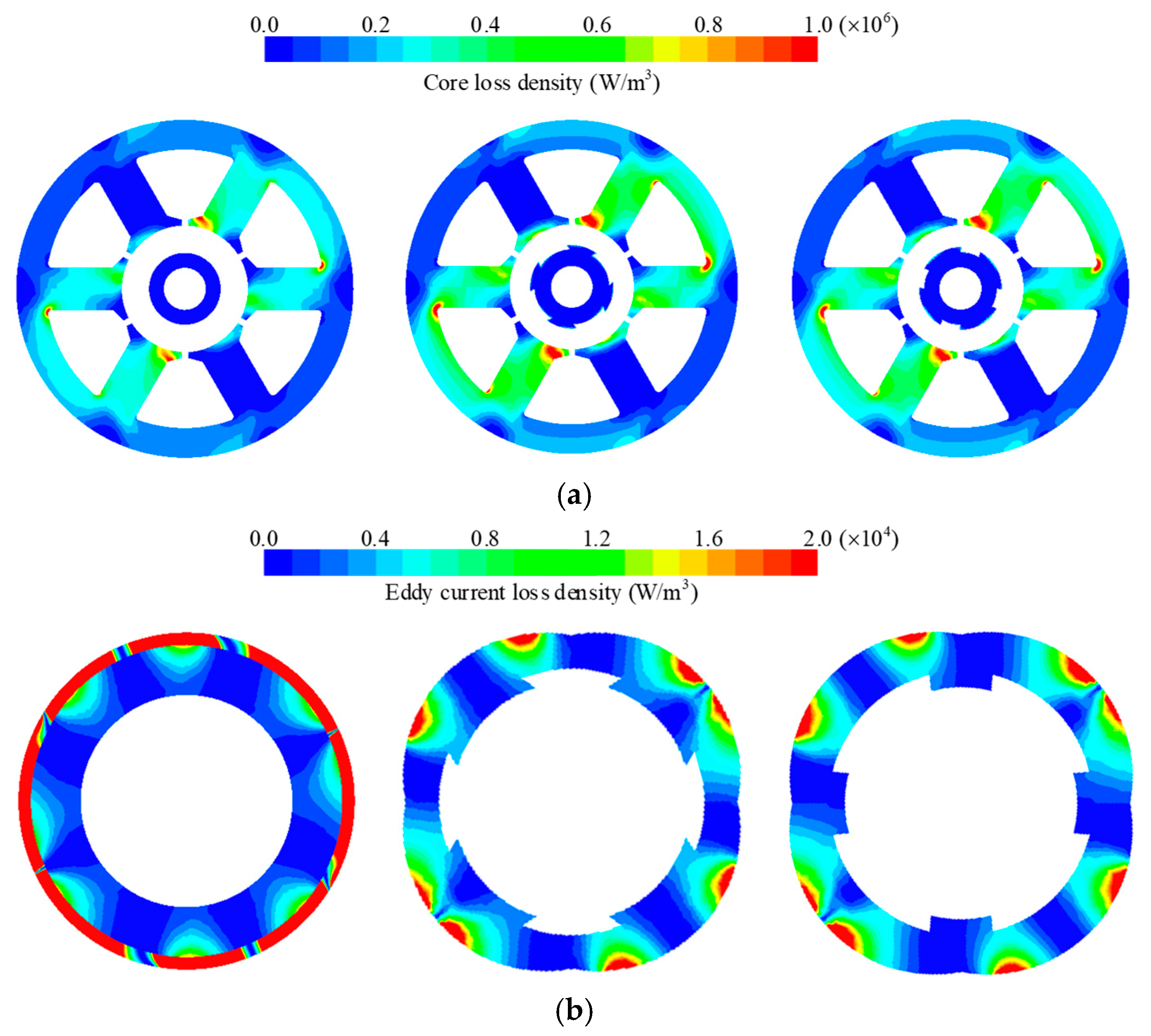
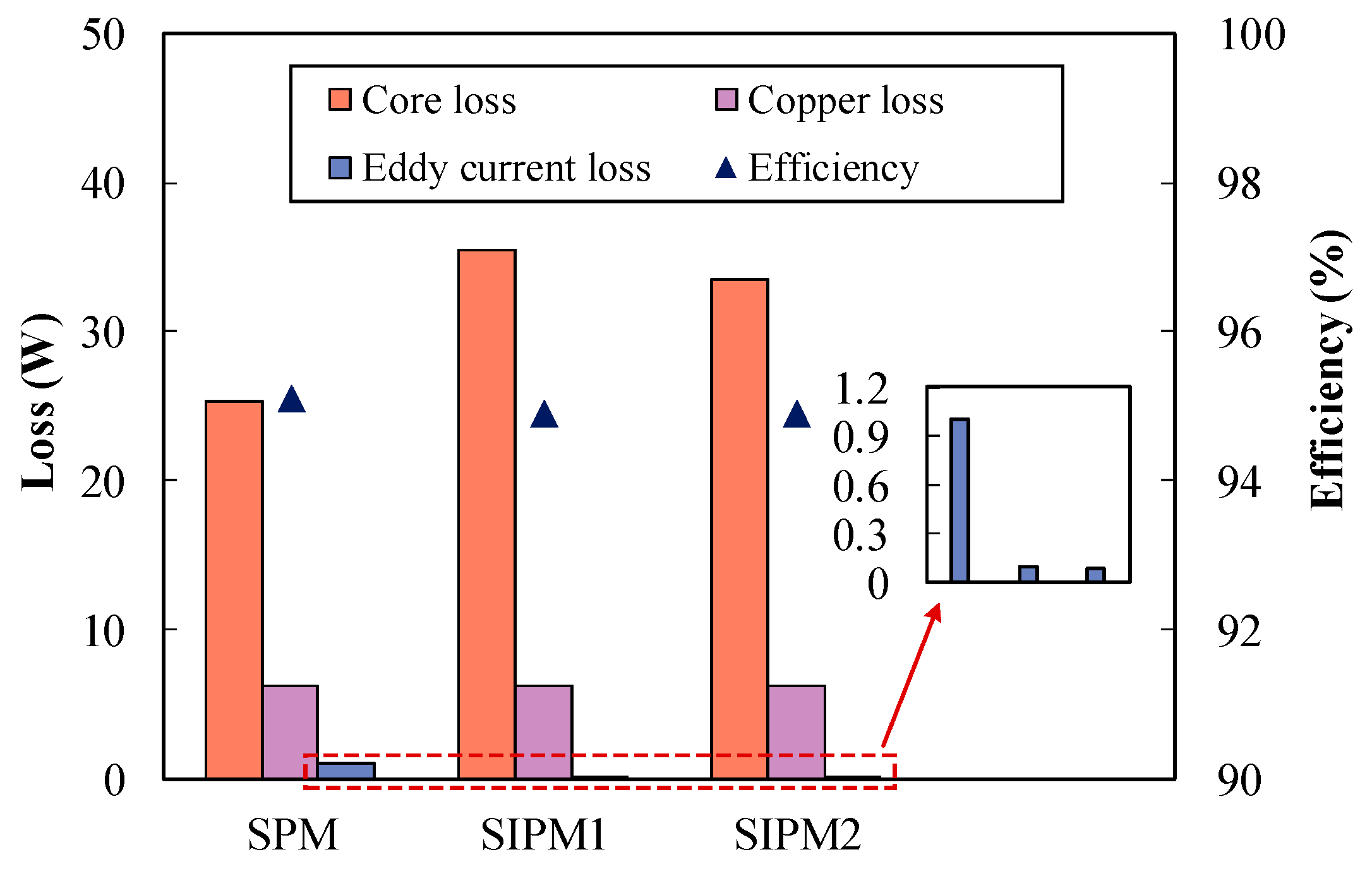
Conduction losses in the stator winding are typically the sum of two contributions: the dc loss and the ac loss. The total copper loss is calculated to be 6.3 W at the rated current. The distributions of loss density in the SPM and SIPM motors at rated operating conditions are shown in Figure 13. It can be observed that the SIPM motors have larger core loss density than the SPM motor due to the fact that they have a higher stator core flux density. Figure 13b shows eddy current loss between the sleeve and the PM. There is similar eddy current loss in the PM between the SIPM1 and SIPM2 motors. It is worth noting that the eddy current loss of the SPM motor is much higher than those of the SIPM motors, as shown in Figure 14. The main reason is that the armature field of the SPM motor has larger airgap resistance due to the existing stainless-steel sleeve.
The loss, including PM and sleeve eddy current loss, stator and rotor core loss, and copper loss, and the motor’s energy efficiency are shown in Figure 14. It can be seen that the SPM motor has less stator core loss than the SIPM motors, which results in higher efficiency than the SIPM motors due to slightly lower output power. Although the SIPM motors have larger loss than the conventional SPM motor, they can still acquire similar efficiency due to the improved output power.

4.4. Mechanical Strength

The rotor stress and deformation, as two significant mechanical factors, are analyzed and compared in the SIPM motors at the rated speed of 25,000 r/min. According to (3), thermal stress was simulated by increasing the rotor temperature to 80 °C. Meanwhile, the contact relationship of PM is set to frictional contact for simulating the PM glue failure state, and the friction factor is 0.15. The distribution of PM stress between the SIPM1 and SIPM2 motors, including radial, tangential, and equivalent, are shown in Figure 15 and Figure 16, respectively. It is shown that the radical stress of PM in the SIPM1 is 150.81 MPa, which is much higher than this in the SIPM2, about 34.46 MPa. However, there is slight difference in the PM’s tangential stress between the two configurations. The equivalent stress of the PM in the two configurations is the tensile stress. It is worth noting that the equivalent stress of the PM in the SIPM1 is 155.59 MPa, when the speed and temperature are 25,000 r/min and 80 °C, contrasting that of the ratio of the SIPM2, which is only 71.86 MPa. It can be seen that the equivalent stress of the PM in the SIPM1 motor has exceeded the maximum tensile stress, which is only 80 MPa, and the SIPM2motor is lower than the safe boundary.
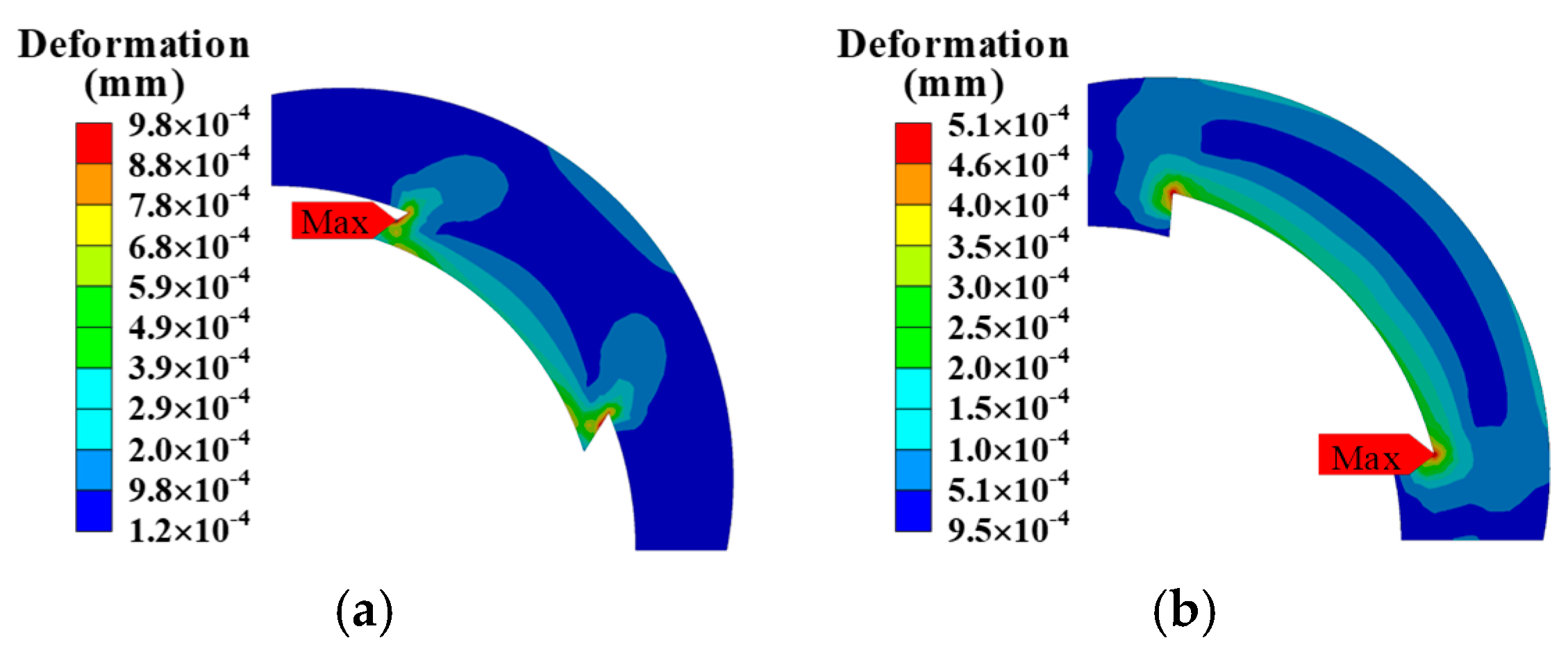
Figure 17 shows the PM deformation between the SIPM1 and SIPM2 motors; the position of maximum deformation is at the dovetail slot. It can be seen that the maximum deformation in the SIPM1 motor is obviously higher than that in the SIPM2 motor, and the difference between the two configurations is nearly double. This is due to the fact that the SIPM1 motor has higher equivalent stress than the SIPM2 motor at the dovetail slot.

5. Conclusions

In this paper, PM motors without retaining sleeves, which adopt novel motor rotor topology, are presented for HRSCPs. The performance of the SIPM motors is optimized by the established FE analysis method. Meanwhile, the electromagnetic and mechanical strength performance of the proposed SIPM motors is compared and analyzed with the conventional SPM motor. The detailed conclusions are as follows:
The proposed SIPM motors adopt the dovetail PM and rotor core to protect the PM with higher rotor strength without a retaining sleeve, and the risk of damage to the protective coating will be weakened. Meanwhile, it achieves up to 22% higher output torque than the SPM motor due to reduced airgap resistance. Meanwhile, the proposed PM structure is slightly more complex than the traditional tile-type structure. However, the manufacturing cost of the PM increase is limited, while the PMs volume remains the same among the three motors. The retaining sleeve is eliminated to simplify the process, and the cost of the whole motor is reduced.
By trimming the thickness of the PMs edge, the torque ripple of the proposed SIPM motors can be reduced compared to the SPM motor. Therefore, it has a single parameter optimization for the torque ripple.
Due to the eliminated retaining sleeve, SIPM motors have a lower eddy current loss than the SPM motor. However, the core loss of the SIPM motors is higher than the conventional SPM motor due to the fact that the stator core has higher flux density in the SIPM motors. In addition, the enhanced output torque leads to SIPM motors obtaining slightly lower energy efficiency, while the SIPM motors have higher total loss.
Finally, the SIPM2 motor has better mechanical performance when PM glue is not considered, including stress and deformation. The SIPM2 motor has a lower equivalent stress of the PM, which is lower than the maximum tensile stress, contrasting that of the ratio of the SIPM1, which has twice the maximum tensile stress.

Author Contributions

Investigation, K.M. and Y.L.; writing—original draft, K.M. and Y.L.; software, Z.W. and J.Y.; writing—review and editing, B.G. All authors have read and agreed to the published version of the manuscript.

Funding

This work was supported by National Natural Science Foundation of China under Award 52107051 and the Natural Science Foundation of Jiangsu Province under Award BK20210570.

Conflicts of Interest

The authors declare no conflict of interest.

References

  1. Luo, X.; Pan, L.; Yang, J. Mineral Resource Constraints for China’s Clean Energy Development under Carbon Peaking and Carbon Neutrality Targets: Quantitative Evaluation and Scenario Analysis. Energies 2022, 15, 7029. [Google Scholar] [CrossRef]
  2. Changmai, P.; Deka, S.; Kumar, S.; Babu, T.S.; Aljafari, B.; Nastasi, B. A Critical Review on the Estimation Techniques of the Solar PV Cell’s Unknown Parameters. Energies 2022, 15, 7212. [Google Scholar] [CrossRef]
  3. Wei, D.; He, H.; Cao, J. Hybrid electric vehicle electric motors for optimum energy efficiency: A computationally efficient design. Energy 2020, 203, 117779. [Google Scholar] [CrossRef]
  4. Li, Z.; Khajepour, A.; Song, J. A comprehensive review of the key technologies for pure electric vehicles. Energy 2020, 182, 824–839. [Google Scholar] [CrossRef]
  5. Beik, O.; Schofield, N. High-Voltage Hybrid Generator and Conversion System for Wind Turbine Applications. IEEE Trans. Ind. Electron. 2017, 65, 3220–3229. [Google Scholar] [CrossRef] [Green Version]
  6. Ismagilov, F.R.; Vavilov, V.E.; Miniyarov, A.H.; Urazbakhtin, R.R. Super high-speed electric motor with amorphous magnetic circuit for the hydrogen fuel cell air supply system. Int. J. Hydrogen Energy 2018, 43, 11180–11189. [Google Scholar] [CrossRef]
  7. Golovanov, D.; Gerada, D.; Sala, G.; Degano, M.; Trentin, A.; Connor, P.H.; Xu, Z.; La Rocca, A.; Galassini, A.; Tarisciotti, L.; et al. 4-MW Class High-Power-Density Generator for Future Hybrid-Electric Aircraft. IEEE Trans. Transp. Electrif. 2021, 7, 2952–2964. [Google Scholar] [CrossRef]
  8. Dadvar, M.; Afshari, E. Analysis of design parameters in anodic recirculation system based on ejector technology for PEM fuel cells: A new approach in designing. Int. J. Hydrogen Energy 2014, 39, 12061–12073. [Google Scholar] [CrossRef]
  9. Hong, Z.; Li, Q.; Han, Y.; Shang, W.; Zhu, Y.; Chen, W. An energy management strategy based on dynamic power factor for fuel cell/battery hybrid locomotive. Int. J. Hydrogen Energy 2018, 43, 3261–3272. [Google Scholar] [CrossRef]
  10. Shen, J.; Hao, H.; Yuan, C. FEA study on circumferential grooves on rotor retaining sleeve of high-speed pm brushless motors. Proc. Chin. Soc. Electr. Eng. 2012, 12, 53–60. [Google Scholar]
  11. Binder, A.; Schneider, T.; Klohr, M. Fixation of buried and surface mounted magnets in high-speed permanent magnet synchronous motors. In Proceedings of the Fourtieth IAS Annual Meeting. Conference Record of the 2005 Industry Applications Conference, Hong Kong, China, 2–6 October 2005; Volume 42, pp. 1031–1037. [Google Scholar] [CrossRef]
  12. Li, C.; Wang, K.; Liu, C. Torque Improvement and Cost Reduction of Permanent Magnet Motors With a Dovetailed Consequent-Pole Rotor. IEEE Trans. Energy Convers. 2018, 33, 1628–1640. [Google Scholar] [CrossRef]
  13. Rao, J.; Qu, R.; Ma, J.; Xu, W. Investigate the influence of magnetic bridge design on mechanical strength and electromagnetic characteristics in high speed IPM motors. In Proceedings of the 2014 17th International Conference on Electrical Machines and Systems (ICEMS), Hangzhou, China, 22–25 October 2014; pp. 22–27. [Google Scholar] [CrossRef]
  14. Arumugam, P.; Xu, Z.; La Rocca, A.; Vakil, G.; Dickinson, M.; Amankwah, E.; Hamiti, T.; Bozhko, S.; Gerada, C.; Pickering, S.J.; et al. High-Speed Solid Rotor Permanent Magnet Motors: Concept and Design. IEEE Trans. Transp. Electrif. 2016, 2, 391–400. [Google Scholar] [CrossRef]
  15. Liu, Y.; Ou, J.; Schiefer, M.; Breining, P.; Grilli, F.; Doppelbauer, M. Application of an Amorphous Core to an Ultra-High-Speed Sleeve-Free Interior Permanent-Magnet Rotor. IEEE Trans. Ind. Electron. 2018, 65, 8498–8509. [Google Scholar] [CrossRef]
  16. Jun, H.-W.; Lee, J.; Lee, H.-W.; Kim, W.-H. Study on the Optimal Rotor Retaining Sleeve Structure for the Reduction of Eddy-Current Loss in High-Speed SPMSM. IEEE Trans. Magn. 2015, 51, 1–4. [Google Scholar] [CrossRef]
  17. Zhao, W.; Lipo, T.A.; Kwon, B.-I. Optimal Design of a Novel Asymmetrical Rotor Structure to Obtain Torque and Efficiency Improvement in Surface Inset PM Motors. IEEE Trans. Magn. 2015, 51, 1–4. [Google Scholar] [CrossRef]
  18. Zubkov, Y.V.; Vereshagin, V.E. Designing of High Speed Permanent Magnet Electric Motors with Rotor Strength Verification. In Proceedings of the 2021 International Ural Conference on Electrical Power Engineering (UralCon), Magnitogorsk, Russia, 24–26 September 2021; pp. 414–418. [Google Scholar] [CrossRef]
  19. Wang, K.; Zhu, Z.Q.; Ombach, G. Torque Enhancement of Surface-Mounted Permanent Magnet Motor Using Third-Order Harmonic. IEEE Trans. Magn. 2014, 50, 104–113. [Google Scholar] [CrossRef]
  20. Du, Z.S.; Lipo, T.A. High Torque Density and Low Torque Ripple Shaped-Magnet Motors Using Sinusoidal Plus Third Harmonic Shaped Magnets. IEEE Trans. Ind. Appl. 2019, 55, 2601–2610. [Google Scholar] [CrossRef]
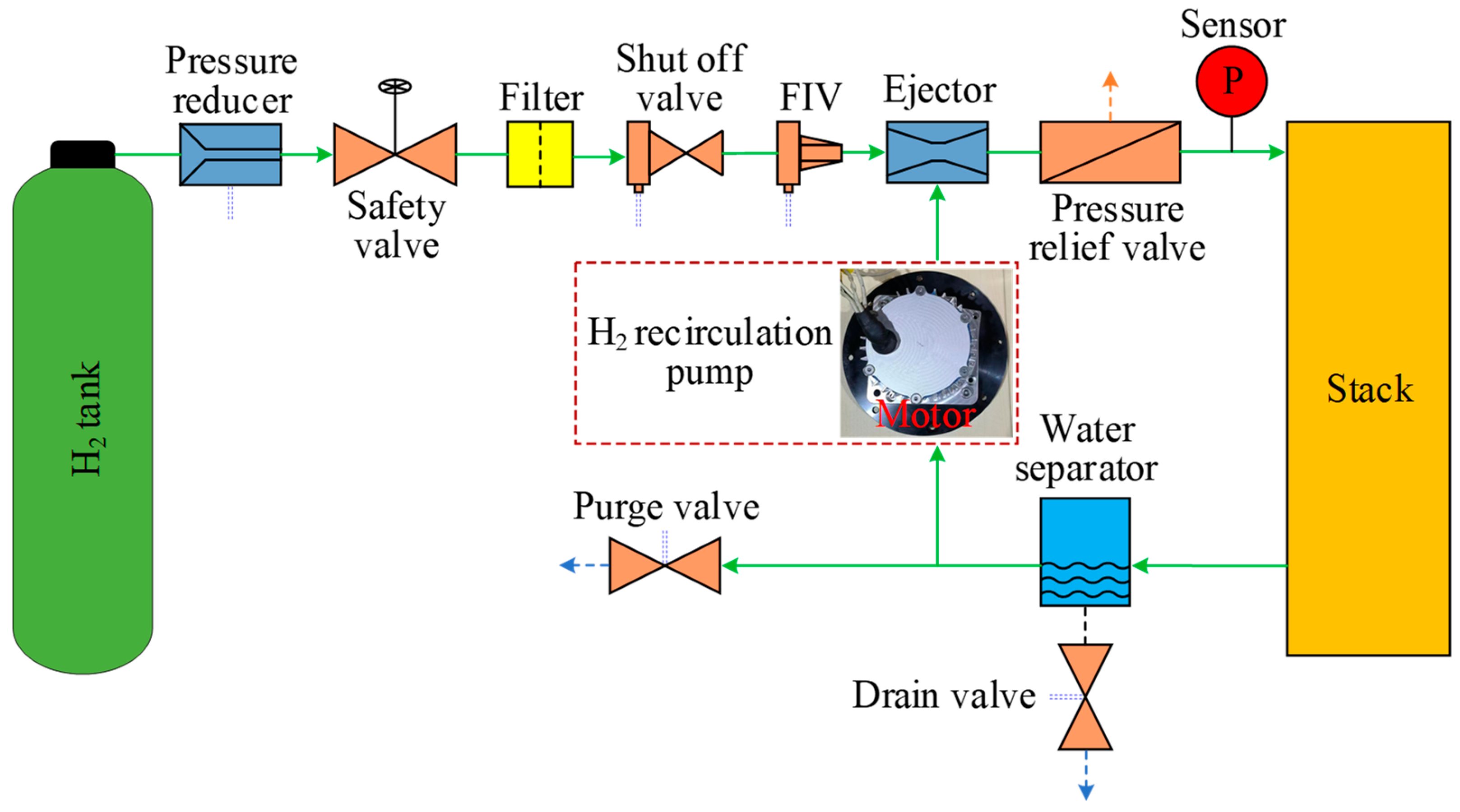
Figure 1. Hydrogen system.
Energies 15 08913 g001
Figure 2. Cross-sectional view of 6-slot/4-pole motor with different rotors. (a) 6-slot stator and windings. (b) Conventional SPM rotor. (c) SIPM1 rotor. (d) SIPM2 rotor.
Energies 15 08913 g002
Figure 3. Torque characteristics vs. h1.
Energies 15 08913 g003
Figure 4. Torque, torque ripple, and THD vs. h2 and θ1. (a) SIPM1. (b) SIPM2.
Energies 15 08913 g004
Figure 5. The tangential stress of PM. (a) SIPM1. (b) SIPM2.
Energies 15 08913 g005
Figure 6. Rotor structures. (a) SIPM1. (b) SIPM2.
Energies 15 08913 g006
Figure 7. No-load flux density distribution of SPM and SIPM motors. (a) SPM. (b) SIPM1. (c) SIPM2.
Energies 15 08913 g007
Figure 8. No-load airgap flux density. (a) Waveforms. (b) Harmonics order.
Energies 15 08913 g008
Figure 9. No-load EMF. (a) Waveforms. (b) Harmonics order.
Energies 15 08913 g009
Figure 10. Cogging torque.
Energies 15 08913 g010
Figure 11. Output torque.
Energies 15 08913 g011
Figure 12. Output torque versus phase current.
Energies 15 08913 g012
Figure 13. Distribution of loss density. (a) Core loss density. (b) Eddy current loss density.
Energies 15 08913 g013
Figure 14. Energy loss and efficiency.
Energies 15 08913 g014
Figure 15. Distribution of PM stress with SIPM1. (a) Radial stress. (b) Tangential stress. (c) Equivalent stress.
Energies 15 08913 g015
Figure 16. Distribution of PM stress with SIPM2. (a) Radial stress. (b) Tangential stress. (c) Equivalent stress.
Energies 15 08913 g016
Figure 17. PM deformation with SIPM. (a) SIPM1. (b) SIPM2.
Energies 15 08913 g017
Table 1. Main design parameters of 6-slot/4-pole motor.
ParameterSPMSIPM1SIPM2
Value
Number of slots6
Number of poles4
Stator outer diameter (mm)80
Stator inner diameter (mm)30
Air-gap length (mm)1.5
Rotor outer diameter (mm)28.5
Stack length (mm)30
Sleeve thickness (mm)10
PM thickness (mm)4-
DC Voltage (V)24
Rated phase current (Arms)35
Rated speed (r/min)25,000
Table 2. Material properties.
ParameterRotor CorePM
Density (kg/m3)76507650
Young’s modulus (GPa)210160
Poisson ratio0.270.24
CTE(μm/m/°C)1212
Tensile strength (MPa)45080
Table 3. Optimization results of key parameters for SIPM.
ParameterSIPM1SIPM2
Value
θ1 (°)5560
θ2 (°)4010
h1 (mm)1
h2 (mm)11.2
h3 (mm)0.50.9
Table 4. Torque characteristic of motors.
CharacteristicSPMSIPM1SIPM2
Tout (Nm)0.2540.3110.297
Tout (%)100122.4116.9
ΔTpk-pk (Nm)0.0170.0120.013
Tc (mNm)5.543.754.21
Tripple (%)6.73.84.4
Vpm (cm3)7.97.97.9
ηpm (Nm/cm3)0.0320.0390.038
Publisher’s Note: MDPI stays neutral with regard to jurisdictional claims in published maps and institutional affiliations.