Abstract
Compared with traditional injection tubular strings, the stresses on CO2 injection tubular strings are more complex. The results from field applications show that the phase transition of CO2 fluid in CO2 injection strings is an important factor in the calculation of temperature distribution and analysis of string mechanics. Therefore, we propose a strength analysis method for CO2 injection tubular strings that considers the CO2 phase transition. We selected four CO2 injection strings in an oil field in China as examples to evaluate their strength and safety. First, we established coupled differential equations for the temperature, pressure, and physical parameters of CO2 injection strings according to the theory of fluid flow and heat transfer. Then, we used an adaptive fuzzy neural network to construct the model for calculating the CO2 convection heat transfer coefficient and used this to obtain the high-precision convection heat transfer coefficients of tubular strings under conditions of CO2 flooding. We analyzed the injection-string deformations that resulted from the piston, spiral bending, expansion, friction and temperature effects according to the stress characteristics of the CO2 injection strings with packers under different working conditions. Finally, we performed mechanical analyses on the collapse resistance, internal pressure resistance, and tensile and triaxial stresses of the CO2 injection strings, and the results of these analyses provide a theoretical basis for the strength analysis of CO2 injection strings.
1. Introduction
The CO2 injection string is the most important transportation channel for fluid in a wellbore, and it determines the safety and effectiveness of the storage project. The strength–safety performance of the injection string is key to the success or failure of CO2 flooding storage [1]. However, during operation, the CO2 injection string is affected by the load that is imposed by the construction equipment, the fluid pressure inside and outside the string, the temperature change in the wellbore, and the CO2 phase transition in the string, in addition to other factors during operation [2]. When the loading conditions are poor and complex, accurate strength–safety assessment of the string becomes more difficult. Therefore, it is crucial to consider the characteristics of CO2 injection in analyses of variations in the temperature and pressure law with CO2 injection string along the well’s depth, the impacts of basic effects on the injection string, and the strength and safety of the CO2 injection string.
Due to the influence of temperature and pressure on formations, a large temperature gradient often appears in the tubular string along the well’s depth during CO2 injection, which leads to thermal stress in the tubular string. Therefore, the temperature field and thermal stress of the injection string are important factors in the evaluation of its safety. The traditional analysis method of the string temperature field is mainly used by researchers to establish differential equations of fluid heat transfer based on the theory of fluid heat and mass transfer, and they are solved on the premise that the structural parameters, thermophysical parameters, and initial and boundary conditions of the string are known [3,4]. However, the analysis method based on the traditional differential equation is complex, especially for fluid phase transition in a tubular string. Moreover, it is difficult to determine the fluid physical parameters, and the solution accuracy and prediction of the traditional flow-heat-transfer equation are not ideal [5,6]. In addition, in the usual mathematical model of string temperature distribution, scholars often specify the physical parameters of the fluid in the string as constants and ignore the nonlinear permutations of the CO2 physical parameters in the supercritical region. To overcome the shortcomings of the solution of the forward-heat-transfer problem, scholars in recent years have increasingly been attempting to build artificial neural networks based on experimental data to establish and solve the temperature–pressure coupling model of CO2 injection strings considering CO2 phase transition [7,8,9].
Within formations, the CO2 injection string is in a complex mechanical environment, and analysis and evaluation of its strength are complex and difficult. The mechanics of tubular strings during drilling were first explored by studies based outside China [10]. Later, with the deepening and refinement of research, the research field turned to injection tubular strings and the establishment of a mechanical model for the analysis of packer casing strings [11,12,13].
2. Analysis of Temperature–Pressure Coupling Mathematical Model for CO2 Injection Strings
We present the physical model of CO2 injection strings in Figure 1. CO2 fluid continuously flows into the well bottom from the injection string, and the formation heat and CO2 fluid undergo heat exchange, which affects the temperature and pressure-field distributions of the CO2 injection string. When the CO2 fluid reaches the well bottom, the temperature and pressure of the CO2 fluid exceed the critical values of their supercritical states, and the law of fluid heat transfer is difficult to predict.
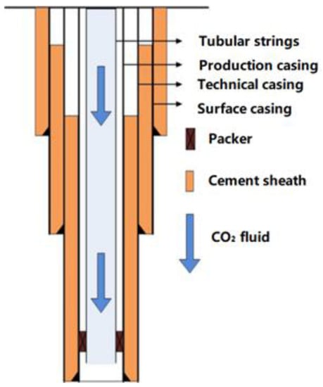
Figure 1.
Physical model of CO2 injection strings.
In order to establish a temperature-field model for CO2 injection strings, we made the following assumptions for heat transfer according to their characteristics: (1) CO2 fluid exists in the form of a segmented single-phase stable flow in the string; (2) there is steady-state heat transfer between the CO2 flooding injection string, and unsteady heat transfer between the string and the formation; (3) only the radial and axial heat transfer of the tubular string, and not the influence of heat source in the rock, is considered in the process of heat transfer.
During the process of CO2 injection, the fluid in the string exchanges heat with the annulus and formation, and the fluid energy changes during the flow process. According to the law of energy conservation, we can obtain the equation for energy conservation of CO2 fluid flowing in the microsegment as follows [14,15]:
The first part of the equation describes the heat transfer from the fluid to the cement sheath; the second part of the equation describes the heat transfer from the cement sheath to the infinite stratum. When the first part of the fluid transfers heat to the cement sheath, the expression of the radial heat change (dQ) on any microsegment of the injection string is as follows:
The total heat transfer coefficient of the CO2 injection string is the total thermal resistance generated by the CO2 fluid, string wall, oil casing annulus, casing wall, and cement sheath in the process of heat transfer from the formation to the injection fluid. Its value is related to the influence of the above factors on the heat flow resistance and convective heat transfer from the injection string to the casing. We selected the calculation formula of Ramey, Hasan, and others for the calculation, and the expression [16] is as follows:
The second part of the equation is the heat transfer from the outer edge of the cement sheath to the formation. According to the variation in the expression of the dimensionless heat transfer function with time, the heat change expression is as follows:
According to (Equations (1)–(4)), the heat transfer equation of the CO2 flowing downward in the tubular string is as follows:
The pressure gradient of the CO2 fluid in the tubular string is composed of the gravity gradient, acceleration, and friction. According to the momentum and mass conservation equations, we can obtain the expression for the pressure gradient of the fluid in the tubular string as follows:
According to the above derivation process, we can obtain the coupled equations for the CO2 fluid flow rate, density, pressure, and temperature as follows (Equation (7)):
In the temperature pressure coupling equation, physical parameters such as density are functions of temperature and pressure. The distribution of temperature and pressure along the well’s depth can be obtained by solving the fourth-order Runge Kutta equation iteratively.
In the process of flooding and injection, the CO2 fluid is continuously affected by changes in temperature, pressure, and velocity, which result in the transformation from liquid CO2 to supercritical CO2. As shown in Figure 2, the physical properties of supercritical CO2 have nonlinear change characteristics; thus, the change law of its physical parameters cannot be summarized using fixed value parameters or linear functions. When the formation exchanges heat energy with the CO2 fluid injected into the string, the mode of heat transfer is convective. The convective heat transfer coefficient can thus be used to characterize the rate of heat exchange of the CO2 fluid injected into the string by CO2 flooding.
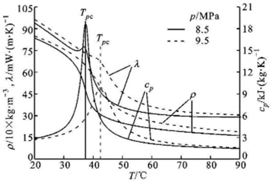
Figure 2.
CO2 physical parameters change with temperature and pressure.
The factors that affect the convective heat transfer coefficient of the fluid in the CO2 injection string include the fluid flow state (laminar or turbulent flow), the thermophysical parameters of the fluid (density, specific heat, and viscosity), the size of the string inner diameter, the influence of string bending, and the influence of the heat flow direction. These factors have complex effects on the convective heat transfer coefficient. In this study, we used an adaptive fuzzy neural network system (ANFIS) [17] to establish the model for the calculation of the convective heat transfer coefficient.
As shown in Figure 3, the first-order adaptive fuzzy neural network inference system is a fuzzy inference system with two inputs (X and Y) and an output (HF), which are associated with the fuzzification rule. The left input layer is the parameter input. In this study, the input layer selects the injection velocity (V), heat flow (qw), ground temperature gradient (K), and pressure (P) as the input parameters, and the output layer selects the Nusselt number (Nu) (dimensionless number) as the output parameter. After the training of the system model, we can obtain the required fuzzy rule base. MF1 and MF2 are marked with Gaussian distribution functions. The rule base of the model reflects the physical characteristics of the system, and the parameters of the membership function are shown in Table 1.
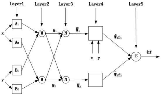
Figure 3.
First-order adaptive fuzzy neural network inference system.

Table 1.
Membership function parameters of Nusselt modeling.
After the system model training, the required fuzzy rule base will be obtained. The training model is based on four input parameters and the divided membership function. Through the initial parameter setting, the Nusselt number modeling knowledge base consisting of the following eight fuzzy rules will be obtained.
- (1)
- if(v is L)and(ρisM)and(C is S)and(k is S) then (Nu = a1,1*v + a1,2*ρ + a1,3*C + a1,4*k + a1,5)
- (2)
- if(v is L)and(ρisM)and(C is S)and(k is M)then (Nu = a2,1*v + a2,2*ρ + a2,3*C + a2,4*k + a2,5)
- (3)
- if(v is L)and(ρisM)and(C is M)and(k is L)then (Nu = a3,1*v + a3,2*ρ + a3,3*C + a3,4*k + a3,5)
- (4)
- if(v is L)and(ρisM)and(C is M)and(k is S)then (Nu = a4,1*v + a4,2*ρ + a4,3*C + a4,4*k + a4,5)
- (5)
- if(v is L)and(ρisL)and(C is L)and(k is M)then (Nu = a5,1*v + a5,2*ρ + a5,3*C + a5,4*k + a5,5)
- (6)
- if(v is L)and(ρisL)and(C is L)and(k is L)then (Nu = a6,1*v + a6,2*ρ + a6,3*C + a6,4*k + a6,5)
- (7)
- if(v is L)and(ρisL)and(C is S)and(k is S)then (Nu = a7,1*v + a7,2*ρ + a7,3*C + a7,4*k + a7,5)
- (8)
- if(v is L)and(ρisL)and(C is S)and(k is M)then (Nu = a8,1*v + a8,2*ρ + a8,3*C + a8,4*k + a8,5)
The structure of the fuzzy inference system can be adjusted by using neural adaptive learning technology similar to training neural networks through MATLAB fuzzy logic toolbox, and the best model training data are finally obtained, as shown in Table 2. Table 2 shows the best result parameters obtained by ANFIS after training the Nusselt number.
Table 2.
Subsequent parameters described by Nusselt modeling rules.
3. Stress Analysis of CO2 Injection String
The stress condition of the CO2 injection string in the well is relatively complex, and the main loads are the axial force (due to the self-weight of the tubular string), internal pressure (due to the CO2 fluid), external pressure (due to the annulus fluid), torque (due to spatial spiral bending), and bending moment (due to tubular strings bending). Therefore, in this study, we analyzed loads of the CO2 injection strings from the following aspects, in which the casing and injection strings are simplified: (1) the injection string is a homogeneous elastic rod with a constant linear thermal expansion coefficient; (2) the influence of the buoyancy force on the injection string, produced by the density change in the CO2 fluid after phase transition is ignored; (3) during CO2 injection, the formation, cement sheath, and casing are in a plane–strain state.
The internal and external pressures on the CO2 injection string include the hydraulic pressure on the string under annulus protection fluid and during CO2 injection, respectively. The change in the hydraulic pressure conforms to the change law of hydrostatic pressure, which only occurs with a change in the vertical well depth. According to the hydraulic pressure borne by the injection string, we can determine the hydraulic pressure outside the string at any well depth from the wellhead.
The external extrusion pressure borne by the CO2 injection string is produced by the liquid column pressure outside the string, which can be calculated as follows:
The main source of the internal pressure (Pi) of the CO2 injection string is the dynamic pressure of the injection fluid:
The axial force (FZ) caused by gravity at the depth (z) of the CO2 injection string is as follows:
The axial stress borne by the CO2 injection string includes the axial tensile and compressive stresses generated in the string, the additional axial bending stress caused by the bending of the string, and the shear stress caused by the injection string torque. In addition, the influence of thermal stress on the CO2 injection strings should be considered.
When the injection string under CO2 flooding is in a working state, the formation temperature and the convective heat transfer of CO2 fluid cause the injection string temperature to change, which is the temperature effect. The formula for calculating the axial stress caused by the change in the temperature of the injection string is as follows:
The injection string is subject to a bending moment due to buckling, the simplified calculation of which is as follows:
The bending moment (M(x)) between the tubular string and shaft wall after bending is generated and, in turn, generates additional bending stress:
The axial static stress caused by gravity at the depth (z) of the CO2 injection string is as follows:
The frictional force of the injected fluid flowing down the string wall causes the stress and axial deformations of the injected string to change. The axial stress generated by the friction resistance at the Z section of the injection string is as follows:
Therefore, the maximum axial stress of a section on the string is as follows:
When the injection string is subjected to internal and external pressures, the string wall is subjected to radial stress and circumferential stress, respectively (Figure 4).
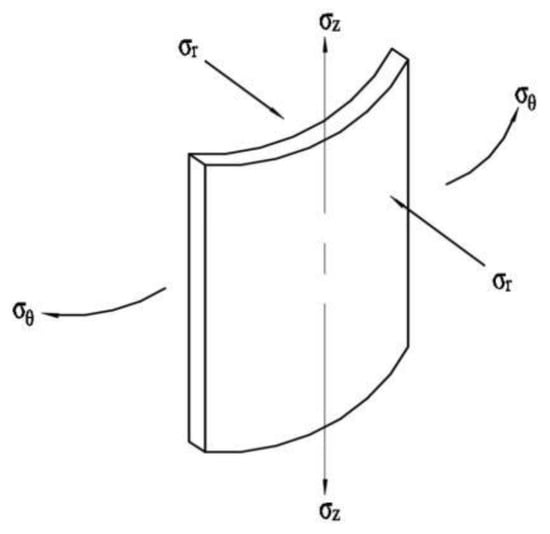
Figure 4.
Triaxial stress distribution diagram of CO2 injection string.
Therefore, we can determine the radial stress (Equation (17)) and circumferential stress Equation (18) in the string wall using the Lame formula [18]:
We can assess the strength and safety of the tubular string by the equivalent stress according to the fourth strength theory. According to the analysis, the inner wall of the injection string is a dangerous stress point at a dangerous section. The formula for the equivalent stress calculation is as follows:
Due to the influence of the CO2 fluid and annulus protection fluid on the internal and external pressure, temperature, and downhole tools of the CO2 injection string, the string produces deformation effects that are caused by different factors. Excessive axial deformation causes the packer to lose sealing or plastic failure of the string. Therefore, in order to carry out the stress analysis of a CO2 injection string, we need to analyze the causes affecting its axial deformation. The deformation effects of injection strings include the following: the Hooke effect, which causes axial tensile or compressive deformations due to the string self-weight; the piston effect resulting from different internal and external pressures on the injection string that cause axial deformation when the packer acts; the bulging effect, due to the different internal and external pressures on the injection string that cause radial deformation; the temperature effect, which affects the thermal expansion and cold contraction of the string due to uneven temperature distribution; the spiral bending effect, which occurs when the pressures at both ends of the injection string are greater than the unstable axial force. The deformations caused by the basic effects and total deformation are calculated as follows:
Deformation due to the Hooke effect:
Deformation due to the bulging effect:
Deformation due to the temperature effect:
Deformation due to the piston effect:
Deformation due to the spiral bending effect:
Deformation due to the liquid friction effect:
Total deformation under CO2 injection:
4. Example Analysis of CO2 Injection String
We evaluated the strength and safety of the CO2 injection strings in four wells in a certain block of the oil field using CO2 injection string mechanical analysis system software. We present the relevant calculation parameters in Table 3.
Table 3.
Basic parameters of CO2 injection strings in the oilfield.
We compared the calculation results for the temperature-field and pressure-field distributions of the CO2 injection strings in four wells in the same block of an oil field. MATLAB software was used to obtain the temperature–pressure distributions of the injection strings through the numerical calculation program and graph the distribution diagrams of the temperature and pressure fields (Figure 5).
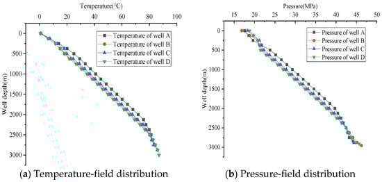
Figure 5.
Temperature and pressure distributions of CO2 injection strings.
According to the calculation results in Figure 5, the injection-string temperatures in the four wells continuously increase with the increase in well depth. The CO2 fluid injection temperature has a substantial impact on the temperature distribution 300 m near the ground of the tubular string. With the gradual deepening of the tubular string, the impact of the injection temperature gradually decreases. With the increase in the depth, heat is transferred from the formation to the fluid in the tubular string. At the same time, the pressure gradually increases with the increase in the depth of the tubular string, and its distribution law is approximately linear. As the CO2 fluid is in a supercritical state when it exceeds the critical temperature (31.1 °C) and pressure (7.38 MPa), the change in the density in this state is smaller than that under normal pressure; thus, the change in the pressure gradient caused by gravity is also smaller. At the same time, the viscosity of the supercritical CO2 is small; thus, there is less friction generated by the inner wall of the tubular string and the pressure gradient of the CO2 fluid in the supercritical section.
According to the temperature–pressure distribution results of the four injection strings in the oil field, we can intuitively obtain the CO2 phase transition process in the string. The depth of the tubular string and temperature of the CO2 fluid increase, and the CO2 fluid changes to a supercritical phase state (Figure 6). The enthalpy of the phase transition of the fluid in this process is 0; thus, the fluid injected into the string is in a segmented single-phase flow state, and there is no mixed-phase state in which the liquid and supercritical states exist at the same time.
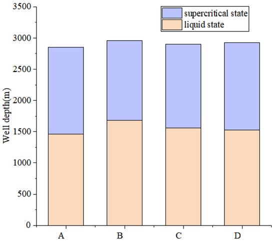
Figure 6.
Phase distribution diagram of CO2 fluid in four port injection strings.
Under complex field conditions, CO2 injection strings will elongate and contract. When evaluating the safety and reliability of an injection string, the worst conditions for string strength verification need to be considered. Using the above calculation procedures, we conducted analyzed and calculated the string deformation, load, and strength of the four wells in a specific block of an oil field. The results are shown in Table 4 and Table 5.
Table 4.
Deformation of tubular string during CO2 injection in four wells.
Table 5.
Tubular strings loads and strengths of four wells.
According to the comparison results in Figure 7, the thermal stress of the injection strings decreases at the CO2 supercritical section when considering the phase-state change in the CO2 fluid. Although the decrease in CO2 fluid viscosity due to the change in the CO2 phase state leads to reductions in the convective heat transfer coefficient and heat flow, the convective heat transfer coefficient in the injection string is much larger when there is a change in CO2 fluid phase state than there is no phase-state change. The final impact on the CO2 injection string is that the temperature difference and thermal stress in the injection string become smaller after considering the phase-state change.
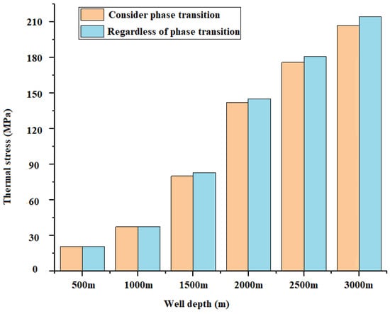
Figure 7.
Comparison diagram of thermal stress in two injection strings.
As can be seen from Table 4, in the process of CO2 injection, the influence of the friction effect on the deformation of the injection string is minimal. When the injection pressure of the CO2 is low, the temperature effect plays a major role. The injection string is mainly affected by the temperature and Hooke effects, followed by the bulging and friction effects.
It can be seen from Table 5 that the influence of the maximum axial stress on the string is greater than the equivalent stress. The values corresponding to the same parameters of the four wells are similar and the safety factor is greater than one, so it meets the safety production requirements.
5. Conclusions
In this study, we established a temperature–pressure coupling model of CO2 injection strings that takes CO2 phase transition into consideration. For the calculation of CO2 physical parameters, we used an adaptive fuzzy neural network to construct a model for calculating the convective heat transfer coefficient between the injection string and CO2 fluid. Based on the relevant theory of string mechanics, we evaluated the strength and safety of the CO2 injection strings in four wells of an oil field in China. Based on the results, conclude as follows:
- (1)
- The CO2 phase transition along the well’s depth occurred due to the coupled effect of temperature and pressure on the fluid in the injection string. In the same block, the four wells were at the same well depth and in the same working environment, and the critical position of the CO2 phase transition of the four wells was determined to be about 1500 m. Therefore, this prediction can be extended to the other injection strings in the block;
- (2)
- When the CO2 phase transition led to a substantial change in the convective heat transfer coefficient, this had a substantial impact on the thermal stress of the tubular string. Therefore, in CO2 injection strings, we cannot ignore the CO2 phase transition when calculating the temperature and pressure distributions and in the analysis of injection-string strength;
- (3)
- Finally, taking the CO2 injection strings of a domestic oil field as an example, the safety factors of the CO2 injection strings in a certain block of the oil field were found to be similar according to the calculation results of the fourth strength theory. Therefore, for the strength–safety analysis of injection strings with the same injection parameters in the same block, the strength and safety of other injection strings can be predicted using the calculation results from one well.
Author Contributions
Conceptualization, Y.Q. and Y.C.; Methodology, Y.Q., Y.C. and Y.D.; Software, Y.Q., W.L., J.C. and L.W.; Validation, Y.C., W.L. and L.W.; Formal analysis, Y.Q., Y.D. and L.W.; Investigation, Y.Q., W.L. and J.C.; Resources, Y.Q.; Data curation, Y.Q. and W.L.; Writing—original draft, Y.Q. and Y.C.; Writing—review & editing, Y.Q., Y.C., Y.D. and W.L.; Visualization, W.L. and J.C.; Supervision, Y.C. and Y.D.; Project administration, Y.Q. All authors have read and agreed to the published version of the manuscript.
Funding
This research was funded by [the National Natural Science Foundation of China (NSFC)] grant number [52274006 and 51974246].
Data Availability Statement
The data presented in this study are available upon request from the corresponding author.
Conflicts of Interest
The authors declare no conflict of interest.
Nomenclature
| ryo | Outside diameter of string (m) |
| Tso | Cement sheath-edge temperature, which is equal to formation temperature (°C) |
| Uto | Total heat transfer coefficient from fluid to cement sheath (W) (m·°C) |
| Tl | Temperature of fluid (°C) |
| Tso | Temperature of the outer edge of cement sheath (°C) |
| Tl0 | Injection temperature (°C) |
| Tn | Temperature at depth of n meters and radius (rn) (°C) |
| Tnso | Temperature of the outer edge of cement sheath at depth of n meters |
| A | Cross-section area in a tubular string (m2) |
| Cpc | Specific heat at constant pressure (J·kg−1·K−1) |
| g | Gravitational acceleration (m·s−2) |
| ν | Flow rate of CO2 (m/s) |
| I | Moment of inertia of cross-section of string to the neutral axis |
| E | Elastic modulus of string material |
| L | Setting depth of packer (m) |
| F(z) | Resultant force of live plug force on the string at well depth (z) (kN) |
| Fe | Equivalent axial pressure on injection string (kN) |
| μ | Poisson’s ratio of string |
| α | Linear thermal expansion coefficient of string (m/°C) |
| T(z) | Temperature of tubular string at well depth (z) (°C) |
| d | Inner diameter of injection string (m) |
| D | Outer diameter of injection string (m) |
| Pi | CO2 fluid pressure in a tubular string (MPa) |
| Po | Protective fluid pressure in the outer annulus of string (MPa) |
| Z | CO2 compression factor |
| Re | Fluid Reynolds number (dimensionless) |
| v | Molar volume of CO2 (v = ZRT/p) |
| rci, rto | Inner and outer diameters of the casing string, respectively (m) |
| hf | Convective heat transfer coefficient of CO2 flooding injection string (J/(s·m2·°C)) |
| hc, hr | Convective heat transfer coefficient and radiant heat transfer coefficient of annular space protection fluid, respectively (J/(s·m2·°C)) |
| kt, kc, kcem | Thermal conductivity of CO2 flooding injection string, casing string and cement sheath, respectively (J/(s·m2·°C)) |
| tD | Dimensionless time |
| η | Joule-Thomson coefficient |
| Greek letters | |
| ρm | Density of CO2 fluid (kg/m3) |
| ε | Internal energy of CO2 fluid per unit mass (m2/s2) |
| ω | Mass flow rate (kg/s) |
| ρ | Density of annular space protection fluid (kg/m3) |
| δ | Tubular string clearance (m) |
References
- Ma, W.; Qu, H.; Huang, W.; Dou, Y.; Wang, Z. Study on Failure Behavior of Gas Well Tubing Under CO2 Corrosion after Erosion. J. Fail. Anal. Prev. 2020, 20, 950–957. [Google Scholar] [CrossRef]
- Dou, L.; Li, G.; Shen, Z.; Wu, C.; Bi, G. Wellbore Temperature and Pressure Prediction Model and Its Affecting Factors for CO2 Injection Wells. Pet. Drill. Technol. 2013, 41, 76–81. [Google Scholar]
- Ramey, H.J. Wellbore Heat Transmission. J. Pet. Technol. 1962, 14, 427–435. [Google Scholar] [CrossRef]
- Alves, I.N. A Unified Model for Predicting Flowing Temperature Distribution. In Wellbores and Pipelines. SPE Prod. Eng. 1992, 7, 363–367. [Google Scholar] [CrossRef]
- Wu, X.; Wang, Q.; He, Y. Temperature-Pressure Field Coupling Calculation Model Considering Phase Behavior Change in CO2 Injection Well Borehole. J. China Univ. Pet. 2009, 33, 73–77. [Google Scholar]
- Guo, J.; Zeng, J.; Zhang, R.; Zhou, C. A Dual Transient Coupling Model for Wellbore of Carbon Dioxide Injection Well. Acta Pet. Sin. 2015, 36, 976–982. [Google Scholar] [CrossRef] [PubMed]
- Mehrabi, M.; Pesteei, S.M. Adeptive Neuro-Fuzzy Modeling of Convection Heat Transfer of Turbulent Supercritical Carbon Dioxide Flow in a Vertical Circular Tube. Int. Commun. Heat Mass Transf. 2010, 37, 1546–1550. [Google Scholar] [CrossRef]
- Scalabrin, G.; Piazza, L. Analysis of Forced Convection Heat Transfer to Supercritical Carbon Dioxide inside Tubes Using Neural Networks. Int. J. Heat Mass Transf. 2003, 46, 1139–1154. [Google Scholar] [CrossRef]
- Chen, J.; Wang, K.; Liang, M. Predictions of Heat Transfer Coeffcients of Supercritical Carbon Dioxide Using the Overlapped Type of Local Neural Network. Int. J. Heat Mass Transf. 2005, 48, 2483–2492. [Google Scholar] [CrossRef]
- Lubinski, A. Influence of Neutral Axial Stress on Yield and Collaspse of Pipe. AIME Trans. 1975, 97, 400–406. [Google Scholar]
- Li, Q.; Xie, G.; Zhang, J. Calculation Analysis of Initial Amount of Compression of Test String. Drill. Prod. Technol. 2001, 24, 48–51. [Google Scholar]
- Zhang, J.; Wu, X.; Long, X.; Liu, J.; Ren, B. Optimal Design and Strength Calculation and Check-up of Tubing String in Directional Hole. Nat. Gas Ind. 2005, 25, 67–70. [Google Scholar]
- Dou, Y.; Zhang, F. Mechanical Analysis of Well Testing Down-Hole String in Deep Well with HTHP and Its Application. Driling Prod. Technol. 2007, 30, 17–20. [Google Scholar]
- Zhang, J.; Yang, Z.; Zhang, Z. The Foundation and Application of Numerical Simulation of Fluid Flow and Heat Transfer Process; Chemical Industry Press: Beijing, China, 2009; pp. 13–36. [Google Scholar]
- Zheng, J.; Yan, X.; Dou, Y. Research on Failure Characteristics of Natural Gas Downhole Throttle. J. Fail. Anal. Prev. 2020, 20, 1155–1161. [Google Scholar] [CrossRef]
- Gupta, J.; Kujur, A.; Prasad, S.R.; Sharma, A.; Bhardwaj, A. Analysis of Frequent Failure of Oil Well Tubings Due to Formation of Longitudinal Slit. J. Fail. Anal. Prev. 2016, 16, 518–526. [Google Scholar] [CrossRef]
- Petukhov, B.S.; Polyakov, A.V. Boundaries of Regimes with Worsened/Heat Transfer for Supercritical Pressure of Coolant. High Temp. Mater. Process. 1974, 12, 221–224. [Google Scholar]
- Kuang, Y.; Li, B.; Liu, J.; Lu, H. Research on Buckling Behavior and Analysis of Sensitive Factors in Horizontal Well Drilling. J. Fail. Anal. Prev. 2016, 16, 376–383. [Google Scholar] [CrossRef]


Publisher’s Note: MDPI stays neutral with regard to jurisdictional claims in published maps and institutional affiliations. |
© 2022 by the authors. Licensee MDPI, Basel, Switzerland. This article is an open access article distributed under the terms and conditions of the Creative Commons Attribution (CC BY) license (https://creativecommons.org/licenses/by/4.0/).