Review

A Comprehensive Review of Conventional and Intelligence-Based Approaches for the Fault Diagnosis and Condition Monitoring of Induction Motors

by
Rahul R. Kumar
1,
Mauro Andriollo
2,
Giansalvo Cirrincione
3,
Maurizio Cirrincione
1,* and
Andrea Tortella
2
1
School of Information Technology, Engineering, Mathematics and Physics, University of the South Pacific, Private Mail Bag Laucala Campus, Suva, Fiji Islands
2
Electrical Machines Lab, University of Padova, 35121 Padova, Italy
3
Laboratory of Novel Technologies, University of Picardie Jules Verne, 80000 Amiens, France
*
Author to whom correspondence should be addressed.
Energies 2022, 15(23), 8938; https://doi.org/10.3390/en15238938
Submission received: 15 October 2022 / Revised: 18 November 2022 / Accepted: 20 November 2022 / Published: 25 November 2022

Abstract

:
This review paper looks briefly at conventional approaches and examines the intelligent means for fault diagnosis (FD) and condition monitoring (CM) of electrical drives in detail, especially the ones that are common in Industry 4.0. After giving an overview on fault statistics, standard methods for the FD and CM of rotating machines are first visited, and then its orientation towards intelligent approaches is discussed. Major diagnostic procedures are addressed in detail together with their advancements to date. In particular, the emphasis is given to motor current signature analysis (MCSA) and digital signal processing techniques (DSPTs) mostly used for feature engineering. Consequently, the statistical procedures and machine learning techniques (stemming from artificial intelligence—AI) are also visited to describe how FD is carried out in various systems. The effectiveness of the amalgamation of the model, signal, and data-based techniques for the FD and CM of inductions motors (IMs) is also highlighted in this review. It is worth mentioning that a variety of neural- and non-neural-based approaches are discussed concerning major faults in rotating machines. Finally, after a thorough survey of the diagnostic techniques based on specific faults for electrical drives, several open problems are identified and discussed. The paper concludes with important recommendations on where to divert the research focus considering the current advancements in the FD and CM of rotating machines.

1. Introduction

It is common that induction machines (IMs) are subjected to hostile environments and exposed to various sorts of undesirable conditions. These factors, when ignored, may result in the failure of IMs with serious repercussions on the industry, both economically and non-economically. Moreover, lives can also be lost if proper precautions are not taken. While most faults can be classed into electrical and mechanical faults, the underlying reasons that motivate the study of IM faults are as follows:
  • to obtain an idea on the evolution of the fault and predict their level of severity to ensure till when a regular operation of the motor is maintained;
  • to quantify the impact of the fault onto the motor behavior and interpret the signatures to understand the cause of failure (a posteriori). Thus, based on these factors, it is essential that FD and CM be carried out to ensure high reliability of the IMs and avoid losses to the industry in monetary and non-monetary terms.
The oldest method to deal with faults is maintenance after breakdown [1]. This is a significant disadvantage as it entails colossal downtime and is not acceptable, thus resulting in unexpected service interruptions and massive financial loss. Later on, the method of preventive maintenance was introduced, where maintenance tasks were carried out at planned regular intervals. However, this involved planned shutdowns and high maintenance costs. A few decades later, CM was slowly adopted by industries [2]. The CM has been recognized as the best modern practice for enhancing the reliability of machines, reducing maintenance costs, and increasing service availability. Under CM, continuous monitoring is carried out to detect faults in the system. This involves the observation of machine conditions, which arranges the maintenance tasks by using a data-driven approach. The data can be temperature, vibration, motor current, images, acoustic emission signals, shock pulses, etc.
This paper gives a comprehensive review on the fault diagnosis (FD) and condition monitoring (CM) of IMs. With regards to the databases accessed, journal articles, book chapters, as well as conference proceedings of the common engineering repositories were consulted (IEEE Xplore, Elsevier, Springer, Wiley, CRC, and more as per the references). In this review, up to 60% of the publications with respect to FD and CM were journal articles spanning over the last 2 decades, with the majority of publications considered in between 2010 and 2022. In addition, about 13% of the references in this paper contained books as well as book chapters, with the majority of publications produced in between 2005 and 2022. Up to 17% of the important conference proceedings were considered for this review paper, where most publications happened in the years 2010–2020. Selected review articles were also considered for this review paper and the majority of them were published in between 2013 to 2021. Utmost care was taken with regards to the searches made at respective databases and selecting the papers for review. This was to ensure that the major aspects of FD and CM were captured, starting from the background till advancements to date.
Following an extensive statistical study on rotating machinery faults, major faults associated with IMs are explored. The rest of the paper looks at the conventional and intelligent approaches used for the FD and CM of electrical drives. The standard methods for the FD and CM of rotating machines are visited first, and then its orientation towards intelligent approaches are discussed. Three main diagnostic procedures, model-based, signal-based, and data-based, are addressed and described in detail together with their recent advances. In particular, emphasis is given to motor current signature analysis (MCSA) and digital signal-processing techniques (DSPTs) mostly used for feature engineering.
Consequently, statistical procedures and machine learning techniques are also discussed to describe the FD process in various systems. The effectiveness of the amalgamation of the model, signal, and data-based techniques for the FD and CM of IMs is also highlighted in the literature survey. Finally, after a survey of the diagnostic techniques based on specific faults for IMs, several open problems are identified, and some recommendations are provided.

2. Rotating Machinery Fault Statistics

According to authors of [3,4,5], the number of working machines in the world was expected to be around 16.1 billion in 2011, with the rapid development of 50% in the preceding five years. Among these machines, the IMs are the most common ones and are widely used in the industry. They are involved in assuring continuity of the process and production chains of many industries. While the industry and application list for IMs is rather long, they are often used as critical components in nuclear applications such as nuclear plants, aerospace, and military-based applications where reliability is of utmost importance.
The IMs are indeed reliable in operations, yet they are liable to various sorts of undesirable faults. These deficiencies incorporate the following:
  • Rotor mechanical faults, e.g., bearing faults, eccentricity, bent shaft, and misalignment;
  • Stator faults, which can be recorded as a stator open phase, stator unbalance (because of short circuits), or expanded resistance connections;
  • Rotor electrical issues which include rotor open phase, rotor unbalance (because of short circuits), expanded resistance connections for wound rotor machines and broken bar(s) or a split-end ring design for squirrel-cage IMs, and rotor magnetic flaws such as demagnetization;
  • The failure of one or more power electronic components of the drive framework. IMs are symmetrical electric systems in view of the rotating magnetic field, so any sort of deficiency can change their symmetrical properties. Mainly all the electrical deficiencies that happen in the rotor impacts include a dissymmetry of the rotor circuits, both for the wounded IMs (dissymmetry of the windings impedances) and for the squirrel-cage IMs (broken bars or split-end ring designs).
Regarding the statistics available from surveys in [6,7,8], EPRI and Allianz databases are consulted for faults related to IMs, while IEEE working group considers the statistics of all the types of motors that are reported to have failed components, as shown in Table 1. Statistics in Table 1 show that majority of associated faults come from IMs. This is because it contributes to 80% of the failed components and also tops all the categories under the failed components. Interestingly, it can also be seen that the two largest categories of faults reported are bearing and winding faults which contribute to 44% and 26%, respectively, of the total number of motor failures. This is also comparable with the surveys included in [8,9,10,11,12,13,14,15,16,17,18,19] and the statistics from EPRI [7], with regards to bearing, as well as stator- and rotor-related faults (Table 2).
These studies also indicate that still there is a need for improvement with regards to CM because surveys have reported that most discoveries of failed component are found upon the usual maintenance routine. Considering faults in IMs, data from the IEEE workgroup described that 60.5% of the failures found during maintenance (scheduled) are from bearings, 8.3% are from windings, and 5.1% are from rotors. It is preferred that the least amount of faults are found during regular operation; however, bearing and windings (the two largest categories) represent 36.6% and 33.1%, respectively, of the failures discovered during the operation [6,20]. Hence, the major underlying causes of IM failures are inadequate and untimely maintenance. Correspondingly, mechanical breakage is said to be the largest failure initiator for IMs, whereas normal deterioration from age, high vibration, and inadequate lubrication are the significant contributors to IM failures.
Based on the above statistics, it must be noted that metrics presented here are not valid for all the scenarios. This is because the faults stated above are highly sensitive to the operating conditions of the machine and their occurrence may be because of different reasons [21]. With this aim, in the following sections, conventional and intelligent approaches for FD and CM are discussed.

3. Conventional Approaches for FD and CM

An all-important feature of FD and CM is that early-occurring faults can be detected and quick measures can be taken to avoid catastrophic outcomes. Even if the weak anomalies are observed, early-stage fault detection is essential for any type of platform that involves rotating machines. Regardless of the system in detail, a generic CM scheme would involve the following components:
  • A sensing task (primary variable);
  • A data acquisition task (digitizing analogue data for processing);
  • A data processing task (information identification);
  • A diagnostic task (reasoning and taking action from the processed data).
Based on different sensing approaches, diverse techniques were applied to perform the FD and CM of IMs. The most common standard approaches for analyzing faults in IMs are as follows.
  • Vibration analysis—To begin with, the primary sources of vibration in IMs are: (a) the response of the stator end windings to the emf generated on the conductors, (b) the dynamic behavior of rotor in the bearings as the IM rotates, (c) the response of the shaft bearing onto the support structure of the IM, and (d) the response of the stator core to the attractive force developed magnetically between the stator and the rotor [22]. Under this variety of occurrences, the mechanical component of the IM is immensely affected. Hence, through vibration analysis, the following faults can be identified: rotor eccentricity, unbalanced rotor faults, bearing faults, and gear-based faults. Under vibration analysis, the data essential for the identification are the oscillation force that is imparted by the IM, and it is directly proportional to the acceleration of vibration. Usually, piezo-electric sensors are deployed for fault detection in small motors, which work based on piezoelectric effect to generate electricity from mechanical stress. In addition, micro-electro-mechanical system (MEMS) accelerometers have also been used to acquire vibration data for fault detection and diagnosis in IMs [23], particularly for rotor bar faults. Through signal processing, vibration-based data are analyzed, and with the mathematical model of the IM, anomalies are detected. See survey for the FD and CM of rotating machinery using vibration analysis in [23,24,25,26,27].
  • Partial discharge analysis: This type of analysis is usually carried out to test the winding insulation in high-voltage systems. Small electrical discharge occurs as a result of insulation degradation; this is referred to as “partial discharge”. The parts in IMs which are mostly affected by the discharge activity are (a) the stator slot wall, where these phenomena can erode and affect the main wall insulation; (b) where coils emerge from the earth protection of the slot so that the insulation system is exposed to the surface discharge; (c) the end winding surface—at phase separation regions, whereby the surface is immensely affected, usually in the presence of dirt or moisture [22]. In general, the degraded winding insulation may have over 30 times the partial discharge activity than a normal one [28]. In a high-voltage machine, partial discharge analysis can identify the degradation before complete failure. This technique has been used extensively in high-power industries, and its reliability has been verified by [29]. A specialized piece of equipment, the partial discharge analyzer (PDA) is usually used to monitor the partial discharge in windings on an online basis [30]. Interesting studies related to PDA for stator winding insulation and recent advances in this area are highlighted in [31,32].
  • Induced voltage analysis: The fault can be identified by analyzing the induced voltage along the shaft of an IM. This induced voltage mainly occurs due to the degradation of the insulation winding (stator). A major drawback of this type approach is that very small to negligible voltage readings are given at the incipient stage of the insulation failure. The adequate amount of information in terms of voltage readings is given only when a significant amount of damage has already been inflicted upon the insulation windings [33]. Due to these reasons, this technique is not so common nowadays.
  • Torque analysis: Due to its symmetric construction, faults in the IM produce harmonics at particular frequencies in the air gap. Unfortunately, this air-gap torque cannot be measured directly and requires electrical quantities which are measurable (especially the motor terminal parameters). As an alternative to MCSA, authors of [34] have proposed load torque signature analysis (LTSA) in their work. On the other hand, reference [35] utilized the air-gap profile to discriminate faulty signatures from healthy where the torque normalization method has been used in conjunction with voltage and current measurements. The researchers have concluded that diagnosis entirely depends on the size and the rating of the IM investigated as the majority of studies [34,35] investigate the torque-speed characteristic curve to identify asymmetries in terms of stator- and rotor-related faults.
  • Acoustic analysis: This type of analysis entirely relies on the acoustic noise spectrum generated by the IM. Straightforward spectral analysis is carried out and compared with respect to the healthy signature for fault detection. Common faults analyzed using acoustic analysis are: bearing faults, air-gap eccentricity faults, and gearbox faults. In [36,37], some studies state that this type of analysis is instrumental for the early detection of the incipient faults, while some studies [38,39] utilize this approach for gearbox FD which is a recent trend. The major drawback of these techniques is that under a noisy environment, this approach may be impractical due to noise interaction from other sources (working machines, etc.) [35].
  • Chemical analysis: This analysis is one of the most effective but is an invasive technique used to monitor the health of IMs. In general, for IMs, the lubricants are subject to chemical analysis, mostly to determine the wear of the bearings. By taking the sample of the lubricant and performing X-Ray analysis, the deposits which chemically attack the bearings can be identified. This is because the lubricants usually not only carry products of their own but also contain the byproducts of the wear of the bearings and seals. With time and being subject to various environments (heat, cool, vibration, etc.), the quality of the lubricants can decrease, resulting in the degradation of bearings [20,22] due to presence of metal filling in the bearing (which rotate and damage the other ball bearings). In addition, the degradation of the insulation material in the IM can also chemically attack the parts which are vulnerable, such as winding insulation [22]. However, it should be noted that for this type of analysis, the detectability criteria are application-based, and tests are only feasible for large machines [40].
  • Thermal analysis: With this method, the detection of bearing and stator inter-turn faults is possible in IMs. Usually, the change in temperature of the IM reveals a lot of information on its performance by merely comparing the heat signature of the IM when it usually operates. The bearing fault via thermal analysis is detected because of the increase in the friction coefficient upon operation, which in turn increases the temperature of the IM. In terms of inter-turn faults, the temperature rises till the IM is affected. This can be visualized by means of thermal camera. While this type of fault can take time, thermal monitoring can reveal the cutoff regions to raise an alarm for the inter-turn fault. Most model-based studies have thermally modelled the IMs. They have been performed in two ways: (a) a lumped parameter thermal model and (b) a finite element analysis model [41]. Refs. [42,43] give an overview of recent thermal-based analysis for FD and CM in electrical machines.
  • Current analysis: With this technique, stator currents for the IMs are monitored. This is a non-invasive technique, whereby the stator current is measured by using Hall-effect current sensors. While a current transformer coil can be used, its readings are unreliable for low-frequency measurements. For analyses described in i–vii above, it is mandatory to deploy an additional sensor to acquire the parameters of interest. This requires additional work to be carried out when it comes to mounting the transducers. To some extent, this may affect the normal operation of the IM as well as being expensive when it comes to cost factor. On the other hand, acquiring stator currents without an extra device is feasible since the current transducers are already installed in the system which are responsible for the protection of the IM and its control mechanisms. In this regard, MCSA or current signature analysis (CSA) can be used as the sensor-less fault detection method which can be implemented without additional hardware. MCSA or CSA is achievable on an online basis, meaning current spectra can be acquired and analyzed while the IM is running. Most recent studies in the field of IM FD utilize MCSA or CSA as the base technique [3,5,17,44,45].
According to [20], MCSA or CSA comprise four important steps: (a) data acquisition, (b) data pre-processing/signal conditioning, (c) feature calculation, and (d) fault assessment.
  • Data acquisition: the three-phase stator currents of the IM are measured by means of current transducers, which are identical for all the phases. The acquisition is completed for both transient and steady states under various loading conditions.
  • Data pre-processing/signal conditioning: in this step, the digitized signal is further conditioned to remove noise components with filtering techniques. Thereafter, the signal is stored for further analysis including feature calculation.
  • Feature calculation: in the third step of MCSA/CSA, the calculation of the most notable features is made, which involves digital signal-processing techniques (DSPTs) [46]. Under the DSPTs, time-, frequency-, and time–frequency-based techniques are utilized. Based on the above DSPTs, the focus is on identifying and separating the constituents of the spectrum obtained upon data acquisition. Not only are the DSPTs utilized under this process, but also other state-of-the-art techniques such as neural networks, fuzzy and neuro-fuzzy, etc., are used in order to calculate the features. In a nutshell, MCSA/CSA is mostly used to identify the characteristic fault frequency component in the spectra, which may arise due to an anomaly in the investigated motor. It should be remarked that for each type of fault incurred, a unique fault frequency may spike up, indicating the nature of the fault. In some studies, the severity of the incurred fault from the frequency spectra can also be determined [47,48].
  • Fault assessment: in this step, after the detection of the fault, its severity and nature are determined by either the DSPTs [46] or pattern recognition techniques [49]. Usually, the severity factor and class of the fault are deduced by comparing them with the healthy stator current signature. Recent trends in the area of FD and CM involve artificial intelligence (AI)-based techniques mainly used for classifying and deducing fault severity, as per studies in [47,48].
In comparison with these techniques, CSA/MCSA is one of the most popular and economical solutions for the FD and CM of IMs. Indeed, in this case, the basic electrical quantities required for analysis can be readily measured using the existing protection circuit that are already installed. It is worth mentioning that MCSA is a non-intrusive approach, since the inexpensive current sensors (clamp-meters) can be conveniently deployed without disconnecting the electrical circuitry. In addition, with the rise in technological advancements, it is now possible to acquire the data remotely and perform the required analysis for the maintenance of IMs. In terms of safety, this type of approach requires no physical connection between the current sensor and the motor-driven equipment. Further benefits of MCSA are listed in [9,50,51,52,53,54].
In the framework of MCSA, Park’s vector current (PVC) [55,56] has received attention in recent decades to diagnose common faults in IMs. The three-phase currents can be transformed into direct and quadrature components ( i d , i q ) to reduce complexity and for better visualization. A common way to deduce the healthy state of the IM is to visualize the stator PVCs in the i d i q plane. A perfect circular pattern reveals the healthy condition of the IM, whereas an elliptical pattern denotes a fault. The more elliptical the graph, the more severe the level of fault [57,58,59]. This approach is usually adopted to detect the voltage unbalances, the stator-based faults, and single phasing operation of the IMs. A study in [60] also showed that the PVC approach is superior to Concordia transform in terms of FD in IMs.
Stating i a , i b ,   i c as the three-phase stator currents, the Park’s vector current components are given by:
i d = 2 3 i a 1 6 i b 1 6 i c
i q = 1 2 i b 1 2 i c
Refs. [59,61] have also utilized the PVC in detecting faults in voltage source inverters (VSIs) and additionally analyzed the deviation of the PVC pattern with respect to the healthy PVC pattern. Since IMs are highly symmetrical and offer any deviation, either in terms of fault or minor unbalance (that are always marginally present in IMs), the PVC alone cannot discriminate this failure/unbalance, as it ignores the non-idealities if no zero component is present and if supply unbalances for IMs are inherent. Further advances of the PVC by [56,62] lead to the “Extended Park’s Vector Approach” (EPVA, i P ), where the modulus of i d and i q ( i P which is the “extended” part of EPVA) is found as below:
i P = i d 2 + i q 2
The EPVA is applied to the steady-state diagnosis of stator inter-turn faults, broken rotor bar faults, unbalanced supply voltage, and mechanical misalignment. As mentioned by [56,62], this variation of the Park’s vector approach (PVA) gives more insight into the severity of the fault rather than identifying the type of fault incurred in the IMs.
Another common approach which comes under CSA/MCSA for the diagnosis of IMs is negative-sequence current analysis (NSCA) [63,64]. This technique has been widely used for detecting the stator inter-turn faults in IMs. Namely, the detection of asymmetries is analyzed by this approach and currents are converted from the unbalanced system to three balanced systems: positive-sequence, negative-sequence, and zero-sequence currents. The positive-sequence current has equal magnitudes with 120 ° of displacement giving a vector relationship of A B C . The negative-sequence current also has the same magnitude and phase displacement as the positive-sequence current; however, the phase rotation is inverted, i.e., C B A . As for the zero-sequence current, the magnitudes are equal but there is no phase displacement. From this analogy, the balanced system only has positive sequences. Hence, for detecting the asymmetries in IMs, the negative-sequence current is used. Usually, its magnitude is utilized to gauge the level of unbalanced effect incurred in IMs.
In terms of data for MCSA, the techniques stated previously utilize either the steady-state or transient currents of the investigated IM. Many other works have used the steady-state current signature in diagnosing faults in IMs [28,50,65,66,67]. Under the steady-state condition, a major disadvantage is that due to variations in speed or load, the current signature is immensely affected. In this case, the spectra become blurred, and conventional-frequency-analysis-based tools fail to work [68]. These limitations can be resolved by analyzing the three-phase current signature of the IM under the transient regime. This is because the current signal is less likely to be affected in case of no load or low loads. Since the starting current is 7–8 times higher than the steady-state current, even if a smaller IM is investigated, the variations in the current will be amplified under broken rotor bar fault [69]. Many approaches such as [40,70,71] have utilized the transient signals for the detection of faults in IMs.
While it is true that the conventional methods (i–viii) are used as the first approach for FD (mostly MCSA) in numerous industrial applications, various limitations still remain unaddressed. As such, these conventional techniques cannot be the only means of support for the development of diagnostic tools [3]. Under these circumstances, a systematic framework is required to further investigate the nature of failure in rotating machines and address them in a generic manner. Moreover, since MCSA has shown a large amount of potential, it can be used in conjunction with other methods to gain an in-depth analysis of various fault, which involves stator faults, rotor faults, and bearings for IMs. In the next sections, three main frameworks and their advances in FD and CM are discussed.

4. Fault Monitoring and Diagnosis Framework

While the foremost techniques applied for the diagnosis of rotating machines in industries were mostly invasive (these tests include AC high-potential tests, capacitance, core loss–loop, DC high-potential tests, dielectric absorption, grease analysis, growler, insulation resistance, partial discharge, polarization index, single-phase rotor tests—[20]), and FD and CM via non-invasive means became much popular towards the end of 20th century. The non-invasive techniques are mostly based on various mathematical approaches, which simply allow a diagnostic engineer to acquire data (current, vibration, temperature, or sound data) and analyze the condition of the IM without leaving the production line [72]. In a similar manner, this identification of faults enables one to develop a database that consists of healthy and faulty logs. Based on these data, intelligent systems (expert systems) can be designed to perform the FD and CM task autonomously.
As mentioned in earlier sections, MCSA is one of the most popular and accurate methods for IM FD and CM. It is completely non-invasive and involves analyses under steady and transient states. MCSA includes methods such as parametric analysis, non-parametric analysis, and high-resolution or sub-space-based methods. Under non-stationary conditions, high-order spectral analysis and statistical-based approaches are utilized [11,73]. Nowadays, MCSA is still used as the most important technique in conjunction with other topologies for IM FD and CM.
In this respect, there are three main families of diagnostic procedures, according to [17]. In all of these procedures, MCSA is employed at the initial step. The classification of these procedures on the basis of MCSA is given in Figure 1.
The following sub-sections give details on the model-based, signal-based, and data-based techniques for IM FD and CM.

4.1. Model-Based Approaches

The FD of IMs via model-based techniques requires prior knowledge of the system. A prior assumption on the initial conditions is also a requirement when representing the system in operation. The signals which are generated by the mathematical models assist in the detection and identification of the faults incurred in IMs. In addition, model-based techniques mostly rely on the accurate dynamic model of the system and are equipped to detect unanticipated faults. This is because model-based approaches take advantage of the “disturbances” or the so-called “residuals” [74], which are the differences between the outputs of the actual physical system and its corresponding mathematical model (Figure 2).
The residuals are usually indicative of a fault condition or sometimes signify certain levels of operation. Under different levels of operation, the model-based techniques (which is also classified as under analytical-based approaches) can be categorized into various groups which are listed in Section 4.1.1, Section 4.1.2, Section 4.1.3, Section 4.1.4 and Section 4.1.5.

4.1.1. Physical-Model-Based Approaches

Physical-model-based approaches rely entirely on the laws of physics to dynamically model a system together with some assumptions depending on its operation. Under this modelling technique, models are derived for each component. Using this component-oriented approach, the whole system can be described by compiling and inter-relating the equations for each component with others. As for IMs, dynamic modelling is a well-studied topic, and various models of the IM have been derived [75].
As a matter of fact, physical modelling was not intended for FD in the first place, since they did not contain the knowledge on how the system behaves in the presence of a fault. The dynamic modelling of systems was originally intended for control purposes, which required a mathematical interpretation of the system to be investigated. However, it is common knowledge that the detection of a fault in systems is possible since the response of a healthy system is different from the one in a faulty condition. In this respect, fault detection and fault localization are possible using only the physical model of the system. This is apparent since the physical model of the system is made up of various components; hence, any major deviation in terms of the outputs of the individual component directly points to the faulted part.
Moreover, apart from just physically modelling the system to detect and localize the fault, various other techniques over the years have been implemented to estimate the model parameters, not only in healthy conditions but also under faulty conditions. This has been a major shift in focus because of the rise in fault-tolerant-based control topologies [17,44]. Furthermore, the residuals represent an important piece of information, which forms the base of many estimation-based techniques. In parameter estimation-based approaches, the derivation of the dynamic model is the most important step for the technique to succeed and is advantageous for plenty of reasons such as accuracy, prediction of the next state, and identification purposes. These estimation-based approaches are covered in the next sub-sections.

4.1.2. State Estimation Techniques

Under analytical methods, a finite number of variables exist which are known as the state variables. Based on their inaccessibility due to cost of the sensor or large requirement of the measurements or their lack of physical meaning, these variables are not measurable. In most circumstances, they are usually estimated over time as the system evolves, provided that appropriate initial conditions are specified. Figure 3 below shows the principle of state estimation where the measured system input and output signals are fed to the observer. While the mathematical model of the system is already known, this type of approach plays a major role in reconstructing the state of the system on the basis of measurements and the existing model. Namely, Kalman filters and Luenberger observers have been the most effective and common methods utilized under this domain [76]. For example, in terms of FD and CM, the rotor currents (of a squirrel-cage IM) or the flux can be used on the basis of the Park’s model of the IM to gage an idea on certain types of faults, because the control algorithms utilize the estimations derived from the aforesaid techniques. While these techniques (Kalman filter and Luenberger observer) are based on linear representation around the model, operating points and improvements have been made by extending the existing linear-based observers. In this regard, the extended versions of these techniques are the “extended Kalman filter (EKF)” [77] and the “extended Luenberger observer (ELO)” [78], respectively. In addition, a recursive and straightforward formulation based on the Kalman filter has been used to detect stator inter-turn faults in IMs, as per [79]. Not only that, the aforesaid estimation-based techniques have been very useful in terms of FD in power converters, as per studies in [80,81].

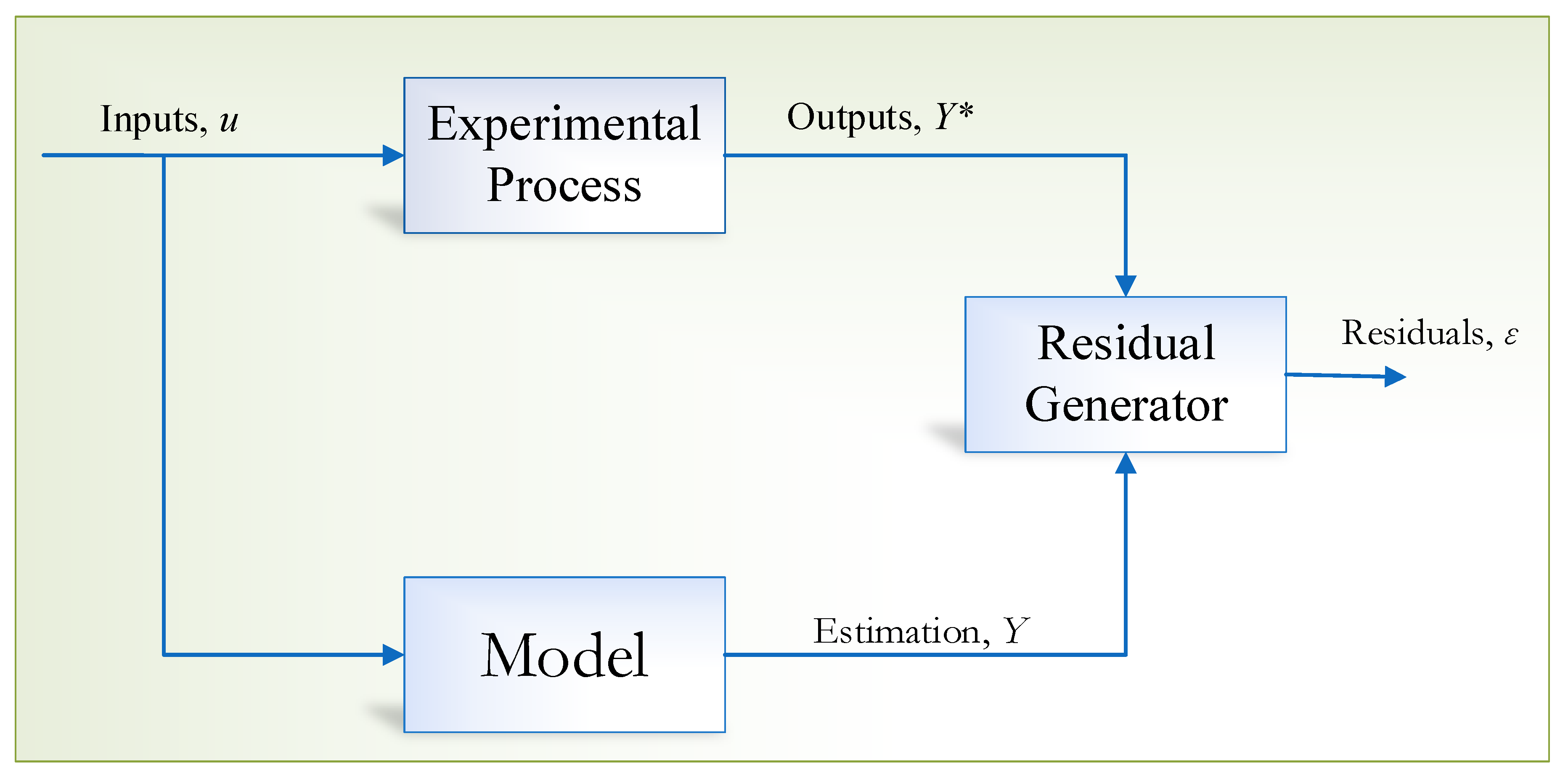
4.1.3. Residual Generation Techniques

The techniques associated with residual generation for the diagnosis of IMs involve both model and actual generated signals. Deviations between the model and the actual (experimental) signal are known as the residuals, and Figure 4 illustrates the principle of residual generation techniques. While different residual generation techniques work in their own way, the prime objective is to extract meaningful residuals such that a particular type of fault occurrence is accurately detected. For healthy conditions, the deviation between the model and experimental output would converge around zero. It is often the case that techniques related to residual generation offer an accurate diagnosis for actuators and sensors [82]; however, internal faults are detected much better by using identification techniques (Section 4.1.4).

4.1.4. Identification Techniques

Identification techniques rely completely on the experimental data together with the analytical model to determine the dynamic model of the system, which is to be monitored or perform FD on. Utilizing the input–output measurements, the identification techniques aim to continuously update the model parameters and converge to classify various operating conditions. In terms of the FD and CM of IMs, the fundamental idea is to estimate the parameters that characterize healthy and faulty conditions. A formalization of this principle is explained in detail in [83]. The estimations for the model parameters are guaranteed by the error minimization algorithms which are between the output of the model and the real physical machine (IM). A generic principle of identification techniques is demonstrated in Figure 5 below.
For the diagnosis of IMs, the electrical parameters which characterize them (faults) can be used as good-condition indicators. A common fault that has been diagnosed by parameter estimation techniques is the broken rotor bars. Under this fault occurrence, the rotor resistance can be monitored, and not only can the detection be modelled, but also its degradation using the identification techniques. In several studies, monitoring the rotor resistance is highly recommended since it directly provides information on the health of the rotor bar for a squirrel-cage IM. According to [45], the severity of the rotor bar damage is directly proportional to the rise in rotor resistance (measured by the parameter estimation techniques). In terms of monitoring the rotor resistance, the output-error estimation [84,85] non-linear high-gain observer [86,87] and the EKF [77,88] can be utilized.
A major drawback of monitoring the rotor resistance is the fact that temperature variations due to increased load can also result in rotor resistance variation. This drawback can be countered by introducing the internal machine temperature model within the model by means of other identification techniques and also acquiring prior data [89].
According to [89,90], it might be difficult for some faults by utilizing the above identification techniques. These faults include: an inter-turn short circuit, an inter-coil short circuit, static and dynamic eccentricity, and broken bar faults. This is because the main limitation of identification techniques is that persistent excitation is required to generate adequate data to be used by the algorithm. In the case of a controlled system operation (constant speed/excitation), these techniques may fail [91].
With this aim, these techniques require a dynamic system model in order to carry out the estimations for the model parameters. The model needs to be dynamic so that it is compliant with the techniques used. In doing so, sufficient knowledge of the system behavior under various operations is mandatory. In addition, not all faults can be diagnosed with the above parameter estimation methods (bearing/gearbox faults). As a result, diagnostic methods that require no model are highly recommended.

4.1.5. Finite Element Method

Apart from the dynamic modelling or optimized dynamical modelling (“optimized” here means the utilization of parameter estimation techniques for determining the accurate model parameter) of systems, the finite element method (FEM) is one of the most popular methods used to study the behavior of systems in many disciplines such as materials, fluid mechanics, electromagnetism, as well as thermal engineering. The FEM was introduced by Courant (1943) who investigated the field of “vibration of systems”. Further notable developments were made by Turner (1956) and Clough (1960), which led to a formal publication in a book by Strang and Fix (1973) [92]. To date, the FEM has been applied to vast areas and used extensively by the industry, mostly used for the purpose of system design [93].
The FEM derives from the ideology of the “divide and conquer” rule. In technical terms, for the analysis of complex systems or structures, the idea is to divide the system into small elements and characterize it on the basis of its geometrical/mechanical/electrical properties which are discrete, i.e., finite [94]. In this way, the elements can be studied very easily, considering its continuity. In terms of solving the finite element problem, the FEM calls for simultaneous solutions to the reaction problem of the elements due to the applied disturbances together with the interaction of the adjacent elements (connected with similar nodes). The solution is set up so that convergence is observed towards the behavior of the whole structure.
With FEM, it is possible to simulate many different scenarios to approximate the behavior of the systems in the event of fault appearance or its evolution. Due to its versatility, finite element analysis (FEA) offers in-depth information about the fault and has the potential to determine the way a system would behave in case of anomalies at various operating conditions. Using FEA, the condition of the system should be measured in the form of a variable value (state estimate) or extracted from a system signal in the form of a feature. Upon comparison, it is assumed that the state or feature investigated behaves similarly in both the FEA simulation and under experimental condition.
Due to their geometry, the IMs are complex to model and analyze for FD. In most cases, by using estimation-based methods, it is difficult to extract an accurate analytical or even a semi-analytical form for some characteristics, including faults. Although FEM is a form of approximation (for a system), it can return experimentally proven accurate results according to [95]. The diagnosis of IMs is based on its magnetic field distribution, which is allotted in different quantities for different parts of the IM. Some of the most influential factors that should be explicitly considered for the diagnosis of IMs via FEM are listed below:
  • the non-linearity of silicon steel materials;
  • the non-sinusoidal distribution of the windings and rotor bars;
  • accuracy in material modelling;
  • structural deformation.
While the FEM has several tremendous advantages, closed-form solutions, which can be used for the parametrized study of a device or structure, are not returned, which makes this approach a numerical model-based technique. The solution returned is, therefore, only a numerical approximation of a real solution. Once it is obtained, its validity is only for the configurations and parameters adjusted just before the simulation process. Since the calculations via FEM involve meshes, the FEM-based approach has an inherent error which is associated with the structure that has been modelled. For these problems, various approaches have been implemented, and the direction of research under this topic focuses more on optimization [96,97]. In the case of IMs, studies involving the diagnosis of stator- and rotor-based faults have been effectively carried out in [95].

4.2. Signal-Based Approach

Signal-based approaches do not necessarily require a specific model of the system. They only rely on the signatures given at the point of interest, mainly input and output terminals. All the analyses are carried out by a signal-type interpretation (comparison with the ideal case) or by an expert system (mainly pattern recognition techniques). For simplicity, the signal-based approaches are more common these days as they are simple to implement, and most of them are non-invasive. The analysis of faults for IMs under the signal-based approach is carried out under stationary and transitory states. In this respect, the following types of analyses are performed:
  • spectral analysis;
  • spectrogram;
  • temporal analysis;
  • via Wigner–Ville distribution [98].
The spectral analysis method mostly focuses on the stator, rotor, and bearing faults. They require accurate data which demand more computational effort. This category within the signal-based approach is also highly sensitive to the measurement quality and needs careful signal conditioning before analysis. While this approach is well suited for steady-state analysis, spectrogram and other categories of signal-based approaches are well suited for diagnosis under transient states [45].
Under temporal analysis, a comparison of the signal between healthy and faulty operations of the system is carried out to deduce the condition of the IMs [99,100]. A significant flaw under this type of analysis is that a direct comparison is impossible due to irregularities (phase shift and noise issues) associated with the measurements. While alleviating this problem is possible, the time complexity is intensely affected.
Another solution is to utilize time–frequency-based methods. These methods are based on Wigner–Ville analysis, which combines both the time and frequency analysis for monitoring the condition of the IM under stationary and transitory states.
In all of the above signal-based approaches for the diagnosis of IMs, studies in [3,9,11,12] reveal that MCSA is the most versatile way of determining the condition of IMs. This is because the starting current, steady-state current, transient-state current, or even shutdown current can usually be easily extracted and analyzed. Each of the currents mentioned above have their own advantages and disadvantages. In the next section, some recent advances in signal-based approaches are described with a specific focus on MCSA with DSPTs.

Advances in Signal Processing for FD of IM-MCSA

Over the past few decades, MCSA and motor vibration analysis (MVA) have always been the key approaches used for the FD and CM of IMs. There is flourishing literature on how these approaches have been adopted for the diagnosis of electrical drives [3,5,11,101]. In particular, there is an ever-increasing need for further studies with attention to the manufacturing sector.
MCSA analyzes the spectrum of the stator current and is useful for electrical machines working at a steady speed and rated load. Transient conditions are also essential in diagnostics, and these methodologies have been proposed for faults in this situation [102,103,104,105]. Apart from the current signature analysis, instantaneous power signature analysis and its variants have also received attention in the recent decade to detect both stator- [106] and rotor-based [107] faults. Through this technique, many fault harmonics are transferred into a well-bounded low-frequency band (0–100 Hz) [9]. Moreover, it gives a nearly linear response when measuring the severity of stator- and rotor-related faults [108]. However, a significant disadvantage of power signature analysis is the requirement of power analyzers [108,109]. In addition, even though the fault harmonics are bounded in a short range of frequency (as stated in [9,109]), the power spectra are heavily affected by noise due to unavoidable small anomalies, such as supply voltage asymmetry, electromagnetic interference, and possible load fluctuations with frequency bands overlapping with the faulted ones. Under these circumstances, it is difficult to identify the actual fault harmonics, and, consequently, additional countermeasures should be adopted [109], resulting in some information loss or degradation. According to the literature survey presented in [9], the stator current signature analysis still represents a more effective and reliable tool for IM fault detection.
Most FD schemes devised three decades back utilized the fast Fourier transform (FFT) as a base technique for the analysis of motor current or vibration signatures. The FFT has a few weaknesses, with regards to the masking of characteristic frequencies by supply frequency, the inexactness for transient signals, and so on. To address these weaknesses, diverse new techniques have been developed. In particular, digital signal processing (DSP) strategies have also been utilized in some MCSA-based methodologies.
Most of the faults in electrical machines may cause asymmetries in its electromagnetic field, thus adding characteristic fault frequencies to any underlying sensor signal. This can be investigated by frequency-domain analysis. Despite their adequacy, the traditional DSPTs have a few restrictions to be assessed for a correct FD.
Some of the current DSPTs are wavelet transform (WT), discrete wavelet transform (DWT), continuous wavelet transform (CWT), power spectral density (PSD), Wigner–Ville distribution (WVD), wavelet packet decomposition (WPD), short-time Fourier transform (STFT), Park transform, Prony, and fractal analysis [20,101]. The transient and the steady-state current in IMs have been utilized to diagnose broken rotor bar faults. Internal faults in IMs have been described using DWT and FEA. Motor signature analysis has been performed by employing PSD and WPD [9,12,20].
For the diagnosis of IMs, FFT performs well for steady-state analysis as it gives different frequency components that are present in the signal. In the event of motor data analysis, FFT transforms the time domain signal to the frequency domain, which requires an exact slip estimation for the frequency component in a spectrum. Likewise, if there is any occurrence of particular faults in the motor, frequencies produced are incredibly close to the fundamental component with small amplitude. Particularly for small motors under these circumstances, the diagnosis of the fault and the determination of the severity of motors under light load is no more reasonable [3,20].
Similarly, the variation of motor load, torque, inertia, supply voltage, or speed oscillation of motor can create harmonics which have similar characteristics to the frequencies associated with the faulty motors. Because of this, FD using motor current frequencies appears to be troublesome. A significant drawback of FFT analysis is that it cannot separate the harmonics because of motor faults arising from either load variation or fluctuation of voltage [9,20]. This problem was sorted out by utilizing the STFT strategy, which uses constant-sized windows to analyze all the frequencies (also the transient phase). A significant drawback of STFT is the matching of frequency content due to its limited window size. While it can be solved using a variable window size, WT carries this out suitably and is very appropriate for the analysis of the transient signal. WT decomposes a signal both in the time and frequency domains in terms of a wavelet, known as the “mother wavelet”. However, WT has a few disadvantages, e.g., the determination of a mother wavelet is very subjective, which may cause mistakes in the identification of parameters. A frequency response would be unsatisfactory since the low-order wavelet can overlap between bands. In order to address the issues imposed by WT, the Hilbert transform (HT) has been proposed. This strategy resolves the issue surrounding the inappropriate determination of the mother wavelet utilizing the envelope analysis of the signal. Moreover, the MCSA at the steady state has been investigated by this HT technique. However, variation or changes in the signal dynamics (non-stationarity in the dataflow) may affect the performance of the HT technique, and this is still an open problem [17,101].

5. Orientation towards Modern Techniques for FD

Ever since the rise in terms of the technological advancements, there has been a massive demand for techniques that can cope up with the overwhelming data-based systems. Towards the late 1900s, in the third industrial revolution, production lines and other processes were on the verge of automation. Under Industry 3.0, the memory programmable controls and computers were mounted within to obtain feedbacks to ensure safety and successful production loop. It is in this era where the conventional techniques alone were sufficient for FD and CM.
Not long after, the fourth industrial revolution came into effect which shifted the trend towards the advanced automation of the production systems. The already-existing computerized technology was further optimized and expanded to incorporate network connection which later led to “cyber-physical production systems” that yielded the smart factories (fully autonomous production system with minimal human intervention and interaction is complete via networks) to some extent [110]. A similar opinion is shared when it comes to the FD and CM of IMs since they have always been a part of Industry 1.0–Industry 4.0 [111,112]. Under these circumstances, it is essential to have a very efficient and reliable diagnostic system matching the latest trends due to changes brought about by Industry 4.0.
At present, conventional techniques (model-based or signal-based) are not sufficient to handle a data-driven industrial process, which also includes the diagnostic framework. This is because, in most circumstances, the amount of data is so enormous that its analysis requires a large amount of computational effort as well as field expertise to reduce some complexities associated within. Hence, it is necessary to adopt new modern techniques to solve the problems in which conventional techniques fail. This needs to be addressed under various frameworks. Hence, the focus is on the field of diagnostics, where the IM is considered to be the major component for investigation.
With regards to the above shift in the paradigm, data-based approaches are ever increasingly used specifically to monitor and supervise industrial processes. Applications of these sorts require field expertise and specialist knowledge in terms of data analysis and artificial intelligence (AI). The following section gives a basic survey of data-based approaches.

5.1. Data-Based Approach and Its Transition

For FD and CM, understanding or learning about various scenarios (healthy vs. faulty) is mandatory. The prediction of the future behavior of a system is connected with the historical experience and events. In this era of Industry 4.0, machine learning (ML) is suitable for the data-driven approach used for the FD and CM of the system with a specific focus on IM drives. The ML is part of the AI field, which is mostly concerned with the design and development of algorithms that enable computers to learn.
The prime objective of the ML research is to extract meaningful information from the data through the computational and statistical method and via supervised or unsupervised means, as well as to interpret it to the end-user in simple terms relating to the condition of the system with regards to FD and CM (Figure 6). With this aim, ML strategies are instrumental in describing relevant trends and characterizing the data so that statistical and probabilistic estimates are accurate.
Unlike conventional ones, data-driven approaches rely entirely on the data provided. They are capable enough to intelligently detect and identify the correlated trends in the system dynamics so that the estimation on the current and the next state in terms of health can be accurately predicted. Under the FD and CM of IMs, the data-driven approach, in conjunction with ML techniques, follows a systematic approach that incorporates the following:
  • statistical and probability theory;
  • data pre-processing;
  • feature engineering;
  • dimensionality reduction;
  • classification (supervised or unsupervised).
For this purpose, the data-driven approaches are divided into two classes: (a) statistical approaches and (b) ML approaches. While the former approach forms the backbone of the data-driven approaches, the latter is more popular and has been a hot topic ever since the last few decades. Table 3 and Table 4 illustrate the classification of statistical and ML approaches, respectively.

5.2. Data-Driven ML-Based Approach

Considering the literature with regards to diagnostics, researchers have highlighted that statistical approaches (Table 3) can form the base of AI techniques or ML-based approaches (Table 4). ML approaches improve AI techniques within the statistical-based framework. Hence, it is apparent that some element of statistical calculation should be employed when applying ML techniques on data. ML techniques are strongly related to classification problems (or clustering), which enables the identification of faults in electrical drives. Based on the data provided, the classification can be divided into two parts:
  • Supervised classification: under this class, the input data and its corresponding labels are provided. In this way, the algorithm can learn the patterns, so as to isolate the healthy and faulty conditions of electrical drives. The raw data acquired from sensors are subject to signal conditioning and feature calculation, which results in the creation of successful classifiers after adequate training for real-time diagnosis.
  • Unsupervised classification: under this class, the data have no predefined class label. In this procedure, the algorithm can automatically organize the data after some parameter tuning and finally assign clusters to each group with similar patterns. Under this scheme, various clustering algorithms can be used.
Recent studies show that semi-supervised frameworks can also be developed to further optimize classification and detection capability [49]. These types of classification can be further divided into two categories: (a) the discriminative approach and (b) the generative approach. These two categories rely on the estimation of the posterior probability, which plays a significant role in the field of diagnostics, especially to acquire information on the likelihood of the occurrence of a fault.
The discriminative approach enables the learning of a single model that predicts the class in the form of a binary relationship. This means that the assigned class, regardless of its location (assuming it is very near to the decision boundary), has a 100% a posteriori probability for the selected class and a 0% probability for the other. In this way, the data mapping depends on the discriminative function without considering the class membership probability of the data.
The generative approach models the prior probability of each class and then chooses the best fit for the observed data (based on optimization methods such as MLE, least-square estimation, Monte Carlo, Markov chains, etc.). Thereafter, by employing Bayes’ rule, the generative approach produces a different probability density model for each class and yields the overall probabilities for each variable. Hence, under each observation, the class probabilities are assigned to quantify the likelihood of the class, giving an idea on the position of the observation and its closeness to the decision boundary. See Table 4 for common ML-based approaches.

6. The Amalgamation of Model, Signal, and Data-Based Techniques for the Diagnosis of IMs

Based on the above discussions, each of these diagnostic frameworks have pros and cons as highlighted in [3,68]. Inspired by the idea of ensemble methods and majority rule classification topologies, the drawbacks of each diagnostic approach can be alleviated by creating a hybrid type of system where the model, the signal, or the data-based schemes are combined in a single architecture.
Although this approach may be cumbersome and may require additional hardware or software, it gives very good results in terms of efficiency and accuracy. In general, model-based techniques are combined with AI-based approaches for the optimization and parameter estimation of electrical drives. In particular, signal-based approaches have been applied for the diagnosis of IMs, either alone or in conjunction with model-based approaches. In this application, conditioning of the residuals or other associated signals is essential. While it is apparent that signal-based approaches cannot handle a huge amount of data, there is currently a trend to combine DSPTs with AI-techniques for the design of FD and CM schemes.
Over the last few years, there have been advances in research in devising new CM schemes for electrical machines and drives. In particular, numerous approaches [11,12,20,44] have been developed to address the problem of non-linearity and other associated factors related to IMs. The trends and advances in the FD and CM areas mostly focus on the application of AI [3,9,12,17,44], which gives a clear indication that AI techniques, along with motor circuit analysis (MCA), MCSA, or MVA, play a significant role in electric motor diagnostic systems with resulting higher practicability, reliability, and automation. In addition to DSPTs for the FD of IMs, novel AI-based algorithms for fault detection, classification, and diagnosis purposes have been produced throughout the years. Many recent works have highlighted the utilization of AI tools where feature engineering is achieved through cutting-edge DSPTs and other novel topologies and new neural-based techniques for classification [3,11,114].
Figure 7 summarizes a system architecture for the diagnosis of any system using a data-based approach. This generic architecture includes all possible frameworks that can be designed with the previous three diagnostic approaches. It should be remarked that in the FD and CM of electrical drives, the MCSA plays a crucial role and should always be used to ensure proper fault detection and isolation. Moreover, even if the feature engineering and dimensionality reduction block-sets require domain expertise, pre-processing with MCSA can now be easily applied within deep learning frameworks; indeed, it can extract noteworthy features as well as reduce the dimension in a single architecture. Most studies in deep learning approaches involve semi-supervised networks and “transfer learning” [115] to enhance the overall system accuracy without the need of feature engineering or signal conditioning. In order to explain these kinds of models, it is possible to “probe” [116] its network (decision making layers) and visualize the feature maps to discover important condition indicators (feature) that may be instrumental for FD. Though these strategies are currently in their infancy stages due to non-stationarities in the data, the prior processing of signals remains necessary.

7. Intelligent Approaches for FD

7.1. Overview of Intelligent Architectures in FD

The development of AI-based FD and CM strategies for IMs mostly rely on data-driven models these days. A generic procedure to establish an AI-based FD and CM scheme is based primarily on the acquisition of relevant data from the hardware (the IM in this case). This is followed by the extraction of important features with the help of MCSA, MCA, or MVA through DSPTs. Thereafter, the most significant features are selected in accordance with dimensionality reduction, as well as other feature extraction techniques. Finally, the extracted features are used to develop a classifier for the fault identification and evaluation of the fault severity. In further sections, recent advances in the FD and CM of IMs are discussed, following the diagnostic scheme described in Figure 7. Intelligent AI-based diagnostic frameworks are particularly considered.

7.1.1. Recent Advances in FD for IMs via Intelligent Techniques

In the recent decade, there has been a flourishing amount of literature that involves the development of the diagnostic schemes for electrical machines and drives to overcome the shortcomings of conventional methods. The main composition of intelligent FD and CM framework relies on the following aspects:
  • Feature engineering—derives appropriate condition indicators of the machine in question and correlate the changes with respect to the healthy conditions of the motor. This can be achieved by employing DSPTs and other conventional methods, and requires domain expertise. Studies show that it is possible to use deep learning, especially that implemented with convolutional neural networks (CNNs), to combine the feature engineering and feature extraction parts [38,117]; however, extensive data and fine-tuning are required to achieve better results. While it may be cumbersome to try out various new architectures for the diagnosis of IMs involving CNNs, deep learning is still a promising approach and should be explored more in detail.
  • Feature extraction and dimensionality reduction—since feature extraction methods and the dimensionality reduction (DR) are complementary, both of them can be exploited under the diagnostic framework. The term feature extraction means extracting significant or noteworthy features from the previous feature engineering step. The method of extraction may vary and would involve specific feature ranking techniques to demonstrate the variability of each engineered feature. On the other hand, the term DR refers to a reduction in the feature set (FS). The DR is an essential step in ML, since the resulting FS reduction simplifies the classification and reduces the training time and other time complexities. Unlike other ranking-based feature extraction techniques, which tend to reduce the importance of the bottom-ranked features, the DR can reduce the dimensionality of the FS while preserving the contribution of all the features. Various studies in relation to the topology or geometry-preserving DR techniques have been explored by researchers in [38,47,48].
  • Classification—in this step, pattern recognition techniques are employed after the feature engineering, feature extraction, and DR steps. The FS is made a classifier compliant (i.e., it is ready to be used for classification) and then it is statistically normalized before training. The objective of classification is to discriminate the signals given by the real physical machine based on the historical data. The classification is performed either in a supervised or in an unsupervised way; moreover, the classification requires a considerable prior assessment of the statistical validity of the FS. The FS is assumed to be studied in terms of geometry, topology, and variability of the data, so that proper preprocessing can be made. While many studies do not address this aspect, they end up using large classification architectures just to achieve higher accuracies. On the other hand, using the above systematic way of preprocessing the FS, simple classification tools can be proposed to achieve relatively high values of accuracy with a lower time complexity and simple architecture.
The next section first describes recent advances for i–iii above, and then focuses on their application to the FD of individual faults of IMs (bearing, stator, and rotor faults).

7.1.2. Feature Engineering

As mentioned earlier, the robustness of an FD and CM scheme depends heavily on the calculation of appropriate features. Signal-based FD has been one of the most noticeable techniques to analyze non-linear signals in an IM because any fault would result in asymmetries in the electromagnetic field, and consequent fault frequencies in MCS. Some of the current DSPTs are listed in [20], to which time–frequency-domain feature analysis is to be added, which includes peak value analysis, root-mean-square (RMS) analysis, power signatures, energy signatures, and the mean value of the signal.
For harmonic retrieval techniques in the frequency domain and the automation of the extraction process (to be used for training the classifier for FD), a common practice is to use the maximum peak values of the harmonics of interest for a given window of signal, followed by the extraction of the appropriate frequencies and its corresponding amplitudes [5,20,53,73]. In some cases, this becomes involved due to the overlapping of noise and inverter harmonics [3,53,73], which conceals the harmonics of interest. Various approaches have been attempted to optimize this process by employing either signal averaging, filtering techniques, or parametric techniques [5,20].
For the case of non-parametric methods, some common drawbacks are as follows:
  • the harmonic component of interest is very close to the fundamental frequency component;
  • some information is lost due to filtering.
When using non-parametric techniques, there are high chances that some spurious peaks appear because of inadequate averaging or signal drift due to excess averaging. In this respect, much attention has grown towards techniques using parametric approaches for spectral estimation for their superiority over non-parametric techniques.
The parametric approach can be divided into two classes: parametric techniques for continuous spectra and parametric techniques for line spectra [118]. While parametric methods for continuous spectra are suitable for linear prediction techniques, such as the Prony method, they work poorly when the frequency content of the signal changes abruptly. On the other hand, parametric techniques for line spectra, which include subspace methods, such as MUSIC or Pisarenko, can decrease the computational complexity and improve the accuracy for estimating frequencies of interest for FD [9]. However, a major drawback of these high-resolution techniques is that the estimation degrades when the model order is incorrectly specified. This is apparent for non-stationary data flow, which is the case with the FD of IMs [119]. Although many researchers strive to generalize this procedure, this is still an ongoing issue.
In this context, the utilization of AI tools in the FD and CM of electrical machines has brought about a remarkable advantage in the diagnosis process with resulting early and exact fault detection [120,121]. AI techniques can be significantly useful during the fault classification and decision-making process, once features are extracted from the signal. In the pre-processing phase of any classification technique, the feature extraction and the DR procedure are crucial to keep essential features [47,48]. However, both linear and also non-linear-based techniques have been used to reduce the number of features in the dataset. An overview of the recent advances using nonlinear DR techniques for feature reduction is given in Section 7.1.3.
After the DR step is completed, the fault classification can be made with either supervised or an unsupervised method. A significant difference arises from the consideration that classes are labelled in any supervised learning process, while they are unknown when using unsupervised learning. A detailed interpretation of the classification techniques is given in Section 7.1.4.

7.1.3. Dimensionality Reduction Techniques

Data mining addresses the extraction of meaningful information from Big Data (e.g., from the internet), especially if they are of very high dimension. For both data visualization and automation processes, its dimensionality has to be reduced. This is also important to learn data manifolds, which, in general, are of lower dimension than the original data. This reduced dimensionality also has the advantage of mitigating the curse of dimensionality, which improves classification and associated analyses. This reduced dimensionality is performed by DR techniques outlined in [122].
Using too many features to develop a classifier can result in overfitting problems, which would cause serious errors and failures in fault identification. If a reduced set of features with high variability in the data was used, the generalization of the AI model would improve. In this case, DR methods play an essential role, as they employ various criteria and standard procedures to eliminate insignificant features in the dataset. Some of the standard methods for DR are principal component analysis (PCA), probabilistic PCA, neighborhood component analysis (NCA), multidimensional scaling, Sammon’s mapping, and factor analysis (FA) [122].
Most DR techniques work offline, i.e., they require a static database (batch) of data, whose dimensionality is reduced. These techniques can be divided into linear and non-linear ones, with the latter being generally slower but more accurate in real-world scenarios.
For online data processing and real-time DR, it is mandatory to acquire a continuous stream of input data. Under this scenario, the data are assumed to be extracted from a stationary distribution. Generally, linear methods perform faster DR and generally use principal component analysis (PCA) as the base method. Indeed, PCA [49] is a linear technique for feature reduction which utilizes an orthogonal transformation to convert the data (observations) into a set of linearly uncorrelated variables called principal components. In most cases, PCA is used as a preprocessor to develop classifiers. Like PCA, other notable linear DR techniques are factor analysis (FA) [49] and independent component analysis (ICA) [123], which are fast and straightforward, though not reliable with non-linear data structures, as expected.
Non-linear DR techniques, although generally slower than linear ones, achieve more accurate results in real-world applications, where non-linear data are easier to occur [124]. The real-time operation of a DR technique is quite essential, not only for a fast projection of a data batch, but for non-stationary data tracking. Because of their shortcomings in terms of time complexities and considering that the classification architecture is already complex itself, the real-time applicability of these types of schemes is scarcely feasible. As a result, they are used in offline mode, which does not often meet the requirements of the industry.
Linear neural-based techniques have been derived from the following linear techniques: the generalized Hebbian algorithm (GHA [125]) and the incremental PCA (candid covariance-free CCIPCA [126]). Over the years, numerous efforts have been made to reduce the time complexity of non-linear DR techniques. Some of these approaches include updating the structure information (graph), new data prediction, and embedding updating. The incremental variants, e.g., the iterative locally linear embedding (LLE) algorithm [127], still appear to be computationally expensive and time-consuming.
Neural networks (NNs) have also been used for nonlinear data projection, with preliminary offline training and subsequent real-time use (recall phase). In this case, they work only for stationary data and they are more suitable than implicit embedding models. Examples of such NNs include self-organizing maps (SOMs) [128] and their variants [129,130]. A brief survey has been listed in [49]. With this aim, some methods (including discriminant analysis and logistic regression) only focus on individual faults, while some can diagnose multiple faults but with some drawbacks (shallow ANNs, Fuzzy Logic, symbolic classification, SOMs, etc.). However, the authors of [17,44] also state that FD under non-stationary conditions is still an open issue.
Thus, this means that under machinery diagnosis, studies need to be mostly focused on operations under low and fluctuating loads, IMs with different magnetic structures, IMs with phase asymmetricity, diagnosis under pre-fault situations, and capability to diagnose multiple faults under time-varying scenarios.

7.1.4. Classification

For fault classification and decision making, once the feature set has been developed, AI-based techniques are very useful [120,121]. Generally, before the classification stage, the choice of features used is of utmost importance. A useful feature set should be able to keep all the possible information contained in the primary dataset. This enables better training of classifiers and helps to rule out the true negatives and false negatives. In the literature, many feature selection and dimensionality reduction techniques have proved their capability of extracting noteworthy features from the raw/standardized dataset for the faster processing for classification. This is usually performed in either a supervised or a non-supervised fashion. Under supervised learning, the classes are labelled, while under unsupervised learning, no label is given [48,131].
Unsupervised algorithms have mostly been used to detect faults and track their evolution. In particular, unsupervised frameworks [49] have been used to study healthy class-clusters and the progression of individual faults (meaning only one class, i.e., healthy vs faulty). These methods are generally used to detect non-stationarities in a continuous data-stream.
In the case of a stream of non-stationary data, e.g., those generated for fault and pre-fault diagnosis and modelling, online curvilinear component analysis (onCCA) and the growing curvilinear component analysis (GCCA) have been proposed in [132,133,134]. These methods exploit incremental quantization to track non-stationarity; indeed, data clustering is performed together with a fast projection technique based on curvilinear component analysis (CCA [131,135,136]).
However, the performance of these methods is only as good as the data provided to the algorithm; hence, if the data supplied are unreliable, the method fails. Recent studies show that, for the purpose of multi-fault diagnosis, these methods are used in a semi-supervised [137,138] way for FD. In addition, a significant disadvantage of this type of approach is that it is computationally expensive and requires high-end computing devices. In some cases, their time complexity is very high due to the sophisticated system architecture. As a consequence, their industrial penetration is relatively low [44].
The subsequent sections show a survey of major faults in IMs and their diagnosis strategies from an AI point of view. The survey begins with the diagnosis of bearing- or gear-related faults, then it proceeds with the diagnosis of stator-based faults. The following sections present rotor-based faults and the diagnosis of IM faults under non-stationary conditions.

7.1.5. Diagnosis of Bearing and Gear-Based Faults

One of the most common techniques used for the diagnosis of bearing and gear-based faults is based on the utilization of vibration signals or even noise, which however requires particular sensors. The consequent possibility of separation of faults have empowered research in FD techniques [3].
The stator current has been proposed as an interesting option for FD in this area, and some studies have highlighted the advantages of using stator current over vibration signal analysis for the identification of these faults [139]. In this respect, [3] reports some of the challenges faced in the diagnosis of bearing faults when utilizing the current signature, e.g., in relation to the impact of supply unbalances or variable-speed drives on the bearing faults signals. This last issue has inspired various works that have concentrated on the impact of converters on the bearing faults. In [140], the authors build up a complete study capable of predicting bearing currents in IM electrical drives to estimate the remaining useful lifetime of the bearings.
Despite the issues with current-based fault bearing evaluation, [3] proposes the use of current or voltage sensors to analyze bearing-related faults. A few works have followed and have created current-based procedures for the FD of various types of bearing faults. The authors of [141] propose the use of entropy analysis of wavelet signals and NNs for bearing fault identification and characterization. Others have proposed the application of different quantities to analyze bearing faults in IMs. In [142], the statistical processing of stray flux information to analyze three unique sorts of bearing faults has been proposed. This approach seems to be very successful and it can be considered an alternative approach with respect to the analysis of stator currents.
Regardless of these advances in the utilization of current and different quantities for bearing FD, the adoption of vibration-based systems is still more common. Some works have focused on the optimization of the bearing fault detection procedure [121]. Reference [143], likewise, proposes a methodology taking into account support vector machines (SVM) to consequently recognize and characterize bearing faults, with the help of noise reduction to simplify the presence of vibration signals. Reference [144] combines the envelope analysis of vibration signals, the sliding FFT procedure, and PCA to analyze bearing faults.
In addition, Ref. [145] presents an interesting way to deal with plastic bearing FD, which involves a two-stage process that combines envelope analysis and empirical mode decomposition (EMD) to preprocess vibration signals and concentrate on the fault-related components. However, despite the wide selection of schemes depending on various models and signal processing techniques, there is still no reasonable general approach [3]. The diagnosis of bearing faults has always been a specific issue in a few recent works [3].
In [146], non-conventional procedures for IM FD have been studied. It proposes an unsupervised classification system known as artificial ant clustering to detect and classify rotor and bearing faults in IMs at various load levels. In [147,148], general techniques used in image processing and pattern recognition have been proposed to tackle the problem of rotor FD. The authors of [147] propose an approach for the programmed evaluation of the rotor condition, taking into account the analysis of the start-up current. The PCA, in combination with kernel density estimation [148], is used to identify the stator current-state space patterns of a motor in a healthy condition with different faults (broken bars and eccentricities), accomplishing exceptionally precise classification results.
There is also an ever-increasing literature base about the use of deep neural networks, and above all the convolutional neural networks (CNN), which only require raw signals without any feature engineering (see [117] for a very recent review for bearing faults and [149,150] for gear faults). In [117], it is shown that for the CWRU dataset, composed only of vibration data, all deep learning tools require, in general, only three or four layers in order to achieve very high test classification rates. For example, the adaptive CNN (ADCNN), equipped with a Softmax classifier and three layers, has a testing accuracy of 97.90%. However, most of these techniques stack the 1D temporal raw data, obtained from different accelerometers, into a 2D matrix form, similar to the representation of images. This approach is questionable, because the convolutional filters search for false correlations in contiguous rows (because of the filter size). Instead, it would be more meaningful to take into account only the 1D raw signal and, correspondingly, a 1D convolutional neural network. In [151], three convolutional layers are used, together with two fully connected layers. An accuracy of 97.1% is reached in the case of vibration data. In [152], interestingly, a shallow convolutional neural network (with only one convolutional layer), equipped with only six filters for one channel and three filters for two channels, is enough for more than 98% test accuracy, again on vibration data.

7.1.6. Diagnosis of Stator Faults

The reliability of FD and CM is mostly assessed on their accuracy in discriminating the faults under balanced and unbalanced conditions. Under these circumstances, simulating the fault conditions becomes more important. Many studies have been conducted to predict the performance of IMs using various modelling/simulation techniques for stator faults [55,56,93,153]. To distinguish the healthy and faulty frequency components, theoretical analysis and modelling of the IMs are necessary. Through this, fault frequency spikes in the presence of time harmonics and motor saturation can be isolated [11]. In [154,155,156,157], the non-linearity and saturation effects have been investigated with the enhanced modelling and simulation of faulty motors.
Novel CM techniques have also been developed for stator inter-turn faults that are characterized by frequency components of the line-to-line voltage after switching off the motor, or of the transient voltages and currents during loading and unloading [158]. In addition, works of [159] have focused on the detection of stator inter-turn fault by monitoring the sequence component impedance matrix, while [160] describes a method to predict the insulation failure in IMs by using the line-to-neutral voltage.
The negative-sequence currents have also been used to detect stator-winding faults. In [64,161], the research has shown that it is possible to detect the stator winding turn fault by directly detecting negative-sequence currents of IMs in real-time. Besides these approaches, Reference [162] utilizes partial discharge to detect stator insulation degradation, while [163] focuses on the motor current zero-crossing instants for fault detection. In this study, analysis is performed using a zero-crossing time (ZCT) signal of the stator current. In [164], a protection method for IM against faults due to voltage unbalance and single phasing has been described.
There has been a significant shift in focus on the techniques associated with the diagnosis of stator-based faults. The FD and CM of IMs for stator faults have inclined more towards AI techniques from the traditional approaches in recent years. Various AI-based techniques such as expert systems, artificial neural networks (ANNs), fuzzy logic, neuro-fuzzy systems, genetic algorithms, etc., have been utilized for the diagnosis of stator faults in [165]. In this respect, a current Concordia pattern-based fuzzy decision system has been developed in [166], while in terms of detection of stator inter-turn faults, Ref. [167] has implemented a classification scheme using ANNs.
While the list for the techniques involving the FD and CM of stator-based faults is very long, it should be emphasized that the diagnosis of stator faults due to two or more mechanical faults (e.g., bearing defects, eccentricity faults, bent shaft, or rotor-related faults) occurring simultaneously is still an open issue. Chances are high that these different mechanical types of faults may deteriorate the stator insulation. In addition, the possibility of more than one cause responsible for the same fault (stator insulation degradation due to moisture and also mechanical rubbing) should be critically considered [33,168]. Under these circumstances, more than one detection parameter should be monitored simultaneously. Furthermore, studies in [169] suggest that the noise parameter should be explored more extensively, since it contains important information regarding the fault characteristics. In the same study, the authors also claim that the noise of the rotating motor can be strongly influenced by the change in loading conditions.

7.1.7. Diagnosis of Rotor Faults

Monitoring for rotor faults in IMs is an appealing research topic for quantitative noninvasive strategies, which can also work successfully under transient conditions. In particular, each electrical fault in the rotor of an IM gives rise to the asymmetry of the rotor circuits, either on wounded rotor machines (asymmetry of windings impedances) or in squirrel-cage machines (broken bars or split-end rings).
Rotor faults can result from thermal stress, electromagnetic forces, electromagnetic noise and vibration, centrifugal forces, as well as environmental or other mechanical causes because of the loss of laminations, weak parts, bearing failures, or defects in connections. Rotor faults have been investigated under constant and variable speeds, under the condition of inverter supply.
In general, rotor fault diagnosis methods can be categorized into signal, model, and information-based classes [17]. Signal-based strategies typically utilize the stator current since it is sensitive to rotor faults. A symptomatic index can be therefore devised together with a threshold to express the boundary between faulty and healthy conditions.
Some recent works have revamped the utilization of AI tools, exploiting either novel or enhanced system topologies, or a mix of novel DSPTs (for feature extraction) and NNs (for classification), for the diagnosis of rotor faults. Moreover, some recent contributions have consolidated the use of statistical information and NNs for fault detection and classification. More particularly, Ref. [120] have proposed a strategy which exploits a feature extraction system depending on smoothed ambiguity planes for the separation of classes. This helps boost the separability among classes utilizing Fisher’s discriminant ratio and a feature selection procedure. This approach takes into account an error likelihood model to select an ideal number of extracted features. This results in the successful diagnosis of broken bars faults, stator faults, and bearing faults. Ref. [170] utilizes the statistical features of time-domain and spectral information as a basis for the development of a NN for rotor fault detection and classification. A similar approach is used with SVM-based methodologies, which has been given much attention over the last few years. Ref. [171] gives an example of recent applications of SVM-based strategies to classify rotor-based faults.

7.1.8. Diagnosis under Non-Stationary Conditions

An electrical machine works under nonstationary conditions when its typical duty cycle consists of persistent and arbitrary load fluctuations or changes in supply voltage or current. Electric vehicles, wind generation, and other modern processes are examples of real applications in which electrical machines work under nonstationary conditions. Conventional methodologies using stationary analysis, for example, the MCSA, leads to unsatisfactory results in this case. Other methodologies taking into account transient analysis, especially during the start-up, cannot be used to analyze nonstationary conditions. Thus, new methods have been developed. A summary of recently proposed strategies for performing FD in nonstationary conditions are now explained.
Frequency-domain analysis: When speed oscillations are small, Fourier analysis can be used, since correct accuracy is not mandatory. The unavoidable decrease in the frequency resolution in the spectrum when the time window is decreased can be counteracted by increasing the number of samples, which is not always achievable. The inadequate choice of the number of samples can hide the harmonics of interest for the detection of faults. To overcome this issue, strategies have been proposed for the estimation of signal parameters by employing the rotational invariance method (ESPRIT-[172]). Moreover, the idea prominence has been quite useful when it comes to the extraction of harmonics for signals that are acquired under the non-stationary operation of IMs. References [47,48] utilize the idea of prominence after transforming the time-domain signal into frequency domain. In addition, the authors are also able to detect the occurrence of broken rotor bar faults using the technique of the “occupied band power ratio”.
Time-domain analysis: Various issues can occur under non-stationary conditions when time-domain analysis is used. While different failures can be analyzed in the frequency domains with respect to the magnitude and frequency, there are no such particular fault-related patterns in the time domain for straightforward diagnosis. However, faults result in energy variations within certain frequency ranges, and this can be utilized for the identification of the fault, by using, e.g., the discrete wavelet transform (DWT), which can extract the frequency bands of interest for further processing [173]. Another approach is to use frequency estimation methods which do not require the DFT and based on time-domain signals, such as the frequency estimation methods. These methods rely on the eigen decomposition of the autocorrelation matrix of the stator current signal and divide the space spanned by the eigenvectors into two subspaces: a “signal” subspace and a “noise subspace”. This method then exploits the orthogonality of these two spaces, due to the fact that the autocorrelation matrix is an Hermitian matrix.
One of these is multiple signal classification (MUSIC) [47,174], which can eliminate the problem of the influence of the fundamental harmonic by moving the corresponding eigenvector to the noise sub-space. Many applications of MUSIC have been developed, but since this method depends on the eigenvalue decomposition of the autocorrelation matrix, it might be unsuitable for online applications.
Diagnosis in the time–frequency domain: This kind of analysis can be performed through different continuous transforms such as STFT, CWT, WVD, Choi–Williams distribution (CWD), and Zhao–Atlas–Marks distribution. The standard after-effect of these changes is a three-dimensional figure generally plotted as a two-dimensional colored map. For each time value, this map yields the dispersion of the signal energy among various frequencies. This enables the beginning of the fault to be tracked during nonstationary conditions [119,175]. Moreover, even vision-based strategies utilize the time–frequency charts (given by the aforesaid techniques) to train the neural-based models for the purpose of classification.

8. Open Problems and Final Remarks

The works mentioned above lay emphasis on the research developments in the field of FD, including the use of one of multiple sensors, the combination of data-driven and model-based strategies, and the utilization of hybrid methods to follow the trend of a fault.
From the surveyed literature, while AI-based approaches have made significant progress in FD, some open issues still remain, like the requirement of a large amount of data from sensors to perform an accurate diagnosis. This is especially true for supervised based techniques, as listed in [17], where a detailed insight of common AI-based approaches in IM fault diagnostics is presented.
In addition, the problem of generalization is of major concern to the industry and also to the researchers for the FD of machines with different characteristics or rating [4], which can easily lead to misclassification. In these cases, feature engineering plays a major role in enhancing the overall system accuracy. Several characteristic features are used in the FD and CM of IMs. Some of the most important ones are: statistical time and frequency-domain features [176], the envelope of the signal using Hilbert transform [177], the harmonic retrieval using non-parametric and parametric methods, the energy and kurtosis [178] of the signal, and the cepstrum of the signal [179]. Some of these features can be used to indicate abrupt changes in the signal. The significance of these features depends entirely on the nature of the fault in the IM.
In most cases, some of the drawbacks for the DSPTs arise when there is a change in the environment. Due to low loads, fluctuating loads, and time-varying conditions, as well as special magnetic structures or combined faults, results from the basic frequency-domain techniques can be invalidated [4]. Similar concerns are shared by [3,44,102].
Furthermore, [44] has developed a comparative study of time–frequency approaches. In summary, the authors conclude that these approaches (Wigner–Ville + notch filter, adaptive transform, and Hilbert–Huang transform) have high computation complexity and are unsuitable for online applications or low-cost devices implementation. For CM, the authors also highlight the lack of coordination between the signal requirements of DSPTs and that of data transmission schemes, which is therefore the main reason why these DSPT techniques are rarely utilized in commercial systems.
In terms of the rotor eccentricity of IMs, the authors of [3] state that some of the unsolved issues concern the avoidance of the load influence and also the discrimination between the static and dynamic eccentricities. While some techniques have evolved in trying to solve this issue, the authors claim that there is still a room for more improvement.
As for bearing faults, the search for techniques which rely on quantities and can be directly measured in the motor terminals rather than on the bearings is a challenge which has not yet been solved [44], especially taking into account problems relating to the current analysis for diagnosing bearing faults. The same conclusion is shared by [3]. In [180], comparisons are made about the use of current signatures and analysis of data from acoustic sensors. In this work, the authors have been rather pessimistic about the use of stator current for bearing faults. In addition, the development of techniques in terms of the discrimination of faults with similar signatures and their suitability for implementation in low-cost CM systems is still an open issue in [3,11,44].
Nevertheless, little investigation has been conducted into the development of control strategies to localize faults and maintain the unchanged or minimally affected drive behavior, in both transient and steady-state operating conditions. Works of [181,182] investigate the behavior of multiphase IMs in terms of the resilience of the stator windings. Some studies [183] have also highlighted that more effective designs for power electronic systems are necessary as current control schemes often increase the complexity and cost with possible reduced performance.
Following the recent advances in AI-based strategies for FD and CM, CNNs, recurrent neural networks (RNNs), as well as other deep learning (DL) approaches (generative adversarial networks (GANs) and transfer learning (TL) [115]) and their variants have been in the spotlight. While extensive data are required to accurately model the faults, even incremental techniques [131] are evolving to address the problem of time complexity and reduce storage capacity for the trained model. The lack of data can be addressed by the use of GANs, however, thorough validation checks must be made to ensure the model behaves in a generic way. Even TL is very instrumental when it comes to the limited amount of data available of the same genre. A collaborative way to develop classification or regression models is by using the TL approach. Though it may require more storage space, models trained through the TL approach tend to carry a good amount of information that were trained previously using different sets of data.
Though the potential of GANs and TL approaches are quite remarkable whilst having a complex architecture, these black-box types of neural based models can now be well understood. This can be achieved through “probing” [116] the trained model as well as visualizing the information that contains the feature maps of the data when making important decisions given in a test set. Once the “how” and “why” behind the trained model are determined, one can simplify the trained network and create simpler variations for hardware deployment.
It should be remarked that with respect to FD and CM for any kind of electrical drive, AI-based approaches have taken a steep step forward compared to other non-AI or conventional approaches. However, one should try to address the data-driven problem in a much simpler way and increase the model complexity if, and only if, satisfactory results are not met. In a nutshell, while modern AI-based approaches will continue to make advancements, it is strongly recommended that data are comprehensively explored to select a simple tool for fault analysis/modelling, classification, or degradation studies.

Author Contributions

All authors contributed to the research in this paper. Methodology and model of the research of this article was developed by R.R.K. Data collection and analysis were carried out by R.R.K., M.A., A.T., M.C. and G.C., R.R.K. performed the evaluations and other readings to finalize the original draft of the paper. M.C. and G.C. edited and reviewed the article. All authors have read and agreed to the published version of the manuscript.

Funding

This research received no external funding.

Data Availability Statement

Not applicable.

Conflicts of Interest

The authors declare no conflict of interest.

References

  1. Senanayaka, J.S.L.; Kandukuri, S.T.; Van Khang, H.; Robbersmyr, K.G. Early detection and classification of bearing faults using support vector machine algorithm. In Proceedings of the 2017 IEEE Workshop on Electrical Machines Design, Control and Diagnosis (WEMDCD), Nottingham, UK, 20–21 April 2017; pp. 250–255. [Google Scholar]
  2. Choqueuse, V.; Benbouzid, M. Induction machine diagnosis using stator current advanced signal processing. Int. J. Energy Convers. 2015, 3, 76–87. [Google Scholar]
  3. Henao, H.; Capolino, G.-A.; Fernandez-Cabanas, M.; Filippetti, F.; Bruzzese, C.; Strangas, E.; Pusca, R.; Estima, J.; Riera-Guasp, M.; Hedayati-Kia, S. Trends in fault diagnosis for electrical machines: A review of diagnostic techniques. IEEE Ind. Electron. Mag. 2014, 8, 31–42. [Google Scholar] [CrossRef]
  4. Filippetti, F.; Bellini, A.; Capolino, G.-A. Condition monitoring and diagnosis of rotor faults in induction machines: State of art and future perspectives. In Proceedings of the 2013 IEEE Workshop on Electrical Machines Design, Control and Diagnosis (WEMDCD), Paris, France, 11–12 March 2013. [Google Scholar]
  5. Toliyat, H.A.; Nandi, S.; Choi, S.; Meshgin-Kelk, H. Electric Machines: Modeling, Condition Monitoring, and Fault Diagnosis; CRC Press: Boca Raton, FL, USA, 2012. [Google Scholar]
  6. 493-2007; IEEE Recommended Practice for the Design of Reliable Industrial and Commercial Power Systems—Redline. IEEE: New York, NY, USA, 2007.
  7. Singh, G. Induction machine drive condition monitoring and diagnostic research—A survey. Electr. Power Syst. Res. 2003, 64, 145–158. [Google Scholar] [CrossRef]
  8. Zhang, P.; Du, Y.; Habetler, T.G.; Lu, B. A survey of condition monitoring and protection methods for medium-voltage induction motors. IEEE Trans. Ind. Appl. 2010, 47, 34–46. [Google Scholar] [CrossRef]
  9. Benbouzid, M.E.H. A review of induction motors signature analysis as a medium for faults detection. IEEE Trans. Ind. Electron. 2000, 47, 984–993. [Google Scholar] [CrossRef] [Green Version]
  10. Kliman, G.B.; Koegl, R.A.; Stein, J.; Endicott, R.D.; Madden, M.W. Noninvasive detection of broken rotor bars in operating induction motors. IEEE Trans. Energy Convers. 1988, 3, 873–879. [Google Scholar] [CrossRef] [PubMed]
  11. Nandi, S.; Toliyat, H.A.; Li, X. Condition monitoring and fault diagnosis of electrical motors-a review. IEEE Trans. Energy Convers. 2005, 20, 719–729. [Google Scholar] [CrossRef]
  12. Siddique, A.; Yadava, G.; Singh, B. A review of stator fault monitoring techniques of induction motors. IEEE Trans. Energy Convers. 2005, 20, 106–114. [Google Scholar] [CrossRef]
  13. Zhongming, Y.; Bin, W. A review on induction motor online fault diagnosis. In Proceedings of the IPEMC 2000—Third International Power Electronics and Motion Control Conference, Beijing, China, 15–18 August 2000; pp. 1353–1358. [Google Scholar]
  14. Group, M.R.W. Report of large motor reliability survey of industrial and commercial installations, Part I. IEEE Trans. Ind. Appl. 1985, 1, 865–872. [Google Scholar]
  15. Bonnett, A.H. Root cause AC motor failure analysis with a focus on shaft failures. IEEE Trans. Ind. Appl. 2000, 36, 1435–1448. [Google Scholar] [CrossRef] [Green Version]
  16. Haji, M.; Toliyat, H.A. Pattern recognition-a technique for induction machines rotor broken bar detection. IEEE Trans. Energy Convers. 2001, 16, 312–317. [Google Scholar] [CrossRef]
  17. Bellini, A.; Filippetti, F.; Tassoni, C.; Capolino, G.-A. Advances in diagnostic techniques for induction machines. IEEE Trans. Ind. Electron. 2008, 12, 4109–4126. [Google Scholar] [CrossRef]
  18. Soualhi, A.; Medjaher, K.; Zerhouni, N. Bearing health monitoring based on Hilbert–Huang transform, support vector machine, and regression. IEEE Trans. Instrum. Meas. 2014, 64, 52–62. [Google Scholar] [CrossRef] [Green Version]
  19. Garcia-Perez, A.; de Jesus Romero-Troncoso, R.; Cabal-Yepez, E.; Osornio-Rios, R.A. The application of high-resolution spectral analysis for identifying multiple combined faults in induction motors. IEEE Trans. Ind. Electron. 2011, 58, 2002–2010. [Google Scholar] [CrossRef]
  20. Karmakar, S.; Chattopadhyay, S.; Mitra, M.; Sengupta, S. Induction Motor Fault Diagnosis; Springer: Berlin/Heidelberg, Germany, 2016; Volume 25. [Google Scholar]
  21. Thorsen, O.V.; Dalva, M. Failure identification and analysis for high-voltage induction motors in the petrochemical industry. IEEE Trans. Ind. Appl. 1999, 35, 810–818. [Google Scholar] [CrossRef]
  22. Tavner, P.; Ran, L.; Penman, J.; Sedding, H. Condition Monitoring of Rotating Electrical Machines; IET: London, UK, 2008; Volume 56. [Google Scholar]
  23. Maruthi, G.; Hegde, V. An experimental investigation on broken rotor bar in three phase induction motor by vibration signature analysis using MEMS accelerometer. Int. J. Emerg. Technol. Adv. Eng. 2013, 3, 357–363. [Google Scholar]
  24. Su, H.; Chong, K.T.; Kumar, R.R. Vibration signal analysis for electrical fault detection of induction machine using neural networks. Neural Comput. Appl. 2011, 20, 183–194. [Google Scholar] [CrossRef]
  25. McInerny, S.A.; Dai, Y. Basic vibration signal processing for bearing fault detection. IEEE Trans. Educ. 2003, 46, 149–156. [Google Scholar] [CrossRef]
  26. Li, W.; Mechefske, C.K. Induction motor fault detection using vibration and stator current methods. Insight-Non-Destr. Test. Cond. Monit. 2004, 46, 473–478. [Google Scholar] [CrossRef]
  27. Tiboni, M.; Remino, C.; Bussola, R.; Amici, C. A Review on Vibration-Based Condition Monitoring of Rotating Machinery. Appl. Sci. 2022, 12, 972. [Google Scholar] [CrossRef]
  28. Bonnett, A.H.; Soukup, G.C. Cause and analysis of stator and rotor failures in three-phase squirrel-cage induction motors. IEEE Trans. Ind. Appl. 1992, 28, 921–937. [Google Scholar] [CrossRef]
  29. Stone, G.C.; Sedding, H.G.; Costello, M.J. Application of partial discharge testing to motor and generator stator winding maintenance. IEEE Trans. Ind. Appl. 1996, 32, 459–464. [Google Scholar] [CrossRef]
  30. Tetrault, S.M.; Stone, G.C.; Sedding, H.G. Monitoring partial discharges on 4-kV motor windings. IEEE Trans. Ind. Appl. 1999, 35, 682–688. [Google Scholar] [CrossRef]
  31. Lee, H.; Kim, H.; Jeong, J.; Lee, K.; Lee, S.B.; Stone, G.C. Inverter-Embedded Partial Discharge Testing for Reliability Enhancement of Stator Winding Insulation in Low Voltage Machines. IEEE Trans. Ind. Appl. 2022, 58, 2088–2096. [Google Scholar] [CrossRef]
  32. Selema, A.; Ibrahim, M.N.; Sergeant, P. Electrical Machines Winding Technology: Latest Advancements for Transportation Electrification. Machines 2022, 10, 563. [Google Scholar] [CrossRef]
  33. Tavner, P.; Gaydon, B.; Ward, D. Monitoring generators and large motors. In IEE Proceedings B (Electric Power Applications); IET Digital Library: London, UK, 1986; pp. 169–180. [Google Scholar]
  34. Stopa, M.M.; de Jesus Cardoso Filho, B. Load torque signature analysis: An alternative to MCSA to detect faults in motor driven loads. In Proceedings of the 2012 IEEE Energy Conversion Congress and Exposition (ECCE), Raleigh, NC, USA, 15–20 September 2012; pp. 4029–4036. [Google Scholar]
  35. da Silva, A.M.; Povinelli, R.J.; Demerdash, N.A. Rotor bar fault monitoring method based on analysis of air-gap torques of induction motors. IEEE Trans. Ind. Inform. 2013, 9, 2274–2283. [Google Scholar] [CrossRef] [Green Version]
  36. Eftekharnejad, B.; Carrasco, M.R.; Charnley, B.; Mba, D. The application of spectral kurtosis on Acoustic Emission and vibrations from a defective bearing. Mech. Syst. Signal Process. 2011, 25, 266–284. [Google Scholar] [CrossRef] [Green Version]
  37. Kecik, K.; Smagala, A.; Lyubitska, K. Ball Bearing Fault Diagnosis Using Recurrence Analysis. Materials 2022, 15, 5940. [Google Scholar] [CrossRef]
  38. Cirrincione, G.; Kumar, R.R.; Mohammadi, A.; Kia, S.H.; Barbiero, P.; Ferretti, J. Shallow versus Deep Neural Networks in Gear Fault Diagnosis. IEEE Trans. Energy Convers. 2020, 35, 1338–1347. [Google Scholar] [CrossRef]
  39. Karabacak, Y.E.; Gürsel Özmen, N.; Gümüşel, L. Intelligent worm gearbox fault diagnosis under various working conditions using vibration, sound and thermal features. Appl. Acoust. 2022, 186, 108463. [Google Scholar] [CrossRef]
  40. Roura, J.; Martínez, J.L.R. Transient analysis and motor fault detection using the wavelet transform. In Discrete Wavelet Transforms—Theory and Applications; IntechOpen: London, UK, 2011. [Google Scholar]
  41. Bento, F.; Adouni, A.; Muxiri, A.C.; Fonseca, D.S.; Marques Cardoso, A.J. On the risk of failure to prevent induction motors permanent damage, due to the short available time-to-diagnosis of inter-turn short-circuit faults. IET Electr. Power Appl. 2021, 15, 51–62. [Google Scholar] [CrossRef]
  42. Li, X.; Shao, H.; Lu, S.; Xiang, J.; Cai, B. Highly Efficient Fault Diagnosis of Rotating Machinery Under Time-Varying Speeds Using LSISMM and Small Infrared Thermal Images. IEEE Trans. Syst. Man Cybern. Syst. 2022, 52, 7328–7340. [Google Scholar] [CrossRef]
  43. Balakrishnan, G.K.; Yaw, C.T.; Koh, S.P.; Abedin, T.; Raj, A.A.; Tiong, S.K.; Chen, C.P. A Review of Infrared Thermography for Condition-Based Monitoring in Electrical Energy: Applications and Recommendations. Energies 2022, 15, 6000. [Google Scholar] [CrossRef]
  44. Riera-Guasp, M.; Antonino-Daviu, J.A.; Capolino, G.-A. Advances in electrical machine, power electronic, and drive condition monitoring and fault detection: State of the art. IEEE Trans. Ind. Electron. 2015, 62, 1746–1759. [Google Scholar] [CrossRef]
  45. Trigeassou, J.-C. Electrical Machines Diagnosis; John Wiley & Sons: Hoboken, NJ, USA, 2013. [Google Scholar]
  46. Stoica, P.; Moses, R.L. Spectral Analysis of Signals; Pearson Prentice Hall Upper Saddle River: Hoboken, NJ, USA, 2005; Volume 1. [Google Scholar]
  47. Kumar, R.R.; Cirrincione, G.; Cirrincione, M.; Tortella, A.; Andriollo, M. Induction Machine Fault Detection and Classification Using Non-Parametric, Statistical-Frequency Features and Shallow Neural Networks. IEEE Trans. Energy Convers. 2021, 36, 1070–1080. [Google Scholar] [CrossRef]
  48. Kumar, R.R.; Cirrincione, G.; Cirrincione, M.; Tortella, A.; Andriollo, M. A Topological Neural-Based Scheme for Classification of Faults in Induction Machines. IEEE Trans. Ind. Appl. 2021, 57, 272–283. [Google Scholar] [CrossRef]
  49. Bishop, C.M. Pattern Recognition and Machine Learning; Springer: Berlin/Heidelberg, Germany, 2006. [Google Scholar]
  50. Thomson, W.T.; Gilmore, R.J. Motor Current Signature Analysis to Detect Faults in Induction Motor Drives-Fundamentals, Data Interpretation, and Industrial Case Histories. In Proceedings of the 32nd Turbomachinery Symposium, Houston, TX, USA, 8–11 September 2003. [Google Scholar]
  51. Riley, C.M.; Lin, B.K.; Habetler, T.G.; Kliman, G.B. Stator current harmonics and their causal vibrations: A preliminary investigation of sensorless vibration monitoring applications. IEEE Trans. Ind. Appl. 1999, 35, 94–99. [Google Scholar] [CrossRef]
  52. Benbouzid, M.E.H.; Vieira, M.; Theys, C. Induction motors’ faults detection and localization using stator current advanced signal processing techniques. IEEE Trans. Power Electron. 1999, 14, 14–22. [Google Scholar] [CrossRef]
  53. Benbouzid, M.E.H.; Kliman, G.B. What stator current processing-based technique to use for induction motor rotor faults diagnosis? IEEE Trans. Energy Convers. 2003, 18, 238–244. [Google Scholar] [CrossRef] [Green Version]
  54. Jung, J.-H.; Lee, J.-J.; Kwon, B.-H. Online diagnosis of induction motors using MCSA. IEEE Trans. Ind. Electron. 2006, 53, 1842–1852. [Google Scholar] [CrossRef]
  55. Cardoso, A.M.; Cruz, S.; Fonseca, D. Inter-turn stator winding fault diagnosis in three-phase induction motors, by Park’s vector approach. IEEE Trans. Energy Convers. 1999, 14, 595–598. [Google Scholar] [CrossRef] [PubMed]
  56. Cruz, S.M.; Cardoso, A.M. Stator winding fault diagnosis in three-phase synchronous and asynchronous motors, by the extended Park’s vector approach. IEEE Trans. Ind. Appl. 2001, 37, 1227–1233. [Google Scholar] [CrossRef]
  57. Cardoso, A.M.; Saraiva, E.S. Computer-aided detection of airgap eccentricity in operating three-phase induction motors by Park’s vector approach. IEEE Trans. Ind. Appl. 1993, 29, 897–901. [Google Scholar] [CrossRef]
  58. Cardoso, A.M.; Saraiva, E.; Mateus, M.S.; Ramalho, A. Online detection of airgap eccentricity in 3-phase induction motors, using Park’s vector approach. In Proceedings of the IEEE Industry Applications Society Annual Meeting, Dearborn, MI, USA, 28 September 1991; pp. 94–98. [Google Scholar]
  59. Mendes, A.M.; Cardoso, A.M. Voltage source inverter fault diagnosis in variable speed AC drives, by the average current Park’s vector approach. In Proceedings of the IEEE International Electric Machines and Drives Conference, IEMDC’99, Proceedings (Cat. No. 99EX272), Seattle, WA, USA, 9–12 May 1999; pp. 704–706. [Google Scholar]
  60. Önel, I.Y.; Benbouzid, M.E.H. Induction motor bearing failure detection and diagnosis: Park and concordia transform approaches comparative study. IEEE/ASME Trans. Mechatron. 2008, 13, 257–262. [Google Scholar] [CrossRef] [Green Version]
  61. Nejjari, H.; Benbouzid, M.E.H. Monitoring and diagnosis of induction motors electrical faults using a current Park’s vector pattern learning approach. IEEE Trans. Ind. Appl. 2000, 36, 730–735. [Google Scholar] [CrossRef]
  62. Cruz, S.M.A.; Marques Cardoso, A.J. Rotor cage fault diagnosis in three-phase induction motors by extended Park’s vector approach. Electr. Mach. Power Syst. 2000, 28, 289–299. [Google Scholar]
  63. Kliman, G.; Premerlani, W.; Koegl, R.; Hoeweler, D. A new approach to on-line turn fault detection in AC motors. In Proceedings of the IAS’96. Conference Record of the 1996 IEEE Industry Applications Conference Thirty-First IAS Annual Meeting, San Diego, CA, USA, 6–10 October 1996; pp. 687–693. [Google Scholar]
  64. Oviedo, S.; Quiroga, J.; Borras, C. Motor current signature analysis and negative sequence current based stator winding short fault detection in an induction motor. Dyna 2011, 78, 214–220. [Google Scholar]
  65. Bellini, A.; Filippetti, F.; Franceschini, G.; Tassoni, C.; Kliman, G.B. Quantitative evaluation of induction motor broken bars by means of electrical signature analysis. IEEE Trans. Ind. Appl. 2001, 37, 1248–1255. [Google Scholar] [CrossRef]
  66. Bonnett, A.H.; Soukup, G.C. Rotor failures in squirrel cage induction motors. IEEE Trans. Ind. Appl. 1986, IA-22, 1165–1173. [Google Scholar] [CrossRef]
  67. Puche-Panadero, R.; Pineda-Sanchez, M.; Riera-Guasp, M.; Roger-Folch, J.; Hurtado-Perez, E.; Perez-Cruz, J. Improved resolution of the MCSA method via Hilbert transform, enabling the diagnosis of rotor asymmetries at very low slip. IEEE Trans. Energy Convers. 2009, 24, 52–59. [Google Scholar] [CrossRef]
  68. Gaeid, K.S.; Mohamed, H.A. Diagnosis and fault tolerant control of the induction motors techniques a review. Aust. J. Basic Appl. Sci. 2010, 4, 227–246. [Google Scholar]
  69. Gandhi, A.; Corrigan, T.; Parsa, L. Recent advances in modeling and online detection of stator interturn faults in electrical motors. IEEE Trans. Ind. Electron. 2010, 58, 1564–1575. [Google Scholar] [CrossRef]
  70. Supangat, R.; Ertugrul, N.; Soong, W.; Gray, D.; Hansen, C.; Grieger, J. Detection of broken rotor bars in induction motor using starting-current analysis and effects of loading. IEE Proc.-Electr. Power Appl. 2006, 153, 848–855. [Google Scholar] [CrossRef]
  71. Antonino, J.; Riera, M.; Roger-Folch, J.; Climente, V. Study of the startup transient for the diagnosis of broken bars in induction motors: A review. Departamento de Ingeniería Eléctrica ETSII, Universidad Politécnica de Valencia. 2004. Available online: http://www.aedie.org/9CHLIE-paper-send/318_Antonino.pdf (accessed on 22 June 2022).
  72. Drozdowski, P.; Duda, A. Influence of magnetic saturation effects on the fault detection of induction motors. Arch. Electr. Eng. 2014, 63, 489–506. [Google Scholar] [CrossRef] [Green Version]
  73. Kia, S.H.; Henao, H.; Capolino, G.-A. A high-resolution frequency estimation method for three-phase induction machine fault detection. IEEE Trans. Ind. Electron. 2007, 54, 2305–2314. [Google Scholar] [CrossRef]
  74. Vachtsevanos, G.Z. Intelligent Fault Diagnosis and Prognosis for Engineering Systems; John Wiley & Sons: Hoboken, NJ, USA, 2006. [Google Scholar]
  75. Cirrincione, M.; Pucci, M.; Vitale, G. Power Converters and AC Electrical Drives with Linear Neural Networks; CRC Press: Boca Raton, FL, USA, 2012. [Google Scholar]
  76. Kowalski, C.T.; Wierzbicki, R.; Wolkiewicz, M. Stator and rotor faults monitoring of the inverter-fed induction motor drive using state estimators. Autom. Časopis Za Autom. Mjer. Elektron. Računarstvo I Komun. 2013, 54, 348–355. [Google Scholar] [CrossRef]
  77. Said, M.N.; Benbouzid, M.E.H.; Benchaib, A. Detection of broken bars in induction motors using an extended Kalman filter for rotor resistance sensorless estimation. IEEE Trans. Energy Convers. 2000, 15, 66–70. [Google Scholar] [CrossRef] [Green Version]
  78. Peyman, S.; Saeid, H.; Simon, H. Observers. In Nonlinear Filters: Theory and Applications; Wiley: Hoboken, NJ, USA, 2022; pp. 29–39. [Google Scholar]
  79. Namdar, A.; Samet, H.; Allahbakhshi, M.; Tajdinian, M.; Ghanbari, T. A robust stator inter-turn fault detection in induction motor utilizing Kalman filter-based algorithm. Measurement 2022, 187, 110181. [Google Scholar] [CrossRef]
  80. Jlassi, I.; Estima, J.O.; El Khil, S.K.; Bellaaj, N.M.; Cardoso, A.J.M. Multiple open-circuit faults diagnosis in back-to-back converters of PMSG drives for wind turbine systems. IEEE Trans. Power Electron. 2014, 30, 2689–2702. [Google Scholar] [CrossRef]
  81. Deng, F.; Chen, Z.; Khan, M.R.; Zhu, R. Fault detection and localization method for modular multilevel converters. IEEE Trans. Power Electron. 2014, 30, 2721–2732. [Google Scholar] [CrossRef]
  82. Christophe, C.; Cocquempot, V.; Staroswiecki, M. Robust residual generation for the induction motor using elimination theory. In Proceedings of the 1999 IEEE International Symposium on Diagnostics for Electrical Machines, Power Electronics and Drives, Gijón, Spain, 1–3 September 1999; pp. 551–556. [Google Scholar]
  83. Isermann, R. Fault diagnosis of machines via parameter estimation and knowledge processing—Tutorial paper. Automatica 1993, 29, 815–835. [Google Scholar] [CrossRef]
  84. Moreau, S. Contribution à la Modélisation et à L’estimation Paramétrique des Machines Électriques à Courant Alternatif: Application au Diagnostic. Ph.D. Thesis, University of Poitiers, Poitiers, France, 1999. [Google Scholar]
  85. Hicken, J.E. Output error estimation for summation-by-parts finite-difference schemes. J. Comput. Phys. 2012, 231, 3828–3848. [Google Scholar] [CrossRef]
  86. Boumegoura, T. Recherche de Signature Électromagnétique des Défauts dans une Machine Synchrone et Synthèse D’observateurs en Vue du Diagnostic. Ph.D. Thesis, Ecole centrale de Lyon, Ecully, France, 2001. [Google Scholar]
  87. Boumegoura, T.; Marques, J.; Yahoui, H.; Clerc, G.; Hammouri, H. Rotor induction machine failure: Analysis and diagnosis. Eur. Trans. Electr. Power 2004, 14, 71–84. [Google Scholar] [CrossRef]
  88. Bazine, I.B.A.; Bazine, S.; Tnani, S.; Champenois, G. On-line broken bars detection diagnosis by parameters estimation. In Proceedings of the 2009 13th European Conference on Power Electronics and Applications, Barcelona, Spain, 8–10 September 2009; pp. 1–7. [Google Scholar]
  89. Bachir, S.; Tnani, S.; Champenois, G.; Trigeassou, J.-C. Diagnosis of induction machines by parameter estimation. In Control Methods for Electrical Machines; Wiley-ISTE: Hoboken, NJ, USA, 2009. [Google Scholar]
  90. Gelman, L.; Martin, N.; Malcolm, A.A.; Liew, C.K. Advances in Condition Monitoring and Structural Health Monitoring: WCCM 2019; Springer: Berlin/Heidelberg, Germany, 2021. [Google Scholar]
  91. Lennart, L. System Identification: Theory for the User; PTR Prentice Hall Up: Saddle River, NJ, USA, 1999; pp. 1–14. [Google Scholar]
  92. Strang, G.; Fix, G.J. An Analysis of the Finite Element Method; Prentice-Hall, Inc.: Englewood Cliffs, NJ, USA, 1973. [Google Scholar]
  93. Faiz, J.; Joksimović, G.; Ghorbanian, V. Fault Diagnosis of Induction Motors; Institution of Engineering & Technology: London, UK, 2017. [Google Scholar]
  94. Moaveni, S. Finite Element Analysis Theory and Application with ANSYS, 3/e; Pearson Education India: Noida, India, 2011. [Google Scholar]
  95. Liang, X.; Ali, M.Z.; Zhang, H. Induction Motors Fault Diagnosis Using Finite Element Method: A Review. IEEE Trans. Ind. Appl. 2019, 56, 1205–1217. [Google Scholar] [CrossRef]
  96. Duan, Y.; Ionel, D.M. A review of recent developments in electrical machine design optimization methods with a permanent-magnet synchronous motor benchmark study. IEEE Trans. Ind. Appl. 2013, 49, 1268–1275. [Google Scholar] [CrossRef]
  97. Lei, G.; Zhu, J.; Guo, Y.; Liu, C.; Ma, B. A Review of Design Optimization Methods for Electrical Machines. Energies 2017, 10, 1962. [Google Scholar] [CrossRef]
  98. Andria, G.; D’ambrosio, E.; Savino, M.; Trotta, A. Application of Wigner-Ville distribution to measurements on transient signals. In Proceedings of the 1993 IEEE Instrumentation and Measurement Technology Conference, Irvine, CA, USA, 18–20 May 1993; pp. 612–617. [Google Scholar]
  99. Kral, C.; Habetler, T.G.; Harley, R.G. Detection of mechanical imbalances of induction machines without spectral analysis of time-domain signals. IEEE Trans. Ind. Appl. 2004, 40, 1101–1106. [Google Scholar] [CrossRef]
  100. Ondel, O. Diagnostic par Reconnaissance des Formes: Application à un Ensemble Convertisseur-Machine Asynchrone. Ph.D. Thesis, Ecole Centrale de Lyon, Écully, France, 2006. [Google Scholar]
  101. Gao, Z.; Cecati, C.; Ding, S.X. A survey of fault diagnosis and fault-tolerant techniques—Part I: Fault diagnosis with model-based and signal-based approaches. IEEE Trans. Ind. Electron. 2015, 62, 3757–3767. [Google Scholar] [CrossRef] [Green Version]
  102. Gritli, Y.; Zarri, L.; Rossi, C.; Filippetti, F.; Capolino, G.-A.; Casadei, D. Advanced diagnosis of electrical faults in wound-rotor induction machines. IEEE Trans. Ind. Electron. 2013, 60, 4012–4024. [Google Scholar] [CrossRef]
  103. Kia, S.H.; Henao, H.; Capolino, G.-A. Diagnosis of broken-bar fault in induction machines using discrete wavelet transform without slip estimation. IEEE Trans. Ind. Appl. 2009, 45, 1395–1404. [Google Scholar] [CrossRef]
  104. Riera-Guasp, M.; Antonino-Daviu, J.A.; Pineda-Sanchez, M.; Puche-Panadero, R.; Perez-Cruz, J. A general approach for the transient detection of slip-dependent fault components based on the discrete wavelet transform. IEEE Trans. Ind. Electron. 2008, 55, 4167–4180. [Google Scholar] [CrossRef]
  105. Stefani, A.; Bellini, A.; Filippetti, F. Diagnosis of induction machines’ rotor faults in time-varying conditions. IEEE Trans. Ind. Electron. 2009, 56, 4548–4556. [Google Scholar] [CrossRef]
  106. Drif, M.h.; Cardoso, A.J.M. Stator fault diagnostics in squirrel cage three-phase induction motor drives using the instantaneous active and reactive power signature analyses. IEEE Trans. Ind. Inform. 2014, 10, 1348–1360. [Google Scholar] [CrossRef]
  107. Drif, M.h.; Cardoso, A.M. Rotor cage fault diagnostics in three-phase induction motors, by the instantaneous non-active power signature analysis. In Proceedings of the 2007 IEEE International Symposium on Industrial Electronics, Vigo, Spain, 4–7 June 2007; pp. 1050–1055. [Google Scholar]
  108. Shehata, S.A.; El-Goharey, H.S.; Marei, M.I.; Ibrahim, A.K. Detection of induction motors rotor/stator faults using electrical signatures analysis. In Proceedings of the International Conference on Renewable Energies and Power Quality (ICREPQ’13), Bilbao, Spain, 20–22 March 2013. [Google Scholar]
  109. Trzynadlowski, A.M.; Ghassemzadeh, M.; Legowski, S. Diagnostics of mechanical abnormalities in induction motors using instantaneous electric power. IEEE Trans. Energy Convers. 1999, 14, 1417–1423. [Google Scholar] [CrossRef]
  110. Jazdi, N. Cyber physical systems in the context of Industry 4.0. In Proceedings of the 2014 IEEE International Conference on Automation, Quality and Testing, Robotics, Cluj-Napoca, Romania, 22–24 May 2014; pp. 1–4. [Google Scholar]
  111. Bmiet, S. Industrial Revolution–From Industry 1.0 to Industry 4.0. J. Adv. Comput. Intell. Commun. Technol. 2018, 2, 1–2. [Google Scholar]
  112. Wahlster, W. From industry 1.0 to industry 4.0: Towards the 4th industrial revolution. In Proceedings of the Forum Business meets Research, 3rd European Summit on Future Internet towards Future Internet International Collaborations, Espo, Finalnd, Espoo, Finland, 31 May 2012. [Google Scholar]
  113. Pecht, M. Prognostics and Health Management of Electronics; Encyclopedia of Structural Health Monitoring; Wiley Online Library: Hoboken, NJ, USA, 2009. [Google Scholar]
  114. Zhang, S.; Zhang, S.; Wang, B.; Habetler, T.G. Deep Learning Algorithms for Bearing Fault Diagnostics—A Comprehensive Review. IEEE Access 2020, 8, 29857–29881. [Google Scholar] [CrossRef]
  115. Pan, S.J.; Yang, Q. A survey on transfer learning. IEEE Trans. Knowl. Data Eng. 2009, 22, 1345–1359. [Google Scholar] [CrossRef]
  116. Palmieri, F.A.N.; Baldi, M.; Buonanno, A.; Di Gennaro, G.; Ospedale, F. Probing a Deep Neural Network. In Neural Approaches to Dynamics of Signal Exchanges; Esposito, A., Faundez-Zanuy, M., Morabito, F.C., Pasero, E., Eds.; Springer: Singapore, 2020; pp. 201–211. [Google Scholar]
  117. Zhang, S.; Zhang, S.; Wang, B.; Habetler, T.G. Machine Learning and Deep Learning Algorithms for Bearing Fault Diagnostics-A Comprehensive Review. arXiv 2019, arXiv:1901.08247. [Google Scholar] [CrossRef]
  118. Trachi, Y.; Elbouchikhi, E.; Choqueuse, V.; Benbouzid, M.E.H. Induction machines fault detection based on subspace spectral estimation. IEEE Trans. Ind. Electron. 2016, 63, 5641–5651. [Google Scholar] [CrossRef] [Green Version]
  119. Riera-Guasp, M.; Pons-Llinares, J.; Climente-Alarcon, V.; Vedreño-Santos, F.; Pineda-Sanchez, M.; Antonino-Daviu, J.; Puche-Panadero, R.; Perez-Cruz, J.; Roger-Folch, J. Diagnosis of induction machines under non-stationary conditions: Concepts and tools. In Proceedings of the 2013 IEEE Workshop on Electrical Machines Design, Control and Diagnosis (WEMDCD), Paris, France, 11–12 March 2013; pp. 220–231. [Google Scholar]
  120. Boukra, T.; Lebaroud, A.; Clerc, G. Statistical and neural-network approaches for the classification of induction machine faults using the ambiguity plane representation. IEEE Trans. Ind. Electron. 2013, 60, 4034–4042. [Google Scholar] [CrossRef]
  121. Prieto, M.D.; Cirrincione, G.; Espinosa, A.G.; Ortega, J.A.; Henao, H. Bearing fault detection by a novel condition-monitoring scheme based on statistical-time features and neural networks. IEEE Trans. Ind. Electron. 2013, 60, 3398–3407. [Google Scholar] [CrossRef]
  122. Lee, J.A.; Verleysen, M. Nonlinear Dimensionality Reduction; Springer Science & Business Media: Berlin/Heidelberg, Germany, 2007. [Google Scholar]
  123. Stone, J.V. Independent Component Analysis: A Tutorial Introduction; The MIT Press: Cambridge, MA, USA, 2004. [Google Scholar]
  124. Van Der Maaten, L.; Postma, E.; Van den Herik, J. Dimensionality reduction: A comparative. J. Mach. Learn Res. 2009, 10, 66–71. [Google Scholar]
  125. Sanger, T.D. Optimal unsupervised learning in a single-layer linear feedforward neural network. Neural. Netw. 1989, 2, 459–473. [Google Scholar] [CrossRef]
  126. Diamantaras, K.I.; Kung, S.Y. Principal Component Neural Networks: Theory and Applications; John Wiley & Sons, Inc.: Hoboken, NJ, USA, 1996. [Google Scholar]
  127. Weng, J.; Zhang, Y.; Hwang, W.-S. Candid covariance-free incremental principal component analysis. IEEE Trans. Pattern Anal. Mach. Intell. 2003, 25, 1034–1040. [Google Scholar] [CrossRef] [Green Version]
  128. Qiang, X.; Cheng, G.; Li, Z. A survey of some classic self-organizing maps with incremental learning. In Proceedings of the 2010 2nd International Conference on Signal Processing Systems (ICSPS), Dalian, China, 5–7 July 2010; pp. V1-804–V1-809. [Google Scholar]
  129. Fritzke, B. A growing neural gas network learns topologies. In Proceedings of the Advances in Neural Information Processing Systems, Denver, CO, USA, 27–30 November 1995; pp. 625–632. [Google Scholar]
  130. Martinetz, T.; Schulten, K. A “neural-gas” network learns topologies. Artif. Neural Netw. 1991, 1, 397–402. [Google Scholar]
  131. Kumar, R.R.; Randazzo, V.; Cirrincione, G.; Cirrincione, M.; Pasero, E.; Tortella, A.; Andriollo, M. Induction Machine Stator Fault Tracking Using the Growing Curvilinear Component Analysis. IEEE Access 2021, 9, 2201–2212. [Google Scholar] [CrossRef]
  132. Cirrincione, G.; Hérault, J.; Randazzo, V. The on-line curvilinear component analysis (onCCA) for real-time data reduction. In Proceedings of the 2015 International Joint Conference on Neural Networks (IJCNN), Killarney, Ireland, 12–17 July 2015; pp. 1–8. [Google Scholar]
  133. Cirrincione, G.; Randazzo, V.; Pasero, E. Growing Curvilinear Component Analysis (GCCA) for Dimensionality Reduction of Nonstationary Data. In Proceedings of the WIRN 2016 26th Italian Workshop on Neural Networks, Vietri sul Mare, Salerno, Italy, 18–20 May 2016. [Google Scholar]
  134. Kumar, R.; Randazzo, V.; Cirrincione, G.; Cirrincione, M.; Pasero, E. Analysis of stator faults in induction machines using growing curvilinear component analysis. In Proceedings of the 2017 20th International Conference on Electrical Machines and Systems (ICEMS), Sydney, Australia, 11–14 August 2017; pp. 1–6. [Google Scholar]
  135. Demartines, P.; Hérault, J. Curvilinear component analysis: A self-organizing neural network for nonlinear mapping of data sets. IEEE Trans. Neural Netw. 1997, 8, 148–154. [Google Scholar] [CrossRef]
  136. Sun, J.; Fyfe, C.; Crowe, M. Curvilinear component analysis and Bregman divergences. In Proceedings of the ESANN, Bruges, Belgium, 28–30 April 2010. [Google Scholar]
  137. Yuan, J.; Liu, X. Semi-supervised learning and condition fusion for fault diagnosis. Mech. Syst. Signal Process. 2013, 38, 615–627. [Google Scholar] [CrossRef]
  138. Chen, X.; Wang, Z.; Zhang, Z.; Jia, L.; Qin, Y. A semi-supervised approach to bearing fault diagnosis under variable conditions towards imbalanced unlabeled data. Sensors 2018, 18, 2097. [Google Scholar] [CrossRef]
  139. Immovilli, F.; Bianchini, C.; Cocconcelli, M.; Bellini, A.; Rubini, R. Bearing fault model for induction motor with externally induced vibration. IEEE Trans. Ind. Electron. 2013, 60, 3408–3418. [Google Scholar] [CrossRef]
  140. Kriese, M.; Wittek, E.; Gattermann, S.; Tischmacher, H.; Poll, G.; Ponick, B. Influence of bearing currents on the bearing lifetime for converter driven machines. In Proceedings of the 2012 XXth International Conference on Electrical Machines (ICEM), Marseille, France, 2–5 September 2012; pp. 1735–1739. [Google Scholar]
  141. Schmitt, H.L.; Silva, L.R.; Scalassara, P.R.; Goedtel, A. Bearing fault detection using relative entropy of wavelet components and artificial neural networks. In Proceedings of the 2013 9th IEEE International Symposium on Diagnostics for Electric Machines, Power Electronics and Drives (SDEMPED), Valencia, Spain, 27–30 August 2013; pp. 538–543. [Google Scholar]
  142. Harlişca, C.; Szabó, L.; Frosini, L.; Albini, A. Bearing faults detection in induction machines based on statistical processing of the stray fluxes measurements. In Proceedings of the 2013 9th IEEE International Symposium on Diagnostics for Electric Machines, Power Electronics and Drives (SDEMPED), Valencia, Spain, 27–30 August 2013; pp. 371–376. [Google Scholar]
  143. Batista, L.; Badri, B.; Sabourin, R.; Thomas, M. Detecting bearing defects under high noise levels: A classifier fusion approach. In Proceedings of the IECON 2012-38th Annual Conference on IEEE Industrial Electronics Society, Montreal, QC, Canada, 25–28 October 2012; pp. 3880–3886. [Google Scholar]
  144. Harmouche, J.; Delpha, C.; Diallo, D. A global approach for the classification of bearing faults conditions using spectral features. In Proceedings of the IECON 2013-39th Annual Conference of the IEEE Industrial Electronics Society, Vienna, Austria, 10–13 November 2013; pp. 7352–7357. [Google Scholar]
  145. He, D.; Li, R.; Zhu, J. Plastic bearing fault diagnosis based on a two-step data mining approach. IEEE Trans. Ind. Electron. 2013, 60, 3429–3440. [Google Scholar] [CrossRef]
  146. Soualhi, A.; Clerc, G.; Razik, H. Detection and diagnosis of faults in induction motor using an improved artificial ant clustering technique. IEEE Trans. Ind. Electron. 2013, 60, 4053–4062. [Google Scholar] [CrossRef]
  147. Karvelis, P.; Tsoumas, I.P.; Georgoulas, G.; Stylios, C.D.; Antonino-Daviu, J.A.; Climente-Alarcón, V. An intelligent icons approach for rotor bar fault detection. In Proceedings of the IECON 2013-39th Annual Conference of the IEEE Industrial Electronics Society, Vienna, Austria, 10–13 November 2013; pp. 5526–5531. [Google Scholar]
  148. Ferracuti, F.; Giantomassi, A.; Iarlori, S.; Ippoliti, G.; Longhi, S. Induction motor fault detection and diagnosis using KDE and Kullback-Leibler divergence. In Proceedings of the IECON 2013-39th Annual Conference of the IEEE Industrial Electronics Society, Vienna, Austria, 10–13 November 2013; pp. 2923–2928. [Google Scholar]
  149. Grezmak, J.; Wang, P.; Sun, C.; Gao, R.X. Explainable Convolutional Neural Network for Gearbox Fault Diagnosis. Procedia CIRP 2019, 80, 476–481. [Google Scholar] [CrossRef]
  150. Chen, Z.; Li, C.; Sanchez, R.-V. Gearbox fault identification and classification with convolutional neural networks. Shock Vib. 2015, 2015, 390134. [Google Scholar] [CrossRef] [Green Version]
  151. Eren, L. Bearing fault detection by one-dimensional convolutional neural networks. Math. Probl. Eng. 2017, 2017, 8617315. [Google Scholar] [CrossRef] [Green Version]
  152. Lee, D.; Siu, V.; Cruz, R.; Yetman, C. Convolutional neural net and bearing fault analysis. In Proceedings of the International Conference on Data Mining (DMIN), Las Vegas, NV, USA, 25–28 July 2016; p. 194. [Google Scholar]
  153. Bachir, S. Contribution au Diagnostic de la Machine Asynchrone par Estimation Paramétrique. Ph.D. Thesis, Université de Poitiers, Poitiers, France, 2002. [Google Scholar]
  154. Lipo, T.A.; Consoli, A. Modeling and simulation of induction motors with saturable leakage reactances. IEEE Trans. Ind. Appl. 1984, IA-20, 180–189. [Google Scholar] [CrossRef]
  155. Andria, G.; Dell’Aquila, A.; Salvatore, L.; Savino, M. Improvement in modeling and testing of induction motors. IEEE Trans. Energy Convers. 1987, EC-2, 285–293. [Google Scholar] [CrossRef]
  156. Faiz, J.; Seifi, A. Dynamic analysis of induction motors with saturable inductances. Electr. Power Syst. Res. 1995, 34, 205–210. [Google Scholar] [CrossRef]
  157. Bispo, D.; Martins, L.; de Resende, J.T.; de Andrade, D.A. A new strategy for induction machine modeling taking into account the magnetic saturation. IEEE Trans. Ind. Appl. 2001, 37, 1710–1719. [Google Scholar] [CrossRef]
  158. Nandi, S.; Toliyat, H.A. Novel frequency-domain-based technique to detect stator interturn faults in induction machines using stator-induced voltages after switch-off. IEEE Trans. Ind. Appl. 2002, 38, 101–109. [Google Scholar] [CrossRef]
  159. Lee, S.B.; Tallam, R.M.; Habetler, T.G. A robust, on-line turn-fault detection technique for induction machines based on monitoring the sequence component impedance matrix. IEEE Trans. Power Electron. 2003, 18, 865–872. [Google Scholar]
  160. Cash, M.A.; Habetler, T.G.; Kliman, G.B. Insulation failure prediction in AC machines using line-neutral voltages. IEEE Trans. Ind. Appl. 1998, 34, 1234–1239. [Google Scholar] [CrossRef]
  161. Kato, T.; Inoue, K.; Yoshida, K. Diagnosis of Stator-Winding-Turn Faults of Induction Motor by Direct Detection of Negative Sequence Currents. Electr. Eng. Jpn. 2014, 186, 75–84. [Google Scholar] [CrossRef]
  162. Stone, G.C.; Sedding, H.G. In-service evaluation of motor and generator stator windings using partial discharge tests. In Proceedings of the Conference Record of the 1993 IEEE Industry Applications Conference Twenty-Eighth IAS Annual Meeting, Toronto, ON, Canada, 2–8 October 1993; pp. 240–247. [Google Scholar]
  163. Ukil, A.; Chen, S.; Andenna, A. Detection of stator short circuit faults in three-phase induction motors using motor current zero crossing instants. Electr. Power Syst. Res. 2011, 81, 1036–1044. [Google Scholar] [CrossRef]
  164. Sudha, M.; Anbalagan, P. A novel protecting method for induction motor against faults due to voltage unbalance and single phasing. In Proceedings of the IECON 2007-33rd Annual Conference of the IEEE Industrial Electronics Society, Taipei, Taiwan, 5–8 November 2007; pp. 1144–1148. [Google Scholar]
  165. Alshorman, O.; Alshorman, A. A review of intelligent methods for condition monitoring and fault diagnosis of stator and rotor faults of induction machines. Int. J. Electr. Comput. Eng. 2021, 11, 2820–2829. [Google Scholar] [CrossRef]
  166. Zidani, F.; Benbouzid, M.E.H.; Diallo, D.; Naït-Saïd, M.S. Induction motor stator faults diagnosis by a current Concordia pattern-based fuzzy decision system. IEEE Trans. Energy Convers. 2003, 18, 469–475. [Google Scholar] [CrossRef] [Green Version]
  167. Benbouzid, M. Induction motor interturn short-circuit and bearing wear detection using artificial neural networks. Electromotion 1998, 5, 15–20. [Google Scholar]
  168. Penman, J.; Dey, M.; Tait, A.; Bryan, W. Condition monitoring of electrical drives. IEE Proc. B-Electr. Power Appl. 1986, 133, 142–148. [Google Scholar] [CrossRef]
  169. László Timar, P. Noise test on rotating electrical motors under load. Electr. Mach. Power Syst. 1992, 20, 339–353. [Google Scholar] [CrossRef]
  170. Gardel, P.; Morinigo-Sotelo, D.; Duque-Perez, O.; Perez-Alonso, M.; Garcia-Escudero, L.A. Neural network broken bar detection using time domain and current spectrum data. In Proceedings of the 2012 XXth International Conference on Electrical Machines (ICEM), Marseille, France, 2–5 September 2012; pp. 2492–2497. [Google Scholar]
  171. Hamdani, S.; Mezerreg, H.; Boutikar, B.; Lahcene, N.; Touhami, O.; Ibtiouen, R. Rotor fault diagnosis in a squirrel-cage induction machine using support vector. In Proceedings of the 2012 XXth International Conference on Electrical Machines (ICEM), Marseille, France, 2–5 September 2012; pp. 1817–1822. [Google Scholar]
  172. Xu, B.; Sun, L.; Xu, L.; Xu, G. An ESPRIT-SAA-based detection method for broken rotor bar fault in induction motors. IEEE Trans. Energy Convers. 2012, 27, 654–660. [Google Scholar] [CrossRef]
  173. Kia, S.H.; Henao, H.; Capolino, G.-A. Windings monitoring of wound rotor induction machines under fluctuating load conditions. In Proceedings of the IECON 2011-37th Annual Conference of the IEEE Industrial Electronics Society, Melbourne, Australia, 7–10 November 2011; pp. 3459–3465. [Google Scholar]
  174. Schmidt, R. Multiple emitter location and signal parameter estimation. IEEE Trans. Antennas Propag. 1986, 34, 276–280. [Google Scholar] [CrossRef]
  175. Climente-Alarcon, V.; Antonino-Daviu, J.; Riera-Guasp, M.; Puche-Panadero, R.; Escobar, L. Application of the Wigner–Ville distribution for the detection of rotor asymmetries and eccentricity through high-order harmonics. Electr. Power Syst. Res. 2012, 91, 28–36. [Google Scholar] [CrossRef]
  176. Li, B.; Zhang, P.-L.; Wang, Z.-J.; Mi, S.-S.; Liu, D.-S. A weighted multi-scale morphological gradient filter for rolling element bearing fault detection. ISA Trans. 2011, 50, 599–608. [Google Scholar] [CrossRef]
  177. Hahn, S.L. Hilbert Transforms in Signal Processing; Artech House Boston: Boston, MA, USA, 1996; Volume 2. [Google Scholar]
  178. Mardia, K.V. Measures of multivariate skewness and kurtosis with applications. Biometrika 1970, 57, 519–530. [Google Scholar] [CrossRef]
  179. Hayes, M.H. Statistical Digital Signal Processing and Modeling; John Wiley & Sons: New York, NY, USA, 1996. [Google Scholar]
  180. Immovilli, F.; Bellini, A.; Rubini, R.; Tassoni, C. Diagnosis of bearing faults in induction machines by vibration or current signals: A critical comparison. IEEE Trans. Ind. Appl. 2010, 46, 1350–1359. [Google Scholar] [CrossRef]
  181. Zarri, L.; Mengoni, M.; Tani, A.; Gritli, Y.; Serra, G.; Filippetti, F.; Casadei, D. Full detection of high-resistance connections in multiphase induction machines. In Proceedings of the 2013 9th IEEE International Symposium on Diagnostics for Electric Machines, Power Electronics and Drives (SDEMPED), Valencia, Spain, 27–30 August 2013; pp. 505–511. [Google Scholar]
  182. Zarri, L.; Mengoni, M.; Gritli, Y.; Tani, A.; Filippetti, F.; Serra, G.; Casadei, D. Detection and localization of stator resistance dissymmetry based on multiple reference frame controllers in multiphase induction motor drives. IEEE Trans. Ind. Electron. 2013, 60, 3506–3518. [Google Scholar] [CrossRef]
  183. Song, Y.; Wang, B. Survey on reliability of power electronic systems. IEEE Trans. Power Electron. 2013, 28, 591–604. [Google Scholar] [CrossRef]
Figure 1. Diagnostic procedures on the basis of MCSA [17].
Energies 15 08938 g001
Figure 2. Generic model-based scheme (for FD).
Energies 15 08938 g002
Figure 3. Principle of state estimation.
Energies 15 08938 g003
Figure 4. Principle of residual generation.
Energies 15 08938 g004
Figure 5. Principle of identification techniques.
Energies 15 08938 g005
Figure 6. Generic data-based scheme (FD).
Energies 15 08938 g006
Figure 7. Generic FD and CM framework.
Energies 15 08938 g007
Table 1. Failed component (motors)—Reprinted, with permission from Ref. [6] 2007, IEEE.
Failed ComponentInduction MotorsSynchronous MotorsWound Rotor MotorsDC MotorsTotal (All Motors)
Bearings15221010166
Windings75166697
Rotor814413
Shaft or Coupling196--19
Brushes or slip rings-78216
External Devices1091-18
Not specified409-251
Total30441416380
Table 2. Fault comparison (%).
Fault TypeIEEE Working Group [6]EPRI [7][9,10,11,12,13][14][17]Allianz [8][19][15][16][18]
Bearing44414041691340~505140~5042
Stator-related 126373823216628~432630~4031
Rotor-related 2810101010135~1075~109
Others2212-12-81216-12
1 Stator-related fault percentages consist of the following fault types: winding faults and short circuit faults. 2 Rotor-related fault percentages consist of the following fault types: broken bars, end ring, shaft/coupling.
Table 3. Common statistical approaches [113].
Statistical Approaches
Parametric MethodsNon-Parametric Methods
  • Likelihood ratio test (LRT)
  • Sequential probability ratio test (SPR)
  • Maximum-likelihood estimation (MLE)
  • Neyman Pearson criterion (NPC)
  • Expectation–maximization (EM)
  • Minimum mean square error estimation (MMSE)
  • Maximum A posteriori (MAP) estimation
  • Rao–Blackwell estimation (RBE)
  • Cramer–Rao lower bound (CRLB)
  • Analysis of variance (ANOVA)
  • Pearson correlation coefficient (PCC)
  • Regression
  • Nearest neighbor classification (NNC)
  • Kernel density/Parzen window estimation
  • Wilcoxon rank-sum test
  • Kolmogorov–Smirnov test
  • Chi-square test
Table 4. Common machine learning approaches [113].
Classification and Clustering
SupervisedUnsupervised
Discriminative Approach
  • Linear discriminant analysis (LDA)
  • Neural networks
  • Support vector machine
  • Decision tree classifier
Generative Approach
  • Naïve Bayes classifier (NBC)
  • Hidden Markov model (HMM)
Discriminative Approach
  • Principal component analysis (PCA)
  • Independent component analysis (ICA)
  • HMM-based approach
  • Support vector machine (SVM)
  • Particle filtering (PF)
Generative Approach
  • Hierarchical classifier
  • k-Nearest neighbour (kNN)
  • Fuzzy C-means classifier
Publisher’s Note: MDPI stays neutral with regard to jurisdictional claims in published maps and institutional affiliations.

