Abstract
For wellbore stability issues induced by drilling operations in natural gas hydrate-containing reservoirs, wellbore stability research will focus on the mechanical properties of hydrate reservoirs. According to the content of the research, the response relationship between the hydrate core and the base physical property changes under different engineering parameters is established, and the law of hydrate mechanical property changes with temperature and pressure is studied for various physical properties. According to theoretical research and experimental data, it has been determined that: hydrate core-resolved gas and transverse and longitudinal wave velocity have a positive correlation with saturation and pressure and a negative correlation with temperature; a negative correlation exists between resistivity and saturation. The hydrate core stiffness strength correlates positively with saturation and adversely with temperature. Under the identical strain conditions, when saturation, pore pressure, and temperature increase, the stress of the hydrate grows rapidly; there is a distinct inflection point, and the hydrate does not form above a particular temperature. To prevent the decomposition of hydrates and minimize disasters such as well wall instability and reservoir collapse, it is possible to reduce reservoir in situ temperature and pressure fluctuations in accordance with operational requirements.
1. Introduction
The rapid development of the world economy has brought about the huge development of oil and gas resources. The development and utilization of new energy has become an urgent strategic issue for the future development of all countries in the world. Natural gas hydrate (hereinafter referred to as hydrate) has attracted worldwide attention because of its huge reserves and its unique advantages of pollution-free combustion [1,2]. Hydrate is a crystalline compound formed by the combination of water and natural gas under certain conditions, and its composition is mainly hydrocarbon gas. At present, it is found from field sampling and observation that the formation of gas hydrate generally has three conditions: low temperature and high pressure; an adequate continuous supply of hydrocarbon gas and water; enough room to grow [3,4]. The discovered hydrate is mainly distributed in continental margins and tundra, and about 27% of the land and 90% of the ocean are potential areas for the existence of hydrate. Hydrate is widely regarded as an ideal alternative energy source in the 21st century due to its high energy density, wide distribution, large scale, shallow burial, and great resource potential [5]. Compared with traditional oil and gas exploration and development, the particularity of hydrate drilling lies in the harsh environment of hydrate drilling. Hydrate only exists in permafrost regions and deep water areas, and the conditions of large water depths and low temperatures are quite unfavorable to drilling operations. In order to prevent hydrate dissociation during drilling, the temperature and pressure in the wellbore must be strictly controlled; otherwise, it will lead to complex downhole conditions [6,7].
In terms of hydrate research methods, the first is the hydrate experimental simulation, including the experimental synthesis of hydrate and computer numerical simulation, which is the main method to study the special properties of hydrate. The second is on-site exploration techniques, which are mainly through geophysical, drilling coring, and logging methods to investigate hydrate reservoirs in permafrost and marine areas [8,9]. From 1940, some experts and scholars started with the failure mechanism of rock mechanics and solved the collapse, diameter reduction, and fracture of borehole walls according to the theory of borehole stability and instability and carried out a lot of research in theoretical analysis and simulation experiments. In theoretical research, researchers in related fields began to study the rock mechanics theory of drilling wellbore stability in the early 1980s. After nearly a decade of systematic research, progress has been made in the following areas, including the study of reservoir mineral composition and physical properties, which is the basis for the study of wellbore instability mechanisms. Technical countermeasures for wellbore stability were studied, and reasonable mud density and drilling technical measures were determined [10,11,12,13]. In terms of artificial sample experiments, Hyodo et al. conducted triaxial compression experiments on pure hydrate in 2002, and the results showed that the mechanical properties of hydrate were easily affected by temperature, pressure, and strain rate [14]. Subsequently, Clayton et al. used the modified Stokoe resonance device to perform torsional and complete experiments on Leighton Buzzard sand and loose hydrate sediment in a small strain range to analyze the effects of saturation and confining pressure on volume modulus, shear modulus, and the damping of natural gas hydrate sediment [15]. Sun et al. prepared hydrate sediment samples using Mongolia sand, hollow bricks as skeletons, and tetrahydrofuran (THF) and obtained the strength curves of different samples before and after decomposition through experiments. They believed that the greater the strength of the sediment skeleton, the stronger the supporting effect on the strength maintenance of hydrate after decomposition [16]. In a numerical simulation, Wang et al. used particle flow software PFC3D for the first time to study the mechanical behavior of artificially cemented sand, numerically simulated the triaxial compression experiment of two kinds of cemented sand samples, and used the flexible wall boundary to carry out loading [17]. The results showed that the mechanical behavior related to cementing changed with the evolution of the mesoscopic force chain. Jiang et al. used particle flow software PFCD to generate compact and loose cuboid samples with a fixed pore ratio by the “stratified under pressure method” and studied the influence of suction on the material strength of the two samples [18].
This study used natural gas hydrate as the object of its theoretical and experimental investigation, in light of the previous research developments. This establishes the response relationship between the hydrate core and the mechanical properties under different situations, investigates the change in the mechanical properties of the hydrate reservoir at different temperatures and pressures, and evaluates the evolution model of its mechanical characteristics to give references for the exploration and development of natural gas hydrate reservoirs.
2. Calculation Model of Hydrate Phase Equilibrium
Natural gas hydrate is a cage-like crystalline organic compound created under the conditions of high pressure and low temperature from molecules of methane gas and water. Some researchers have conducted extensive research on the phase equilibrium conditions of natural gas hydrates, revealing the three main factors affecting the formation of natural gas hydrates: the right amount of water molecules in methane gas to form a cavity structure; specific temperature and pressure conditions, generally, high pressure and low temperature; and the right amount of water molecules in methane gas to form a cavity structure. Among the three factors that influence the production of natural gas hydrates, the high-pressure and low-temperature environment plays a crucial role. Theoretically, the coexistence of natural gas hydrate-generating components in the gas phase or condensed hydrocarbons does not necessitate the presence of free water, and solid natural gas hydrates can be created only under certain pressure and temperature circumstances (i.e., high pressure and low temperature). To ensure the success of the generation tests, it is required to accurately forecast the temperature and pressure parameters during gas hydrate formation [19,20,21,22,23]. In the process of drilling, the disturbance of the drilling fluid will change the temperature and pore pressure of the hydrate reservoir; when the reservoir environment no longer meets the phase equilibrium conditions of hydrate, the hydrate will decompose [24]. Therefore, the phase equilibrium mathematical model of hydrate formation is established, which provides theoretical guidance for the following research.
Hydrate is a kind of caged crystalline organic compound formed by methane gas and water molecules under high pressure and low temperature. Therefore, the accurate prediction of the temperature and pressure conditions of hydrate formation can ensure the success of the formation experiment. The thermodynamic model of hydrate generally includes two parts: the hydrate phase and its co-existing water-rich phase. Taking water as the reference material, the phase equilibrium of hydrate is analyzed, and the chemical potential of water in the hydrate phase ( phase) is introduced as the reference state. When the hydrate phase is in equilibrium, the equation is as follows [25]:
where refers to the hydrate preparation temperature (unit: K); refers to number of type I pores per unit of water molecules in the hydrate phase; refers to the occupancy of the guest molecule in type pores; refers to the Langmuir constant of the guest molecule in -type pores; refers to the fugacity of the guest molecule in each phase; refers to the number of components in the miscible phase that can form hydrate.
The equation of each phase of the hydrate formation stage is as follows:
where refers to the chemical potential of water in a water-rich phase; refers to the fugacity of water in the water-rich phase; refers to the chemical potential of pure water; refers to fugacity of pure water.
In addition, the chemical potential difference equation of water is as follows:
From Equations (3) and (4), the phase equilibrium conditions equation of hydrate can be expressed as [26,27]:
where refers to the chemical potential difference between the empty hydrate lattice and pure water at standard conditions; refers to temperature under standard conditions, ; refers to the pressure under standard conditions, ; refers to the specific enthalpy difference between the empty hydrate lattice and pure water; refers to the specific tolerance difference between the the empty hydrate lattice and pure water; refers to the specific heat tolerance difference between the hydrate lattice and pure water. In addition, , refers to the mole fraction and activity coefficient of water in the water-rich phase.
Therefore, the phase equilibrium temperature can be calculated according to the above steps when the pressure conditions are known. The phase equilibrium pressure at different temperatures was obtained by solving the above model, and the phase state curves of temperature and pressure under the conditions of the phase equilibrium of hydrate were established. As shown in Figure 1, pressure and temperature can be set to establish a temperature and pressure environment suitable for hydrate and promote the rapid formation of hydrates.
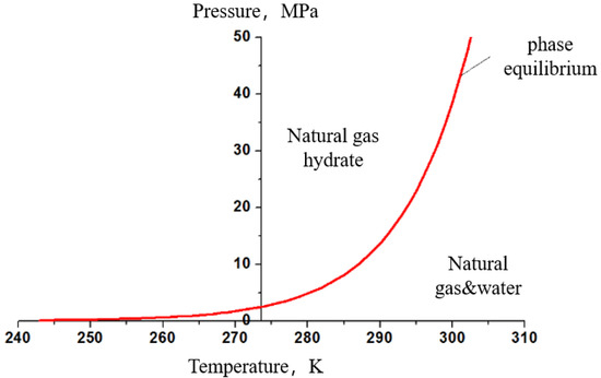
Figure 1.
Phase equilibrium curve of hydrate.
3. Simulation Experiments
3.1. Preparation of Hydrate Sediment
The mechanical characteristics of a hydrate reservoir can directly reflect the stability of the reservoir, and the experimental study can provide theoretical data guidance for the exploitation of hydrate. Therefore, hydrate core preparation with different components, water depth, and saturation is carried out, and physical parameters such as the saturation and permeability of the hydrate samples are tested. Meanwhile, the response relationship of hydrate’s mechanical properties under different conditions is studied, which is to provide theoretical data guidance for wellbore stability [28,29,30].
Based on marine site exploration, sediments act as the deposit carrier of marine gas hydrate. Their complex pore structure also plays an important role in controlling the formation and deposit of hydrate, and the size, shape, and components of sediment particles affect the growth of hydrate. Among them, the table of the particle size of common marine sedimentary layer rock and soil is shown in Table 1.

Table 1.
Particle size classification table of marine sediment.
Gas hydrate rock samples in the South China Sea were obtained during the deep-water engineering survey in the northern part of the South China Sea in recent years, and the data and distribution comparison of stratigraphic particle size distribution in the area were obtained by testing the gas hydrate rock samples, as shown in Table 2.

Table 2.
Particle size distribution of rock samples from cruise LW2-H4-1B/1C.
According to the comparison of the particle size distribution of the LW2-H4-1B/1C rock samples, it can be found that muddy silt sediment/sandy sediment is absolutely dominant in the marine hydrate reservoir, and the sedimentary particle size is mostly distributed in the range of 1~200 μm. In order to ensure a thorough experimental test, it has been determined that 120–180 m (80–120 mesh) quartz sand will be used for the simulation experiment of sandy sediment, while kaolin with a diameter of less than 5 m and quartz sand with a diameter of less than 50 m will be mixed in a specific proportion for the simulation experiment of muddy silt sediment.
The basic information on experimental materials is shown in Table 3. The sandy sediment is composed of 120~180 μm quartz sand, and the muddy silt sediment is composed of kaolin with a diameter of less than 5 μm and quartz sand with a diameter of less than 50 μm in a certain ratio (2:1). Firstly, the quartz sand of different particle sizes is screened by standard sieves. Secondly, the screened quartz sand (clayey powder sand) is directly loaded into the preparation kettle according to a certain ratio. Finally, the sand is compacted by loading axial pressure in the preparation kettle according to the experimental requirements, and the hydrate-containing cores are prepared by passing methane gas after compaction.

Table 3.
Basic information sheet of experimental materials.
According to the research content, the preparation of hydrate cores occurs with different components (muddy silt hydrate, sandy hydrate), water depths (300 m, 600 m, 900 m, 1200 m), temperatures (2 °C, 4 °C, 8 °C, 12 °C), pressures (5 MPa, 10 MPa, 12 MPa), and saturation (0~40%)/abundance (0~100%). Two experiments were conducted for each condition, and the results were averaged to ensure the accuracy and representativeness of the experimental results. The experimental schedule for core preparation and parameter testing is shown in Table 4.

Table 4.
Experimental schedule for core preparation and parameter testing.
3.2. Experimental Principle of Natural Gas Hydrate Parameters
3.2.1. Principles of Acoustic Testing
Acoustic logging technology is one of the most essential geophysical logging techniques. As distinct strata types or genesis have different mineral compositions, organizations, and structures, leading to variances in the strata’s elastic mechanical properties, different strata exhibit different acoustic propagation velocities, attenuation laws, and frequency characteristics. On the basis of the ideal elastomer theory in elastodynamics, it is assumed that the cores in the prepared kettle satisfy the following conditions: the cores of natural gas hydrate are continuous, homogenous, homogeneous, and fully elastic solid objects. The experiment measured and recorded the following acoustic properties of gas hydrate cores: longitudinal wave velocity and transverse wave velocity. The tests were conducted by loading the cores with the gas hydrate triaxial experimental system, and then measuring the transverse and longitudinal wave time differences as well as the transverse and longitudinal wave velocities of the gas hydrate cores with an acoustic measurement instrument. Following is the equation for transverse and longitudinal wave velocity:
where refers to the transverse wave velocity of the natural gas hydrate core, m/s; refers to the longitudinal wave velocity of the natural gas hydrate core, m/s; refers to the height of the gas hydrate core, m; refers to the time difference of the transverse waves in the gas hydrate core, s; the longitudinal wave time difference of the gas hydrate core, s.
3.2.2. Principle of Resistivity Testing
Resistivity logging is a traditional form of logging in oil fields. There are differences in the electrical conductivity of different formation rocks, and there are also significant differences in the resistivity of oil, gas, and water in the pores of the formation rocks; therefore, the formation resistivity can be measured to evaluate and classify the formation lithology and make determinations regarding oil and water formations, etc. To estimate the gas hydrate saturation, academics in related fields have developed, based on standard oil and gas resistivity logging, models suitable to gas hydrate reservoir resistivity logging, such as the Alchian formula, double water model, Waxman-Smits model, etc.
Based on the conventional Alchian equation, the equation for water saturation Sw in gas hydrate reservoirs was established based on the empirical equation between the resistivity and pore fluid saturation in the reservoir as shown in Equations (8) and (9) [31,32].
where refers to the reservoir water resistivity, Ω·m; a refers to the lithology-related lithology coefficient, about 0.6~1.5; m refers to cementation index; about 2; refers to the reservoir porosity; refers to the reservoir resistivity, Ω·m; n refers to the saturation index; refers to the thickness of the reservoir, m; A refers to the reservoir cross-sectional area, m2; R refers to the reservoir water resistance, Ω·m.
Then, the saturation of the water in the reservoir is obtained from Equations (8) and (9), and thus the saturation of the natural gas hydrate can be calculated as:
where refers to the natural gas hydrate saturation.
3.2.3. Principle of Mechanical Characteristics Testing
The mechanical parameters of natural gas hydrate reservoirs are the most direct indicator of reservoir stability and give direction for natural gas hydrate extraction. Throughout the experiment, axial deformation, radial deformation, axial pressure, and surrounding pressure data are collected. The axial pressure and surrounding pressure are then utilized to determine the natural gas hydrate core partial stress, and the core strain may be determined using the core axial deformation and the initial height value. The partial stress equations are as follows:
where refers to the bias stress, MPa; refers to the axial pressure, MPa; refers to the surrounding pressure, MPa.
The strain variables are calculated as follows:
where refers to the core height at 10 MPa of the axial pressure, mm; refers to the axial deformation of the core at 10 MPa axial pressure, mm; refers to the difference in the axial deformation of the core before and after loading, mm; refers to the axial deformation of the core at 30 MPa axial pressure, mm; refers to the nominal strain; refers to the real strain.
3.3. Evaluation Experiment of Hydrate Parameters
3.3.1. Experimental Device
The acoustoelectric and mechanical testing system for hydrate samples is depicted in Figure 2. The preparation system, temperature regulation system, mechanical testing system, acoustoelectric measurement system, fluid control system, and data acquisition control system are the five major components of the acoustoelectric and mechanical testing system for natural gas hydrate rock samples. This system is capable of the following operations.
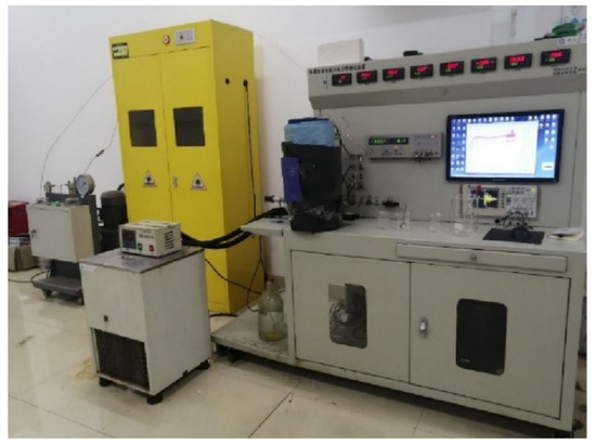
Figure 2.
The acoustoelectric and mechanical testing system of hydrate samples.
- Natural gas hydrate cores can be prepared by adding water and gas to the preparation kettle, and the experimental phenomena in the kettle can be observed and photographed during the preparation process;
- The preparation of gas hydrate cores with certain saturation by controlling the amount of water and gas injected;
- The measurement of changes in the acoustoelectric parameters during gas hydrate generation;
- The preparation of gas hydrate cores under specific temperature and pressure conditions;
- The measurement of the mechanical strength of gas hydrate cores by means of pressure regulation systems;
- The measurement of resolved gas volumes after the complete decomposition of gas hydrate cores.
Figure 3 illustrates the triaxial mechanical test system. The whole test device consists of four parts: a loading system, a specimen synthesis system, a temperature and pressure control system, and a measurement system. These four systems correspond to the functions of axial stress loading measurement and control, circumferential pressure value measurement and control, specimen temperature and test temperature measurement and control, equipment monitoring, data recording, etc. The axial loading system can provide an axial load of 0~1000 kN, a loading strain rate of 0.001~6 mm/min, a pore pressure range of 0~140 MPa, a temperature of −30~150 °C, a dynamic frequency of 10 Hz; experimental accuracy: pressure 0.01 MPa, liquid volume 0.01 cc, deformation 0.001 mm; clamping core sizes available: 1 inch, 1.5 inch, and 2 inch. In the process of the triaxial compression test, the mechanical parameters such as temperature, surrounding pressure, and strain can be collected and saved by a computer in real time. The apparatus can test hydrate cores for uniaxial compression, triaxial compression, elastic modulus, Poisson’s ratio, and tensile strength. Computers can capture and store mechanical characteristics such as temperature, circumferential pressure, and strain in real time during a triaxial compression test.
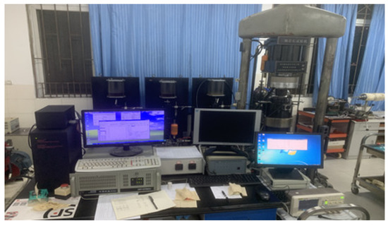
Figure 3.
Triaxial mechanical testing system.
3.3.2. Experimental Methods
The natural gas hydrate preparation process mainly includes five processes: sand filling, preparation kettle cooling, preparation kettle pressurization, evacuation, and preparation kettle injection. Sand filling provides the basis for gas hydrate core preparation; preparation kettle cooling controls the temperature inside the preparation kettle in the temperature range of gas hydrate generation; preparation kettle pressurization brings the pressure inside the preparation kettle to the pressure range of gas hydrate generation; evacuation is required to avoid the influence of air inside the preparation kettle on the gas hydrate preparation process; under suitable temperature and pressure conditions, the preparation kettle is filled with methane gas and deionized water for gas hydrate preparation. After the hydrate cores are prepared, the following parameter evaluation experiments will be conducted according to the purpose of the study.
- (1)
- Hydrate physical property parameter evaluation experiments:
- gas hydrate core parameters testing. The physical parameters are monitored during core preparation. The temperature and pressure parameters of the core in the preparation kettle are monitored from the beginning of the experiment, and the data measurement and acquisition of resistivity, acoustic, axial pressure, circumferential pressure, and axial deformation are also turned on. After installing the upper-end cover of the preparation kettle, connect the inlet pressure monitoring, acoustic emission, and camera connection lines to the relevant interfaces on the higher-end cover. Connect each monitoring instrument to the mechanical testing system’s data acquisition control model in order to monitor and record the cores’ temperature, pressure, resistance, and experimental test phenomena. Following the preparation of the gas hydrate cores, the cores are mechanically evaluated in triaxial compression studies. Conduct mechanical testing on the compression of the core. Keep the initial confining pressure and axial pressure unchanged, close the methane gas cylinder valve and prepare the gas injection pipeline valve, set the axial pressure loading rate in the data acquisition and control system to 1 mL/min, and change the original axial pressure value from 15 MPa to 1 mL/min. The axial pressure is set to 20 MPa~30 MPa within the pressure limit of the experimental device for loading (the specific axial pressure value depends on the actual situation), the core is compressively deformed during the axial pressure loading process, the initial axial pressure of 15 MPa is inputted in the control system for un-loading operation after the loading is completed, and the rebound characteristics of the hydrate core after deformation are measured after unloading. Variations in the mechanical parameters of each phase of the hydrate core are recorded by a computer, and the stress, strain, and compression properties of the hydrate are then studied using these data.
- After the acoustic, electrical resistance, strain, and generation phenomena data acquisition of the gas hydrate cores is completed, the hydrate core decomposition test phase is conducted, in which the volume of the consumed natural gas (analytical gas for natural gas hydrate decomposition) is measured using the drainage method, and the experimental setup is restored to its pre-experimental initial position after the measurement is completed in preparation for the next experiment.
- Repeated group experiments were conducted. After the completion of the experimental parameter test, the temperature in the kettle was raised without venting the analyzed gas to make the hydrate decompose, and then the temperature was lowered to re-generate the hydrate for the parameter test after the decomposition was completed. If the physical parameters of the hydrate measured for the second time are basically the same as those measured for the first time, the exhaust operation will be continued.
- (2)
- Hydrate mechanical properties test experiment:
After the hydrate core is prepared, it is wrapped in a 0.5 mm-thick rubber sleeve. The vent hole of the triaxial mechanical test system is opened, and hydraulic oil cooled to the set temperature is injected into the pressure chamber. When the hydraulic oil is continuously discharged from the venting hole, the pressure chamber has been filled with hydraulic oil. Close the air vent and turn on the thermostatic bath to control the oil temperature. Once the preparation is complete, the core is placed between the upper and lower pressure pads at a low temperature and then quickly placed into the pressure chamber of the triaxial system and secured to the positioning pins at the base of the pressure chamber to keep the specimen upright and stable. According to the experimental conditions, circumferential pressure is applied to compress the specimen to the pre-stressed state. After compressing the core, the desired parameters were set for triaxial compression experiments. During the experiment, the stress–strain curve and the experimental data are recorded. At the end of the experiment, the axial load and the surrounding pressure are removed. The shape of the specimen after damage was recorded and documented. The experimental process of specimen preparation and parameter evaluation is carried out strictly in accordance with the above steps, and the obtained experimental data had good repeatability.
3.4. Experimental Results
3.4.1. Hydrate Saturation
For the sandy sediment, the relationship between the hydrate saturation and the volume of the resolved gas under the same temperature and different pressure conditions was compared. The variation of the resolved gas with hydrate saturation under different pressure conditions of 2 °C, 4 °C, 8 °C, and 12 °C is shown in Figure 4.
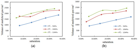
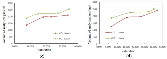
Figure 4.
Relationship between analytical gas and saturation of hydrates (a) The test temperature is 2 °C; (b) The test temperature is 4 °C; (c) The test temperature is 8 °C; (d) The test temperature is 12 °C.
It can be found from the graphs that the variation patterns of the resolved gas volume with hydrate saturation are similar in the three conditions; the resolved gas volume increases with hydrate saturation at the same temperature and constant pressure, and the resolved gas volume increases with pressure at the same temperature and saturation. However, under the same conditions, the variation and inhomogeneous generation of hydrate components at high pressure can affect the pore connectivity, making some of the aqueous solutions not fully reacted, resulting in the irregular and non-linear amplitude of the curve change. No hydrate is produced at 8 °C, 12 °C, and 5 MPa.
For the muddy silt sediment, the relationship between hydrate saturation and the volume of resolved gas under the same pressure and different temperatures is compared. The variation of the resolved gas with hydrate saturation under different temperatures of 5 MPa and 12 MPa is shown in Figure 5.
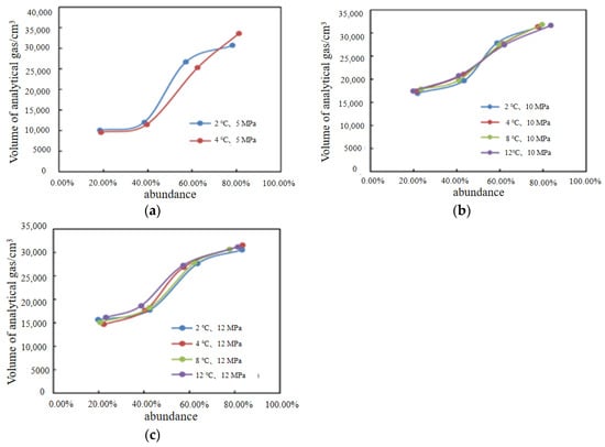
Figure 5.
Relationship between analytical gas and abundance of hydrates (a) The test pressure is 5 MPa; (b) The test pressure is 10 MPa; (c) The test pressure is 12 MPa.
It can be found from the figure that the variation pattern of the resolved gas volume with hydrate saturation is similar in the three conditions; the resolved gas volume increases with the increase in hydrate saturation at the same temperature and constant pressure, and the resolved gas volume increases with the increase in temperature at the same pressure and saturation. No hydrate is produced at 8 °C, 12 °C, and 5 MPa.
3.4.2. Hydrate Resistivity
For the sandy sediment, the resistivity data of cores with different particle sizes, temperatures, pressures, and saturation were analyzed and tested. It can be found that the resistivity of the cores with different temperatures, pressures, and saturation varied to a certain extent, as shown in Figure 6.
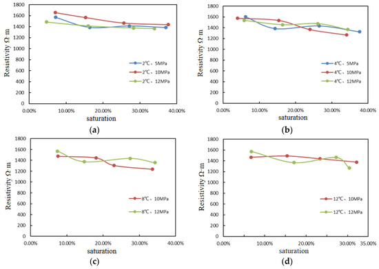
Figure 6.
Relationship between resistivity and saturation of hydrates (a) The test temperature is 2 °C; (b) The test temperature is 4 °C; (c) The test temperature is 8 °C; (d) The test temperature is 12 °C.
Due to the fact that the resistivity of hydrate is substantially lower than the resistivity of the core skeleton, the graph demonstrates that the resistivity of the core reduces with increasing hydrate saturation under varied temperature and pressure circumstances. The resistivity of the cores ranged between 1300 Ω·m and 1700 Ω·m under the experimental conditions of temperature and pressure. This differs from the previously reported resistivity variation pattern of hydrates, in which researchers discovered that in hydrate reservoirs saturated with water, the hydrate resistivity increased with increasing hydrate saturation. This is because the resistivity of hydrates is significantly greater than that of aqueous solutions; hence, the resistivity of hydrates increases with increasing saturation. In the investigations of this thesis, hydrate cores of a specific saturation were created using quantitative aqueous solutions, and the addition of aqueous solutions led the cores’ resistivity to decrease significantly. Additionally, during the process of generating hydrate of a particular saturation, the aqueous solution in the core is consumed, which increases the core’s resistance. Eventually, the water solution in the core is consumed, filling the core’s pores with methane gas and hydrate and stabilizing the core’s resistivity. The methane resistivity is greater than the hydrate resistivity, and as the hydrate saturation grows, the volume of methane gas in the pores of the core decreases, resulting in the phenomenon of the decreasing resistivity of hydrate cores with increasing saturation.
As for muddy silt hydrate, the resistivity data of cores with different particle sizes, temperatures, pressure, and saturation are analyzed and tested, and it can be found that the resistivity of cores with different temperatures, pressures, and saturation has certain variation rules, as shown in Figure 7.
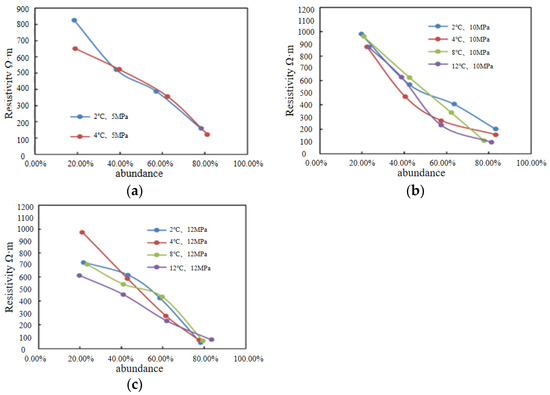
Figure 7.
Relationship between the resistivity and saturation of hydrates (a) The test pressure is 5 MPa; (b) The test pressure is 10 MPa; (c) The test pressure is 12 MPa.
According to the analysis, the resistivity of the core lowers as the hydrate saturation increases under varying temperature and pressure circumstances. This is because the resistivity of hydrate is substantially lower than that of the core skeleton. When the hydrate mass abundance is between 20% and 80%, the resistivity of the core fluctuates between 0 Ω·m and 1000 Ω·m. Similar to sand-based hydrates, the changes in the resistivity variation patterns of muddy silt hydrates compared to earlier hydrate-related studies have similar causes.
3.4.3. Hydrate Wave Velocity
For the sandy sediment, the transverse and longitudinal waves of the cores in the kettle were measured by the hydrate sample testing device, and the transverse and longitudinal wave data were measured experimentally after calculation and processing. The wave speed of cores with different temperatures and pressures has a certain variation pattern, as shown in Figure 8.
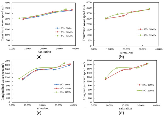
Figure 8.
Variation of wave velocity with saturation (a) Transverse wave, temperature is 2 °C; (b) Transverse wave, temperature is 8 °C; (c) Longitudinal wave, temperature is 2 °C; (d) Longitudinal wave, temperature is 8 °C.
Transverse and longitudinal wave velocities rise with the increase in hydrate saturation under the same temperature and pressure. The transverse wave velocity ranges from 2500 to 3500 m/s, and the longitudinal wave velocity ranges from 1000 to 1900 m/s when the saturation is between 0% and 40%. In general, the range of wave velocity does not change greatly under varied temperature and pressure settings; under conditions of equal temperature, experimental cores with higher pressure have greater transverse and longitudinal wave velocities.
As for muddy silt hydrate, the same experimental procedure as above for sandy hydrate is used. The wave speed of cores with different temperatures and pressures has a certain variation pattern, as shown in Figure 9.
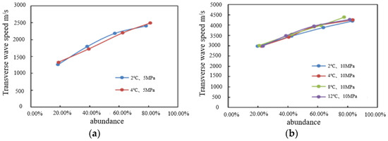
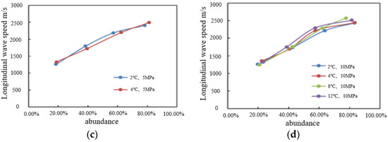
Figure 9.
Variation of wave velocity with abundance (a) Transverse wave, pressure is 5 MPa; (b) Transverse wave, pressure is 10 MPa; (c) Longitudinal wave, pressure is 5 MPa; (d) Longitudinal wave, pressure is 5 MPa.
According to the analysis, the transverse and longitudinal wave velocities increase with the increase in hydrate saturation at the same temperature and pressure. The transverse wave velocity ranges from 3000 to 4500 m/s when the mass abundance is between 20% and 40%, while the longitudinal wave velocity ranges from 1200 to 2500 m/s when the mass abundance is between 20% and 80%. In general, the range of wave velocity does not vary greatly under varied temperature and pressure settings; under conditions of equal temperature, experimental cores with a higher pressure exhibit greater transverse and longitudinal wave velocities.
The sandy hydrate system reflects higher transverse and longitudinal wave velocity under the same temperature conditions when the pressure is higher, and the transverse wave velocity of the hydrate system of the sandy system is greater than the longitudinal wave velocity under the same saturation; the sound velocity of the core increases with the increase in pressure and decrease in temperature, and when the pores of the core are filled with hydrate, the sound velocity decreases. Both the transverse and longitudinal wave velocities of the hydrate cores of a muddy silt system increase with mass abundance; under the same temperature, pressure, and saturation, the transverse wave velocity is greater than the longitudinal wave velocity.
3.4.4. Stress–Strain Curves of Cores at Different Temperatures
Figure 10 shows the stress–strain curves of sandy sediment cores at different temperatures when the hydrate saturation is 5% and the pore pressure is 5 MPa, 10 MPa, and 12 MPa, respectively.
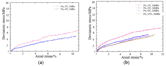
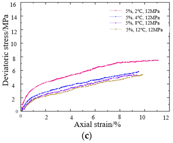
Figure 10.
Core stress–strain curves at different temperatures (saturation 5%) (a) The test pressure is 5 MPa; (b) The test pressure is 10 MPa; (c) The test pressure is 12 MPa.
The analysis of the graph reveals that the stiffness and strength of sandy hydrate cores drop significantly as the temperature rises. Additionally, the gas hydrate will not form at pressures of 5 MPa and temperatures of 8 °C and 12 °C. When the temperature is 2 °C, the partial stress of sandstone hydrate cores in the small strain range (axial strain 1%) is 1.9 MPa, 2.8 MPa, and 3.2 MPa, respectively, at different pore pressures; when the temperature is 4 °C, the partial stress of sandstone hydrate cores in the small strain range (axial strain 1%) decreases to 1 MPa, 1.5 MPa, and 2.1 MPa.
Figure 11 shows the stress–strain curves of a muddy silt sediment core at different temperatures when the abundance is 20% and the pore pressure is 5 MPa, 10 MPa, and 12 MPa, respectively.
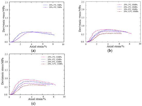
Figure 11.
Core stress–strain curves at different temperatures (abundance 20%) (a) The test pressure is 5 MPa; (b) The test pressure is 10 MPa; (c) The test pressure is 12 MPa.
The analysis of the graph indicates that the stiffness and strength of muddy silt hydrate cores diminish significantly as the pressure increases. When the pressure was 5 MPa, the stresses in the small strain region (axial strain 1%) of the muddy silt hydrate cores at different temperatures were 0.23 MPa and 0.11 MPa, respectively, and their peak strengths were 0.65 MPa and 0.55 MPa, followed by the strain softening of their cores. When the pressure reaches 10 MPa, the partial stresses in the small strain range (axial strain 1%) of the muddy silt hydrate cores at different temperatures are 0.27 MPa, 0.17 MPa, 0.10 MPa, and 0.06 MPa, and the peak strengths are 0.75 MPa, 0.7 MPa, 0.68 MPa, and 0.55 MPa, followed by strain softening in its sandstone core. At 12 MPa, the partial stresses in the small strain range (axial strain 1%) of muddy silt hydrate cores at different temperatures are 0.5 MPa, 0.3 MPa, 0.25 MPa, and 0.06 MPa, and their peak strengths are 0.70 MPa, 0.62 MPa, 0.70 MPa, and 0.62 MPa, followed by the strain softening of their cores.
3.4.5. Stress–Strain Curves of Cores at Different Pressures
Figure 12 shows the stress–strain curves of sandy sediment cores under different pressure conditions when the hydrate saturation is 5% and the temperature is 2 °C, 4 °C, 8 °C and 12 °C, respectively.
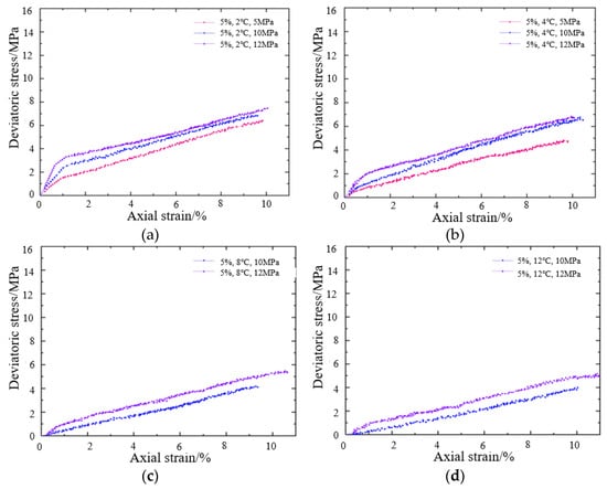
Figure 12.
Core stress–strain curves at different temperatures (saturation 5%) (a) The test temperature is 4 °C; (b) The test temperature is 4 °C; (c) The test temperature is 8 °C; (d) The test temperature is 12 °C.
As depicted in the graph, the stiffness and strength of sandy sediment cores increase significantly with increasing pressure. When the pressure is 10 MPa, the small strain range (axial strain 1%) sandstone hydrate core partial stresses at different temperatures are 2.1 MPa, 0.9 MPa, 0.3 MPa, and 0.2 MPa; when the pressure is 12 MPa, the small strain range (axial strain 1%) sandstone hydrate core partial stresses increased to 2.4 MPa, 2 MPa, 0.9 MPa, and 0.3 MPa at different temperatures, respectively.
Figure 13 shows the stress–strain curves of muddy silt sediment cores under different pressure conditions when the abundance is 20% and the reservoir temperature is 4 °C and 12 °C, respectively.
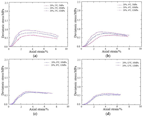
Figure 13.
Core stress–strain curves at different pressures (abundance 20%) (a) The test temperature is 4 °C; (b) The test temperature is 4 °C; (c) The test temperature is 8 °C; (d) The test temperature is 12 °C.
As seen in the graph, the stiffness and strength of the muddy silt sediment cores rise significantly as the pressure increases. At 5 MPa, the stresses in the small strain region (axial strain 1%) of the muddy silt hydrate cores at different temperatures were 0.23 MPa and 0.11 MPa, and the peak strengths were 0.65 MPa and 0.55 MPa, followed by the strain softening of the cores. When the pressure reaches 10 MPa, the partial stresses in the small strain range (axial strain 1%) of the muddy silt hydrate cores at different temperatures are 0.27 MPa, 0.17 MPa, 0.10 MPa, and 0.06 MPa, respectively, and the peak strengths are 0.75 MPa, 0.7 MPa, 0.68 MPa, and 0.55 MPa, respectively, after which strain softening occurs in the core. When the pressure is 12 MPa, the partial stresses in the small strain range (axial strain 1%) of the clayey silt hydrate cores at different temperatures are 0.5 MPa, 0.3 MPa, 0.25 MPa, and 0.06 MPa, respectively, and the peak strengths are 0.70 MPa, 0.62 MPa, 0.70 MPa, and 0.62 MPa, respectively, followed by the strain softening in the cores.
By observing the experimental results, it can be seen that the stresses in sandy hydrate and muddy siltstone cores rise rapidly with the increase in saturation and pore pressure and the decrease in temperature, and there are obvious inflection points. For sandy hydrate cores, the influence of saturation on the strain hardening and strain softening of the sandy hydrate cores is large, and the stiffness and strength show a significant increase with the increase in saturation. For muddy silt hydrate cores, there is a significant increase in the bias stress of muddy silt hydrate cores with increasing hydrate mass abundance under the same strain conditions. In the low-temperature environment, as the temperature decreases, the hydrate core strength then increases, and the strain softening trend gradually decreases. As the prepared hydrate cores are occupied by ice inside a certain space, when the temperature is slightly higher, the ice particles in the hydrate will melt, leading to a decrease in the strength of the whole hydrate core.
4. Evolutionary Model of Hydrate Mechanical Properties with Temperature–Pressure Variation
Current tests have shown that ambient temperature and pore pressure have significant effects on the rigidity and strength of natural gas hydrates. In other words, the stiffness and strength of sediments containing hydrates will increase significantly as the temperature and pore pressure decrease. The strength of sediments containing hydrate is largely determined by the combination of the strength of the hydrate and the strength of the cementation at the interface of the hydrate particles and the soil particles.
4.1. Evolutionary Model Principles
The mechanical properties of hydrate-bearing sediments in the formation are intimately connected to temperature and pressure conditions, grain size, and saturation. The project establishes a model for the evolution of the mechanical properties of hydrate-bearing sediments with temperature and pressure on the basis of the theory of continuum damage mechanics, introduces temperature and pressure parameters that can account for the effects of temperature and pore pressure, determines the elastic model of hydrate-bearing sediments, and obtains the evolution law of hydrate-bearing mechanical properties with temperature and pressure. The model is constructed as follows:
where: is the strain: is the apparent modulus of elasticity; is the actual modulus of elasticity of the material, and both and are fourth-order tensors; is the effective stress, second-order tensor; and is the damage variable and is a scalar.
In order to describe the effect law of temperature and pore pressure on the mechanical properties of hydrates, a state parameter was used to describe the temperature and pore pressure conditions and the temperature–pressure condition parameter [33]:
where: is the ambient temperature; is the phase equilibrium temperature corresponding to the hydrate when the pore pressure is , which mainly describes the temperature when the hydrate phase changes; is the reference temperature, which is taken as 273.15 K.
Assuming that the micro-element intensity of hydrate-bearing sediments obeys the generalized Hooke’s law and obeys the statistical law of Weibull distribution, the probability density model of its distribution can be obtained as [34]:
It is assumed that the strength of the microelements of hydrate-bearing sediments obeys the generalized Hooke’s law and obeys the statistical law of Weibull distribution. During the loading process of the hydrate-containing sediments, their microelements are destroyed sequentially according to their strengths, thus causing a continuous damage process. The ratio of the number of damaged microelements to the total number of microelements in this damage process is called the damage variable and can be expressed as [35]:
where: is the damage variable, which represents the ratio of the number of damaged microelements to the total number of microelements; is the microelement strength of the hydrate-bearing sediment; m and are the Weibull distribution parameter, which is controlled by the material properties of the hydrate-bearing sediment and is closely related to the sediment properties, hydrate content, surrounding pressure, temperature and pressure conditions, etc.
This leads to the following model for the evolution of hydrate mechanical properties with a temperature–pressure variation.
where is the modulus of elasticity, MPa; is Poisson’s ratio of the soil; is the test envelope pressure, MPa; is the material parameter.
In summary, the model is intended to establish the relationship between pressure and temperature through the phase equilibrium model; combine the temperature and pressure parameters to establish the relationship between temperature and mechanical parameters (fitted with experimental data); establish the relationship between other parameters and temperature and pressure conditions; and finally, obtain the model of the stress–strain relationship affected by temperature and pressure.
4.2. Sandy Sediment
The peak strength, Poisson’s ratio, Young’s modulus, and bulk modulus of sandy hydrate cores with temperature and pressure are shown in Figure 14.
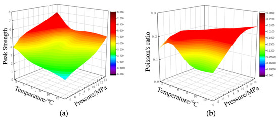
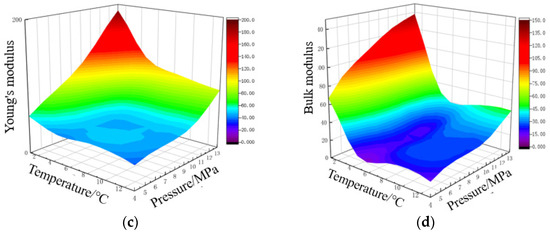
Figure 14.
Variation of mechanical properties of sandy hydrate with temperature and pressure (a) Peak Strength; (b) Poisson’s ratio; (c) Young’s modulus; (d) Bulk modulus.
4.3. Muddy Silt Sediment
The peak strength, Poisson’s ratio, Young’s modulus, and bulk modulus of muddy silt hydrate cores with temperature and pressure are shown in Figure 15.
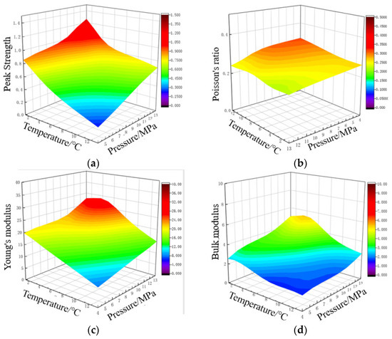
Figure 15.
Variation of mechanical properties of muddy silt hydrate with temperature and pressure (a) Peak Strength; (b) Poisson’s ratio; (c) Young’s modulus; (d) Bulk modulus.
When the saturation/mass abundance is constant, the peak core strength tends to decrease with increasing temperature and lowering pressure, as demonstrated by the comparisons above. Under experimental settings, the peak strength of sandy hydrate varies between 6.9 and 13.1 MPa, whereas the peak strength of muddy silt hydrate varies between 0.77 and 1.5 MPa. Temperature and pressure have a bigger impact on the elastic modulus than Poisson’s ratio. Under experimental conditions, Poisson’s ratio of sandy hydrate ranged between 0.12 and 0.18, and Poisson’s ratio of muddy silt hydrate ranged between 0.15 and 0.24; the elastic modulus of sandy hydrate ranged from 17.4 to 130.9 MPa, and the elastic modulus of muddy silt hydrate ranged from 21.5 to 47.4 MPa. The sandy hydrate bulk modulus varied between 45.3 to 393.9 MPa. The bulk modulus of muddy silt hydrate varies between 3.7 and 11.1 MPa. Temperature and pressure variations have a greater impact on the mechanical characteristics of sandy sediment.
5. Conclusions
Through the research, the conclusions were as follows:
- At the same temperature, the hydrate core with the greater pressure has faster transverse and longitudinal wave speeds. Under the same saturation, the transverse wave velocity of sandy hydrate is greater than the longitudinal wave velocity; at a particular particle size of quartz sand, both transverse and longitudinal wave velocities increase with increasing saturation; the wave velocity of sandy hydrate is positively correlated with pressure and negatively correlated with temperature. The transverse and longitudinal wave velocities of muddy silt hydrate cores increase with the increase in mass abundance when the ratio of quartz sand and kaolinite is held constant; the transverse wave velocity of muddy silt hydrate cores is greater than the longitudinal wave velocity at the same temperature, pressure, and saturation; the influence on its core acoustic wave velocity is small and does not exhibit a particular pattern in the temperature and pressure range of the test.
- The resistivity of sandy hydrate cores varies little between 0% and 40% saturation, and it reduces somewhat with increasing hydrate saturation; the resistivity of the muddy silt hydrate cores decreases with increasing mass abundance. The resistivity data at different temperatures and pressures demonstrate that the resistivity of cores reduces as hydrate saturation increases and that the change trend is more regular, which can be used as a data reference for reservoir exploration and the logging of marine gas hydrate.
- For sandy sediment, as the saturation level rises, the core’s stiffness and strength increase dramatically. For muddy silt sediment, the deviatoric stress of the muddy silt sediment core increases dramatically as the hydrate mass abundance increases under the same strain situation. With increasing saturation and pore pressure and decreasing temperature, the stress of sandy and muddy silt increases rapidly under the same strain situation, and there is a distinct inflection point; after reaching a specific temperature, it does not form hydrate. Among them, saturation has a major effect on the strain and strain of sandy sediment; as the saturation increases, its stiffness and strength increase dramatically, although it has little effect on the hydration of muddy silts. As the temperature drops, the free water in the hydrate sediment crystallizes into icier particles. Due to the fact that a rise in ice particles can serve as the specimen’s skeleton, thereby distributing the specimen’s external stress and raising the cementation force between sediment particles, it is possible to increase the core damage strength.
Author Contributions
Conceptualization, L.W.; Data curation, J.Y.; Investigation, L.L.; Methodology, T.S.; Project administration, D.X. All authors have read and agreed to the published version of the manuscript.
Funding
The Sub-Project of National Key R&D Program: The risk identification and prevention technology of shallow geological disaster in drilling in Arctic region. Number: 2022YFC28064001.
Data Availability Statement
The study did not report any data.
Conflicts of Interest
The authors declare no conflict of interest.
References
- Sloan, E.D. Natural Gas Hydrates. J. Pet. Technol. 1991, 43, 1414–1417. [Google Scholar] [CrossRef]
- Gift, J.H.; Hosein, R.; Jupiter, A.; Wang, J.Y. Natural Gas Resource from Gas Hydrates Offshore the East Coast of Trinidad. SPE J. 2022, 27, 2926–2940. [Google Scholar] [CrossRef]
- Lau, H.C.; Wang, J.; Zhang, M. A New Classification of Gas-Hydrate Deposits and Its Implications for Field-Development Potential. SPE J. 2021, 26, 3643–3667. [Google Scholar] [CrossRef]
- Carpenter, C. Report Outlines Knowledge Gained in Gas Hydrate Production Testing. J. Pet. Technol. 2020, 72, 58–59. [Google Scholar] [CrossRef]
- Beauchamp, B. Natural gas hydrates: Myths, facts and issues. Comptes Rendus Geosci. 2004, 336, 751–765. [Google Scholar] [CrossRef]
- Veluswamy, H.P.; Kumar, A.; Seo, Y.; Lee, J.D.; Linga, P. A review of solidified natural gas (SNG) technology for gas storage via clathrate hydrates. Appl. Energy 2018, 216, 262–285. [Google Scholar] [CrossRef]
- Barker, J.W.; Gomez, R.K. Formation of Hydrates during Deepwater Drilling Operations. J. Pet. Technol. 1989, 41, 297–301. [Google Scholar] [CrossRef]
- Wang, Q.; Wang, R.; Sun, J.; Sun, J.; Lu, C.; Lv, K.; Wang, J.; Wang, J.; Yang, J.; Qu, Y. Effect of Drilling Fluid Invasion on Natural Gas Hydrate Near-Well Reservoirs Drilling in a Horizontal Well. Energies 2021, 14, 7075. [Google Scholar] [CrossRef]
- Lau, H.C.; Zhang, M.; Wang, J.; Pan, L. Some Technical Considerations of Gas-Hydrate Development from Chinese Permafrost Regions. SPE Reserv. Eval. Eng. 2020, 23, 369–387. [Google Scholar] [CrossRef]
- Waite, W.F.; Santamarina, J.C.; Cortes, D.D.; Dugan, B.; Espinoza, D.N.; Germaine, J.; Jang, J.; Jung, J.W.; Kneafsey, T.J.; Shin, H.; et al. Physical properties of hydrate-bearing sediments. Rev. Geophys. 2009, 4, 465–484. [Google Scholar] [CrossRef]
- Sergeeva, D.; Istomin, V.; Chuvilin, E.; Bukhanov, B.; Sokolova, N. Influence of Hydrate-Forming Gas Pressure on Equilibrium Pore Water Content in Soils. Energies 2021, 14, 1841. [Google Scholar] [CrossRef]
- Yuan, Y.; Xu, T.; Xia, Y.; Xin, X. Comparison of Simplistic and Geologically Descriptive Production Modeling for Natural-Gas Hydrate by Depressurization. SPE J. 2019, 24, 563–578. [Google Scholar] [CrossRef]
- Zhou, S.S.; Li, M.; Wu, P.; Liu, Y.; Zhang, L.X.; Yang, L.; Li, Y.H.; Zhao, J.F.; Song, Y.C. Permeability Analysis of Hydrate-Bearing Porous Media Considering the Effect of Phase Transition and Mechanical Strain during the Shear Process. SPE J. 2022, 27, 422–433. [Google Scholar] [CrossRef]
- Hyodo, M.; Nakata, Y.; Yoshimoto, N.; Fukunaga, M.; Kubo, K.; Nanjo, Y.; Matsuo, T.; Hyde, A.F.L.; Nakamura, K. Triaxial compressive strength of methane hydrate. In Proceedings of the Twelfth International Offshore and Polar Engineering Conference, Kitakyushu, Japan, 26–31 May 2002. [Google Scholar]
- Clayton, C.R.I.; Priest, J.A.; Best, A.I. The effects of disseminated methane hydrate on the dynamic stiffness and damping of a sand. Geotechnique 2005, 55, 423–434. [Google Scholar] [CrossRef]
- Sun, H.; Ren, W.; Jianhua, W.; Xianguang, X.; Fulong, N.; Dongdong, G. Effects of polyvinylpyrrolidone with different molecular weights on the formation and growth of tetrahydrofuran hydrate. J. Nat. Gas Ind. 2018, 38, 125–132. [Google Scholar]
- Wang, Y.H.; Leung, S.C. A particulate-Scale investigation of cemented sand behavior. Can. Geotech. J. 2008, 45, 29–44. [Google Scholar] [CrossRef]
- Jiang, M.; Zhang, W. Distinct element method investigation on mechanical behavior within shear bands in granulates under the Earth and the Moon conditions. Theor. Appl. Mech. Lett. 2013, 3, 02100. [Google Scholar] [CrossRef]
- Rutqvist, J.; Moridis, G.J.; Grover, T.; Silpngarmlert, S.; Collett, T.S.; Holdich, S.A. Coupled multiphase fluid flow and wellbore stability analysis associated with gas production from oceanic hydrate-bearing sediments. J. Pet. Sci. Eng. 2012, 92, 65–81. [Google Scholar] [CrossRef]
- Freij-Ayoub, R.; Tan, C.; Clennell, B.; Tohidi, B.; Yang, J. A wellbore stability model for hydrate bearing sediments. J. Pet. Sci. Eng. 2007, 57, 209–220. [Google Scholar] [CrossRef]
- Winters, W.J. Physical properties of sediments from the JAPEX/JNOC/GSC Mallik 2L-38 gas hydrate research well. Bull. Geol. Surv. Can. 1999, 544, 95–100. [Google Scholar]
- Rutqvist, J.; Moridis, G.J. Numerical Studies on the Geomechanical Stability of Hydrate-Bearing Sediments. SPE J. 2009, 14, 267–282. [Google Scholar] [CrossRef]
- Winters, W.J.; Waite, W.F.; Mason, D.H.; Gilbert, L.Y.; Pecher, I.A. Methane gas hydrate effect on sediment acoustic and strength properties. J. Pet. Sci. Eng. 2007, 56, 127–135. [Google Scholar] [CrossRef]
- Kim, H.C.; Bishnoi, P.R.; Heidemann, R.A.; Rizvi, S.S. Kinetics of methane hydrate decomposition. Chem. Eng. Sci. 1987, 42, 1645–1653. [Google Scholar] [CrossRef]
- Platteeuw, J.C.; Van der Waals, J.H. Thermodynamic properties of gas hydrates. Mol. Phys. 1958, 1, 91–96. [Google Scholar] [CrossRef]
- Jhvd, W.; Platteeuw, J.C. Clathrate Solutions; Wiley-Blackwell: New York, NY, USA, 2007. [Google Scholar]
- Javanmardi, J.; Partoon, B.; Sabzi, F. Prediction of hydrate formation conditions based on vdWP type models at high pressures. Can. J. Chem. Eng. 2011, 89, 254–263. [Google Scholar] [CrossRef]
- Collet, T.S.; Ladd, J. Detection of gas hydrates with downhole logs and assessment of gas hydrate concentrations (saturations) and gas volumes on the Blake Ridge with electrical resistivity log data. In Proceedings of the Ocean Drilling Program, Scientific Results, Texas A&M University, College Station, TX, USA, 3 January–2 March 2001; Volume 164, pp. 179–191. [Google Scholar]
- Fu, W.; Wang, Z.; Chen, L.; Sun, B. Experimental Investigation of Methane Hydrate Formation in the Carboxmethylcellulose (CMC) Aqueous Solution. SPE J. 2020, 25, 1042–1056. [Google Scholar] [CrossRef]
- Benmesbah, F.D.; Ruffine, L.; Clain, P.; Osswald, V.; Fandino, O.; Fournaison, L.; Delahaye, A. Methane Hydrate Formation and Dissociation in Sand Media: Effect of Water Saturation, Gas Flowrate and Particle Size. Energies 2020, 13, 5200. [Google Scholar] [CrossRef]
- Sun, J.G. Archie’s formula: Historical background and earlier debates. Prog. Geophys. 2007, 22, 472–486. [Google Scholar]
- Fan, Y.; Deng, S.; Zhou, C. On the Parameters of Archie Formula for Shaly Sand with Low Salinity. Well Logging Technol. 1997, 21, 200–204. [Google Scholar]
- Lai, C.D.; Min, X.; Murthy, D. A modified Weibull distribution. IEEE Trans. Reliab. 2003, 52, 33–37. [Google Scholar] [CrossRef]
- Dell’Isola, F. Generalized Hooke’s law for isotropic second gradient materials. In Proceedings of the Royal Society A: Mathematical, Physical & Engineering Sciences. Proc. R. Soc. A. 2009, 465, 2177–2196. [Google Scholar] [CrossRef]
- Yu, T.T.J.G.; Teng, J.G.; Wong, Y.L.; Dong, S.L. Finite element modeling of confined concrete-I: Drucker–Prager type plasticity model. Eng. Struct. 2010, 32, 665–679. [Google Scholar] [CrossRef]
Publisher’s Note: MDPI stays neutral with regard to jurisdictional claims in published maps and institutional affiliations. |
© 2022 by the authors. Licensee MDPI, Basel, Switzerland. This article is an open access article distributed under the terms and conditions of the Creative Commons Attribution (CC BY) license (https://creativecommons.org/licenses/by/4.0/).