Review

Fuel-Water Emulsion as an Alternative Fuel for Gas Turbines in the Context of Combustion Process Properties—A Review

1
Department of Composite Aviation Structures, Air Force Institute of Technology, 01-494 Warsaw, Poland
2
Department of Division of Aircraft Engines, Warsaw University of Technology, 00-661 Warsaw, Poland
*
Author to whom correspondence should be addressed.
Energies 2022, 15(23), 8979; https://doi.org/10.3390/en15238979
Submission received: 27 October 2022 / Revised: 19 November 2022 / Accepted: 23 November 2022 / Published: 28 November 2022
(This article belongs to the Section I1: Fuel)

Abstract

:
Fuel with the addition of water, forming fuel-water emulsions, is a potential way to reduce the emission of pollutants from gas turbines powered by any liquid fuel. This article analyzes the available work on the combustion of fuel-water emulsions in gas turbines. The literature analysis was preceded by a theoretical introduction on fuel-water emulsion, taking into account the factors influencing its micro- and macroscopic properties. The basic features of the agents used to stabilize the emulsion were also discussed and the process of its combustion was described. The analyzed research differed in terms of the test stands on which the experiments were conducted, the fuel constituting the continuous phase of the emulsion, the amount of water contained in the mixture and the method of producing the emulsion. On the basis of the conducted analysis, conclusions were drawn concerning the influence of feeding a gas turbine with a fuel-water emulsion on the emission of nitrogen oxides, carbon monoxide and exhaust smoke. Conclusions were formulated regarding the influence of the water additive to fuel-on-fuel consumption. In addition, the impact of the presence of water on the conversion of nitrogen contained in the fuel to nitrogen oxides was indicated, and areas requiring further research were presented.

1. Introduction

The U.S. Energy Information Administration report clearly states that the predicted global primary energy consumption until 2050 is going to increase by approximately 50%, up to 2.64 × 10⁸ GWh, of which 49% will be covered by natural gas, petroleum products and other liquid fuels such as biofuels [1]. It is going to happen despite strenuous attempts to restrict human impact on the earth’s climate [2,3,4].
The Copenhagen Accord, the Cancún Agreements and the Durban Platform arrangements aim to reduce greenhouse gas emissions to the level assuring an average earth temperature increase of maximum 2 degrees Celsius compared to the pre-industrial era [3]. During the 2015 Paris Climate Change Conference: COP21 it was proposed to limit the threshold of a maximum temperature increase to max. 1.5 degrees Celsius [4].
In 2008, the Marine Environment Protection Committee, as a part of the amendment of the VI annex to the International Convention for the Prevention of Pollution from Ships, has accepted the regulations restricting emission levels from ships. Among other things, they related this to NO x emissions (Regulation 13), which current limits are dependent on the year of the ship build and the ship’s diesel engine rotational speed. Limits mentioned in the above document are divided into three Tiers which depend on the shipping area [2]. Despite an introduction of the stringent standards, total shipping-related emissions will increase as a result of increasing tonnage [5]. An extensive research campaign was carried out to reduce emissions caused by shipping as a result of increasing environmental requirements. One of the considered concepts is the replacement of diesel engines with gas turbines (GT), which can be a source of energy and propulsion for ships [6,7,8,9].
Without a significant contribution from the aviation sector [10], the global targets for limiting climate change cannot be met. In air transport, aviation gas turbines, mainly turbofan engines, play a dominant role [11]. Despite the international consensus on the need to reduce greenhouse gas emissions, it is forecasted that the increase in CO2 and NO x emissions from the aviation sector in 2050 may increase by 3.6× and 2.7×, respectively, compared to the year 2000 [12]. Significant research effort is put into reducing emissions and increasing the efficiency of aviation GT [13,14,15,16,17,18,19].
Gas Turbines are widely used in the power industry [20,21,22,23,24]. This is because gas turbines are characterized by relatively high efficiency, low unit investment costs (cost/kW), high power-to-weight ratio and low pollutant emissions [25]. One of the recent trends aiming to reduce CO2 emissions from gas turbines is the use of biofuels that are produced and burned in a closed carbon cycle [26,27]. Gas turbines are multi-fueled which makes it possible to use non-fossil fuels. Currently, scientific research on the use of biofuels as gas turbine fuel are being conducted [28,29,30,31,32,33]. Hydrogen seems to be an alternative fuel with high potential, especially in the context of decarbonization. The product of complete combustion of hydrogen in pure oxygen is water [34]. Moreover, hydrogen is characterized by a lower heating value (LHV) of 120 MJ/kg, which is about three times higher compared to conventional hydrocarbon fuels. Scientific research to verify the potential of hydrogen use in reciprocating engines [35,36] and gas turbine [37,38] is ongoing. Recent research on the combustion of ammonia in GT and piston engines indicates that ammonia will be an important element of the future energy mix [39].
For the above-mentioned reasons, gas turbines will increase their share in transport and energy production during the long-term process of industry decarbonization. Regardless of the type of fuel and its efficiency, as long as the oxygen necessary to carry out the combustion reaction comes from the air, we will struggle with the emission of NO x to the atmosphere. Human presence in an area with an increased concentration of nitrogen oxides in the atmosphere is detrimental to health. It causes a decrease in lung function, asthma attacks and many other ailments [40], which may lead to premature death [41].
Most of the NO x created inside a gas turbine combustion chamber is generated according to the Zeldovich mechanism, and the rate of their formation depends almost exclusively on the fuel residence time in the reaction zone and temperature [42]. Therefore, in order to reduce NO x emissions from GT, the focus should be on controlling the temperature (precisely reducing it) in the combustion chamber. With this in mind, modified designs of combustion chambers have been developed to ensure lower nitrogen oxide emissions. These systems include: a staged combustion system, a lean-premixed pre-vaporized system, a Rich-Burn/Quick-Quench/Lean-Burn system or lean head end combustion liners [43,44]. Another attractive method of reducing NO x emissions from gas turbines requiring less interference in the structure of the engine is a water or steam injection [25]. Water or steam is delivered to the area of the primary combustion zone in order to reduce the temperature in the reaction area [43,45]. A different way of applying water to the combustion chamber is its injection with the base fuel in the form of a fuel-water emulsion (FWE) [46,47,48,49,50].
The aim of this article is to present current literature results that support progress in fuel-water emulation research. The article objective is to collect and analyze factors influencing the intensity of the combustion process and pollutants emissions resulting from water addition to the GT base fuel. Authors paid special attention to factors that may cause discrepancies between published research results. Conclusions drawn for this work aim to better understand the potential of fuel-water emulsion use and to summarize the current state of art as well as recommend directions for future work.

2. Theoretical Background

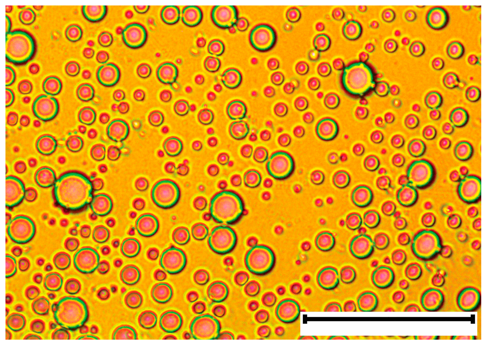
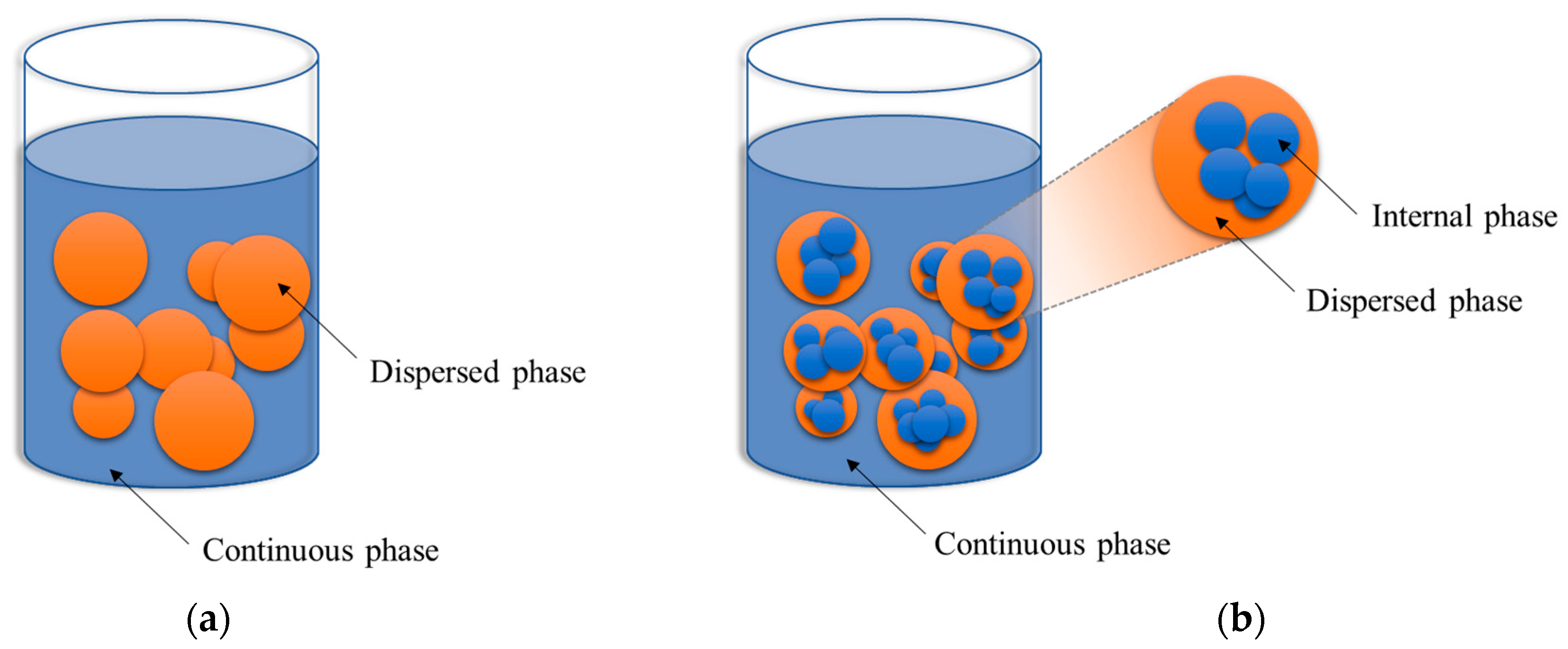
2.1. Fuel-Water Emulsion Characteristics

An emulsion is a mixture of two or more liquids, one of which is present as microscopic or ultra-microscopic droplets and is distributed over the other. The emulsifying liquids are insoluble in themselves, and to stabilize the mixture, surfactants forming films on the surface of the droplets are used [51]. In cases where the stability of the emulsion is not required, it can be produced immediately before use without the participation of an emulsifier in emulsifying devices that are elements of the fuel system [52,53]. In the applications covered by this article, an emulsion includes a fuel such as Jet-A or Biodiesel, water and an optional emulsifier. Figure 1 shows a microscopic image of an exemplary emulsion.
Emulsions can be divided into types based on the number of phases they contain (Figure 2). The two-phase emulsion is characterized by liquid droplets (discrete phase) located in the second liquid, which is a continuous phase (Figure 2a). On the other hand, three-phase emulsions contain an additional phase, which are liquid droplets trapped inside the discrete phase droplets (Figure 2b). Both types of emulsions can also be divided according to what constitutes the continuous phase of the mixture. In water-in-oil emulsions, the fuel is the continuous phase while the water is the dispersed phase, and the opposite is in the case of oil-in-water emulsions. Analogously, in an oil-in-water-in-oil emulsion the continuous phase is fuel, the dispersed phase is water and the internal phase is oil droplets trapped in the aqueous discrete phase. In water-in-oil-in-water emulsions the continuous phase is water, the dispersed phase is oil and the internal phase is water [54].
In order to create a stable emulsion, it is necessary to mix its components [55]. The most commonly used methods of mixing the components of emulsions, in which the stability of the emulsion is increased by the use of an emulsifier, are methods using ultrasonic mixers and various types of mechanical mixers [52]. The mixing time and the power applied to the mixture play a key role in the mixing process. As the mixing power increases, the gradient of the reduction of discrete phase droplets increases over time. Regardless of the mixing power, the drops reach a certain minimum. However, the higher the mixing power is, the faster discrete phase droplets achieve minimum size [56]. Moreover, increasing the mixing power translates into an increase in the stability of the emulsion [57]. This is because increasing the mixing power or its time causes a greater fragmentation of the discrete phase droplets (up to a certain limit). The emulsions with smaller discrete phase droplets are characterized by greater stability [58].
In addition to the previously mentioned factors affecting the stability of the emulsion, its composition is also important. In emulsions consisting of fuel, water and an emulsifier, the proportion of all components is important from the stability point of view. As the water content in the emulsion increases, its stability decreases [57]. The selection of the optimal amount of surfactant is more complex and is described in more detail in Section 2.2.

2.2. Surfactant

Water and fuel (e.g., Jet-A1, diesel fuel) do not mix due to the fact that water is a polar liquid and hydrocarbon liquids are non-polar. Mechanical mixing of the two liquids, polar and non-polar, destroys the surface tension between them, which breaks the dispersed phase into small droplets. Regardless of the amount of energy put into the mixing process, the drops of the dispersed phase will tend to combine and separate from the continuous phase. In order to increase the stability of the mixture of polar and non-polar liquids, emulsifiers are used. Emulsifiers reduce the thermodynamic instability of emulsions, reduce the surface tension between liquids and limit the growth of interfacial free energy. The use of a surfactant leads to an increase in the separation time of the liquid. Moreover, the reduction of the surface tension caused by the addition of an emulsifier enables the use of less external force to complete the emulsification process [55,59,60].
Figure 3a shows the mixture of demineralized water and Jet-A1 aviation fuel. The separation of the two liquids is visible. On the other hand, Figure 3b shows an analogous mixture with the difference that 2% (by weight) of the emulsifier was added to the fuel before applying the water. The fuel with the emulsifier was mixed for 5 min using a mechanical agitator before adding water. In both cases, no mixing was performed after the addition of water. Due to the presence of the surfactant, the water has formed large droplets with fuel in between. A further mixing process would break these droplets until a stable FWE was formed with evenly distributed microscopic water droplets in a continuous phase.
One of the most important parameters of the emulsifier is the Hydrophilic-Lipophilic Balance (HLB). The concept of using HLB for the classification and selection of non-ionic emulsifiers for the first time was proposed in 1948 [61]. In 1954, Griffin numerically defined HLB as [62]:
HLB = 20 × M h / M
where:
M h —molecular mass of the hydrophilic portion of the molecule
M—molecular mass of the whole molecule.
In 1957, Davies proposed an alternative definition based on the chemical groups of the molecule [63]:
HLB = 7 + i = 1 m H i n × 0.475
where:
m—number of hydrophilic groups in the molecule
H i —value of the ith hydrophilic groups
n—number of lipophilic groups in the molecule.
Regardless of the HLB calculation method, low HLB values are attributed to lipophilic emulsifiers and high to hydrophilic surfactants. Therefore, water-in-oil emulsions are made using emulsifiers with an HLB ranging from 3 to 8, while oil-in-water emulsions are made using an emulsifier with an HLB of 9 to 12. To create a stable emulsion, an emulsifier, or a combination of emulsifiers, with an appropriate HLB for a given fuel should be selected [64].
The HLB for an emulsifier that is a mixture of surfactants can be calculated according to the formula [60,65]:
HLB = HLB i × f i
where:
HLB i —HLB value of the ith component of the mixture
f i —mass fraction of the ith component of the mixture.
It should also be noted that the emulsion stability is influenced not only by the HLB of the emulsifier but also by its chemical type [64,66]. In [66], the influence of the type and quantity of emulsifier on the stability of water-in-oil emulsions was investigated. The test was performed with a conventional emulsifier and a gemini type emulsifier. Gemini emulsifiers are characterized by having a long hydrocarbon chain, an ionic group, a spacer, a second ionic group and another hydrocarbon tail, while a conventional emulsifier has a single hydrophobic tail connected to an ionic or polar head [67]. In [66], it was shown that there is an optimal amount of emulsifier to obtain an emulsion with maximum stability. Moreover, for each of the investigated types of emulsifiers, the optimal content differed.

2.3. Combustion Process of the Emulsified Fuel

The combustion of fuel in which microscopic water droplets are dispersed may be accompanied by phenomena of additional droplet atomization, called micro-explosion and puffing [68,69,70,71,72,73,74,75,76,77]. The phenomenon of micro-explosion, which was first described in 1965 [75], is particularly desirable in the process of burning emulsions because it leads to rapid re-atomization of droplets. This translates into an increase in the fuel evaporation surface and additional turbulence in the combustible mixture formation zone.
The phenomenon of micro-explosion may occur due to the fact that emulsion fuels consist of at least two components characterized by different volatility [70,74] which do not mix at the molecular level. Water has a much lower boiling point than liquid hydrocarbon fuels. The phenomenon of micro-explosion occurs when the water inside the emulsion droplet, being overheated, starts to evaporate [70,74,78,79]. The superheated liquid is in a thermodynamically metastable state and is kept there as long as nucleation does not take place [70]. Vapor bubbles form inside the droplet as a result of the rapid nucleation of water inside the droplet, which leads to a micro-explosion. The droplet is re-atomized as a result of the micro-explosion [70,74,78,79].
The second phenomenon related to re-atomization of emulsion droplets is puffing. This is a more local phenomenon than a micro-explosion in which only part of the liquid separates from the main emulsion droplet. The detachment of a water droplet from the parent droplet, due to puffing, can take place in one or two stages. The number of stages depends on the mechanism by which the phenomenon occurs. These are the oscillation of the discrete phase droplet shape, the thrust generated by steam from boiling water and the pulling effects caused by the inertia of the bursting bubble. The influence of a particular mechanism on the course of the process depends on the size of the water droplets in the emulsion [77].
Not every drop of emulsion fuel, when it is heated to the right temperature, causes a micro-explosion. In [74], the influence of the internal parameters of emulsions on their stability and the frequency of micro-explosions were investigated. The research was carried out on single droplets of water-in-oil emulsion in the combustion chamber. Research has shown that the stability of the emulsion has an influence on the frequency of the micro-explosion phenomenon. Less stable emulsions are more prone to this phenomenon. This is because the micro-explosion is favored by the coalescence of water in the dispersed phase. Reducing the emulsion stability increases the likelihood of micro-explosions because water in unstable emulsions coalesces more easily. In emulsions with a very fine distribution of water droplets, coalescence is also difficult, which results in the dominance of creaming, and consequently, the micro-explosion is less effective [80]. Separation of the emulsion phases before the occurrence of the micro-explosion phenomenon is also observed in oil-in-water emulsions [81]. In [79], the properties of the droplet triggering atomization were identified and tested. It has been shown that the atomization quality is influenced by the temperature, the size of water droplets and its position inside the emulsion droplets. Each of the two parameters can be compensated by changing the third.
In [73], the process of ignition and combustion of a single drop of emulsion under transient conditions with the use of a single compression machine was investigated. The continuous phase of the emulsion fuel was n-decane; the dispersed phase was water in the proportions 10%, 20% and 30% (by volume); additionally the mixture contained 2% emulsifier (Sorbitan Monooleate). Based on the conducted research, the droplet combustion process was divided into four successive stages: droplet heating with simultaneous evaporation, classic burning, micro-explosions and emulsifier burning. Burning of the drops proceeding in accordance with the mentioned stages was recorded for the droplets containing 10% and 20% of water, while in the case of emulsions with 30% of water, the burning stage of the emulsifier did not take place. The lack of the emulsifier combustion stage is explained by the increase in the water concentration in the droplet, caused by n-decane combustion, to such an extent that it prevented the surfactant from burning off. It was also noted that as the concentration of water increased, the micro-explosion was more intense. Emulsifier burning as one of the droplet-burning stages was also observed in [72], where n-decane droplets with the addition of nano aluminum particles and an emulsifier (Sorbitan Oleate) were burned. The authors also noted that increasing the amount of emulsifier in the tested mixture, without changing other parameters, led to the extension of the time of this stage.
In order to better understand the combustion and re-atomization processes of emulsion droplets, mathematical models of these phenomena were developed and numerical calculations were performed [77,78,82,83,84,85,86]. One of the models used in the calculations assumes that in the initial phase of heating the emulsion droplets, the discrete phase droplets will evaporate from the outer main volume of the droplet from a depth equal to the diameter of the discrete phase droplet forming an oil membrane (Figure 4) [82,85]. Any remaining water droplets are trapped inside the oil bubble and the formation mechanism depends on the type of emulsion. In [82], using the oil membrane model, a relationship was developed that allows one to calculate the strength of micro-explosions, unified for oil-in-water and water-in-oil emulsions.
According to the described model, there is an optimal water content in the emulsion ensuring the maximum strength of the micro-explosion (Figure 5a). When the water content is too low, the nucleation energy will also be low, leading to a weak micro-explosion. On the other hand, when the amount of water is too large to form an oily membrane, a lot of water will have to evaporate, with the consequence that little water will remain, which will also make the micro-explosion weak. A similar situation occurs in the case of the diameter of the droplets of the dispersed phase in the emulsion, as increasing it leads to an increase in the micro-explosion strength. However, this happens up to a certain limit, as increasing the diameter of the droplets leads to the formation of an oil membrane that is too thick (Figure 5b). Increasing the initial droplet diameter of the emulsion increases the micro-explosion strength (Figure 5c). If the droplet is too small, the micro-explosion will not occur as the oil membrane will not be thick enough.

3. Materials and Methods

The aim of the authors was to obtain all available studies on FWE combustion processes in gas turbines. The exhaust gas emissions were especially analyzed. A total of 23 works were qualified for the final analysis, three of which are articles entirely based on previously prepared publications. In order to avoid an over-representation of results from one laboratory or conducted by one group of researchers, the available publications were grouped into fourteen independent groups.
The literature research was conducted using the Scopus and Web of Science scientific databases, based on keywords, abstracts and titles of scientific papers. In the first step, scientific papers were searched for keywords: “jet engine”, “turbojet engine” and “gas turbine” in conjunction with “emulsion”, “fuel-water emulsion”, “microemulsion”, “fuel water microemulsion” and “water fuel emulsion”. The next step of the selection of scientific articles consisted of the abstract’s analysis, which was positively passed by all preselected papers on emulsion combustion in a gas turbine. In the third step, selection of scientific papers was carried out by analyzing the full text of the paper. Articles focusing on the operational issues of the engine run on FWE without specific description of changes in operating parameters caused by the use of modified fuel were rejected. Literature research was not restricted to specific years.
All data on the content of water and emulsifier in FWE were converted to the content of water in the entire fuel mixture. This was done to standardize the method of determining the amount of water and to facilitate the comparison of the emulsion composition between the analyzed results. The content of the individual components of the FWE, expressed as a volume or mass fraction, remained uncalculated.
Chapter 4 presents the results of a literature analysis of the impact of FWE combustion on NO x and CO emissions as well as smoke in the exhaust gasses.

4. Literature Research

4.1. NOx Emissions

Historically, the oldest publication which shows the influence of emulsion combustion on NO x emissions is the extensive research conducted by the Esso Research and Engineering Company [87] commissioned by the United States Air Force. In these studies, fuel-water emulsions with the mass fraction of water in the mixture—2.47%, 2.53%, 4.18%, 9.09%, 19.06% and 33.33% (13 trials in total)—were tested. It should be noted that the emulsifier Tech Mul-2 was used to produce an emulsion with a mass water content of 2.47%, while the remaining emulsions were made on the basis of an emulsifier which was a mixture of Tween 20 and Span 80. The conclusions of the research indicated that even with the largest mass addition of water (33.33%) no changes in NO x emissions were noted.
A study from 1978 [88] was carried out on the basis of the modified combustion chamber of the Pratt & Whitney FT12 marine turbine. The base fuel was Redwood 650 oil, while the mass content of water in the mixtures was: 4%, 5%, 7.5% and 10%, respectively. No emulsifier was added during preparation of the emulsified fuel. The mixing was accomplished by a high-pressure homogenizer. In the conclusions from the work, it can be read that with a 4% water mass content in the mixture, an increase in NO x emissions was observed compared to pure oil. On the other hand, NO x emissions decreased with increasing water content in the FWE.
In the same year, FWE [46] tests were also carried out on a General Electric J79 full-scale engine with JP-5 base fuel, 2% of emulsifier additive by volume to the base fuel (before the addition of water), being a mixture of SPAN80 and TWEEN80 in the ratio 9:1 and by mass water content in mixing up to 38.2%. The addition of water to the fuel resulted in the reduction of NO x emissions in all tested engine load conditions. The reduction in NO x emissions was greater as more water was contained in the fuel mixture at a given load. For the intermediate load and water content in FWE 25.9%, almost 88% of the NO x emission reduction was achieved compared to the case in which the base fuel was burned.
The research [89], from the same period, on the combustion chamber test stand built out of Allison T-63 engine components shows a significant decrease in NO x emissions. The tests used FWE based on the JP-5 base fuel and the volume fraction of water in the mixture was up to 33.3%, with the volume fraction of the emulsifier in the mixture up to 2%. The emulsifier was a mixture of SPAN80 (90%) and TWEEN80 (10%) with HLB 5.3. Discrete phase droplet sizes ranged from 1 µm to 10 µm. For FWE with a 28.6% by volume water content and a simulated full load, the NO x reduction was 50%.
In [90,91,92], the same test stand was used, this time testing fuel-water emulsions based on the modified (in order to increase the smoke number) base fuels JP-4 and JP-8. The emulsions contained 5% to 20% of water (by volume) together with the Clindrol 100CG emulsifier from Clintwood Chemical Company in amounts equal to the amount of water. As part of the research, fuel with a 10% of Clindrol 100CG (by volume), without the addition of water, was burned as well. It was noted that the NO x emissions in all analyzed cases increased with increasing water content in the FWE. It should be emphasized that in the case of combustion of the mixture of fuel and emulsifier, without the addition of water, NO x emissions increased by as much as 3 times.
The research [93] focused on the analysis of the FWE combustion of fuels with high nitrogen content, i.e., Paraho shale oil, H-Coal © (372–522 K) distillate, No. 2 distillate oil doped with quinoline, H-Coal© (505–616 K) distillate with the mass fraction of nitrogen in its composition of 0.33%, 0.33%, 0.16% and 0.33%, respectively. The Paraho shale oil was supplied by Radian Corporation of Pasadena, California, USA. H-Coal® fuels were supplied by Hydrocarbon Research Inc. in Trenton, NJ, USA. The No. 2 oil used for the base tests as well as the quinoline doped oil was supplied by Exxon. The tests were carried out for the mass ratio of water in the mixture up to 44% ÷ 55%, depending on the base fuel. All nitrogen-containing fuels were characterized by higher levels of NO x emissions, with zero water content compared to No. 2 oil. As a result of the addition of water to the fuel in the form of FWE, an intense decrease in NO x emission to about 23% of the mass content of water in mixing was noted. This tendency occurred for all analyzed cases, but in each of them, a decrease in NO x emissions for the base fuel No. 2 oil was the largest. For No. 2 oil and H-Coal® (372–522K), further increasing of water content in the FWE resulted in a reduction in NO x emissions, but with a lower gradient. However, for base fuels No. 2 oil doped with quinoline and Paraho shale oil, after exceeding 23% by mass of water content in the mixture, the decrease in NO x emission was stopped, and the emission values remained constant. In the case of Coal® base fuel (505–616K), after reaching the minimum emissions for 23% of water (by mass) in the FWE, further increasing the amount of water led to an increase in NO x emissions.
Another trend was obtained on the Allison TF-41 turbojet engine combustion chamber test stand [94,95]. The experiments were carried out for three types of fuel: pure kerosene, water-fuel emulsions with 5% and 10% water and 1% emulsifier added (by volume). The emulsifier was a mixture of two surfactants, SPAN 80 and TWEEN 85, at an amount of 75% and 25%, respectively. The use of FWE resulted in a decrease in NO x emissions. With increasing water content in FWE, the amount of measured nitrogen oxides decreased. The effect was observed in all measurement sections: at the end of the primary zone, at the beginning of the dilution zone and at the exit of the dilution zone.
In [48], the effect of combustion of fuel emulsions with mass water content in the mixing plant up to 50% in the turbine model 9000B, manufactured by Alstom, was investigated. Emulsions were produced directly in the fuel system with the addition of an emulsifier not exceeding 100 ppm. As a result of the tests, a regular and repeated decrease in NO x emissions as a function of water content in the FWE was observed. Feeding the TG, FWE with a mass water content of 33.33% on an 82 MW load resulted in NO x reductions of about 70% compared to the case where pure diesel fuel was burned.
As a result of the research [96] of the can combustion chamber, efforts were made to maintain a constant temperature behind the combustion chamber, equal to 1000 °C, 1100 °C and 1200 °C, respectively. The base fuel was No. 6 oil, and the FWE contained 4.76% and 9.09% of water, respectively (the article does not explicitly specify whether the water content in the mixture was volumetric or bulk). An interesting method of producing fuel emulsions, based on a high-speed homogenizer using ultrasonic waves, was used. NO x emissions increased with increasing temperature behind the combustion chamber and decreased with increasing water content in the FWE compared to the case in which pure base fuel was burned.
A series of tests [50,97,98] aimed at designing a reliable, hybrid combustion chamber for Siemens V84.3A and V94.3A turbines supplied with various liquid fuels: oil No. 2 (heating oil), natural gas condensate and kerosene. The research focused on refining the structure of the injector for multi-fuel operation, although water-fuel mixtures with a water content of up to 50% were burned (the article does not explicitly specify whether the water content in the mixture was volumetric or bulk). The emulsions were produced in the fuel system without the addition of an emulsifier. In the case of both gas turbines (V94.V3 and V84.V3), the use of FWE with the base fuel oil No. 2 and the maximum water content in the emulsion resulted in a significant reduction in NO x emissions. For 115% of the turbine base load, 42 ppm was not exceeded, whereas reference emissions were around 90 ppm for 105% base load. For kerosene and condensate emulsions as the base fuels with the maximum addition of water, in the tests on V84.3A, 42 ppm of NO x emission was not exceeded in the premix mode in the range of 50–100% of the base load [50]. For the V94.3A turbine operating in the premix mode with No. 2 oil as base fuel, an increase in NO x emissions by about 15 ppm was reported as a result of a 10.8% reduction in water content [97,98].
In more recent studies [99] on the stand of a single combustion chamber of the industrial turbine, model MS5002E produced by General Electric Company, in which No. 2 oil with the water content in the mixture reaching 54.5% was used (as in the previous case, the article does not explicitly specify whether the water content in the mixture was by volume or mass), very significant, almost linear, reductions (Figure 6) of NO x were obtained for the turbine design point.
Interesting results were obtained during the tests of the Capstone C60 CHP gas turbine, with a modified injection system adapted to burning liquid fuels and a modified engine controller maintaining a constant temperature (950 K) behind the turbine [47]. The research covered the combustion of pure diesel oil (base variant) and FWE included mixtures of diesel fuel with water in a mass ratio of 25%, 37.5% and 50%. As a result of the research, an increase in NO x emission was obtained in the case of the mass addition of water by 25% and 37.5% in relation to the base variant with a downward trend. With the addition of 50% water, the NO x emissions fell below the baseline.
Research [100,101,102] from the Green Engine Laboratory of the University of Salento in Lecce conducted in 2019–2020, based on the Jet-A1 base fuel with the mass content of water 51.25%, 61%, 67.5% and 68%, 33% also achieved a decrease in NO x emissions with increasing water addition.
The latest research result [49,103,104] of the Polish research team working on miniature turbine engines at the Institute of Heat Engineering of the Warsaw University of Technology bring similar results. FWEs based on the base fuel consisting of a mixture of Jet-A1 with AeroShell Turbine Oil 500 (manufactured by Shell plc) in the mass ratio of 95: 5, 2% mass addition of emulsifier to the fuel and water in the amount of up to 12% of the mass of the mixture were tested. The use of FWE as a fuel resulted in a reduction of NO x emissions, the greater the more water content was present in the emulsified fuel. The maximum notes a NO x emission decrease when burning FWE was more above 35% [49,104] compared to the clean base fuel without the addition of water.

4.2. CO Emissions

Similarly, as in the case of NO x emissions, historically, the oldest studies involving the use of fuel-water emulsions [87] showed no effect of water content in FWE on CO emissions.
In the conclusions from the research [88], one can find information informing that the optimal water mass content in the FWE, using a pressure-atomizing injector, is 4%, when CO emissions reach the minimum level. With the use of air-boost injectors, the CO emission level remained constant, regardless of the water content in the mixture.
In the research [46], it was noticed that for the average turbine load, the water content has little influence on the CO emissions. For 75% of the average load, a significant influence on CO emissions started to be recorded only for 38.2% by mass of water content (maximum tested) in the mixture. At 30% of the average turbine load, an increase in CO emissions at all test points was noted. The results are summarized in Figure 7.
The studies [89] show a clear increase in CO emissions from the test stand with the increase in water content in the FWE.
The increase in CO emissions was also noted in the studies [90,91,92], with a small deviation for the 20% of water (by volume) in the FWE and the maximum load of the turbine when the CO emissions decreased compared to the combustion of the mixture with a 15% water content (by volume).
In the research [93], as a result of water addition to the fuel, CO emissions increased in all analyzed cases, but the values of the observed emissions and the nature of their changes as a function of water quantity in the FWE differed depending on the variant of the oil phase used.
In [94,95], where the concentration of CO was measured in three sections of the combustion chamber, a significantly lower CO concentration was recorded due to the addition of water to the fuel in the first section located at the end of a primary zone. However, in the next two sections, located closer to the outlet from the combustion chamber, the tendency was opposite.
In the study [48], no changes in CO emissions were observed, and their limits for T.A. Luft regulations were not exceeded.
In the study of the can combustor chamber [96], the purpose of which was to maintain a constant temperature behind the combustion chamber, the use of FWE resulted in a reduction of CO emissions. The reduction was more pronounced for the lower temperatures behind the combustion chamber.
In studies [50,97,98], in the case of both turbines manufactured by Siemens (V84.3A and V94.3A), CO emissions did not exceed 10 ppm at the design point and 3 ppm at 70% of the turbine base load.
Very similar results were obtained in [99], where the CO emissions remained below 10 ppm and there was no significant impact of the water content in the FWE on their level.
In the case of a small C60CHP 60 kW turbine from Capstone [47], CO emissions increased with increasing water content in the FWE in the entire tested range. Moreover, it was insensitive to the amount of air flowing through the injector, except for FWE with a 50% mass fraction of water content in the mixture. In this case, increasing the amount of atomizing air resulted in an increase in CO emissions.
The research [100,101,102] shows that 51.25% of water content (by mass) in the mixture causes a slight change in CO emissions compared to the base fuel. In the cases of 61% and 67.5% of water content (by mass) in the FWE, a reduction of CO emissions was observed. For the highest water content in the mixture (68.3% by mass), there was an increase in CO emissions above the level of emissions recorded in the combustion of the base fuel without the addition of water.
In the studies of the miniature gas turbine [49], the emission of CO after the application of FWE decreased in relation to the reference case in the entire range of rotational speeds of the turbine. The decrease in emissions followed the increase in the water content in the emulsion. The maximum noted CO emissions reduction checked slightly over 12%.

4.3. Smoke in the Exhaust Gasses

The first of the described studies, which analyzed the impact of the use of FWE on exhaust gas opacity, were studies of the combustion chamber of the FT12 marine turbine produced by Pratt & Whitney [88]. In the tests, a decrease in the smoke in exhaust gasses was noted. The case of using an emulsion with a minimum smoke emission was achieved for a 4% of water addition (by mass), for which the smoke decreased by 16%.
A study from the same period [46] indicates potential reductions in particulate and smoke emissions due to the FWE combustion. In the case of FWE with 18% water (by mass), the reduction of particulate emissions was 42% up to 0.32 m g m 3 at intermediate load.
Comprehensive studies in terms of smoke emissions [89] have shown that the use of FWE reduces the amount of exhaust smoke for all the tested cases. Based on the nature of the curve showing the degree of smoke in the function of water content, it is concluded that a further increase in the water content in the FWE would result in a further reduction in the smoke; however, this relationship tends asymptotically to a finite value. It has also been reported that the water contained in the emulsion is more effective as a smoke reducer under full load conditions than when running at partial power. In the maximum power regime, the volume content of 13% water reduces smoke emissions by half and increasing the amount of water in the FWE to 23.1% reduces the smoke emissions to the level of one third of the base case emissions. The same is the case for particulate emissions, where the 13% of water content in the FWE leads to a reduction of emissions by about 65%, and the FWE with 23.1% of water by volume, reduces the emissions of solid particles by about 75%, to a value close to 1.0 m g m 3 at full power. The authors also noticed that, for all three kerosene variants tested, the addition of water to the fuel resulted in an equally effective reduction of smoke. It was observed that increasing the content of the emulsifier in the FWE in the tested range reduces the smoke in the exhaust gases. The observation was made for FWE with the content of water in the mixture of 4.8% and 9.1% (by volume). The study of the effect of the droplet size of the discrete phase, which was regulated only by the pressure change in the homogenizer, did not show the dependence between droplet size and smoke emissions.
An extensive description of the effect of water addition to fuel in the form of an emulsion can also be found in [90,91,92]. The use of FWE caused a decrease in smoke in all tested work regimes, compared to the reference case. A decrease was correlated with an increase in water content in the mixture. The exception was the turbine idle load, where, after exceeding 10% of the water volume in the FWE, there was an upward trend for both base fuels (JP-4 & JP-8) noted. For the conditions corresponding to the take-off conditions, there was a reduction in smoke number from 35 to 5 due to the 20% of water content in the fuel.
In the case of the combustion of fuels with high nitrogen content as described in [93], for all variants of the tested FWE, a decrease in smoke was noted along with an increase in water content in the fuel mixture.
In [94,95], a decrease in the soot concentration with an increase in water content in FWE was noted. Measurements were made in the second cross-section (i.e., at the beginning of the dilution zone) and with the base fuel mass flow increased by 32%. For the cases in which pure kerosene and FWE with a 5% volumetric content of water were burned, the peak concentration of soot was recorded in the central combustion zone, while for the FWE with a 10% of water (by volume), the nature of the soot concentration distribution changed. In the central part of the chamber, the soot concentration drop was so intense that its maximum content was located near the combustor chamber walls, where the measured parameter was comparable for all the studied cases.
In studies of the application of FWE to large gas turbines, information can be found that shows the use of FWE has no effect on smoke emissions [48,50,97,98].
Whereas in [96], the use of emulsified fuel resulted in a reduction of particulate matter emissions. This effect was more pronounced for the lower temperatures downstream of the combustion chamber. The reduction of particulate matter by 27% to about 30 m g m 3 was achieved with the temperature behind the combustion chamber equal to 1000 °C. At the same time, it was noticed that the increase in the amount of water in the FWE from 4.76% to 9.09% (the article does not explicitly specify whether the water content in the mixture was volumetric or mass) did not affect significantly particulate matter emissions.

5. Summary of the Literature Research

Tests carried out on gas turbines or test stands of combustion chambers using FWE as fuel were varied in terms of the type of units they were run on, the base fuel, the amount of water in the FWE, the method of producing the emulsion and the optional presence of an emulsifier. This fact makes it difficult to directly compare the results of the research with each other. The list of selected results of the research campaign of individual teams is presented in Table 1 along with the basic parameters of the experiments. This chapter discusses the literature review with particular emphasis on factors that may affect the discrepancies in the results of individual research groups.
In most of the analyzed publications, the addition of water to the fuel in the form of FWE resulted in a reduction of NO x emissions (Table 1). In gas turbines, NO x is produced in four ways: thermal path, rapid formation of NO, formation of nitrogen oxides through formation of N 2 O and formation of nitrogen oxides from fuel nitrogen. The thermal path is dominant, where NO is formed according to the Zeldovich mechanism. The reaction of oxygen with a diatomic nitrogen molecule is characterized by high activation energy, which means that it proceeds intensively at temperatures exceeding 1800 K, and its speed strongly depends on it [42,105,106]. In case of using FWE, the water contained in the fuel, taking energy for evaporation, lowers the temperature within the reaction zone, which translates into a significant decrease in NO x . This cause of NO x reduction is confirmed by the observation of the combustion intensity in the combustion chamber [101,102] and numerical calculations [49,103,104]. Aviation kerosene contains negligible amounts of nitrogen, so the formation of NO x from fuel nitrogen does not affect emissions. In the case of fuels containing nitrogen, the nitrogen contained in the fuel is converted to NO x . The percentage of nitrogen in the fuel that is affected by it depends on the air temperature at the inlet to the combustion chamber and the nitrogen content in the fuel. The lower the temperature and nitrogen content in the fuel, the greater part of it will be converted to NO x [107]. This mechanism can explain the ineffectiveness of NO x reduction in [90,91,92], where the emulsifier added to the FWE in an amount equal to the amount of water contained 4.37% of nitrogen (by mass) in its composition, which translated into an increase in NO x emission along with an increase in water content in the FWE. In [88], where the base fuel was Redwood 650 containing 0.11% by mass of nitrogen in its composition, an increase in NO x emission was also obtained after adding water to the fuel; however, in this case, the course of changes in emissions as a function of water content was more complex. The use of FWE with a mass content of water in the mixture of 4% led to the maximum emissions, and further increasing its amount reduced the NO x emissions. In this case, the NO x emission maximums were correlated with the increase in combustion efficiency, the maximum of which fell on 4–5% of the water content (by mass) in the FWE, depending on the injector used. The computational increase in efficiency is directly correlated with the increase in temperature, which permits the conclusion that the increase in NO x emissions is caused by more intensive NO production according to the thermal Zeldovich mechanism. In the remaining studies analyzing the effect of adding water to FWE with a mass content below 10%, no temperature increase was noted, after FWE application with a content of ~5% water (by mass), which could increase combustion efficiency by 8–15% [49,94,95,104], as was the case in [88]. This suggests that this effect was due to the lack of an optimal combustion chamber design. The test chamber used in [88] was made of elements of the chambers of two engines: FT4 and FT12. As emphasized by the authors of the publication, this leads to the lack of an optimal design of the test stand. In [93], fuels containing 0.16–0.33% nitrogen were burned as base fuel, and yet NO x reduction was achieved after the use of FWE in relation to the case in which only base fuel was burned, but the reduction was much more confusing than for No. 2 oil. Moreover, it was noticed that, with increasing the water content in the FWE, the conversion of nitrogen contained in the fuel to NO x increased. In [96], where No. 6 oil was burned, a reduction in NO x emissions as a result of the use of FWE was achieved, and the reduction was comparable to that recorded in [87]—about 10% on average. Whereas for “nitrogen-free” fuels, about an 18% reduction was obtained for the same amount of water [49,94]. In [47], adding water to diesel fuel increased NO x emissions for emulsions with 25% and 37.5% of water (by mass). Only the application of the emulsion with a 50% of water (by mass) resulted in a decrease in NO x emission in relation to base fuel. However, in [87], the emission of NO x as well as CO and UHC was insensitive to the use of emulsions with the mass fraction of water up to 32.3%. These cases are exceptions that are difficult to interpret.
The effect of using FWE and increasing the water content in mixture on CO emissions is ambiguous. CO emissions in three of the analyzed groups decreased as a result of the application of FWE [49,96,100,101]; in five they remained constant or did not exceed the emission limits for a given unit [49,50,87,88,97,98,99] and in six cases they increased [46,47,89,90,91,92,93,94,95]. There is no clear correlation between the nature of changes in CO emissions as a function of water content in FWE. The emulsifier may influence the CO emission from gas turbines [108], but in the context of Table 1 it does not play a decisive role. In [88], changing the injector in the combustion chamber from the pressure-atomizing nozzle to the air-boost nozzle resulted not only in the change of the CO emission value but also in the change of the nature of the CO emission trend as a function of the water content in the FWE. After changing the injector, the CO emissions remained insensitive to the water content of the fuel, unlike the previous case. This suggests that the impact of the use of FWE on CO emissions is small compared to other aspects such as the design of the combustion chamber assembly and/or the fuel supply method.
The emission of soot/smoke/particulate matter was also reduced as a result of the use of FWE in all of the analyzed studies, except [48,50,97] where it was only mentioned that the limit was not exceeded.
In addition, in the process of research literature analysis it was noted that the consumption of base fuel with the use of FWE in turbojet engines does not increase to the limit of approximately 12–13% of water addition (by mass) and may even lead to a slight reduction in consumption [46,49,104]. The limitations of the fuel system did not allow testing of emulsions with large amounts of water; therefore, it is not certain whether this trend persists for mixtures with more than 13% of water mass content. This means that the increase in total fuel system mass flow is equal to the mass of water and emulsifier added to produce the FWE. In energy gas turbines, the use of FWE does not lead to difficulties in maintaining the output power at a constant flow rate of base fuel [47].
It is worth noting that the use of fuel with the addition of water in the form of FWE leads to changes in the flame structure, which translates into a change in the temperature distribution inside the combustion chamber [49,99,101,102,103,104]. At low water content in FWE (FWE with up to 12% water were tested), the area of high temperature in the combustion chamber stretches while extinguishing hot spots [49,103,104]. In the case of the combustion of FWE with a water content above 50%, a decrease in the visible flame volume and its intensity was noted [101,102]. The change in temperature distribution inside the combustion chamber is also observed on the surface of the combustion chamber walls. Numerical calculations of combustion inside the miniature GTM-120 gas turbine showed an increase in average temperature near the combustion chamber liners of up to 11K while burning the FWE containing up to 12% of water (by mass) in comparison with the base fuel [49]. In [99], a noticeable reduction in temperature at the liner wall in the experiment occurred only after exceeding 37.5% of the water content (unfortunately, the article does not specify whether the quoted water content is related to the mass or volume of the mixture). In the same case, despite the lower temperature of the liner, a slight increase in the temperature of the transition between the combustion chamber and the turbine and an increase in the thermal load of the turbine blades were noted. The area where the heat load was most influenced by the application of the FWE was the cap where the temperature drop was noted. These observations correlate well with [94,95] where, in the measurement section located at the end of a primary zone, a decrease in the measured temperature was noted with an increase in the water content in the FWE (range: up to 10% volumetric water content), in the section located at the beginning of the dilution zone, the temperature was insensitive to the addition of water, while in the section located in the end of dilution zone, the temperature slightly increased with increasing water content in the FWE. It should be added that the temperature changes of the hot section [49,99] were so small that it did not lead to any structural or material changes in the gas turbine.
In many research articles on the FWE combustion in gas turbines and reciprocating engines, it is hypothesized that the phenomenon of micro-explosion contributes to the improvement of the combustion process [47,49,54,109,110]. However, no studies confirming the above thesis were found in the analyzed literature. The intensity of the micro-explosion phenomenon is influenced by the parameters of the atomized fuel droplets, such as their size, the size of the discrete phase droplets and the amount of water in the droplet [82,85]. In research on emulsified fuels, the amount of water in the emulsion is usually used as a variable, which also affects the process of fuel droplets’ evaporation [111]. Based on [89], the change in the size of the discrete phase droplets within the range of 1–10μm (regulated by the pressure drop on the homogenizer valve) does not have a significant effect on the combustion parameters and emissions, apart from CO and UHC emission (Figure 8). It should be noted, however, that these data come from only one sample for each of the three cases studied. The data is presented in dimensionless form with respect to the case where the pressure drop across the homogenizer was the largest, which generated the smallest droplets of the dispersed phase, 1–2 µm.

6. Conclusions

Based on the analysis of the available research on the impact of the use of fuel-water emulsion on operating parameters and emissions from gas turbines, the following conclusions are drawn:
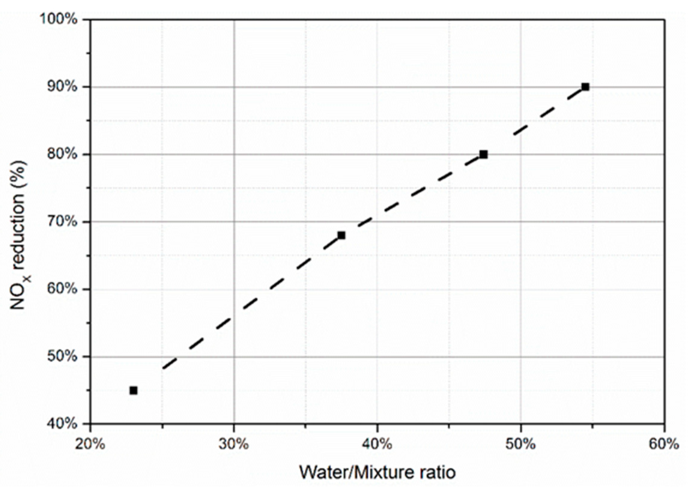
  • The addition of water to the fuel in the form of a fuel-water emulsion effectively reduces NO x emissions in fuel mixtures containing negligible amounts of nitrogen. The reduction is caused by the reduced production of NO according to the Zeldovich mechanism, which occurs as a result of the reduction of the maximum temperature in the reaction area, and it becomes more intense the more water is in the emulsion.
  • Increasing the water content of an emulsion in which the base fuel contains significant amounts of nitrogen reduces the NO x reduction efficiency. This is because the conversion of fuel nitrogen to NO x increases as the amount of water in the emulsion increases.
  • The use of a fuel-water emulsion to supply gas turbines reduces the smoke and particulate matter in the exhaust gasses.
  • The use of fuel-water emulsion has little effect on CO emissions from gas turbines. The reason for the observed increases in emissions in the analyzed studies may be a change in the structure of the reaction zone in the combustion chamber, which may translate into a significantly less optimal course of this process compared to the original design conditions of the combustion chamber.
  • The use of fuel-water emulsion does not cause radical changes in the consumption of the base fuel. The total mass flow of the fuel mixture applied by the gas turbine injectors in the case of using emulsified fuel is approximately equal to the mass flow of the base fuel burned in the reference case, increased by the mass flow of water and (if applicable) the emulsifier contained in the emulsion.
  • In the process of analyzing the available literature, the necessity to analyze the influence of the phenomenon of micro-explosion of fuel-water emulsion droplets on the operating parameters and emission of pollutants from gas turbines was demonstrated.

Author Contributions

Conceptualization, P.N. and M.G.; methodology, P.N.; investigation, P.N.; writing—original draft, P.N. and M.C.; writing—review & editing, M.C. and M.G.; visualization, M.C.; supervision, M.G. All authors have read and agreed to the published version of the manuscript.

Funding

This research received no external funding.

Data Availability Statement

Not applicable.

Conflicts of Interest

The authors declare no conflict of interest.

References

  1. Capuano, D.L. Energy Information Administration; Annual Energy Outlook: Washington, DC, USA, 2020.
  2. Čampara, L.; Hasanspahić, N.; Vujičić, S. Overview of MARPOL ANNEX VI regulations for prevention of air pollution from marine diesel engines. In Proceedings of the GLOBMAR 2018—Global Maritime Conference, SHS Web Conference, Sopot, Poland, 19–20 April 2018; p. 01004. [Google Scholar] [CrossRef]
  3. van Vliet, J.; van den Berg, M.; Schaeffer, M.; van Vuuren, D.P.; Den Elzen, M.; Hof, A.F.; Beltran, A.M.; Meinshausen, M. Copenhagen Accord Pledges imply higher costs for staying below 2 °C warming. Clim. Change 2012, 113, 551–561. [Google Scholar] [CrossRef]
  4. Rhodes, C.J. The 2015 Paris climate change conference: COP21. Sci. Prog. 2016, 99, 97–104. [Google Scholar] [CrossRef] [PubMed]
  5. Anderson, K.; Bows, A. Executing a Scharnow turn: Reconciling shipping emissions with international commitments on climate change. Carbon Manag. 2012, 3, 615–628. [Google Scholar] [CrossRef]
  6. Armellini, A.; Daniotti, S.; Pinamonti, P.; Reini, M. Evaluation of gas turbines as alternative energy production systems for a large cruise ship to meet new maritime regulations. Appl. Energy 2018, 211, 306–317. [Google Scholar] [CrossRef] [Green Version]
  7. El-Gohary, M.M. The future of natural gas as a fuel in marine gas turbine for LNG carriers. Proc. Inst. Mech. Eng. Part M J. Eng. Marit. Environ. 2012, 226, 371–377. [Google Scholar] [CrossRef]
  8. Ammar, N.R.; Farag, A.I. CFD modeling of syngas combustion and emissions for marine gas turbine applications. Pol. Marit. Res. 2016, 3, 39–49. [Google Scholar] [CrossRef] [Green Version]
  9. Arai, M.; Sugimoto, T.; Imai, K.; Miyaji, H.; Nakanishi, K.; Hamachi, Y. Research and development of gas turbine for next-generation marine propulsion system (super marine gas turbine). In Proceedings of the International Gas Turbine Congress, Tokyo, Japan, 2–7 November 2003. [Google Scholar]
  10. Cames, M.; Graichen, J.; Pulles, H. Issues at Stake at the 10th Session of the ICAO Committee on Avitaion Environmental Protection (CAEP/10); Technical Report; European Parlament (EU): Strasbourg, France, 2016. [Google Scholar]
  11. National Aeronautics and Space Administration. Types of Gas Turbines. Available online: https://www.grc.nasa.gov/www/k-12/airplane/trbtyp.html (accessed on 17 July 2022).
  12. Owen, B.; Lee, D.S.; Lim, L. Flying into the future: Aviation emissions scenarios to 2050. Environ. Sci. Technol. 2010, 44, 2255–2260. [Google Scholar] [CrossRef] [PubMed]
  13. Ranasinghe, K.; Guan, K.; Gardi, A.; Sabatini, R. Review of advanced low-emission technologies for sustainable aviation. Energy 2019, 188, 115945. [Google Scholar] [CrossRef]
  14. Mercer, C.; Haller, W.; Tong, M. Adaptive engine technologies for aviation CO2 emissions reduction. In Proceedings of the 42nd AIAA/ASME/SAE/ASEE Joint Propulsion Conference & Exhibit, Sacramento, CA, USA, 9–12 July 2006. [Google Scholar] [CrossRef]
  15. Fulara, S.; Chmielewski, M.; Gieras, M. Variable Geometry in Miniature Gas Turbine for Improved Performance and Reduced Environmental Impact. Energies 2020, 13, 5230. [Google Scholar] [CrossRef]
  16. Liu, Y.; Sun, X.; Sethi, V.; Nalianda, D.; Li, Y.G.L.; Wang, L. Review of modern low emissions combustion technologies for aero gas turbine engines. Prog. Aerosp. Sci. 2017, 94, 12–45. [Google Scholar] [CrossRef] [Green Version]
  17. Devi, P.B.; Joseph, D.R.; Gokulnath, R.; Manigandan, S.; Gunasekar, P.; Anand, T.P.; Venkatesh, S.; Vimal, R.M. The effect of TiO2 on engine emissions for gas turbine engine fueled with jatropha, butanol, soya and rapeseed oil. Int. J. Turbo Jet Engines 2020, 37, 85–94. [Google Scholar] [CrossRef]
  18. Chmielewski, M.; Gieras, M. Impact of variable geometry combustor on performance and emissions from miniature gas turbine engine. J. Energy Inst. 2017, 90, 257–264. [Google Scholar] [CrossRef]
  19. Renyu, F.; Man, Z. Low emission commercial aircraft engine combustor development in China: From airworthiness requirements to combustor design. Procedia Eng. 2011, 17, 618–626. [Google Scholar] [CrossRef] [Green Version]
  20. Stathopoulos, P.; Paschereit, C.O. Retrofitting micro gas turbines for wet operation. A way to increase operational flexibility in distributed CHP plants. Appl. Energy 2015, 154, 438–446. [Google Scholar] [CrossRef]
  21. Klimenko, V.V.; Klimenko, A.V.; Kasilova, E.V.; Rekunenko, E.S.; Tereshin, A.G. Performance of gas turbines in Russia under the changing climatic conditions. Therm. Eng. 2016, 63, 690–698. [Google Scholar] [CrossRef]
  22. Wołowicz, M.; Kolasiński, P.; Badyda, K. Modern Small and Microcogeneration Systems—A Review. Energies 2021, 14, 785. [Google Scholar] [CrossRef]
  23. Harun, N.F.; Tucker, D.; Adams II, T.A. Technical challenges in operating an SOFC in fuel flexible gas turbine hybrid systems: Coupling effects of cathode air mass flow. Appl. Energy 2017, 190, 852–867. [Google Scholar] [CrossRef] [Green Version]
  24. Harutyunyan, A.; Badyda, K.; Wołowicz, M.; Milewski, J. Gas turbine selection for hot windbox repowering on 200 MW fossil fuel power plant. J. Power Technol. 2019, 99, 142. [Google Scholar]
  25. Jonsson, M.; Yan, J. Humidified gas turbines—a review of proposed and implemented cycles. Energy 2005, 30, 1013–1078. [Google Scholar] [CrossRef]
  26. Moschini, G.; Cui, J.; Lapan, H. Economics of biofuels: An overview of policies, impacts and prospects. Bio Based Appl. Econ. 2012, 1, 269–296. [Google Scholar]
  27. Caspeta, L.; Buijs, N.A.; Nielsen, J. The role of biofuels in the future energy supply. Energy Environ. Sci. 2013, 6, 1077–1082. [Google Scholar] [CrossRef] [Green Version]
  28. Rochelle, D.; Najafi, H. A review of the effect of biodiesel on gas turbine emissions and performance. Renew Sustain. Energy Rev. 2019, 105, 129–137. [Google Scholar] [CrossRef]
  29. Gökalp, I.; Lebas, E. Alternative fuels for industrial gas turbines (AFTUR). Appl. Therm. Eng. 2004, 24, 1655–1663. [Google Scholar] [CrossRef]
  30. Starik, A.M.; Savel’ev, A.M.; Favorskii, O.N.; Titova, N.S. Analysis of emission characteristics of gas turbine engines with some alternative fuels. Int. J. Green Energy 2018, 15, 161–168. [Google Scholar] [CrossRef]
  31. Blakey, S.; Rye, L.; Wilson, C.W. Aviation gas turbine alternative fuels: A review. Proc. Combust. Inst. 2011, 33, 2863–2885. [Google Scholar] [CrossRef]
  32. Gupta, K.K.; Rehman, A.; Sarviya, R.M. Bio-fuels for the gas turbine: A review. Renew Sustain. Energy Rev. 2010, 14, 2946–2955. [Google Scholar] [CrossRef]
  33. Talero, G.; Bayona-Roa, C.; Muñoz, G.; Galindo, M.; Silva, V.; Pava, J.; Lopez, M. Experimental methodology and facility for the J69-engine performance and emissions evaluation using jet A1 and biodiesel blends. Energies 2019, 12, 4530. [Google Scholar] [CrossRef] [Green Version]
  34. Chapman, A.; Itaoka, K.; Hirose, K.; Davidson, F.T.; Nagasawa, K.; Lloyd, A.C.; Webber, M.E.; Kurban, Z.; Managi, S.; Tamaki, T.; et al. A review of four case studies assessing the potential for hydrogen penetration of the future energy system. Int. J. Hydrogen Energy 2019, 44, 6371–6382. [Google Scholar] [CrossRef]
  35. Juknelevicius, R.; Szwaja, S.; Pyrc, M.; Gruca, M. Influence of hydrogen co-combustion with diesel fuel on performance, smoke and combustion phases in the compression ignition engine. Int. J. Hydrogen Energy 2019, 44, 19026–19034. [Google Scholar] [CrossRef]
  36. Wang, S.; Ji, C.; Zhang, B.; Zhou, X. Analysis on combustion of a hydrogen-blended gasoline engine at high loads and lean conditions. Energy Procedia 2014, 61, 323–326. [Google Scholar] [CrossRef]
  37. Chiesa, P.; Lozza, G.; Mazzocchi, L. Using hydrogen as gas turbine fuel. J. Eng. Gas Turbines Power 2005, 127, 73–80. [Google Scholar] [CrossRef]
  38. Ayed, A.H.; Kusterer, K.; Funke, H.W.; Keinz, J.; Bohn, D. CFD based exploration of the dry-low-NOx hydrogen micromix combustion technology at increased energy densities. Propuls. Power Res. 2017, 6, 15–24. [Google Scholar] [CrossRef]
  39. Chiong, M.C.; Chong, C.T.; Ng, J.H.; Mashruk, S.; Chong, W.W.F.; Samiran, N.A.; Mong, G.R.; Valera-Medina, A. Advancements of combustion technologies in the ammonia-fuelled engines. Energy Convers. Manag. 2021, 244, 114460. [Google Scholar] [CrossRef]
  40. Munawer, M.E. Human health and environmental impacts of coal combustion and post-combustion wastes. J. Sustain. Min. 2018, 17, 87–96. [Google Scholar] [CrossRef]
  41. Jonson, J.E.; Borken-Kleefeld, J.; Simpson, D.; Nyíri, A.; Posch, M.; Heyes, C. Impact of excess NOx emissions from diesel cars on air quality, public health and eutrophication in Europe. Environ. Res. Lett. 2017, 12, 094017. [Google Scholar] [CrossRef] [Green Version]
  42. Łapucha, R. Komory Spalania Silników Turbinowo-Odrzutowych: Procesy, Obliczenia, Badania, 1st ed.; Wydawnictwa Naukowe Instytutu Lotnictwa: Warsaw, Poland, 2004; pp. 128–143.
  43. Pavri, R.; Moore, G.D. Gas Turbine Emissions and Control; GE Energy Services: Atlanta, GA, USA, 2001. [Google Scholar]
  44. Gieras, M. Komory Spalania Silników Turbinowych: Organizacja Procesu Spalania, 1st ed.; Oficyna Wydawnicza Politechniki Warszawskiej: Warsaw, Poland, 2010; pp. 124–132. [Google Scholar]
  45. Yan, J.; Ji, X.; Jonsson, M. Thermodynamic property models for the simulation of advanced wet cycles. In Proceedings of the 2003 International Joint Power Generation Conference, Atlanta, GA, USA, 16–19 June 2003; Volume 3686, pp. 211–219. [Google Scholar] [CrossRef]
  46. Klarman, A.F.; Rollo, A.J.; Scott, H.C. Evaluation of the Water/Fuel Emulsion Concept for Test Cell Smoke Abatement; Naval Air Propulsion Center, Propulsion Technology and Project Engineering Dept: Trenton, NJ, USA, 1978. [Google Scholar]
  47. Aguilar Hernandez, D.; Sullivan-Lewis, E.; McDonell, V. Adaptation of a 60kW Commercial Natural Gas Fired Microturbine for Operation on Diesel and Diesel-Water Emulsions. In Proceedings of the ASME Turbo Expo 2017: Turbomachinery Technical Conference and Exposition, Charlotte, NC, USA, 26–30 June 2017; Volume 50848, p. V04AT04A053. [Google Scholar] [CrossRef]
  48. Molière, M.; Colas, M.; Freimark, M. Des émulsions eau-fuel pour réduire les émissions de NOx de turbines à gaz. Rev. Gén. Therm. 1989, 330–331, 428–435. [Google Scholar]
  49. Niszczota, P.; Gieras, M. Impact of the Application of Fuel and Water Emulsion on CO and NOx Emission and Fuel Consumption in a Miniature Gas Turbine. Energies 2021, 14, 2224. [Google Scholar] [CrossRef]
  50. Meisl, J.; Lauer, G.; Hoffmann, S. Low NOx emission technology for the VX4. 3A gas turbine series in fuel oil operation. In Proceedings of the ASME Turbo Expo 2002: Power for Land, Sea, and Air, Amsterdam, The Netherlands, 3–6 June 2002; Volume 36061, pp. 665–671. [Google Scholar] [CrossRef]
  51. Encyclopedia Britannica. Available online: https://www.britannica.com/science/emulsion-chemistry (accessed on 14 September 2021).
  52. Sartomo, A.; Santoso, B.; Muraza, O. Recent progress on mixing technology for water-emulsion fuel: A review. Energy Convers. Manag. 2020, 213, 112817. [Google Scholar] [CrossRef]
  53. Basilicata, C.; Cerri, G.; Chennaoui, L.; Giovannelli, A.; Miglioli, M. Dynamics of a Prescribed Mixing Ratio Variable Fuel Flow Valve. In Proceedings of the ASME Turbo Expo 2010: Power for Land, Sea, and Air, Glasgow, UK, 14–18 June 2010; Volume 43963, pp. 527–536. [Google Scholar] [CrossRef]
  54. Yahaya Khan, M.; Abdul Karim, Z.A.; Hagos, F.Y.; Aziz, A.R.A.; Tan, I.M. Current Trends in Water-in-Diesel Emulsion as a Fuel. Sci. World J. 2014, 2014, 527472. [Google Scholar] [CrossRef] [PubMed] [Green Version]
  55. Chen, G.; Tao, D. An experimental study of stability of oil–water emulsion. Fuel Process. Technol. 2005, 86, 499–508. [Google Scholar] [CrossRef]
  56. Cucheval, A.; Chow, R.C.Y. A study on the emulsification of oil by power ultrasound. Ultrason. Sonochemistry 2008, 15, 916–920. [Google Scholar] [CrossRef] [PubMed]
  57. Ghannam, M.T.; Selim, M.Y. Stability behavior of water-in-diesel fuel emulsion. Pet. Sci. Technol. 2009, 27, 396–411. [Google Scholar] [CrossRef]
  58. Patil, H.; Gadhave, A.; Mane, S.; Waghmare, J. Analyzing the stability of the water-in-diesel fuel emulsion. J. Dispers. Sci. Technol. 2015, 36, 1221–1227. [Google Scholar] [CrossRef]
  59. Lin, C.Y.; Chen, L.W. Comparison of fuel properties and emission characteristics of two-and three-phase emulsions prepared by ultrasonically vibrating and mechanically homogenizing emulsification methods. Fuel 2008, 87, 2154–2161. [Google Scholar] [CrossRef]
  60. Mondal, P.K.; Mandal, B.K. Experimental investigation on the combustion, performance and emission characteristics of a diesel engine using water emulsified diesel prepared by ultrasonication. J. Braz. Soc. Mech. Sci. Eng. 2018, 40, 1–17. [Google Scholar] [CrossRef]
  61. Pasquali, R.C.; Sacco, N.; Bregni, C. The studies on hydrophilic-lipophilic balance (HLB): Sixty years after William C. Griffin’s pioneer work (1949-2009). Lat. Am. J. Pharm. 2009, 28, 313–317. [Google Scholar]
  62. Griffin, W.C. Classification of surface-active agents by “HLB”. J. Soc. Cosmet. Chem. 1949, 1, 311–326. [Google Scholar]
  63. Davies, J.T. A quantitative kinetic theory of emulsion type, I. Physical chemistry of the emulsifying agent. In Proceedings of the International Congress of Surface Activity, London, England, January 1957. [Google Scholar]
  64. Schmidts, T.; Dobler, D.; Guldan, A.C.; Paulus, N.; Runkel, F. Multiple W/O/W emulsions—Using the required HLB for emulsifier evaluation. Colloids Surf. A Physicochem. Eng. Asp. 2010, 372, 48–54. [Google Scholar] [CrossRef]
  65. Pasquali, R.C.; Taurozzi, M.P.; Bregni, C. Some considerations about the hydrophilic–lipophilic balance system. Int. J. Pharm. 2008, 356, 44–51. [Google Scholar] [CrossRef] [PubMed]
  66. Nadeem, M.; Rangkuti, C.; Anuar, K.; Haq, M.R.U.; Tan, I.B.; Shah, S.S. Diesel engine performance and emission evaluation using emulsified fuels stabilized by conventional and gemini surfactants. Fuel 2006, 85, 2111–2119. [Google Scholar] [CrossRef]
  67. Hait, S.K.; Moulik, S.P. Gemini surfactants: A distinct class of self-assembling molecules. Curr. Sci. Bangalore 2002, 82, 1101–1111. [Google Scholar]
  68. Watanabe, H.; Suzuki, Y.; Harada, T.; Matsushita, Y.; Aoki, H.; Miura, T. An experimental investigation of the breakup characteristics of secondary atomization of emulsified fuel droplet. Energy 2010, 35, 806–813. [Google Scholar] [CrossRef]
  69. Rao, D.C.K.; Karmakar, S.; Som, S.K. Puffing and micro-explosion behavior in combustion of butanol/Jet A-1 and acetone-butanol-ethanol (ABE)/Jet A-1 fuel droplets. Combust. Sci. Technol. 2017, 189, 1796–1812. [Google Scholar] [CrossRef] [Green Version]
  70. Kadota, T.; Yamasaki, H. Recent advances in the combustion of water fuel emulsion. Prog. Energy Combust. Sci. 2002, 28, 385–404. [Google Scholar] [CrossRef]
  71. Jeong, I.; Lee, K.H.; Kim, J. Characteristics of auto-ignition and micro-explosion behavior of a single droplet of water-in-fuel. J. Mech. Sci. Technol. 2008, 22, 148–156. [Google Scholar] [CrossRef]
  72. Gan, Y.; Qiao, L. Combustion characteristics of fuel droplets with addition of nano and micron-sized aluminum particles. Combust. Flame 2011, 158, 354–368. [Google Scholar] [CrossRef]
  73. Kim, H.; Baek, S.W. Combustion of a single emulsion fuel droplet in a rapid compression machine. Energy 2016, 106, 422–430. [Google Scholar] [CrossRef]
  74. Califano, V.; Calabria, R.; Massoli, P. Experimental evaluation of the effect of emulsion stability on micro-explosion phenomena for water-in-oil emulsions. Fuel 2014, 117, 87–94. [Google Scholar] [CrossRef]
  75. Ivanov, V.M.; Nefedov, P.I. Experimental Investigation of the Combustion Process of Natural and Emulsified Liquid Fuels; National Aeronautics and Space Administration: Washington, DC, USA, 1965.
  76. Antonov, D.V.; Strizhak, P.A.; Fedorenko, R.M.; Nissar, Z.; Sazhin, S.S. Puffing/micro-explosion in rapeseed oil/water droplets: The effects of coal micro-particles in water. Fuel 2021, 289, 119814. [Google Scholar] [CrossRef]
  77. Shinjo, J.; Xia, J.; Ganippa, L.C.; Megaritis, A. Physics of puffing and microexplosion of emulsion fuel droplets. Phys. Fluids 2014, 26, 103302. [Google Scholar] [CrossRef]
  78. Rodzewicz, R.; Gieras, M. Numerical investigation of heat transfer in fuel-water emulsion droplet. Arch. Combust. 2018, 38, 1–10. [Google Scholar]
  79. Moussa, O.; Tarlet, D.; Massoli, P.; Bellettre, J. Investigation on the conditions leading to the micro-explosion of emulsified fuel droplet using two colors LIF method. Exp. Therm. Fluid Sci. 2020, 116, 110106. [Google Scholar] [CrossRef]
  80. Mura, E.; Massoli, P.; Josset, C.; Loubar, K.; Bellettre, J. Study of the micro-explosion temperature of water in oil emulsion droplets during the Leidenfrost effect. Exp. Therm. Fluid. Sci. 2012, 43, 63–70. [Google Scholar] [CrossRef]
  81. Segawa, D.; Yamasaki, H.; Kadota, T.; Tanaka, H.; Enomoto, H.; Tsue, M. Water-coalescence in an oil-in-water emulsion droplet burning under microgravity. Proc. Combust. Inst. 2000, 28, 985–990. [Google Scholar] [CrossRef]
  82. Fu, W.B.; Hou, L.Y.; Wang, L.; Ma, F.H. A unified model for the micro-explosion of emulsified droplets of oil and water. Fuel Process. Technol. 2002, 79, 107–119. [Google Scholar] [CrossRef]
  83. Nissar, Z.; Rybdylova, O.; Sazhin, S.S.; Heikal, M.; Aziz, A.R.B.; Ismael, M.A. A model for puffing/microexplosions in water/fuel emulsion droplets. Int. J. Heat Mass Transf. 2020, 149, 119208. [Google Scholar] [CrossRef]
  84. Sazhin, S.S.; Rybdylova, O.; Crua, C.; Heikal, M.; Ismael, M.A.; Nissar, Z.; Aziz, A.R.B. A simple model for puffing/micro-explosions in water-fuel emulsion droplets. Int. J. Heat. Mass Transf. 2019, 131, 815–821. [Google Scholar] [CrossRef]
  85. Le Clercq, P.; Noll, B.; Aigner, M. Modeling evaporation and microexplosion of water-in-alkane emulsion droplets. In Proceedings of the AIChE 2006 Annual Meeting, San Francisco, CA, USA, 12–17 November 2006. [Google Scholar]
  86. Fostiropoulos, S.; Strotos, G.; Nikolopoulos, N.; Gavaises, M. Numerical investigation of heavy fuel oil droplet breakup enhancement with water emulsions. Fuel 2020, 278, 118381. [Google Scholar] [CrossRef]
  87. Shaw, H. Fuel Modification for Abatement of Aircraft Turbine Engine Oxides of Nitrogen Emissions; Esso Research and Engineering Co. Linden NJ Government Research Lab.: Linden, NJ, USA, 1972. [Google Scholar]
  88. Spadaccini, L.J.; Pelmas, J. Evaluation of oil/water emulsions for gas turbine engines. Adv. Chem. 1978, 166, 232–244. [Google Scholar] [CrossRef]
  89. Moses, C.A.; Coon, C.W.; Altavilla, P.A. Reduction of Exhaust Smoke from Gas-Turbine Engines by Using Fuel Emulsions; Army Fuels and Lubricants Research Lab, Southwest Research Institute: San Antonio, TX, USA, 1980. [Google Scholar]
  90. Naegeli, D.W.; Moses, C.A. Fuel microemulsions for jet engine smoke reduction. J. Eng. Power 1983, 105, 18–23. [Google Scholar] [CrossRef]
  91. Naegeli, D.W.; Moses, C.A. Fuel Microemulsions for Jet Engine Smoke Reduction. In Proceedings of the ASME 1982 International Gas Turbine Conference and Exhibit, London, England, 18–22 April 1982; Volume 79580, p. V003T06A009. [Google Scholar] [CrossRef]
  92. Naegeli, D.W.; Fodor, G.E.; Moses, C.A. Fuel Microemulsions for Jet Engine Smoke Reduction; Tyndall Air Force Base: Panama City, FL, USA, 1980. [Google Scholar]
  93. Singh, P.P.; Mulik, P.R.; Cohn, C. Effect of Using Emulsions of High Nitrogen Containing Fuels and Water in a Gas Turbine Combustor on NOx and Other Emissions. In Proceedings of the ASME 1982 International Gas Turbine Conference and Exhibit, London, England, 18–22 April 1982; Volume 79580, p. V003T06A031. [Google Scholar] [CrossRef] [Green Version]
  94. Zhang, Z.; Gollahalli, S.R. Combustion of Kerosene-Water Emulsions in a Gas Turbine Combustor. In Proceedings of the ASME 1985 Beijing International Gas Turbine Symposium and Exposition, Beijing, China, 1–7 September 1985; Volume 79436, p. V002T04A030. [Google Scholar] [CrossRef] [Green Version]
  95. Zhang, Z.; Gollahalli, S.R. Combustion of Kerosene-Water Emulsions in a Gas Turbine Combustor. Int. J. Turbo Jet Engines 1988, 5, 39–50. [Google Scholar] [CrossRef]
  96. Lee, T.S.; Yang, J.Y. An Experimental Study on the Burning of Water-in-Ol Emulsions. Trans. Aeronaut Astronaut Soc. China 1999, 31, 252–277. [Google Scholar]
  97. Prade, B.; Meisl, J.R.; Berenbrink, P.; Streb, H.; Hoffmann, S. Burner development for flexible engine operation of the newest Siemens gas turbines. In Proceedings of the ASME Turbo Expo 2003, collocated with the 2003 International Joint Power Generation Conference, Atlanta, GA, USA, 16–19 June 2003; Volume 36851, pp. 371–376. [Google Scholar] [CrossRef]
  98. Lauer, G.; Meisl, J.; Belting, C.; Hoffmann, S. Further development of low-emissions oil combustion in the Vx4. 3A hybrid burner. VGB Powertech. 2002, 82, 51–55. [Google Scholar]
  99. Zucca, A.; Khayrulin, S.; Vyazemskaya, N.; Shershnyov, B.; Myers, G. Development of a liquid fuel system for GE MS5002E gas turbine: Rig test validation of the combustor performance. In Proceedings of the ASME Turbo Expo 2014: Turbine Technical Conference and Exposition, Düsseldorf, Germany, 16–20 June 2014; Volume 4569, p. V04BT04A007. [Google Scholar] [CrossRef]
  100. De Giorgi, M.G.; Ciccarella, G.; Ficarella, A.; Fontanarosa, D.; Pescini, E. Effect of jet-A1 emulsified fuel on aero-engine performance and emissions. In Proceedings of the International Conference on Multifunctional Materials (ICMM-2019), Hyderabad, India, 19–21 December 2019. [Google Scholar] [CrossRef]
  101. De Giorgi, M.G.; Fontanarosa, D.; Ficarella, A.; Pescini, E. Effects on performance, combustion and pollutants of water emulsified fuel in an aeroengine combustor. Appl. Energy 2020, 260, 114263. [Google Scholar] [CrossRef]
  102. De Giorgi, M.G.; Pescini, E.; Campilongo, S.; Ciccarella, G.; Fontanarosa, D.; Ficarella, A. Effects of emulsified fuel on the performance and emission characteristics of aeroengine combustors. J. Eng. Gas Turbines Power 2019, 141, 101021. [Google Scholar] [CrossRef]
  103. Chmielewski, M.; Gieras, M.; Niszczota, P. Fuel-Water emulsion impact on miniature gas turbine pollutant emission. In Proceedings of the XIV Research & Development in Power Engineering, E3S Web of Conferences, Warsaw, Poland, 3–6 December 2019. [Google Scholar] [CrossRef] [Green Version]
  104. Chmielewski, M.; Niszczota, P.; Gieras, M. Combustion efficiency of fuel-water emulsion in a small gas turbine. Energy 2020, 211, 118961. [Google Scholar] [CrossRef]
  105. Park, J.; Nguyen, T.H.; Joung, D.; Huh, K.Y.; Lee, M.C. Prediction of NO x and CO emissions from an industrial lean-premixed gas turbine combustor using a chemical reactor network model. Energy Fuels 2013, 27, 1643–1651. [Google Scholar] [CrossRef]
  106. Anufriev, I.S. Review of water/steam addition in liquid-fuel combustion systems for NOx reduction: Waste-to-energy trends. Renew. Sustain. Energy Rev. 2021, 138, 110665. [Google Scholar] [CrossRef]
  107. Blazowski, W.S. Combustion considerations for future jet fuels. Int. Symp. Combust. 1977, 16, 1631–1639. [Google Scholar] [CrossRef]
  108. Niszczota, P.; Gieras, M. Effect of Adding Emulsifier to Fuel on Work Efficiency and Gas Turbine Emissions. Energies 2021, 14, 5255. [Google Scholar] [CrossRef]
  109. Dryer, F.L. Water addition to practical combustion systems—concepts and applications. Int. Symp. Combust. 1977, 16, 279–295. [Google Scholar] [CrossRef]
  110. Jhalani, A.; Sharma, D.; Soni, S.L.; Sharma, P.K.; Sharma, S. A comprehensive review on water-emulsified diesel fuel: Chemistry, engine performance and exhaust emissions. Environ. Sci. Pollut. Res. 2019, 25, 4570–4587. [Google Scholar] [CrossRef] [PubMed]
  111. Abu-Zaid, M. An experimental study of the evaporation characteristics of emulsified liquid droplets. Heat. Mass. Transf. 2004, 40, 737–741. [Google Scholar] [CrossRef]
Figure 1. Fuel-water emulsion: microscope picture at 400× magnification; photo scale bar corresponds to 50 μm (from research conducted by the authors).
Energies 15 08979 g001
Figure 2. The concept of water-in-oil and oil-in-water emulsion: (a) two-phase; (b) three-phase (adopted from [54]).
Energies 15 08979 g002
Figure 3. Water in fuel: (a) without surfactant; (b) with surfactant (from research conducted by the authors).
Energies 15 08979 g003
Figure 4. Sketch of the initial surface shell and formation of the oil membrane (adopted from [85]).
Energies 15 08979 g004
Figure 5. Effect on the strength of micro-explosions: (a) water content in the emulsion; (b) diameter of the water droplets; (c) initial droplet size of the emulsion (adopted from [82]).
Energies 15 08979 g005
Figure 6. Influence of percentage water content in the mixture on NO x reduction (the article does not explicitly specify whether the water content in the mixture was by volume or mass) (based on [99]).
Energies 15 08979 g006
Figure 7. Influence of percentage of water content (by mass) in the mixture on CO emissions.
Energies 15 08979 g007
Figure 8. Dimensionless change of temperature and emissions of smoke, NO x , CO and UHC as a function of pressure drop on the homogenizer for FWE containing 9.09% water and 1.82% emulsifier.
Energies 15 08979 g008
Table 1. Summary of the literature research.
Ref.Base FuelWater Content (max)Emulsified ContentEmulsifier TypeResearch ObjectPollutant’s Emission: FWE vs. Pure Fuel
NOxCOSmoke
[87]Jet A32.3% (2)0.77% ÷ 0.97% (2)Tech Mul-2/
TWEEN20 SPAN80
(Petrolite/
Atlas Chemical Industries)
High Pressure Cannular (6)no changeno changeN/A (4)
[88]Redwood 650 oil10% (2)0%-FT4/FT12 (6)
(Pratt & Whitney)
increasedno changereduced
[46]JP-538.2% (2)2% (3)SPAN80 (90%)
TWEEN80 (10%)
(ICI America, Incorporated, Wilmington, Delaware, USA)
J79—GE—10 (7)
(General Electric Company)
reducedincreasedreduced
[89]JP-533.3% (1)up to 2% (3)SPAN80 (90%)
TWEEN80 (10%)
(ICI America, Incorporated, Wilmington, Delaware, USA)
T-63 (6)
(Allison Engine Company)
reducedincreasedreduced
[90,91,92]JP-4, JP-820% (1)5 ÷ 20% (1)Clindrol 100CG
(Clintwood Chemical Company)
T-63 (6)
(Allison Engine Company)
increasedincreasedreduced
[93]No 2 oil, Paraho shale oil, H-Coal®, No 2 oil doped with quinoline55% (2)Undisclosed-Westinghouse (6)reducedincreasedreduced
[94,95]Commercial kerosene10% (1)1% (1)SPAN80 (75%)
TWEEN85 (25%)
TF-41 (6)
(Allison Engine Company)
reducedincreasedreduced
[46]Diesel33.3% (2)less than 0.01% (1)Undisclosed9000B (7)
(Alstom)
reducedno changeno change
[96]No 6 oil9.09% (5)Undisclosed-test ring (6)reducedreducedreduced
[50,97,98]Naphtha, Condensate, Distillate Fuel No 250% (5)Undisclosed-V94.V3 GT (7)
V84.V3 GT (7)
(Siemens)
reducedno changeno change
[99]No 2 oil54.5% (5)Undisclosed-GE MS5002E (6)
(General Electric Company)
reducedno changeN/A (4)
[47]Diesel50% (2)0%-C60 CHP 60 kW (7)
(Capstone Green Energy Corporation)
Initial increase with declining trendincreasedN/A 4)
[100,101,102]Jet-A168.3% (2)0%-Swirl 300 kW (6)reducedInitial decrease with upward trendN/A (4)
[49,103,104]Jat-A1 (95%) + AeroShell Turbine Oil 500 (5%)12% (2)2% (2)Rokwin 80 (50%) + Rokanol RZ4P11 (25%) + Rokanol DB3 (22.5%) + Rokafenol N8 (1.67%) + Water (0.83%)
(PCC SE)
GTM-120 (7)
(JETPOL, Poznań, Poland)
reducedreducedN/A (4)
(1) Volumetric content of FWE. (2) Mass content of FWE. (3) Volumetric content before water addition. (4) Not Applicable means that smoke emission was not investigated as a part of the research. (5) Article does not specify volumetric vs. mass content. (6) Combustion chamber. (7) Gas turbine.
Publisher’s Note: MDPI stays neutral with regard to jurisdictional claims in published maps and institutional affiliations.

