Abstract
Triply periodic minimal surfaces (TPMS) have shown better mechanical performance, mass transfer, and thermal conductivity than conventional and strut-based structures, which have been employed in different disciplines. Most of the literature investigates different TPMS topologies in cooling channels to enhance thermal performance due to the smooth curvature and large surface area. However, a deeper investigation of the effects of TPMS design variables and the thermal performance advantages of cooling channels is required. This review details the effects of TPMS design variables, i.e., porosity, wall thickness, and unit cell size, on flow and heat transfer enhancement. It is found that varying the design variables significantly changes the flow and heat transfer characteristics. Also, by comparing TPMS and conventional cooling structures, it is found that most TPMS structures show better thermal performance than other strategies. Moreover, different fabrication methods for TPMS-based cooling channels in recent investigations are collected and discussed. In light of the reviewed literature, recommendations for future research suggest that more experimental and numerical studies on the flow and heat transfer for different cooling applications are needed. Therefore, this review serves as a reference tool to guide future studies on the flow and heat transfer of TPMS-based cooling channels.
1. Introduction
Additive manufacturing (AM) or 3D printing reduces the limitations in fabrication associated with structural complexity and facilitates the fabrication of lattice structures, an innovative design using repeated unit cell arrays. Different design tools are rapidly developed to ease the design of geometrically complex structures and allow designers to realize complicated functional models. Weight, volume, and manufacturing cost reductions are some benefits of AM over conventional manufacturing [1,2,3,4,5].
Due to the rapid advancements in AM, lattice structures have become more prominent and have been used to gain better performances in various disciplines [1,2,3,4,5]. According to the unit cell designs, lattice structures can be classified into strut- and TPMS-based structures. The unit cell design based on topology optimization has also been categorized in several studies due to effectively obtaining lattice structures with specific performance under specific constraints [6,7,8,9].
For the strut-based cells, also known as the lattice-frame materials, designers usually use computer-aided design (CAD) software to create different geometric structures. The performance of the strut-based structure can then be analyzed by computational or experimental methods. The properties of this type are directly related to the geometric size, shape, and unit cell arrangement. Most of the strut-based structure properties research has been based on the unit cell design and the change of unit cell arrangements [10,11,12,13,14,15]. Some strut-based cells collected in the literature are shown as examples in Figure 1.
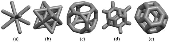
Figure 1.
Different types of lattice-frame materials with the same thickness of 2.0 mm: (a) Body-centered cubic (BCC); (b) Octet; (c) Truncated cube; (d) Truncated octahedron; (e) Kelvin cell.
Another class of lattice structure is the TPMS. The TPMS is composed of infinite, non-self-intersecting, periodic surfaces in three principal directions [16]. The first example of TPMS was the Diamond minimal surface, discovered by Schwarz [17] in 1865, and the Neovius surface, discovered by Neovius in 1833 [18]. They further discovered several minimal surfaces, e.g., Primitive and Hexagonal. Almost a century later, in 1970, Schoen introduced many types of minimal surfaces, and Gyroid was the most famous minimal surface [19]. The TPMS is characterized as a minimal surface because the curvature along the principal curvature planes is equal and opposite at every point, making the mean curvature zero (H = 0). Here, H = (k1 + k2)/2, where k1 and k2 are the maximum and minimum of the normal curvature at a given point on a surface. When the minimal surface is infinite and periodic in the three independent directions, it is called the TPMS. As an intrinsic measure of curvature, the Gaussian curvature, defined by K = k1k2, represents a local curvature within the structure at a given point. Figure 2 shows the distributions of the Gaussian curvature at each point of three different minimal surfaces as examples [20].
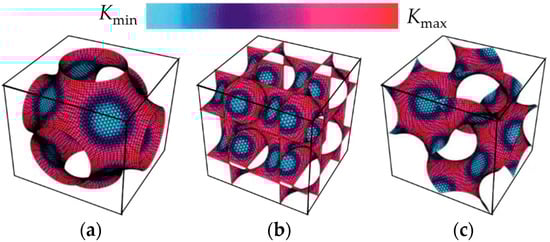
Figure 2.
Distributions of the Gaussian curvature at each point of minimal surfaces [20]: (a) Primitive; (b) Diamond; (c) Gyroid.
Mathematical algorithms are an accurate method for designing TPMS-based structures based on the minimal surface definition. Also, the TPMS can be designed by different methods, such as nodal approximation of the Weierstrass formula, numerical generations, etc. [21]. However, the level-set equation derived from a sum defined in terms of the Fourier series [20] is the simplest and most widely employed approach to create minimal surface-like structures [4,6]. The level-set equations are a group of three-dimensional trigonometric functions that satisfy the equality criterion ϕ(x,y,z) = c. The level-set equations of Schwarz-Primitive (Primitive), Schwarz-Diamond (Diamond), Schoen-Gyroid (Gyroid), and Schoen-I-graph and Wrapped Package (IWP), typically found in the literature, are described in Equations (1)–(4). The corresponding surfaces are demonstrated in Figure 3a [22]. It should be noted that several free tools for generating lattices based on TPMS are currently available [22,23].
where α, β, and γ denote constants related to the unit cell size (L) in x, y and z, respectively; c is the offset parameter, which equals zero for a single unit cell of the TPMS, as depicted in Figure 3a [22]. For the other TPMS topologies, the level-set equations and corresponding minimal surfaces, including Fischer Koch S, Neovius, Schoen F-Rhombic Didecahedra (FRD), C(I2-Y**), Fischer Koch C(Y), Fischer Koch C(±Y), and Schwarz Cross-layer of parallel (CLP) are shown in Appendix A.
Primitive: cos(2απx) + cos(2βπy) + cos(2γπz) = c
Diamond: cos(2απx)cos(2βπy)cos(2γπz) − sin(2απx)sin(2βπy)sin(2γπz) = c
Gyroid: sin(2απx)cos(2βπy) + sin(2βπy)cos(2απx) + sin(2γπz)cos(2απx) = c
IWP: 2(cos(2απx)cos(2βπy) + cos(2βπy)cos(2γπz) + cos(2γπz)cos(2απx) − (cos 2(2απx) + cos 2(2βπy) + cos 2(2γπz)) = c
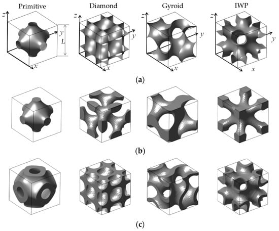
Figure 3.
Unit cell examples of typical TPMS structures at the same porosity (The TPMS structures are generated using MSLattice software [22]): (a) Minimal surfaces; (b) Solid-TPMS structures; (c) Sheet-TPMS structures.
The iso-surfaces split the space into two subdomains of equal volumes when the level-set equation is calculated at c = 0. Here, two approaches can generate the TPMS lattices based on these minimal surfaces. The first method is achieved by considering the volume bound by the minimal surface to create the solid-TPMS structure, also called the skeleton-TPMS structure, as demonstrated in Figure 3b. The second one is created by offsetting the minimal surface along its normal direction to generate a double surface. This surface is referred to as the sheet-TPMS structure, as shown in Figure 3c. With these smooth curvatures, the TPMS structures can eliminate the stress concentrations commonly found in strut-based structures.
Generally, to illustrate the merits of the lattice structures, the performances of the TPMS structures are analyzed and compared with other structures [6,7]. Among the performances in different disciplines, most of the research has focused on mechanical performances. Speirs et al. [24] showed that TPMS structures acquired superior fatigue resistance compared with the octahedron unit due to the smooth surfaces without nodal points. Khan et al. [25] demonstrated that the sheet-IWP structures showed superior viscoelastic behaviors under uniaxial loading than other lattice-frame materials. Wang et al. [26] showed that the sheet-Gyroid structure provided the best stability and exhibited the widest range of mechanical properties compared to cubic and octet-strut-based structures. Teng et al. [27] found that the sheet-Gyroid structure outperformed the BCC and truss lattice structures in stiffness, yield stress, and toughness. Overall, the TPMS-based structures provide better mechanical performance than the strut-based structures. Thus, the TPMS structures, especially the sheet-based ones, can be employed possibly in different applications requiring high mechanical strength, replacing the lattice-frame materials [28].
The TPMS structures have interconnected curvatures with non-tortuous pores, which are desirable for mass transfer or permeability applications. From the flow perspective, previous studies have focused on permeability and wall shear stress. Yet, the flow velocities considered in these investigations have been done mostly in the Darcy regime, and the non-linear inertial effects were negligible [29,30]. Ali et al. [31] observed that the sheet-Gyroid structure exhibited higher wall shear stress than the lattice-based models in the same porosity but caused comparable fluid permeability. Poltue et al. [32] further observed that the sheet-Neovius structure exhibited the highest wall shear stress but caused the lowest permeability. Montazerian et al. [33] studied cylindrical ducts of different lattice- and TPMS-based scaffolds. They found that the TPMS-based scaffolds, especially the solid-IWP structure, are more permeable than lattice-based ones in the longitudinal fluid flow direction. Also, the TPMS structures within a wide range of porosity showed higher normalized permeability values than the fiber-based structures [34]. Even though the porosity of the fiber-based structure increased the permeability, the tortuosity was significantly decreased [35], which negatively affected the fluid mixing and heat transfer performance.
Many researchers have investigated the thermal conductivity of different TPMS topologies [36,37]. According to the experimental results by Wang et al. [38], the sheet-FRD structures obtained 103% higher thermal conductivity than the commercial stochastic foams with the same porosity [39,40]. The sheet-TPMS structures also provide better thermal conductivity than the fiber-based structures since the normalized thermal conductivity values of the fiber-based porous media considerably varied with the fiber direction [41]. The main reason for the higher thermal conductivity in the sheet-TPMS structures was the excellent connectivity of the interconnected curvature.
Also, it has been observed that effective thermal conductivity strongly depends on the topologies [42]. Qureshi et al. [43] showed that the sheet-Primitive structure showed the highest value, followed by sheet-IWP and sheet-Gyroid structures, whereas the Kevin cell model showed the lowest value. Smith et al. [44] concluded that the thermal conductivity of the TPMS structures was inversely proportional to the surface area-to-volume ratio. However, the thermal performance of cooling channels was typically proportional to surface areas for convective heat transfer. Overall, the thermal conductivity for most of the sheet-TPMS structures is similar, which is considerably higher than conventionally manufactured stochastic metal foams and lattice-frame materials, as plotted in Figure 4.
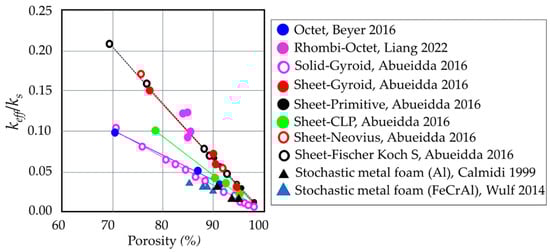
Figure 4.
Demonstrations of the normalized thermal conductivity for different unit cell structures plotted against the porosity [2]. (keff is the effective thermal conductivity, and ks is the thermal conductivity of the solid). Octet [10], Rhombi-Octet [13], Solid-Gyroid [36], Sheet-Gyroid [36], Sheet-Primitive [36], Sheet-CLP [36], Sheet-Neovius [36], Sheet-Fischer Koch S [36], Stochastic metal foam (Al) [39], Stochastic metal foam (FeCrAl) [40].
Complicated structures can improve the cooling areas of a heat exchanger with high porosity. Theoretically, the interconnected and smooth curvatures of the TPMS structures are ideal candidates for heat transfer applications. The performance properties of the TPMS structure, as mentioned above, are appropriate for further improving heat transfer efficiency. With the smooth and interconnected curvature in the TPMS heat exchanger, higher heat transfer and lower pressure loss could be expected compared to that of the porous metal fiber [45] and fin-shaped heat exchangers [46]. Also, the TPMS networks, with the large heat transfer area per unit volume, have shown better heat transfer performance in cooling channels than the lattice-frame material [47,48,49]. Although the TPMS has been implemented in actual cooling applications [50], the effects of TPMS design variables and the thermal performance advantages have been discussed by limited research.
Therefore, this review attempts to collect research studies on flow and heat transfer enhancement in cooling channels embedded with various TPMS topologies and discusses the effects of TPMS design variables on thermal performance. Comparisons between the TPMS and conventional cooling structures in different heat transfer applications are provided to show the thermal performance advantages. The fabrication methods for the TPMS-based cooling channels are also given. Moreover, recommendations for future research are outlined. Therefore, this review provides extensive literature details for the design of the next-generation and high-efficiency internal cooling channels.
2. Effects of TPMS Design Variables on Flow and Heat Transfer
For specific applications, the critical challenge encountered by TPMS designers is to select suitable TPMS topologies and optimize its design variables [51]. For heat transfer applications, the TPMS topologies and macroscopic properties, e.g., porosity (ε), wall thickness (t), and unit cell size (L), have been specified to study the flow and heat transfer characteristics of cooling channels embedded with the different TPMS models.
It should be noted that the TPMS structures for cooling channels found in the literature can be divided into two main applications: heat sinks and two fluid heat exchangers. For the first application, the solid- and sheet-TPMS structures have been employed as cooling structures for heat sink applications, as shown in Figure 5a. Cooling fluid with the prescribed temperature is inserted from the inlet, passed through the channel and the TPMS structure, and exited at the outlet. The sides of the channel and TPMS structures are generally set to the wall boundary condition or heated by a constant heat flux/a fixed temperature to compute the areas in contact with the heating plate [52,53].
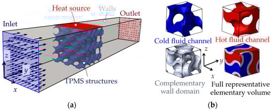
Figure 5.
Demonstration of the TPMS structures used in literature: (a) Cooling structures for heat sinks [52]; (b) Cooling structures to separate cold and hot fluid domains for heat exchangers [54].
For the second application, as the sheet-TPMS structure separates the space into two interpenetrating subdomains, the configuration is very interesting for heat exchangers when the indirect transfer of heat between two flowing streams is required. Therefore, the sheet-TPMS structure is used as a heat exchanger coupled with two fluid domains, as presented in Figure 5b. Generally, the channel includes the fluid and solid domains. For the boundary conditions in the fluid domains, the fully developed interfaces with prescribed bulk temperatures are applied to the inlet and outlet boundaries normal to the y-axial direction. The inlet temperature of the hot flow is higher than that of the cold fluid. The remaining boundaries, which are normal to the x and z directions, are associated with periodic pairs of internal interfaces to allow the fluid to pass all domains. The solid domains are set as no-slip conditions at the solid-fluid interfaces. The boundaries are set as adiabatic in the surfaces normal to the y-axial direction. For the remaining walls, normal to the x and z directions, periodic interfaces are used to allow heat conduction in the solid domain.
2.1. Parameter Definitions
In this section, the parameter definitions used to analyze the flow and heat transfer performance in different studies are first presented. In the general internal cooling system, the Reynolds number (Re) is employed to evaluate the nature of the flow. The Reynolds number is the ratio between inertial and viscous forces, defined as follows:
where ρ is the fluid density (kg/m3), V is the inlet velocity (m/s), μ is the viscosity (Pa.s), and dh is the hydraulic diameter (m) defined as 4Ac/Lp, where Ac is the cross-sectional area of the channel and Lp is the wetted perimeter of the same cross-section [53]. However, in the two fluid heat exchangers, the cross-sectional area is not constant for all TPMS topologies. Another definition for the hydraulic diameter employed in the TPMS structures is 4ε/Sv, where Sv is the specific area surface (m2/m3) [55,56].
The globally average Nusselt number () calculated from the mean convective heat transfer coefficient () is generally used to evaluate heat transfer performance in the cooling channel, defined as follows:
where Qtot is the total heat transfer (W), Aw is the interface surface area between fluid and solid or total wetted surface area (m2), kf is the fluid thermal conductivity (W/(m K)), and ΔT is the temperature difference between wall and fluid temperatures (K) [55,57,58] or the log mean temperature difference [51].
In several studies, the Sherwood number (Sh) has been adopted to analyze mass transfer found in desalination applications. The Sherwood number is the ratio between convective and diffusive mass transfers, which can be interpreted as heat transfer in the channel [59,60,61]. It can be calculated as follows:
where mavg is the average mass transfer coefficient (m/s), and D is the diffusive (m2/s).
The friction factor (f) is commonly used to compare pressure loss in cooling channels, and it can be calculated as follows:
where Δp is the pressure loss in the system (Pa), and Lc is the channel length (m).
The heat transfer performance of cooling channels is employed to compare the thermal performance after including the friction losses. The thermal performance of cooling channels (η) is defined as follows:
where and f0 are the values of the Nusselt number and friction factor, respectively, used for normalization [62], which is defined differently in the literature. Generally, for turbulent flow systems, the Dittus-Boelter equation ( = 0.023Re0.8Pr0.4 [63]) and the Blasius correlation (f0 = 0.316Re−0.25 [64]) are adopted for normalization.
In some works, the product of the average heat transfer coefficient () and wetted surface area (Aw) is plotted against the pumping power to compare the net heat dissipation capability of each TPMS topology. The pumping power (Pe) is defined based on the volume flow rates () and pressure losses (Δp) as follows:
where is the volume flow rate (m3/s).
2.2. Porosity
The porosity (ε), also known as volume fraction, is defined as the fluid volume divided by the total volume of the considered system. It has been fixed at equivalent values to compare the effects of different TPMS topologies on flow and heat transfer performance. The porosity can also be set to the same values for the uniform or graded TPMS structures. Moreover, in many investigations, the porosity of the specific TPMS topology has been varied to observe the flow and thermal transport characteristics.
2.2.1. Equivalent Porosity
Most research has analyzed the flow, heat, and mass transfer under laminar flow regimes for the uniform porosity of different TPMS structures. For heat exchanger applications, the morphology of the TPMS structures was investigated by Cheng et al. [58,65]. In their numerical model, the cold gas flowed in the TPMS structures and cooled the pore and solid matrix interface, which was heated with the constant heat flux. It was observed that the interstitial Nusselt number values for the sheet-Primitive structure increased slightly at higher Reynolds numbers. In contrast, the values for the sheet-Diamond, sheet-IWP, and sheet-Gyroid structures increased in a quasilinear manner because the complex curvatures broke the boundary layer. Among them, the sheet-IWP model exhibited the highest heat transfer, while the sheet-Primitive model caused the lowest values in the channel. However, it can be expected that the sheet-Diamond structures could provide the highest values when the Reynolds number is larger than 200.
The velocity vectors and contours inside a unit cell were demonstrated to elucidate the flow characteristics for different TPMS topologies, as shown in Figure 6. Evidently, the TPMS structures generate intensive flow mixing in their curvatures, except for the sheet-Primitive structure that causes large areas of low velocity. As seen in Figure 6a, the flow organized in the sheet-Primitive structure is in order, but the main flow has less interaction with the surface; thereby, the sheet-Primitive structure causes the lowest heat transfer. The sheet-IWP structure provides the most uniform flow distribution, followed by the sheet-Gyroid structure, as demonstrated in Figure 6b,c, respectively. In contrast, the flow characteristics of the sheet-Diamond structure are observed to be drastically disordered. The negative angle of the sheet-Diamond model generates backflow and significantly changes the flow direction, as illustrated in Figure 6d. The flow results imply that the higher specific area of the sheet-Diamond structure causes the highest pressure loss among comparative models.
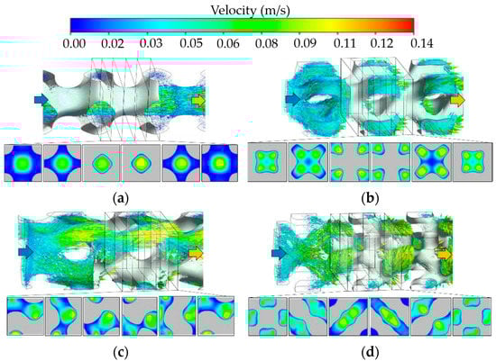
Figure 6.
Velocity fields for different TPMS structures with the same porosity at the mass flow rate of 2.5 kg/s2 (More flow details are provided by Cheng et al. [65]): (a) Sheet-Primitive; (b) Sheet-IWP; (c) Sheet-Gyroid; (d) Sheet-Diamond structures.
Kaur and Singh [47] compared the averaged heat transfer coefficient of the sheet-Gyroid and sheet-Primitive structures at an equivalent porosity for heat sink applications where the coolant flow passes the TPMS core that was heated by a constant heat flux. The numerical results showed that the sheet-Gyroid structure generated a higher heat transfer than the sheet-Primitive structure. Moreover, the sheet-Gyroid structure outperformed the sheet-Primitive structure at specific pumping power conditions, even though it caused a high pressure loss in the channel. Sreedhar et al. [66] compared different solid-based TPMS structures, i.e., Gyroid, Primitive, IWP, Fischer Koch S, and transverse Schwarz CLP (tCLP), at the Reynolds number of about 20–60. They observed that the solid-Gyroid structure significantly improved mass transfer and reduced pressure loss. Similar results were also obtained by Thomas et al. [67], which further observed that the tCLP topology showed a superior overall film heat transfer coefficient to the other TPMS structures but caused the highest pressure loss in the tested system.
The flow characteristics and heat transfer performance of a cooling channel for heat sinks at a specific porosity have also been investigated for turbulent flow regimes. Yinzheng et al. [49] numerically analyzed the heat transfer performance of the solid-Gyroid, solid-Diamond, and solid-Primitive structures. The results revealed that the solid-Diamond structure showed the highest heat transfer performance due to its larger heat dissipation area. In contrast, the solid-Primitive structure presented the lowest flow resistance in the channel. Al-Ketan et al. [53] compared the heat transfer performances between the solid-Gyroid, solid-Diamond, and sheet-Gyroid structures in a cooling channel heated on 4-side walls at the Reynolds number of about 4000–65,000 using a realizable k–ε turbulence model. The results showed that the sheet-Gyroid structure provided the highest convective heat transfer coefficient due to its complex curvature. Among these TPMS architectures, Khalil et al. [48] further reported that the solid-Diamond structure exhibited the best thermal performance as the Reynolds number increased, as shown in Figure 7, due to reasonably increased pressure loss and applicably increased heat transfer. In addition, the sheet-Gyroid structure showed the lowest in the comparison since it caused the highest-pressure loss in the channel.
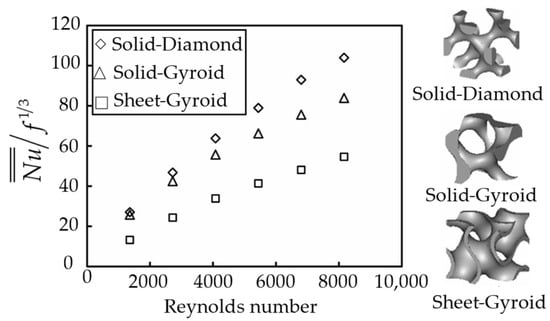
Figure 7.
Thermal performance of cooling channels for different TPMS topologies at the same porosity [48].
Al-Ketan et al. [53] explained that the pressure loss variation in the channel was because of the difference in pore size, as demonstrated in Figure 8, where the diameter of the maximum sphere (red sphere) passing through the smallest hole of the TPMS topologies was used to determine the pore size. It can be seen that the sheet-Gyroid structure, causing the highest pressure loss, has the smallest pore size, followed by the solid-Diamond and solid-Gyroid structures.
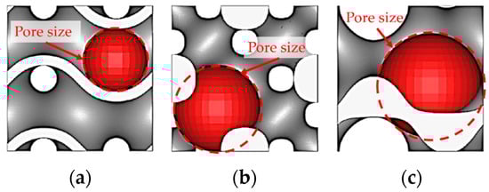
Figure 8.
The maximum sphere, passing through the smallest hole of different TPMS topologies [53]: (a) Sheet-Gyroid; (b) Solid-Diamond; (c) Solid-Gyroid structures.
Furthermore, the velocity streamlines and temperature contours from the comparative TPMS topologies have been revealed by Al-Ketan et al. [53], as shown in Figure 9. The solid-Diamond structure distributes the flow evenly in small pores, resulting in high interaction between the heating surface and the incoming flow, as seen in Figure 9a. The streamline in the middle of the solid-Diamond structure shows a uniform splitting that expands as the flow passes across the structure. The flow also continuously rotates around the smooth strut of the solid-Diamond structure. For the solid-Gyroid structure, a large flow generates low resistance to the incoming flow, causing a less dispersed manner, as shown in Figure 9b. The streamline tends to move upward due to the asymmetrical geometry in the frontal cross-section of the solid-Gyroid structure. These flow patterns lead to higher temperatures of about 30–50% than in the solid-Diamond structure, although both have a similar wetted area and the same porosity.
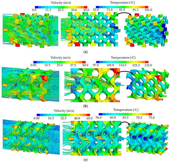
Figure 9.
Velocity streamlines and temperature contours at Re = 27,500 and heat load = 100 W [53]: (a) Solid-Diamond; (b) Solid-Gyroid; (c) Sheet-Gyroid structures.
Meanwhile, the sheet-Gyroid structure splits the incoming flow into two separate streams, as presented in Figure 9c. The streamline passing the sheet-Gyroid structure shows the largest change in trajectory and flow dispersion compared to the solid-Gyroid and solid-Diamond structures. Thus, the hot surfaces experience more interaction with the incoming coolant, enhancing the turbulence and heat transfer.
The effects of grading the porosity of the TPMS structures were also studied in several works for enhancing the thermal performance of heat sinks. Graded TPMS structure signifies the gradual increase or decrease of the TPMS porosity along the channel’s length, width, or height, which maintains the same overall porosity as the uniform TPMS ones. The example of uniform and graded sheet-Gyroid structures are demonstrated in Figure 10.
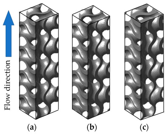
Figure 10.
Sheet-Gyroid structure with the same porosity of 70% (The TPMS structures are generated using MSLattice software [22]); (a) Uniform porosity; (b) Positive porosity; (c) Negative porosity.
Qureshi et al. [68] showed that for the sheet-Primitive, sheet-Gyroid, and sheet-IWP structures, the gradually increased porosity along the flow direction outperformed the equivalent uniform and gradually decreased porosity models in terms of conductive and convective heat transfer performances. Moreover, Al-Ketan et al. [53] showed that the graded-solid Diamond structure with porosity varying from 80.0–82.5% along the flow direction under turbulent flow regimes could reduce the pressure loss by about 27.6%, while the overall heat transfer coefficient decreased by only 15.7%. The graded TPMS structures were conceived with reasonable heat transfer reductions but could provide a better thermal performance of cooling channels. The results of the graded TPMS structures not only improve thermal performance but also result in less material consumption in additive manufacturing, rendering lightweight cooling channels. However, it is possible that the graded TPMS structures might not be better than the corresponding uniform one for particular functions due to other important considerations, e.g., mechanical strength and hydraulic performances, etc. [69].
2.2.2. Varying the Porosity
The porosity variation for a specific TPMS structure significantly affects the overall contact area, changing the flow, and mass and heat transfer in cooling channels. Sreedhar et al. [66] varied the porosity of the solid-Gyroid structure in the range of 72–90%. It was found that the solid-Gyroid model with larger porosity significantly improved mass transfer and lowered pressure loss. However, several studies found that the convective heat transfer coefficient and friction factor inversely varies with the porosity of the sheet-TPMS structures [54,70].
Qureshi et al. [68] observed that the reduction in porosity for the sheet-Primitive, sheet-Gyroid, and sheet-IWP structures significantly enhanced conductive and convective heat transfer. Similarly, Cheng et al. [58] observed that as the porosity increased for the sheet-IWP, sheet-Diamond, and sheet-Gyroid structures, the interstitial convective heat transfer coefficient in heat exchangers decreased since the velocity dropped in the channel at the larger porosity. However, the convective heat transfer coefficient for the sheet-Primitive structure increased at the higher porosity values due to the larger heat transfer area.
The velocity vector in the sheet-Primitive structure for different porosity values, as presented in Figure 11, shows that a large region of low-velocity magnitude emerges in the lower porosity model at the branches perpendicular to the flow direction. The average velocity is thus highest in the case with a porosity of 20%; however, the sheet-Primitive structure has the smallest effective heat transfer area, leading to the lowest convective heat transfer coefficient compared to the other TPMS topologies, as shown in Figure 12.
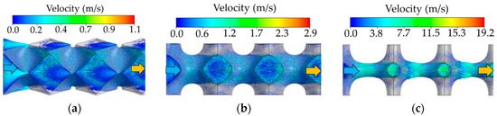
Figure 11.
Velocity vector in the sheet-Primitive structure for different porosity values: (a) ε = 70%; (b) ε = 50%; (c) ε = 20%. (More flow details are shown in Ref. [58]).
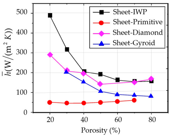
Figure 12.
Effect of porosity on convective heat transfer coefficient for different sheet-TPMS structures at Re = 40 [58].
2.3. Wall Thickness
Concerning additive manufacturing for cooling channels, the relative wall thickness (t) of different TPMS topologies has been determined to study the effects on the flow and heat transfer performance. It should be noted that due to topology differences, the values of porosity (ε), pore size (dpore), and surface area at c = 0 (ATPMS) are varied for each TPMS surface at a homogenous wall thickness and unit cell size [32], as shown in Figure 13. It can be seen that at the same wall thickness of t = 0.1 mm and unit cell size of L = 2.0 mm, the porosity, pore size, and surface area of TPMS varied significantly in different TPMS topologies. The sheet-Diamond structure has the largest surface area with the same pore size as the sheet-Gyroid structure, while the sheet-Primitive structure has the least area with the largest pore size.
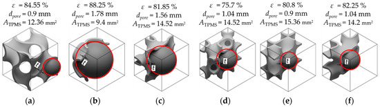
Figure 13.
Variations in porosity, pore size, and surface of TPMS at c = 0 at the wall thickness of t = 0.1 mm and unit cell size of L = 2.0 mm for a unit cell of sheet-based TPMS structures (The correlations for the porosity, pore size and surface area are provided by Poltue et al. [32]): (a) Sheet-Gyroid; (b) Sheet-Primitive; (c) Sheet-Neovius; (d) Sheet-FRD; (e) Sheet-Diamond; (f) Sheet-IWP structures.
In the laminar flow regime at the Reynolds number of less than 15, Femmer et al. [71] showed that at the same thickness of 0.4 mm, the heat exchanger with the sheet-Diamond structure exhibited a higher heat transfer performance for inherent pressure loss compared to the sheet-Gyroid, sheet-IWP, and sheet-Primitive structures. Similar results were obtained by Passos [54], in which the best thermal performance was found in the sheet-Diamond structure. Genç et al. [70] found that at the lowest thickness of 0.16 mm, the friction factors of the sheet-Diamond structure caused the highest pressure loss compared to the sheet-Gyroid and sheet-Primitive structures at the Reynolds number of less than 2500. Moreover, the friction factor decreases with increasing the Reynolds number for all TPMS geometries.
For the heat exchanger with two domains separated by infinitesimally thin walls, Iyer et al. [55] found that the sheet-Primitive structure showed the lowest Nusselt number values, whereas the sheet-Diamond structure had the best heat transfer performance, followed by the C(I2-Y**), as plotted in Figure 14a. For the friction factor, the sheet-Neovius structure caused the highest values, followed by the sheet-FRD structure, while the other TPMS structures provided a comparable pressure loss within the Reynolds numbers varying between 0–300, as illustrated in Figure 14b. They also reported that the predictions of the pressure losses are lower than Femmer et al. [71] and Kaur and Singh [47] because of smaller frictional pressure loss from the semi-infinite curvatures in their simulations.
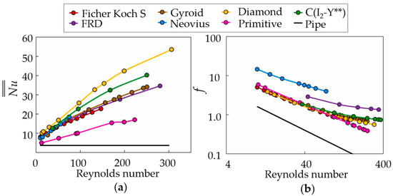
Figure 14.
Comparisons of the Nusselt number and friction factor of different TPMS topologies for the same infinitesimally thin walls (The correlations are provided by Iyer et al. [55]): (a) Averaged Nusselt numbers; (b) Friction factors.
Iyer et al. [55] further analyzed the flow patterns in different TPMS structures. It was observed that the heat transfer performance of the TPMS structures was strongly influenced by the flow field within the structure. As shown in Figure 15a,b, the continuous flow merging and splitting are evident in the sheet-Diamond and sheet-Gyroid models, which are the reason behind the high heat transfer. Meanwhile, the recirculation flow occurs in the sheet-Neovius structure, as seen in Figure 15c, leading to the highest pressure loss in the comparison. On the other hand, the fluid mixing is limited in the sheet-Primitive structure, as demonstrated in Figure 15d, resulting in less interaction of the hot and cold fluids, thereby causing the lowest heat transfer among the TPMS models.
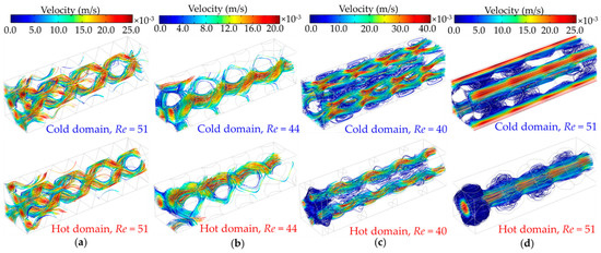
Figure 15.
Velocity streamlines in the cold and hot fluid domains at Re = 40–51. (More flow characteristics of other TPMS structures are provided in Ref. [55]): (a) Sheet-Diamond; (b) Sheet-Gyroid; (c) Sheet-Neovius; (d) Sheet-Primitive structures.
For higher Reynolds numbers, Li et al. [62] compared the flow and heat transfer characteristics of the sheet-Gyroid and sheet-Diamond structures for a homogenous wall thickness of 0.7 mm. It was observed that the thermal performance of the sheet-Gyroid structure was higher than the sheet-Diamond model within the studied Reynolds number. The different results from the previous investigations [54,55,71] can be attributed to the large turbulent kinetic energy (TKE) generation because of the flow mixing at high Reynolds numbers in the sheet-Gyroid structure, as shown in Figure 16a. This intensive fluid mixing was preferable for heat transfer enhancement.
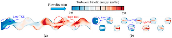
Figure 16.
Turbulent kinetic energy distribution on the center plane of the cold fluid channel at Re = 15,300 [62]: (a) Sheet-Gyroid; (b) Sheet-Diamond structures.
The different thicknesses of the sheet-Diamond structure on flow and heat transfer performance for a heat sink cooling channel under laminar flow were studied by Attarzadeh et al. [52]. They found that the larger wall thickness provided a higher convective heat transfer coefficient; however, very large wall thickness negatively affects the flow field, decreasing the thermal performance of the cooling channel. As shown in Figure 17, a continuous decay of reverse flow in the channel was observed, which reduced the pressure loss when decreasing wall thickness at the specific Reynolds number. In their study, the lowest thickness showed the best thermal performance due to low-pressure loss and a reasonable increase in heat transfer in the channel.
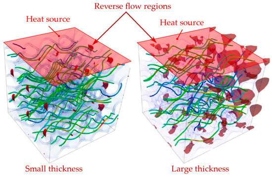
Figure 17.
Demonstrations of reverse flow regions for small thickness (left) and large thickness (right) of the sheet-Diamond structure at a specific Reynolds number [52].
Later, Attarzadeh et al. [72] established a multi-objective optimization workflow based on a Genetic Algorithm for laminar flow to reveal the optimal configurations. The sheet-Gyroid structure was used to study the TPMS design variables. It was found that increasing wall thickness improved the thermal performance of the cooling channel. They also suggested that the pore size and the wall thickness of the TPMS structure were the most Pareto-sensitive in the optimization. It should be marked that the results did not conflict with the previous findings by Attarzadeh et al. [52] because the TPMS topologies and unit cell sizes employed in the investigation are different, showing the different results between them.
2.4. Unit Cell Size
The effects of unit cell size for the TPMS topologies on the flow and heat transfer performances are rarely found in the literature. Zimmer et al. [73] measured the pressure loss in three different unit cell sizes of the sheet-Diamond structure at 8 mm, 4 mm, and 2 mm under laminar flow regimes. They found that the largest unit cell sizes caused the low-pressure loss in the tested system, while the smallest one considerably increased pressure loss, particularly at higher velocities. Similarly, Al-Ketan et al. [74] found that at the same wall thickness of 0.6 mm, the sheet-Gyroid and sheet-Primitive structures with the smaller unit cell size caused higher pressure loss due to more complex geometries and lower porosities. Attarzadeh et al. [72] studied three different cell sizes of the sheet-Gyroid structure in a cooling channel. They found that decreasing the unit cell size led to improving the thermal performance of the heat exchanger. It can be deduced that a smaller unit cell size causes higher pressure loss due to the lower porosity, but provides higher heat transfer due to the larger specific surface areas, as demonstrated in Figure 18.
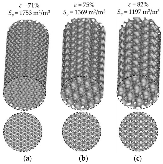
Figure 18.
The sheet-Gyroid structures with different unit cell sizes at the same thickness of 0.6 mm: (a) L = 4 mm; (b) L = 5 mm; (c) L = 6 mm [74].
3. Comparison between Conventional Cooling and TPMS-Based Structures
The TPMS structures, including the solid- and sheet-based structures, have shown specific thermal performance for different topologies and design variables, as presented in Section 2. To show the merits of the cooling channels with TPMS structures, this section reviews the investigation on heat transfer performance compared with the other cooling strategies from different cooling applications.
3.1. Two Fluid Heat Exchangers
The high surface area, smooth curvature, and surface tortuosity make the TPMS structures very preferable for forced convective cooling applications [75]. Furthermore, they contain two nonintersecting domains, allowing efficient heat exchange between two flows at different temperatures passing through the separate domains. With smooth, interconnected, and complex curvature in TPMS heat exchangers, the Deen instabilities commonly found in coiled cylindrical tubes can be eliminated.
In 2011, a method of using TPMS structures to create two-fluid heat exchangers was proposed, and the method sequences for designing heat exchangers were presented in the patent document [76]. Recently, the TPMS structures have been investigated experimentally and numerically for their heat dissipation capabilities to assess their potential for the additive manufacturing of efficient two-fluid heat exchangers. To present the thermal perforce advantages over conventional heat exchangers, Table 1 shows extensive information from the literature investigating TPMS heat exchangers.

Table 1.
Reviews of the investigation of the TPMS structures for two fluid heat exchangers.
3.2. Forced Convective Heat Sinks
Unlike conventional pin-fin or lattice-based heat sinks [15,84], the TPMS-based heat sinks have a more complex geometry, forcing the fluid to change trajectory as it flows past the heat sink [57,85]. The large surface area per unit volume, smooth curvatures, and complex topology qualify the TPMS structures to be investigated as high-performance heat sinks. Moreover, being mathematically realized, the complexity level of the TPMS-based heat sinks can be controlled to optimize thermal performance. However, very few studies explore the potential benefits of the TPMS structures in forced convection compared to traditional pin-shaped or lattice-based heat sinks.
Yinzheng [49] numerically analyzed the heat transfer dissipation for the solid-TPMS structures and the Kagome lattice structures under turbulent flow using the k–ε turbulence model. They observed that all TPMS structures outperformed the Kagome structures. At a specific velocity, the cooling effect reaches 25%, 27.2%, and 22.7% for the solid-Gyroid, Diamond, and Primitive structures, respectively, while for the Kagome structures, the cooling effect is only 15.8%.
To compare the heat transfer performance of TPMS structures, the globally averaged Nusselt number of the TPMS structures, and different cooling geometries, including dimples [86], ribs [87], latticework structures [88], pin fins [13], and micro-lattice structures [13] within the Reynolds numbers of 2000–25,000 is plotted in Figure 19. It is obvious that the TPMS structures provide higher globally averaged Nusselt numbers, especially for the solid-Diamond and solid-Gyroid structures, than the other cooling geometries. At the Reynolds number of 8000, the globally averaged Nusselt number for the solid-Diamond structure is higher than the pin fins, BCC, Octa, Kagome, and X-type lattices by about 73%, 35%, 98%, 53%, and 25%, respectively. Among the TPMS structures, the sheet-Gyroid structure causes low values of the globally averaged Nusselt numbers. On average, the solid-Diamond and solid-Gyroid structures outperform the sheet-Gyroid structure by 1.27 and 1.23 times. This increase is due to the higher surface area intersecting the flow field, as seen in Figure 9. However, it has been observed that the sheet-Gyroid structure outperformed the solid-gyroid structure at Re > 6800, attributed to the enhanced fluid mixing in the solid-Gyroid structure [48].
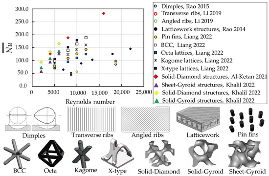
Figure 19.
Comparisons of globally averaged Nusselt number of the TPMS structures with other cooling strategies. Dimples [86], Transverse ribs [87], Angled ribs [87], Latticework structures [88], Pin fins [13], BCC [13], Octa lattices [13], Kagome lattices [13], X-type lattices [13], Solid-Diamond structures [48,53], Sheet-Gyroid structures [48], Solid-Diamond structures [48], Solid-Gyroid structures [48].
Later, Khalil et al. [48] experimentally compared the friction loss for different TPMS topologies with other periodic cooling structures, i.e., Diamond lattice [89], square lattice [89], and X-type lattice [90], as shown in Figure 20. It was mentioned that, on average, the solid-Gyroid structure exhibited lower friction factor values than the solid-Diamond and sheet-Gyroid structures by about 1.1 and 3.9. However, the solid-Gyroid and solid-Diamond structures showed lower friction factor values than those of the Diamond, square, and X-type lattices. The average friction factor values for the Diamond, square, and X-type lattices were 2.7, 1.7, and 1.3 times greater than the solid-Gyroid structure. Moreover, the solid-TPMS structures proved to have good turbulence properties and changed the coolant trajectory many times, increasing heat transfer [53]. Therefore, the thermal performance of the TPMS structures, particularly the solid-based ones, could be much better than the lattice-frame material.
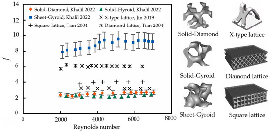
Figure 20.
Comparisons of friction factor of the TPMS structures with other periodic cooling structures [48]. Solid-Diamond [48], Solid-Gyroid [48], Sheet-Gyroid [48], Square lattice [89], Diamond lattice [89], X-type lattice [90].
The globally averaged Nusselt number ratio () with friction factor ratios (f/f0) for different geometries are plotted in Figure 21 to compare the relative performance of the cooling structures. The results show that the solid-Diamond structure provides the highest Nusselt number ratio, up to 8.0–10.0, with the friction factor ratios between 55.0–75.0. The solid-Gyroid structure shows lower Nusselt number ratios to the solid-diamond structure with similar friction factor ratios. The sheet-Gyroid structure also generates higher Nusselt number ratios than the micro-lattice structures but causes high friction factor ratios. Meanwhile, the dimples and ribs give the lowest Nusselt number ratios of about 1.5–2.0 while producing minor friction factor ratios between 1.2–3.0.
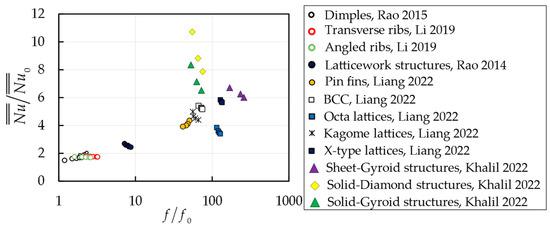
Figure 21.
Comparisons of relative thermal performance for different cooling strategies. Dimples [86], Transverse ribs [87], Angled ribs [87], Latticework structures [88], Pin fins [13], BCC [13], Octa lattices [13], Kagome lattices [13], X-type lattices [13], Solid-Diamond structures [48], Sheet-Gyroid structures [48], Solid-Diamond structures [48], Solid-Gyroid structures [48].
However, Kaur and Singh [47] showed that the real cooling performances of the TPMS structures could be recognized under a conjugate heat transfer analysis where the wetted surface area had an important role. They plotted the net heat dissipation capability of the TKD, sheet-Gyroid, and sheet-Primitive structures against the pumping power, as shown in Figure 22. It can be clearly seen that the tetrakaidecahedron (TKD) model dissipates higher heat than the sheet-Primitive structure, whereas the sheet-Gyroid outperformed the TKD structure by about 1.6–2.0 times for the range of considered pumping power.
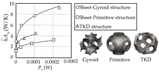
Figure 22.
Net heat dissipation capability of each topology [47].
They also showed that the heat transfer coefficient distributions provided by the sheet-Gyroid structure were higher and more uniform than the TKD and sheet-Primitive structures, respectively, as shown in Figure 23. Therefore, the TPMS structures can replace conventional and lattice-based structures to improve thermal performance and heat transfer uniformity in cooling channels.
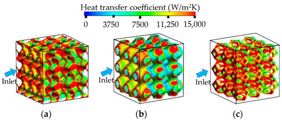
Figure 23.
Local heat transfer distribution at the velocity inlet of 7 cm/s: (a) Sheet-Gyroid; (b) sheet-Primitive; (c) TKD structures [47].
3.3. Other Applications Related to Flow, Heat, and Mass Transfer
Apart from the two-fluid heat exchanger and heat sink applications mentioned in Section 3.1 and Section 3.2, the TPMS structure is being examined as spacers in the membrane distillation to enhance heat and mass transfer [66,91]. It was found that the TPMS spacers enhanced the overall film heat transfer coefficient by 60% compared to the commercial spacers.
The larger surface area is necessary for larger chemical reactions in catalytic supports, fuel cells, and battery applications. Abu Al-Rub and Al-Ketan [92] proposed using TPMS structures as catalytic substrates. Al-Ketan et al. [74] tested the flow properties of the solid- and sheet-TPMS substrates and found that the CLP-based substrate exhibited a well-reduced pressure drop, while the sheet-Gyroid structure exhibited the highest value.
Lesmana and Aziz [93] tested the TPMS heat exchanger as the main structure of metal hydride storage to improve its performance. The comparison of different cooling conditions showed that the increase of the heat transfer coefficient improves the hydrogen sorption kinetics to a certain time. They also marked that the most significant advantage of TPMS compared to other commercial structures was its high structural strength.
Different metallic TPMS structures have been utilized as thermal conductivity enhancers for organic PMCs. It was found that the PCM embedded with the sheet-Primitive structure showed superiority in terms of heat transfer performance over the PCM-alone cases [94]. Also, Quereshi et al. [95] observed that the sheet-TPMS structures showed enhanced heat transfer performance by increasing the average heat transfer coefficient and reducing the melting time of the PCM. Fan et al. [96] found that integrating the TPMS structure in a PCM-based battery thermal management system (BTMS) showed significant improvement in reducing the battery temperature. They further combined water as a working fluid for PCM/TPMS-based BTMS, and it was observed that the average battery temperature was lower than without a cooling water system by about 40%, which eliminated the thermal saturation of PCM [97].
Recently, Qureshi et al. [98] reported the utilization of TPMS architectures impregnated with PCM for high heat flux cooling applications for the first time. It was found that the TPMS structures helped mitigate temperature under high heat flux conditions. Moreover, a change in heat sink material from aluminum powder (AlSi10Mg) to copper resulted in better temperature mitigation due to the favorable thermal conductivity.
In the free convection heat sinks, Hassan et al. [54] observed that the solid-Diamond structure showed the highest heat transfer coefficient compared to the solid- and sheet-Gyroid structures. Baobaid et al. [99] further compared these TPMS topologies for three different boundary conditions. It was found that the sheet-Gyroid structure provided superior thermal performance when opening the top and bottom surfaces of the enclosure, but its surface temperature was the highest when opening the sides and top surfaces. They concluded that the sheet-Gyroid structure with a larger surface area was opposed by the flow resistance inside the complex structure, leading to a considerable decrease in thermal performance.
4. Additive Manufacturing Methods for TPMS-Based Cooling Channels
Realizing the TPMS structures was a difficult task hindered by the limitations of conventional fabrication methods, even though these structures were discovered more than a century ago. Therefore, the TPMS structures were mostly fabricated using AM techniques, where the 3D objects were built by adding layer upon layer of material. The different manufacturing processes employed to create the TPMS-based structures were detailed in the previous literature [1,2,3,4]. However, among different AM technologies, only several techniques, i.e., powder bed fusion (PBF), stereolithography appearance (SLA), and fused deposition modeling (FDM), were used to fabricate the TPMS-based cooling channels in the recent investigation.
For the powder bed fusion (PBF), powdered material spread over the bed is melted by laser or electron beam, layer by layer. The powder not fused after a layer is used to support the next layer. The process continues until the whole TPMS structure is formed. Selective laser melting (SLM), selective laser sintering (SLS), multijet fusion (MJF), and direct metal laser sintering (DMLS) are based on this principle used to fabricate the TPMS cooling channels in a wide range of materials, e.g., aluminum alloy (AlSi10Mg), stainless steel, or thermoplastic polymer. In the PBF, the surface roughness and sticking powder have been observed to increase the pressure loss across the cooling channel with TPMS structures, while micro-voids and micro-cracks negatively affect the thermal conductivity of the heat sink. These issues, however, can be mitigated by physical, chemical, and thermal post-processing [53].
Stereolithography appearance (SLA) is a more precise additive manufacturing technology that can achieve smaller wall thicknesses and smoother surfaces than the PBF [73]. In this technique, an ultraviolet laser source (UV) is adopted to cure photosensitive liquid material on a moving tray point by point. When the tray is submerged in a transparent tank containing the material, the UV is controlled to draw the model pattern from the bottom. Once the layer is cured, the tray is lifted up, and the second layer is printed upon the first. Digital light processing (DLP) is also based on the basic principle of the SLA, but each sliced layer of the model is cured in each projection step. In many studies, most TPMS structures are fabricated by the SLA; however, this technique is limited to photosensitive materials [6].
In fused deposition modeling (FDM), the TPMS models are created by melting and extruding a filament material that solidifies after being extruded from the nozzle. The FDM has been used to fabricate air-to-air TPMS heat exchangers because it is cheaper than the other printing options [70]. This method requires support structures during fabrication, which can be removed by thermal treatment or a high-pressure jet. However, the removal processes can damage the TPMS structures; moreover, the FDM can process only polymer. Therefore, this technique is less utilized in fabricating the TPMS structure [4].
Table 2 shows the overview of AM methods for fabricating TPMS-based cooling channels in recent studies. The material used, size/thickness, and 3D-printed example are included in the table. It is observed that the PBF is the most utilized method in fabricating TPMS-based cooling channels, which can be attributed to a variety of usable materials. The size of the cooling channel ranges from about 20 mm to 150 mm, while the smallest wall thickness is observed at 0.16 mm. Even though recent investigations have only focused on the small size of the TPMS cooling channels, which is applicable for compact heat exchangers, the larger scale of the TPMS structure can be obtained due to the rapid development of AM technology.
Table 2.
Overview of AM methods for fabricating TPMS-based cooling channels in recent studies.
5. Recommendations for Future Research
According to the literature review, the effects of porosity and wall thickness of different TPMS topologies for heat exchangers are well understood. However, in most of the prior studies, the flow is laminar, which could not fully explore the potential increase in heat transfer performance for the TPMS structure. Moreover, the TPMS structures in heat sink applications are very limited and may be insufficient to apply in actual applications. Therefore, some issues can be further investigated as follows:
- Experimental investigations on heat transfer characteristics with different TPMS topologies, porosities, wall thicknesses, and unit cell sizes are required for heat sink applications, especially under turbulent flow regimes. The heat transfer characteristics on the endwall can be obtained using liquid crystal methods, which have been achieved for the lattice-frame material in previous studies [100]. Moreover, to explore the full potential of the TPMS heat transfer, the metallic TPMS structures can be additively manufactured; then, the thermocouples can be used to measure the heat transfer dissipation in steady-state experiments [101,102]. Some examples of the TPMS structures, additively manufactured by selective laser melting (SLM) using stainless steel, are shown in Figure 24;
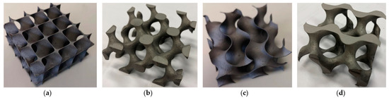 Figure 24. Examples of additively manufactured TPMS structures by SLM using stainless steel, which can be used for steady-state experiments: (a) Sheet-Diamond; (b) Solid-Diamond; (c) Sheet-Gyroid; (d) Solid-Diamond structures.
 - Apart from computational fluid dynamics (CFD) investigations, magnetic resonance imaging (MRI), which has been used by Clark et al. [30], is an appropriate technique for understanding the flow mechanisms of complex TPMS structures;
- The different cooling channel configurations can be further investigated, e.g., circular tube, narrow duct, wedge-shaped channel, etc., which could provide insight into flow and heat transfer characteristics when using TPMS structures. The uniform and graded TPMS structures can also be tested in other cooling applications, e.g., film cooling channels [103], a trailing edge of gas turbine blades [104], and recuperator heat exchangers for a gas turbine system [46], to further enhance thermal performance;
- The correlations from the TPMS cooling structures are rarely observed in previous works, particularly at high Reynolds numbers. Therefore, the correlations from a wide range of parameters have to be formulated to estimate the heat transfer and pressure loss in the cooling channel with different TPMS structures.
- Previous studies have used optimization methods to find the optimal lattice configuration structure [105]. Modrek et al. [106] also employed topology optimization with two mapping approaches to optimize natural convective heat sinks with solid- and sheet-Gyroid structures. Therefore, optimization methods are encouraged to find the optimal configurations of the forced convective cooling channel embedded with TPMS structures.
6. Conclusions
In this review, extensive studies have been reviewed to demonstrate the effects on flow and heat transfer enhancement in internal cooling channels with triply periodic minimal surfaces (TPMS) from recent experimental and numerical investigations. The extensive results consist of the effects of porosity on the flow field and heat transfer, followed by the effects of wall thickness and unit cell size. Also, the comparisons between conventional cooling and TPMS-based structures have been demonstrated. Moreover, the fabrication methods for the TPMS-based cooling channels in recent studies have been reviewed. The main conclusions can be drawn as follows:
- With the same porosity, more complex TPMS structures, e.g., Diamond and Gyroid models, provide high heat transfer as the Reynolds numbers increase but cause high-pressure loss. This is due to their tortuosity topologies and larger surface areas, significantly changing the flow characteristics. For heat sink applications, the graded TPMS structure along the flow direction could provide better thermal performance than the uniform one due to significantly decreased pressure loss with maintaining high heat transfer in the channel.
- The convective heat transfer coefficient and friction factor inversely vary with the porosity for most of the sheet-TPMS structures, except for the Primitive model, because a large high-speed area presents in the lower porosity model along the flow direction, considerably interacting with the heating walls.
- Different TPMS topologies with the same wall thickness have different porosities and surface areas, resulting in flow and heat transfer variation. Under laminar flow, the Diamond heat exchanger shows the best thermal performance, while for turbulent flow regimes, the Gyroid heat transfer exhibits better due to increased turbulent kinetic energy. The larger wall thickness provides higher convective heat transfer and pressure loss; however, due to the TPMS topologies and unit cell sizes, the wall thickness variation could affect the flow field and heat transfer enhancement differently.
- The comparisons with conventional cooling structures for the two-fluid heat exchangers show that the thermal performance is higher with the TPMS due to the smooth curvatures and large surface areas. Meanwhile, the solid-TPMS structures outperform the sheet-based ones due to much lower pressure loss for heat sink applications.
- Powder bed fusion (PBF), an additive manufacturing method, is the most used technique to fabricate TPMS-based cooling channels due to a variety of usable materials. However, recent investigations have only focused on the small size of TPMS cooling channels.
Author Contributions
Conceptualization, Y.R.; formal analysis, K.Y.; writing—original draft preparation, K.Y.; writing—review and editing, K.Y. and Y.R.; supervision, Y.R.; project administration, Y.R; methodology, K.Y.; funding acquisition, Y.R. All authors have read and agreed to the published version of the manuscript.
Funding
This research was funded by the National Science and Technology Major Project, grant number 2017-III-0009-0035 and the National Natural Science Foundation of China, grant numbers 11972230 and 51676119.
Acknowledgments
The authors would like to acknowledge and thank Hazem Mohammed for his help editing the final manuscript.
Conflicts of Interest
The authors declare no conflict of interest.
Appendix A
The level-set equations of the minimal surface found in the flow and heat transfer research, including Fischer Koch S, Neovius, FRD, C(I2-Y**), Fischer Koch C(Y), Fischer Koch C(±Y), and CLP, are described in Equations (A1–A7). The corresponding surfaces are demonstrated in Figure A1.
Fischer Koch S: cos(2απx)sin(2βπy)cos(2γπz) + cos2(2βπy)sin(2γπz)cos(2απx)+ cos2(2γπz)sin(2απx)cos(2βπy) = c
Neovius: 3(cos(2απx)cos(2βπy)cos(2γπz)) + 4cos(2απx)cos(2βπy)cos(2γπz) = c
FRD: 4cos(2απx)cos(2βπy)cos(2γπz) − cos2(2απx)cos2(2βπy) − cos2(2βπy)cos2(2γπz) − cos2(2γπz)cos2(2απx) = c
C(I2-Y**): 2sin2(2απx)cos(2βπy)sin(2γπz) + 2sin2(2βπy)cos(2γπz)sin(2απx) + 2sin2(2γπz)sin(2απx)cos(2βπy) + cos2(2απx)cos2(2βπy) + cos2(2βπy)cos2(2γπz) + cos2(2γπz)cos2(2απx) = c
Fischer Koch C(Y): −cos(2απx)cos(2βπy)cos(2γπz) − sin(2απx)sin(2βπy)sin(2γπz) + sin2(2απx)sin(2βπy) + sin(2απx)sin2(2γπz) + sin2(2απx)cos(2γπz) + cos(2απx)sin2(2βπy) + cos(2βπy)sin2(2γπz) = c
Fischer Koch C(±Y): −2cos(2απx)cos(2βπy)cos(2γπz) + sin2(2απx)sin(2βπy) + sin(2απx)sin2(2γπz) + sin2(2βπy)sin(2γπz) = c
CLP: sin(2γπz)sin(2βπy) − 0.4sin(2απx)cos(2γπz)cos(2βπy) = c

Figure A1.
Minimal surfaces for different TPMS topologies found in the flow and heat transfer research: (a) Fischer Koch S [55]; (b) Neovius [55]; (c) FRD [55]; (d) C(I2-Y**) [55]; (e) Fischer Koch C(Y) [82]; (f) Fischer Koch C(±Y) [82]; (g) CLP [74].
Figure A1.
Minimal surfaces for different TPMS topologies found in the flow and heat transfer research: (a) Fischer Koch S [55]; (b) Neovius [55]; (c) FRD [55]; (d) C(I2-Y**) [55]; (e) Fischer Koch C(Y) [82]; (f) Fischer Koch C(±Y) [82]; (g) CLP [74].

References
- Pan, C.; Han, Y.; Lu, J. Design and optimization of lattice structures: A review. Appl. Sci. 2020, 10, 6374. [Google Scholar] [CrossRef]
- Kaur, I.; Singh, P. State-of-the-art in heat exchanger additive manufacturing. Int. J. Heat Mass Transf. 2021, 178, 121600. [Google Scholar] [CrossRef]
- Kaur, I.; Singh, P. Critical evaluation of additively manufactured metal lattices for viability in advanced heat exchangers. Int. J. Heat Mass Transf. 2021, 168, 120858. [Google Scholar] [CrossRef]
- Al-Ketan, O.; Al-Rub, R.K.A. Multifunctional Mechanical Metamaterials Based on Triply Periodic Minimal Surface Lattices. Adv. Eng. Mater. 2019, 21, 1900524. [Google Scholar] [CrossRef]
- Voicu, A.D.; Hadăr, A.; Vlăsceanu, D. Benefits of 3D printing technologies for aerospace lattice structures. Sci. Bull. Nav. Acad. 2021, 24, 8–16. [Google Scholar] [CrossRef]
- Feng, J.; Fu, J.; Yao, X.; He, Y. Triply periodic minimal surface (TPMS) porous structures: From multi-scale design, precise additive manufacturing to multidisciplinary applications. Int. J. Extrem. Manuf. 2022, 4, 022001. [Google Scholar] [CrossRef]
- Al-Ketan, O.; Rowshan, R.; Al-Rub, R.K.A. Topology-mechanical property relationship of 3D printed strut, skeletal, and sheet based periodic metallic cellular materials. Addit. Manuf. 2018, 19, 167–183. [Google Scholar] [CrossRef]
- Xiao, Z.; Yang, Y.; Xiao, R.; Bai, Y.; Song, C.; Wang, D. Evaluation of topology-optimized lattice structures manufactured via selective laser melting. Mater. Des. 2018, 143, 27–37. [Google Scholar] [CrossRef]
- Kazemi, H.; Vaziri, A.; Norato, J.A. Multi-material topology optimization of lattice structures using geometry projection. Comput. Methods Appl. Mech. Eng. 2020, 363, 112895. [Google Scholar] [CrossRef]
- Beyer, C.; Figueroa, D. Design and Analysis of Lattice Structures for Additive Manufacturing. J. Manuf. Sci. Eng. Trans. ASME 2016, 138, 121014. [Google Scholar] [CrossRef]
- Dong, L.; Deshpande, V.; Wadley, H. Mechanical response of Ti-6Al-4V octet-truss lattice structures. Int. J. Solids Struct. 2015, 60, 107–124. [Google Scholar] [CrossRef]
- Ekade, P.; Krishnan, S. Fluid flow and heat transfer characteristics of octet truss lattice geometry. Int. J. Therm. Sci. 2019, 137, 253–261. [Google Scholar] [CrossRef]
- Liang, D.; He, G.; Chen, W.; Chen, Y.; Chyu, M.K. Fluid flow and heat transfer performance for micro-lattice structures fabricated by Selective Laser Melting. Int. J. Therm. Sci. 2022, 172, 107312. [Google Scholar] [CrossRef]
- Xu, L.; Ruan, Q.; Shen, Q.; Xi, L.; Gao, J.; Li, Y. Optimization design of lattice structures in internal cooling channel with variable aspect ratio of gas turbine blade. Energies 2021, 14, 3954. [Google Scholar] [CrossRef]
- Ho, J.Y.; Leong, K.C.; Wong, T.N. Experimental and numerical investigation of forced convection heat transfer in porous lattice structures produced by selective laser melting. Int. J. Therm. Sci. 2019, 137, 276–287. [Google Scholar] [CrossRef]
- Han, L.; Che, S. An Overview of Materials with Triply Periodic Minimal Surfaces and Related Geometry: From Biological Structures to Self-Assembled Systems. Adv. Mater. 2018, 30, e1705708. [Google Scholar] [CrossRef]
- Schwarz, H.A. Gesammelte Mathematische Abhandlungen; Springer: Berlin/Heidelberg, Germany, 1890. [Google Scholar]
- Neovius, E.R. Bestimmung Zweier Spezieller Periodischer Minimalflächen, Akad; Abhandlungen: Helsinki, Finland, 1883. [Google Scholar]
- Schoen, A.H. Infinite Periodic Minimal Surfaces without Self-Intersections; NASA: Washington, DC, USA, 1970. [CrossRef]
- Gandy, P.J.F.; Klinowski, J. Nodal surface approximations to the zero equipotential surfaces for cubic lattices. J. Math. Chem. 2002, 31, 1–16. [Google Scholar] [CrossRef]
- Helou, M.; Kara, S. Design, analysis and manufacturing of lattice structures: An overview. Int. J. Comput. Integr. Manuf. 2018, 31, 243–261. [Google Scholar] [CrossRef]
- Al-Ketan, O.; Al-Rub, R.K.A. MSLattice: A free software for generating uniform and graded lattices based on triply periodic minimal surfaces. Mater. Des. Process. Commun. 2020, 3, 1–10. [Google Scholar] [CrossRef]
- Jones, A.; Leary, M.; Bateman, S.; Easton, M. TPMS Designer: A tool for generating and analysing triply periodic minimal surfaces. Softw. Impacts 2021, 10, 100167. [Google Scholar] [CrossRef]
- Speirs, M.; van Hooreweder, B.; van Humbeeck, J.; Kruth, J.P. Fatigue behaviour of NiTi shape memory alloy scaffolds produced by SLM, a unit cell design comparison. J. Mech. Behav. Biomed. Mater. 2017, 70, 53–59. [Google Scholar] [CrossRef] [PubMed]
- Khan, K.A.; Al-Rub, R.K.A. Time dependent response of architectured Neovius foams. Int. J. Mech. Sci. 2017, 126, 106–119. [Google Scholar] [CrossRef]
- Wang, N.; Meenashisundaram, G.K.; Chang, S.; Fuh, J.Y.H.; Dheen, S.T.; Kumar, A.S. A comparative investigation on the mechanical properties and cytotoxicity of Cubic, Octet, and TPMS gyroid structures fabricated by selective laser melting of stainless steel 316L. J. Mech. Behav. Biomed. Mater. 2022, 129, 105151. [Google Scholar] [CrossRef] [PubMed]
- Teng, F.; Sun, Y.; Guo, S.; Gao, B.; Yu, G. Topological and Mechanical Properties of Different Lattice Structures Based on Additive Manufacturing. Micromachines 2022, 13, 1017. [Google Scholar] [CrossRef]
- Hussain, S.; Ghopa, W.A.W.; Singh, S.S.K.; Azman, A.H.; Abdullah, S. Experimental and Numerical Vibration Analysis of Octet-Truss-Lattice-Based Gas Turbine Blades. Metals 2022, 12, 340. [Google Scholar] [CrossRef]
- Ouda, M.; Al-Ketan, O.; Sreedhar, N.; Ali, M.I.H.; Al-Rub, R.K.A.; Hong, S.; Arafat, H.A. Novel static mixers based on triply periodic minimal surface (TPMS) architectures. J. Environ. Chem. Eng. 2020, 8, 104289. [Google Scholar] [CrossRef]
- Clarke, D.A.; Dolamore, F.; Fee, C.J.; Galvosas, P.; Holland, D.J. Investigation of flow through triply periodic minimal surface-structured porous media using MRI and CFD. Chem. Eng. Sci. 2021, 231, 116264. [Google Scholar] [CrossRef]
- Ali, D.; Ozalp, M.; Blanquer, S.B.G.; Onel, S. Permeability and fluid flow-induced wall shear stress in bone scaffolds with TPMS and lattice architectures: A CFD analysis. Eur. J. Mech. B Fluids 2020, 79, 376–385. [Google Scholar] [CrossRef]
- Poltue, T.; Karuna, C.; Khrueaduangkham, S.; Seehanam, S.; Promoppatum, P. Design exploration of 3D-printed triply periodic minimal surface scaffolds for bone implants. Int. J. Mech. Sci. 2021, 211, 106762. [Google Scholar] [CrossRef]
- Montazerian, H.; Zhianmanesh, M.; Davoodi, E.; Milani, A.S.; Hoorfar, M. Longitudinal and radial permeability analysis of additively manufactured porous scaffolds: Effect of pore shape and porosity. Mater. Des. 2017, 122, 146–156. [Google Scholar] [CrossRef]
- Liu, H.L.; Hwang, W.R. Permeability prediction of fibrous porous media with complex 3D architectures. Compos. Part A Appl. Sci. Manuf. 2012, 43, 2030–2038. [Google Scholar] [CrossRef]
- Huang, X.; Zhou, W.; Deng, D. Effective diffusion in fibrous porous media: A comparison study between lattice boltzmann and pore network modeling methods. Materials 2021, 14, 756. [Google Scholar] [CrossRef] [PubMed]
- Abueidda, D.W.; Al-Rub, R.K.A.; Dalaq, A.S.; Lee, D.W.; Khan, K.A.; Jasiuk, I. Effective conductivities and elastic moduli of novel foams with triply periodic minimal surfaces. Mech. Mater. 2016, 95, 102–115. [Google Scholar] [CrossRef]
- Mirabolghasemi, A.; Akbarzadeh, A.H.; Rodrigue, D.; Therriault, D. Thermal conductivity of architected cellular metamaterials. Acta Mater. 2019, 174, 61–80. [Google Scholar] [CrossRef]
- Wang, F.; Jiang, H.; Chen, Y.; Li, X. Predicting thermal and mechanical performance of stochastic and architected foams. Int. J. Heat Mass Transf. 2021, 171, 121139. [Google Scholar] [CrossRef]
- Calmidi, V.V.; Mahajan, R.L. The effective thermal conductivity of high porosity fibrous metal foams. J. Heat Transf. 1999, 121, 466–471. [Google Scholar] [CrossRef]
- Wulf, R.; Mendes, M.A.A.; Skibina, V.; Al-Zoubi, A.; Trimis, D.; Ray, S.; Gross, U. Experimental and numerical determination of effective thermal conductivity of open cell FeCrAl-alloy metal foams. Int. J. Therm. Sci. 2014, 86, 95–103. [Google Scholar] [CrossRef]
- Ni, L.; Chen, Z.; Mukhopadhyaya, P.; Zhang, X.; Wu, Q.; Yu, Q.; Miu, G. Numerical simulation on thermal performance of vacuum insulation panels with fiber /powder porous media based on CFD method. Int. J. Therm. Sci. 2022, 172, 107320. [Google Scholar] [CrossRef]
- Qureshi, Z.A.; Al-Omari, S.A.B.; Elnajjar, E.; Al-Ketan, O.; Al-Rub, R.A. Nature-inspired triply periodic minimal surface-based structures in sheet and solid configurations for performance enhancement of a low-thermal-conductivity phase-change material for latent-heat thermal-energy-storage applications. Int. J. Therm. Sci. 2022, 173, 107361. [Google Scholar] [CrossRef]
- Qureshi, Z.A.; Al-Omari, S.A.B.; Elnajjar, E.; Al-Ketan, O.; Al-Rub, R.A. Using triply periodic minimal surfaces (TPMS)-based metal foams structures as skeleton for metal-foam-PCM composites for thermal energy storage and energy management applications. Int. Commun. Heat Mass Transf. 2021, 124, 105265. [Google Scholar] [CrossRef]
- Catchpole-Smith, S.; Sélo, R.R.J.; Davis, A.W.; Ashcroft, I.A.; Tuck, C.J.; Clare, A. Thermal conductivity of TPMS lattice structures manufactured via laser powder bed fusion. Addit. Manuf. 2019, 30, 100846. [Google Scholar] [CrossRef]
- Liu, B.; Ma, B.; Wang, X.; Zhang, L.; Ye, J. Experimental Study on the Heat Transfer Performance of Porous Metal Fiber Sintered Sheet. In Proceedings of the 2016 International Conference on Advances in Energy, Environment and Chemical Science, Changsha, China, 23–24 April 2016; Atlantis Press: Paris, France, 2016; pp. 314–321. [Google Scholar] [CrossRef]
- Wang, W.; Li, B.; Tan, Y.; Li, B.; Shuai, Y. Multi-objective optimal design of NACA airfoil fin PCHE recuperator for micro-gas turbine systems. Appl. Therm. Eng. 2022, 204, 117864. [Google Scholar] [CrossRef]
- Kaur, I.; Singh, P. Flow and thermal transport characteristics of Triply-Periodic Minimal Surface (TPMS)-based gyroid and Schwarz-P cellular materials. Numer. Heat Transf. Part A Appl. 2021, 79, 553–569. [Google Scholar] [CrossRef]
- Khalil, M.; Ali, M.I.H.; Khan, K.A.; Al-Rub, R.A. Forced convection heat transfer in heat sinks with topologies based on triply periodic minimal surfaces. Case Stud. Therm. Eng. 2022, 38, 102313. [Google Scholar] [CrossRef]
- Yinzheng, Z. Numerical Analysis on Fluid-solid Coupling Cooling of Minimal Surface Lattice Structure. J. Phys. Conf. Ser. 2019, 1187, 032070. [Google Scholar] [CrossRef]
- Raja, S.; Hamulczuk, D.; Carlsson, S.D. Exploring a New Energy-Efficient Way to Heat Water: Design of a Heat Exchanger for Laundry Machine Applications Produced Using Additive Manufacturing; Chalmers University of Technology: Gothenburg, Sweden, 2020. [Google Scholar]
- Chandrasekaran, G. Arizona State University: Tempe, AZ, USA, 2018. Available online: https://core.ac.uk/download/pdf/158457046 (accessed on 13 October 2021).
- Attarzadeh, R.; Rovira, M.; Duwig, C. Design analysis of the ”Schwartz D” based heat exchanger: A numerical study. Int. J. Heat Mass Transf. 2021, 177, 121415. [Google Scholar] [CrossRef]
- Al-Ketan, O.; Ali, M.; Khalil, M.; Rowshan, R.; Khan, K.A.; Al-Rub, R.K.A. Forced Convection Computational Fluid Dynamics Analysis of Architected and Three-Dimensional Printable Heat Sinks Based on Triply Periodic Minimal Surfaces. J. Therm. Sci. Eng. Appl. 2021, 13, 021010. [Google Scholar] [CrossRef]
- Passos, A.G.P. Laminar Flow and Heat Transfer in Triply Periodic Minimal Surfaces; Lund University: Lund, Sweden, 2020; Available online: https://fenix.tecnico.ulisboa.pt/downloadFile/1126295043836646/ThesisAndrePass%0Aos.pdf (accessed on 9 October 2021).
- Iyer, J.; Moore, T.; Nguyen, D.; Roy, P.; Stolaroff, J. Heat transfer and pressure drop characteristics of heat exchangers based on triply periodic minimal and periodic nodal surfaces. Appl. Therm. Eng. 2022, 209, 118192. [Google Scholar] [CrossRef]
- Reynolds, B.W. Simulation of Flow and Heat Transfer in 3D Printable Triply Periodic Minimal Surface Heat Exchangers; University of Canterbury: Christchurch, New Zealand, 2020. [Google Scholar]
- Ali, M.I.H.; Al-Ketan, O.; Baobaid, N.; Khan, K.; Al-Rub, R.K.A. A study on the fluid flow and heat transfer for a porous architected heat sink using the idea of CFD modelling. In Proceedings of the ASME 2019 International Mechanical Engineering Congress and Exposition, Salt Lake City, UT, USA, 11–14 November 2019; Volume 8, pp. 1–6. [Google Scholar] [CrossRef]
- Cheng, Z.; Li, X.; Xu, R.; Jiang, P. Investigations on porous media customized by triply periodic minimal surface: Heat transfer correlations and strength performance. Int. Commun. Heat Mass Transf. 2021, 129, 105713. [Google Scholar] [CrossRef]
- Hagari, T.; Ishida, K.; Takeishi, K.; Komiyama, M.; Oda, Y. Experimental Study on Local Heat Transfer in a Rotating, Two-Pass Cooling Channel with Dense Array of Turbulence Promoters with Naphthalene Sublimation Method. In Proceedings of the ASME Turbo Expo, American Society of Mechanical Engineers, Düsseldorf, Germany, 16–20 June 2014; pp. 1–12. [Google Scholar] [CrossRef]
- Oh, I.; Kim, K.; Lee, D.; Park, J.; Cho, H. Local heat/mass transfer and friction loss measurement in a rotating matrix cooling channel. ASME J. Heat Transf. 2012, 134, 011901. [Google Scholar] [CrossRef]
- Park, J.; Kim, K.; Lee, D.; Cho, H.; Chyu, M. Heat transfer in rotating channel with inclined pin-fins. ASME J. Turbomach. 2011, 133, 021003. [Google Scholar] [CrossRef]
- Li, W.; Yu, G.; Yu, Z. Bioinspired heat exchangers based on triply periodic minimal surfaces for supercritical CO2 cycles. Appl. Therm. Eng. 2020, 179, 115686. [Google Scholar] [CrossRef]
- Winterton, R.H.S. Where did the Dittus and Boelter equation come from? Int. J. Heat Mass Transf. 1998, 41, 809–810. [Google Scholar] [CrossRef]
- Hager, W.H. Blasius: A life in research and education. Exp. Fluids 2003, 34, 566–571. [Google Scholar] [CrossRef]
- Cheng, Z.; Xu, R.; Jiang, P.X. Morphology, flow and heat transfer in triply periodic minimal surface based porous structures. Int. J. Heat Mass Transf. 2021, 170, 120902. [Google Scholar] [CrossRef]
- Sreedhar, N.; Thomas, N.; Al-Ketan, O.; Rowshan, R.; Hernandez, H.H.; Al-Rub, R.K.A.; Arafat, H.A. Mass transfer analysis of ultrafiltration using spacers based on triply periodic minimal surfaces: Effects of spacer design, directionality and voidage. J. Memb. Sci. 2018, 561, 89–98. [Google Scholar] [CrossRef]
- Thomas, N.; Sreedhar, N.; Al-Ketan, O.; Rowshan, R.; Al-Rub, R.K.A.; Arafat, H. 3D printed triply periodic minimal surfaces as spacers for enhanced heat and mass transfer in membrane distillation. Desalination 2018, 443, 256–271. [Google Scholar] [CrossRef]
- Qureshi, Z.A.; Al-Omari, S.A.B.; Elnajjar, E.; Al-Ketan, O.; Al-Rub, R.A. On the effect of porosity and functional grading of 3D printable triply periodic minimal surface (TPMS) based architected lattices embedded with a phase change material. Int. J. Heat Mass Transf. 2022, 183, 122111. [Google Scholar] [CrossRef]
- Karuna, C.; Poltue, T.; Khrueaduangkham, S.; Promoppatum, P. Mechanical and fluid characteristics of triply periodic minimal surface bone scaffolds under various functionally graded strategies. J. Comput. Des. Eng. 2022, 9, 1258–1278. [Google Scholar] [CrossRef]
- Genç, A.M.; Vatansever, C.; Koçak, M.; Karadeniz, Z.H. Investigation of Additively Manufactured Triply Periodic Minimal Surfaces as an Air-to-Air Heat Exchanger. In Proceedings of the REHVA 14th HVAC Word Congress, Rotterdam, The Netherlands, 22–25 May 2022. [Google Scholar] [CrossRef]
- Femmer, T.; Kuehne, A.J.C.; Wessling, M. Estimation of the structure dependent performance of 3-D rapid prototyped membranes. Chem. Eng. J. 2015, 273, 438–445. [Google Scholar] [CrossRef]
- Attarzadeh, R.; Attarzadeh-Niaki, S.H.; Duwig, C. Multi-objective optimization of TPMS-based heat exchangers for low-temperature waste heat recovery. Appl. Therm. Eng. 2022, 212, 118448. [Google Scholar] [CrossRef]
- Zimmer, A.; PachecoAraújo, J.D.; Andreassen, K.A.; Grande, C.A. Effect of Manufacturing Techniques in Pressure Drop on Triple Periodical Minimal Surface Packings. Chem. Ing. Tech. 2021, 93, 967–973. [Google Scholar] [CrossRef]
- Al-Ketan, O.; Pelanconi, M.; Ortona, A.; Al-Rub, R.K.A. Additive manufacturing of architected catalytic ceramic substrates based on triply periodic minimal surfaces. J. Am. Ceram. Soc. 2019, 102, 6176–6193. [Google Scholar] [CrossRef]
- Nguyen, D.T.; Roy, P.; Beck, V.A.; Stolaroff, J.K. Triply Periodic Minimal Surface Heat Exchangers for Supercritical CO2 Cycles. In Proceedings of the 14th International Conference on Greenhouse Gas Control Technologies, Melbourne, Australia, 21–25 October 2018; pp. 1–2. [Google Scholar]
- Slaughter, V.B. Method of using Minimal Surfaces and Minimal Skeletons to Make Heat Exchanger Components. U.S. Patent US7866377B2, 11 January 2011. Available online: https://patents.google.com/patent/US7866377B2/en (accessed on 13 September 2022).
- Peng, H.; Gao, F.; Hu, W. Design, Modeling and Characterization of Triply Periodic Minimal Surface Heat Exchangers with Additive Manufacturing. In Proceedings of the Solid Freeform Fabrication 2019: Proceedings of the 30th Annual International Solid Freeform Fabrication Symposium—An Additive Manufacturing Conference, SFF, Austin, TX, USA, 12–14 August 2019; pp. 2325–2337. [Google Scholar]
- Wadsoe, I.; Holmqvist, S. Additively Manufactured Heat Exchangers—Development and Testing, Lund University. 2020. Available online: https://lup.lub.lu.se/student-papers/search/publication/9019472 (accessed on 18 September 2022).
- Li, W.; Li, W.; Yu, Z. Heat Transfer Enhancement of Water-Cooled Triply Periodic Minimal Surface Heat Exchangers. Appl. Therm. Eng. 2022, 217, 119198. [Google Scholar] [CrossRef]
- Kim, J.; Yoo, D.J. 3D printed compact heat exchangers with mathematically defined core structures. J. Comput. Des. Eng. 2020, 7, 527–550. [Google Scholar] [CrossRef]
- Dixit, T.; Al-Hajri, E.; Paul, M.C.; Nithiarasu, P.; Kumar, S. High performance, microarchitected, compact heat exchanger enabled by 3D printing. Appl. Therm. Eng. 2022, 210, 118339. [Google Scholar] [CrossRef]
- Dharmalingam, L.K.; Aute, V.; Ling, J. Review of Triply Periodic Minimal Surface (TPMS) based Heat Exchanger Designs. In Proceedings of the International Refrigeration and Air Conditioning Conference at Purdue, West Lafayette, IN, USA, 10–14 July 2022; Available online: https://docs.lib.purdue.edu/iracc/2393/ (accessed on 18 September 2022).
- Alteneiji, M.; Ali, M.I.H.; Khan, K.A.; Al-Rub, R.K.A. Heat Transfer Effectiveness Characteristics Maps for Additively Manufactured TPMS Compact Heat Exchangers. Energy Storage Sav. 2022, 1, 153–161. [Google Scholar] [CrossRef]
- JHo, Y.; Wong, K.K.; Leong, K.C.; Wong, T.N. Convective heat transfer performance of airfoil heat sinks fabricated by selective laser melting. Int. J. Therm. Sci. 2017, 114, 213–228. [Google Scholar] [CrossRef]
- Ali, M.I.H.; Al-Ketan, O.; Alhammadi, A.; Khalil, M.; Khan, K.; Al-Rub, R.K.A. Heat transfer characterization of 3D printable architected heat sinks. In Proceedings of the ASME International Mechanical Engineering Congress and Exposition, Salt Lake City, UT, USA, 11–14 November 2019; pp. 1–6. [Google Scholar] [CrossRef]
- Rao, Y.; Feng, Y.; Li, B.; Weigand, B. Experimental and numerical study of heat transfer and flow friction in channels with dimples of different shapes. J. Heat Transf. 2015, 137, 031901. [Google Scholar] [CrossRef]
- Li, Y.; Rao, Y.; Wang, D.; Zhang, P.; Wu, X. Heat transfer and pressure loss of turbulent flow in channels with miniature structured ribs on one wall. Int. J. Heat Mass Transf. 2019, 131, 584–593. [Google Scholar] [CrossRef]
- Rao, Y.; Zang, S. Flow and heat transfer characteristics in latticework cooling channels with dimple vortex generators. ASME J. Turbomach. 2014, 136, 021017. [Google Scholar] [CrossRef]
- Tian, J.; Kim, T.; Lu, T.J.; Hodson, H.P.; Queheillalt, D.T.; Sypeck, D.J.; Wadley, H.N.G. The effects of topology upon fluid-flow and heat-transfer within cellular copper structures. Int. J. Heat Mass Transf. 2004, 47, 3171–3186. [Google Scholar] [CrossRef]
- Jin, X.; Li, Y.; Yan, H.; Xie, G. Comparative study of flow structures and heat transfer enhancement in a metallic lattice fabricated by metal sheet folding: Effects of punching location shift. Int. J. Heat Mass Transf. 2019, 134, 209–225. [Google Scholar] [CrossRef]
- Thomas, N.; Sreedhar, N.; Al-Ketan, O.; Rowshan, R.; Al-Rub, R.K.A.; Arafat, H. 3D printed spacers based on TPMS architectures for scaling control in membrane distillation. J. Memb. Sci. 2019, 581, 38–49. [Google Scholar] [CrossRef]
- Al-Rub, R.K.A.; Al-Ketan, O. Catalytic Converter Substrates Comprising Triply Periodic Minimal Surfaces. U.S. Patent US2019/0145298A1, 29 March 2019. Available online: https://patentimages.storage.googleapis.com/b6/eb/3b/4e24fd37612678/US20190145298A1.pdf (accessed on 20 September 2022).
- Lesmana, L.A.; Aziz, M. Triply Periodic Minimal Surface-Based Heat Exchanger as Metal Hydride Hydrogen Storage Reactor. Chem. Eng. Trans. 2021, 88, 229–234. [Google Scholar] [CrossRef]
- Qureshi, Z.A.; al Omari, S.A.B.; Elnajjar, E.; Mahmoud, F.; Al-Ketan, O.; Al-Rub, R.A. Thermal characterization of 3D-Printed lattices based on triply periodic minimal surfaces embedded with organic phase change material. Case Stud. Therm. Eng. 2021, 27, 101315. [Google Scholar] [CrossRef]
- Qureshi, Z.A.; Elnajjar, E.; Al-Ketan, O.; Al-Rub, R.A.; Al-Omari, S.B. Heat transfer performance of a finned metal foam-phase change material (FMF-PCM) system incorporating triply periodic minimal surfaces (TPMS). Int. J. Heat Mass Transf. 2021, 170, 121001. [Google Scholar] [CrossRef]
- Fan, Z.; Gao, R.; Liu, S. Thermal conductivity enhancement and thermal saturation elimination designs of battery thermal management system for phase change materials based on triply periodic minimal surface. Energy 2022, 259, 125091. [Google Scholar] [CrossRef]
- Fan, Z.; Gao, R.; Liu, S. A novel battery thermal management system based on P type triply periodic minimal surface. Int. J. Heat Mass Transf. 2022, 194, 123090. [Google Scholar] [CrossRef]
- Qureshi, Z.A.; Al-Omari, S.A.B.; Elnajjar, E.; Al-Ketan, O.; Al-Rub, R.A. Architected Lattices Embedded with Phase Change Materials for Thermal Management of High-Power Electronics: A Numerical Study. Appl. Therm. Eng. 2022, 219, 119420. [Google Scholar] [CrossRef]
- Baobaid, N.; Ali, M.I.; Khan, K.A.; Al-Rub, R.K.A. Fluid flow and heat transfer of porous TPMS architected heat sinks in free convection environment. Case Stud. Therm. Eng. 2022, 33, 101944. [Google Scholar] [CrossRef]
- Kaur, I.; Singh, P. Endwall heat transfer characteristics of octahedron family lattice-frame materials. Int. Commun. Heat Mass Transf. 2021, 127, 105522. [Google Scholar] [CrossRef]
- Rao, Y.; Wan, C.; Xu, Y. An experimental study of pressure loss and heat transfer in the pin fin-dimple channels with various dimple depths. Int. J. Heat Mass Transf. 2012, 55, 6723–6733. [Google Scholar] [CrossRef]
- Son, K.N.; Weibel, J.A.; Kumaresan, V.; Garimella, S.V. Design of multifunctional lattice-frame materials for compact heat exchangers. Int. J. Heat Mass Transf. 2017, 115, 619–629. [Google Scholar] [CrossRef]
- Zheng, D.; Wang, X.; Yuan, Q. Numerical Investigation on the Effects of Vortex Generator Locations on Film Cooling Performance. Int. J. Turbo Jet Engines 2022, 39, 25–36. [Google Scholar] [CrossRef]
- Kaur, I.; Aider, Y.; Nithyanandam, K.; Singh, P. Thermal-hydraulic performance of additively manufactured lattices for gas turbine blade trailing edge cooling. Appl. Therm. Eng. 2022, 211, 118461. [Google Scholar] [CrossRef]
- Takezawa, A.; Zhang, X.; Kitamura, M. Optimization of an additively manufactured functionally graded lattice structure with liquid cooling considering structural performances. Int. J. Heat Mass Transf. 2019, 143, 118564. [Google Scholar] [CrossRef]
- Modrek, M.; Viswanath, A.; Khan, K.A.; Ali, M.I.H.; Al-Rub, R.K.A. An optimization case study to design additively manufacturable porous heat sinks based on triply periodic minimal surface (TPMS) lattices. Case Stud. Therm. Eng. 2022, 36, 102161. [Google Scholar] [CrossRef]


Publisher’s Note: MDPI stays neutral with regard to jurisdictional claims in published maps and institutional affiliations. |
© 2022 by the authors. Licensee MDPI, Basel, Switzerland. This article is an open access article distributed under the terms and conditions of the Creative Commons Attribution (CC BY) license (https://creativecommons.org/licenses/by/4.0/).