
Influence of the Design of a Residual Current Device on Its Break Time


Faculty of Electrical Engineering, Czestochowa University of Technology, 42-201 Czestochowa, Poland
Energies 2022, 15(23), 9054; https://doi.org/10.3390/en15239054
Submission received: 9 November 2022
/
Revised: 19 November 2022
/
Accepted: 23 November 2022
/
Published: 29 November 2022
Abstract
:Residual current devices (RCDs) are devices that can provide very good protection measures against electric shock. Yet, under certain circumstances, they can cause unnecessary and unexpected switching off of power in the protected circuits. The main component that determines the properties of an RCD is the summation current transformer. In recently produced RCDs, whose operation is independent from the installation voltage, the summation transformer, apart from detection of the residual current, has yet another task: it must also provide an appropriate energy value to the electromagnetic release in order to carry out mechanical disconnection of the contacts. In this type of RCD, the core of the summation transformer should be made of magnetic material with very high permeability and appropriate geometric dimensions. Manufacturers of RCDs, in order to reduce production costs and to promote miniaturization of the devices, use cores for summation transformers made of amorphous or nanocrystalline materials quite often. In such RCD designs, the impedance-matching circuit is used in the secondary circuit of the summation transformer to ensure proper sensitivity to the residual current. The paper describes the impact of using additional impedance-matching elements in the secondary circuit on the RCD break time. The paper presents the results of tests and measurements of the RCD break times of various internal structures.
1. Introduction
Safety standards resulting from applicable regulations and standards rule the processes of design and development for electrical installations, thus minimizing the risk of electric shock during their operation. The basic principle of protection against electric shock demands that active (“live”) parts should not be accessible, and other conductive parts should not be dangerous in normal operation conditions or in the event of a single fault [1]. In low-voltage electrical installations, protection against electric shock should consist of an appropriately selected primary protection measure and an independent protection measure in the event of a fault or an enhanced protection measure that provides both basic protection and protection in case of damage. In special conditions, resulting from the intended use of the room or due to the influence of external conditions, the standard [2] requires the use of additional protection measures.
The most frequently used means of additional electric shock protection in low-voltage alternating current (AC) electrical installations are residual current devices (RCDs). The standard [2] requires the use of residual current devices with a rated current of not more than 30 mA in socket circuits with the rated current not exceeding 32 A, which can be operated by ordinary persons and are intended for general use, and in circuits supplying portable devices with a current up to and including 32 A, which are used outdoors. Additionally, RCDs with currents of IΔn ≤ 30 mA should be used in all final lighting circuits of alternating current installations in individual households [2].
Highly sensitive RCDs with currents IΔn ≤ 30 mA are devices that provide very good protection against electric shock as well as fire protection, causing an automatic disconnection of power in the protected circuit of the electrical installation in fault conditions. For RCDs intended to provide additional protection in low-voltage circuits, the correct tripping range should be from 15 mA to 30 mA. The break and non-break time limits for RCDs are specified in the standards [3,4].
The maximum break times for general purpose RCDs, defined in Table 1, are in line with the recommendations of IEC TS 60479-1:2016 [5] (page 43), which is considered the limiting value for the let go threshold current, above which a person being shocked cannot release him or herself.
Table 1 shows the maximum allowable break times for general purpose RCDs, as defined in the standards [3,4]. For these RCDs, there are no defined minimum break times (Table 1). RCDs with a short operating times are a very good means of protection against electric shock in case of damage in a protected circuit, but they can also cause unnecessary shutdowns, described, for example, in [6,7,8]. Accidental tripping occurs for no apparent reason, and after reconnecting the RCD, the entire system works properly. Among the possible causes of accidental tripping, distortions and higher harmonics in the residual current are mentioned quite often [9,10,11,12,13,14,15,16]. A frequently described problem is to ensure an appropriate level of protection against electric shock in circuits with variable speed drive systems [17,18]. In this type of circuit, there are differential currents of variable frequencies, whose spectrum depends on the pulse width modulation (PWM) frequency and on the instant rotational speed of the motor [19,20]. Research has also been carried out on the influence of the low-current frequency [21], DC currents [22,23], the use of arc fault detection devices in circuits [24,25] and the type of installation layout [26,27] on the effectiveness of RCD circuit breakers.
This paper describes the research carried out related to the influence of the internal RCD structure on its break times for various waveforms of test currents. It is a very important issue related to the necessity that the RCDs ensure an appropriate level of electric shock safety in the circuits of an electrical installation. The obtained results of laboratory tests for various types of RCDs are presented.
2. Internal Design of an RCD Circuit Breaker
The operation principle of most of RCDs available on the market does not depend on the installation voltage (Figure 1).
In this type of circuit breaker (Figure 1), the secondary circuit of the summation current transformer (1) directly feeds the electromagnetic release with the dropped armature (2), which mechanically disconnects the main contacts (3). Additional electronic components can be installed in the secondary circuit of the summation current transformer, which detects the leakage current of the protected circuit. These components provide sufficient time delay for RCD tripping or eliminate unnecessary tripping in the case of transient current pulses [28].
The main element that determines the properties of an RCD is the summation current transformer. This transformer, apart from detection of the residual current, must also provide an appropriate amount of energy to the electromagnetic release to disconnect the contacts. In the described case, when the power consumed by the release comes directly from the summation transformer, an important role is played by the impedance matching of the load (trigger) to the source (transformer) [29].
The value of the signal in the secondary circuit of the summation transformer is determined by the range of changes in the magnetic induction in its core caused by the primary differential current. In the case of RCDs with currents IΔn ≤ 30 mA, the power obtained in the secondary circuit of the transformer is very small.
3. Equivalent Diagram of the Summation Current Transformer
The current transformer, in which magnetic coupling of the windings plays a paramount role, is usually described with an equivalent diagram with all quantities accounted for at one side of the windings. In the case of an RCD device (Figure 1), the contributions from the currents in all three phases and the neutral wire current are summed up. The voltage induced in the secondary winding may be written as
where ML1, ML2, ML3 and MN are the mutual inductances between the primary wires L1, L2, L3, and N and the secondary winding, respectively.
Assume that the mutual inductances are not equal such that
Then, the relationship (1) may be written as
In cases where the protected installation circuit works properly, and there are no significant leakage currents, the sum of the primary currents is equal to zero:
In the cases of breakdown or indirect contact within the protected circuit of the installation behind the RCD, the earth current iΔ, would flow, and thus
The relationship in Equation (3), in this case, may be written as
Because of non-uniform coupling between the primary windings and the secondary winding in Equations (3) and (6), an additional error term will appear in the considered case that is proportional to the current in phase L1:
The equivalent diagram recalculated to the secondary winding w2, taking into account Equation (6), takes the form depicted in Figure 2.
The equivalent diagram depicted in Figure 2 will serve as the starting point for the analysis of RCD operation and application of impedance matching in order to obtain the maximum power on the electromagnetic release (ZW).
4. Analysis of RCD Internal Design
To ensure correct tripping, the summation transformer in the RCD, together with the secondary circuit, must meet two basic conditions:
- -
- -
- The fault voltage which appears when the maximum long-term load current of the circuit breaker flows should not cause unnecessary shutdowns.
For RCDs intended to provide additional protection in low-voltage circuits [2], the correct tripping range is 15–30 mA for a primary differential current. When selecting the summation transformer and the construction of the secondary circuit for this type of RCD, two dependencies are taken into account:
- -
- The summation transformer should have a possibly high value of impedance in the magnetizing branch, determined by the inductance Lμ and resistance RFe, (cf. Figure 2);
- -
- Impedance matching of the secondary load of the summation transformer to the impedance of the magnetizing branch in the transformer is taken into account in order to ensure maximum power dissipation at the load.
In the currently produced RCDs, in order to guarantee the correct tripping threshold, the impedance matching of the load to the impedance of the transverse branch is used more and more often, which results in separation of the maximum power on the electromagnetic release (ZW).
By simplifying the diagram from Figure 2, when skipping L′1, R′1 and eu, one obtains the diagram depicted in Figure 3. Assume that load impedance for the summation transformer is equal to
Then, the power dissipated at the load impedance Zobc is given with the relationship
or after some transformations
where β is the difference of arguments of the impedances Zμ and Zobc.
The impedance value Zobc, for which the maximum power is dissipated at a prescribed current value I′Δ, is computed from setting the derivative of power S with respect to an impedance Zobc of zero such that
It is straightforward to derive that this condition is fulfilled when
If the relationship in Equation (12) holds, then the maximal power is given with the expression
From the relationship given above, it follows that one should aim at setting a large difference between the impedance arguments, showing that one should strive to obtain a large difference in the impedance Zμ and Zobc arguments (90° is the best value). In practice, this difference is greatest when the secondary current i2 is in phase with the voltage induced in the secondary circuit of the summation transformer. This is achieved by including a series capacitor in the secondary circuit selected to compensate for the inductive reactance of the secondary circuit (Figure 4).
If the reactance XC (Figure 4) is chosen so that the condition
is fulfilled, then the maximum power dissipated at load will be given with the expression
The condition of impedance matching of the load (electromagnetic release to the source (summation transformer)) is fulfilled, assuming that the frequency of the differential current is the main frequency (50 Hz in Poland) and the following relationship is valid:
The presence of power electronic devices in the circuits of the electrical installation results in the generation of differential currents whose waveforms are significantly distorted from pure sine waves. In some cases, components with higher harmonics dominate the residual current waveform. For frequencies other than 50 Hz, RCDs with the impedance-matching circuit (selected for the frequency of 50 Hz) may not provide the appropriate level of electric shock protection required by the standards [28].
5. Measurement Systems for Determination of Break Times in RCD Devices
The measurements of the break time were carried out at a laboratory stand using two options for the measurement set-up.
5.1. Measurement Setup: The First Option
In the first considered set-up (Figure 5), the response time was measured with a specialist MRP-201 meter manufactured by Sonel [30]. The aforementioned meter is a device for measuring all types of RCDs (instantaneous, short time delay, and selective) of the types AC, A, and B in accordance with the requirements of the standards [3,4,31]. The MRP-201 meter enables measurement of the tripping current and RCD break time, depending on the value of the differential current. Measurements can be performed individually or in series. In automatic mode, measurements are made for the selected excitation waveform or a series of measurements for all available excitation waveforms. The following test current shapes are available in the measurement procedure: sinusoidal (initial positive (0°) or negative (180°) phase), pulsating one half (positive or negative), pulsating one half with a constant component (positive or negative), and constant (positive or negative). The meter also enabled a simultaneous measurement of the tripping current and break time with one tripping of the tested RCD. The measurement range of the tripping current, depending on the selected measurement procedure, was from 1.5 mA to 600 mA (accuracy ± 10% IΔn) with an operation time from 0 ms to 500 ms (accuracy ± (2% m.v. + 2 digits)).
During measurements, the considered RCD device was supplied directly from a 230 V AC installation (L, N, PE). The tests were carried out for AC- and A-type RCDs, and therefore the measurement procedure took into account only the inputs with the differential current of the following waveforms: sinusoidal (initial phase 0°), sinusoidal (initial phase 180°), one-half positive, and one-half negative with set values (30 mA, 60 mA, and 150 mA). During the tests, the differential current waveforms with a biased DC component were skipped, since such signals cannot be recognized by RCDs of the AC and A types. On the oscilloscope, with the use of a voltage and current probe, the supply voltage and differential current waveforms were recorded for individual measurements.
5.2. Measurement Setup: The Second Option
In the second considered case (Figure 6), a sinusoidal voltage wave with a given initial phase was forced by a generator (GEN). With the amplifier and the resistor (R), the rms value of the current flowing through the tested RCD was controlled. The voltage waveform from the generator amplified in the amplifier as well as the differential current waveforms were recorded on the oscilloscope and the operating times of the tested RCD were measured.
The measurements of the break time were carried out for sinusoidal differential currents with the rms values 30, 60, and 150 mA (50 Hz). The use of the measuring system in the second case (Figure 6) made it possible to carry out measurements of the break time for different initial phases of the differential current. The initial phase of the forcing run was set on the generator (GEN) in steps of 15° for the entire range from od 0° to 360°.
6. Technical Parameters of the Tested RCDs
Laboratory tests were carried out for RCDs from various manufacturers which are generally available and commonly used in low-voltage electrical installations. The following section describes the measurement results obtained for the eight selected RCDs with the technical parameters listed in Table 2.
The devices, marked as RCD-1 and RCD-2, were RCBOs with built-in overcurrent elements B16 and C16, respectively. The remaining RCD-3–8 circuit breakers were RCCBs with the permissible long-term load current In = 25 A or 40 A (type AC or A, with 2P or 4P poles, respectively). For all tested RCDs, the rated residual current IΔn was 30 mA. Figure 7, Figure 8, Figure 9 and Figure 10 show diagrams of the internal constructions of the tested RCDs listed in Table 2.
In the circuit breakers from RCD-1 to RCD-5, the impedance matching systems were used in the secondary circuit of the summation transformer. The circuit breakers differed in the number of winding turns, in the configuration of elements in the secondary circuit, and in the values of individual elements (capacitors and resistors). In all circuit breakers (RCD-1–5), diodes connected in a push-pull set-up are used to eliminate unnecessary disconnections at momentary current pulses [29,32]. In the circuit breakers from RCD-6 to RCD-8, the electromagnetic release (ZW) was supplied directly from the secondary winding. A characteristic feature is the small number of turns in the secondary winding. In circuit breakers RCD-6 and RCD-8, an additional secondary winding is used, supplying the elements to eliminate unnecessary shutdowns with temporary current pulses.
7. The Results of Laboratory Tests
7.1. The Results from the First Measurement System
Table 3 summarizes the measured break times of the tested RCDs with the use of the MRP-201 meter (measuring system shown in Figure 5). Measurements were made for differential currents of 30, 60, and 150 mA and in AUTO mode (simultaneous measurement of the activation time and current).
All measured RCD break times met the requirements specified in the standards [3,4]. The test current was in phase with the supply voltage with a frequency of 50 Hz, where the initial phase was 0°. Figure 11 shows an example of the voltage and tripping current of RCD-2 for IΔn = 30 mA, with the measured break time being 35 ms (Table 3).
The MRP-201 meter enabled the measurement of the RCD break time with excitation by currents of various shapes. Table 4 presents the obtained response times of the tested circuit breakers for the selected waveforms of the test current.
Tests were carried out for four shapes of differential currents: sinusoidal (initial phase of 0°, initial phase of 180°) and sinusoidal one half (positive and negative). The tested AC RCDs (RCD-2, 3, 5, 7, and 8) were dedicated to the detection of sinusoidal residual currents. In the case of circuit breakers marked RCD-7 and RCD-8, no tripping for a negative one-half sinusoidal input is permissible. In addition, the type-A RCDs should detect sinusoidal residual currents in one half period. The tested A-type circuit breakers (RCD-1, 4, and 6) met the criteria in this respect, resulting from the requirements of the standards [3,4].
Figure 12 shows an example of the voltage and tripping current of the RCD-2 circuit breaker (Table 4) for a one-half sinusoidal input with negative polarity.
The presented waveform in Figure 12 corresponds to the excitation with the 30 mA current (50 Hz), where the measured time of the circuit breaker operation was 28 ms.
7.2. The Results from the Second Measurement System
The application of the second measurement system (Figure 6) made it possible to measure the RCD break time for excitation with a sinusoidal current and various initial phases. The initial phase of the forcing run was set on the generator in steps of 15° for the entire range of 360°. Figure 13 and Figure 14 show the sample waveforms recorded on the oscilloscope obtained during the tests for the phases of excitation of 0° and 90°.
The measurements carried out for individual RCDs showed differences in the break time, depending on the initial phase of the forcing current. Figure 15 shows the differences in the break time values obtained from the measurements of the circuit breakers’ break time values with the applied impedance matching system in the secondary circuit of the summation transformer (RCD-1–5).
The operating times for circuit breakers RCD-1–5 (Figure 15) were in the range from 14 ms to 44 ms. The switch marked with the RCD-1 symbol was characterized by the shortest switching off times, and the maximum switching off time occurred for the initial phase of the forcing current of 150°. The remaining RCD-2–5 circuit breakers showed a similar dependence of the break time on the initial phase of the current, and the maximum break times occurred for the initial phase in the range of 30–60°. For the entire range, the switch marked with the RCD-2 symbol (28–44 ms) had the longest switch-off times.
Figure 16 shows how the break time values varied for the RCDs without the impedance-matching system in the secondary circuit of the summation transformer (RCD-6–8).
The device marked as RCD-6 showed very short operating times in the range from 13 to 24 ms (Figure 16). The RCD-7 circuit breaker, in the range from 0° to 180°, showed short operating times (11–21 ms), while in the range from 180° to 360°, the operating times varied, depending on the initial phase (maximum operating time of 168 ms, which occurred for the phase at 255°). The RCD-8 circuit breaker showed the highest variations in the break time. The shortest times (19–22 ms) occurred for the initial phase of the current forcing at 0° and 180°, while the longest activation times were 146–150 ms for the initial phases in the ranges of 75–105° and 255–305°.
Figure 17 shows the dependence of the break time of the circuit breaker designated as RCD-8 (schematic diagram in Figure 10b) versus the starting phase angle of the test current for its three values: 30 mA, 60 mA, and 150 mA. This device was characterized by a large dependence of the break time on the set initial phase of the current input. The longest break times occurred for the values of the initial phase of the current excitation close to 90° and 270°.
The RCD-8 circuit breaker did not meet the requirements specified in the standards [3,4] for the 150 mA current excitation (Figure 17), and the operation time for the initial phase values of the current excitation close to 90° and 270° was longer than 40 ms (the measured values were 48 ms at maximum). For the 0° and 180° current forcing phases, the activation times were very similar to each other (20–23 ms), regardless of the value of the test current.
8. Conclusions
The conducted tests showed that the RCD break time depended on the waveform and the initial phase of the test current.
Considering the additional protection provided as an automatic power cut-off as well as additional protection, all tested RCDs proved its effectiveness by switching off the damaged part of the electrical installation at times shorter than the requirements specified in the standards [3,4] (except for RCD-8 for IΔ = 150 mA).
Measurements of the break time carried out for a sinusoidal input (30 mA, initial phase of 0°) with the MRP-201 meter (Table 3) showed that the circuit breakers with an impedance-matching system in the secondary circuit of the summation transformer broke the circuit within 25–35 ms, whereas devices RCD-6–8, in which the electromagnetic release was directly supplied from the summation transformer, reacted within the range of 8–18 ms. An increase in the tripping current value (60 and 150 mA) directly reduced the RCD break time.
In the cases of excitation with a sinusoidal, one-half positive, and negative current (Table 4), the operating times for the individual circuit breakers were shorter.
The RCD-7 circuit breaker, in the range from 0° to 180°, showed short operating times (11–21 ms), while in the range from 180° to 360°, the operating times varied depending on the initial phase (maximum operating time of 168 ms occurred for the phase of 255°). The RCD-8 circuit breaker showed the highest variation in the break time. The shortest times (19–22 ms) occurred for the initial phase of the current forcing at 0° and 180°, while the longest activation times were 146–150 ms for the initial phases in the ranges 75–105° and 255–305°.
The device marked as RCD-6 showed very short operating times in the range from 13 to 24 ms (Figure 16). When comparing the internal structures of the RCD-6 and RCD-8 circuit breakers, the difference between them relied on the use of a 150 nF capacitor in the former, connected in parallel with the diodes (Figure 9b and Figure 10b).
When analyzing the obtained results, it can be concluded that the RCDs with the applied impedance-matching system were characterized by a small variation of the switch-off time, depending on the initial phase of the forcing current.
All tested circuit breakers, and in particular the RCD-6 circuit breaker, may cause unnecessary shutdowns of the installation circuits in the case of temporary current pulses arising in the protected circuits. Such cases occur in circuits with built-in or connected electronic devices, such as computers, UPS power supplies, and LED luminaires. In the case of lighting circuits, unnecessary tripping of RCDs may cause dangerous situations for users (loss of basic lighting).
Specialized meters for periodic tests of electrical installations available on the market, such as MRP-201, MPI-502, and MPI-530, enable measurements of RCD break times only for tripping currents IΔ with angles of 0° or 180°. Meters of this type lack the possibility to carry out measurements for the triggering angles of 90° or 180°, when the longest break times are obtained for RCDs without the impedance-matching system.
The results of the study may be useful, particularly for the RCD designers, but the author believes that this paper may shed some light on the necessity to carry out appropriate designs of electrical installations and their protection systems in order to avoid electric shocks.
Funding
This research received no external funding.
Institutional Review Board Statement
Not applicable.
Informed Consent Statement
Not applicable.
Data Availability Statement
Data are contained within the article.
Conflicts of Interest
The author declares no conflict of interest.
References
- IEC 61140:2016; Protection against Electric Shock-Common Aspects for Installation and Equipment. International Electrotechnical Commission: Geneva, Switzerland, 2016.
- HD 60364-4-41:2017; Low-Voltage Electrical Installations-Part 4-41: Protection for Safety-Protection against Electric Shock. European Committee for Electrotechnical Standardization: Brussels, Belgium, 2017.
- IEC 61008-1:2010; Residual Current Operated Circuit-Breakers Without Integral Overcurrent Protection for Household and Similar Uses (RCCB)—Part 1: General Rules. International Electrotechnical Commission: Geneva, Switzerland, 2010.
- IEC 61009-1:2013; Residual Current Operated Circuit Breakers with Integral Overcurrent Protection for Household and Similar Uses (RCBOs)—Part 1: General Rules. International Electrotechnical Commission: Geneva, Switzerland, 2013.
- IEC TS 60479-1:2016; Effects of Current on Human Beings and Livestock. Part 1: General Aspects. International Electrotechnical Commission: Geneva, Switzerland, 2016.
- Roldan-Porta, C.; Escriva-Escriva, G.; Carcel-Carrasco, F.J.; Roldan-Blay, C. Nuisance tripping of residual current circuit breakers: A practical case. Electr. Power Syst. Res. 2014, 106, 180–187. [Google Scholar] [CrossRef]
- Gurevich, V. RCD Nuisance Tripping: Who’s Guilty and What Needs to be Done? Glob. J. Res. Eng. Electr. Electron. Eng. 2013, 13, 30–40. [Google Scholar] [CrossRef] [Green Version]
- Luo, I.X.; Du, Y.; Wang, X.H.; Chen, M.L. Tripping Characteristics of Residual Current Devices Under Nonsinusoidal Currents. IEEE Trans. Ind. Appl. 2011, 47, 1515–1521. [Google Scholar]
- Czapp, S. Testing Sensitivity of A-Type Residual Current Devices to Earth Fault Currents with Harmonics. Sensors 2020, 20, 2044. [Google Scholar] [CrossRef] [PubMed] [Green Version]
- Freschi, F. High-Frequency Behavior of Residual Current Devices. IEEE Trans. Power Deliv. 2012, 27, 1629–1635. [Google Scholar] [CrossRef] [Green Version]
- Erdei, Z.; Horgos, M.; Lung, C.; Pop-Vadean, A.; Muresan, R. Frequency behavior of the residual current devices. In Proceedings of the International Conference on Applied Sciences (ICAS2016), Hunedoara, Romania, 25–27 May 2016. [Google Scholar]
- Czapp, S. The effect of earth fault current harmonics on tripping of residual current devices. In Proceedings of the International School on Nonsinusoidal Currents and Compensation, IX Conferences-Seminar (ISNCC), Lagow, Poland, 10–13 June 2008. [Google Scholar]
- Cocina, V.; Colella, P.; Pons, E.; Tommasini, R.; Palamara, F. Indirect contacts protection for multi-frequency currents ground faults. In Proceedings of the 2016 IEEE 16th International Conference on Environment and Electrical Engineering (EEEIC), Florence, Italy, 7–10 June 2016. [Google Scholar]
- Lee, T.M.; Chan, T.W. The effects of harmonics on the operational characteristics of residual current circuit breakers. In Proceedings of the International Conference on Energy Management and Power Delivery, Singapore, 21–23 November 1995; pp. 715–719. [Google Scholar]
- Czapp, S.; Dobrzynski, K.; Klucznik, J.; Lubosny, Z.; Kowalak, R. Improving sensitivity of residual current transformers to high frequency earth fault current. Arch. Electr. Eng. 2017, 66, 485–494. [Google Scholar] [CrossRef]
- Czapp, S. The effect of earth fault current harmonics on tripping of residual current devices. Prz. Elektrotechniczny 2009, 1, 196–201. [Google Scholar]
- Wieland, T.; Aigner, M.; Schmautzer, E.; Pasker, J.; Fickert, L. Influences on safety issues for inverter supplied grid structures. In Proceedings of the 2012 Electric Power Quality and Supply Reliability, Tartu, Estonia, 11–13 June 2012. [Google Scholar]
- Czaja, P.; Jaderko, A. Influence of PWM inverters leakage currents from residual current protective device operation. Prz. Elektrotechniczny 2013, 12, 203–206. [Google Scholar]
- Gruhn, T.; Glenney, J.; Savostianik, M. Type B ground-fault protection on adjustable frequency drives. IEEE Trans. Ind. Appl. 2018, 54, 934–939. [Google Scholar] [CrossRef]
- Czaja, P.; Jaderko, A. Operation effectiveness of residual current protective device in electrical drives with PWM voltage inverter. Prz. Elektrotechniczny 2016, 1, 89–92. [Google Scholar]
- Czapp, S.; Dobrzynski, K.; Klucznik, J.; Lubosny, Z. Low-frequency tripping characteristics of residual current devices. In Proceedings of the 2017 IEEE International Conferences on Environmental and Electrical Engineering & 2017 IEEE Industrial and Commercial Power Systems Europe (EEEIC/I&CPS Europe), Milan, Italy, 6–9 June 2017; pp. 298–301. [Google Scholar]
- Czapp, S. The impact of DC earth fault current shape on tripping of residual current devices. Elektron. Ir Elektrotechnika 2008, 4, 9–12. [Google Scholar]
- Yao, W.; Kui, L.; Zhitao, G.; Feng, N.; Zhang, X. Study on modelling and simulation of AC/DC sensitive residual current transformer. In Proceedings of the 1st International Conference on Electric Power Equipment-Switching technology, Xi’an, China, 23–27 October 2011. [Google Scholar]
- Bao, G.; Gao, X.; Jiang, R.; Huang, K. A novel differential high-frequency current transformer sensor for aeries arc fault detection. Sensors 2019, 19, 3649. [Google Scholar] [CrossRef] [PubMed] [Green Version]
- Yang, K.; Zhang, R.; Chen, S.; Zhang, F.; Yang, J.; Zhang, X. Series arc fault detection algorithm based on autoregressive bispectrum analysis. Algorithms 2015, 8, 929–950. [Google Scholar] [CrossRef]
- Liu, Y.; Xie, X.; Hu, Y.; Qian, Y.; Sheng, G.; Jiang, X. A novel transient fault current sensor based on the PCB Rogowski coil for overhead transmission lines. Sensors 2016, 16, 742. [Google Scholar] [CrossRef] [PubMed]
- Granizo, R.; Blanquez, F.R.; Rebollo, E.; Platero, C.A. A novel ground fault non-directional selective protection method for ungrounded distribution networks. Energies 2015, 8, 1291–1316. [Google Scholar] [CrossRef]
- Czaja, P. Examination of the impact of design of a residual current protective device on the release frequency range. In Proceedings of the 2017 Progress in Applied Electrical Engineering (PAEE), Koscielisko, Poland, 25–30 June 2017. [Google Scholar]
- Czapp, S.; Horiszny, J. Simulation of residual current devices operation under high frequency residual current. Prz. Elektrotechniczny 2012, 2, 242–247. [Google Scholar]
- Sonel. Datasheet Specialist in Residual-Current Devices MRP-201; Sonel: Swidnica, Poland, 2022. [Google Scholar]
- HD 60364-6:2016-07; Low-Voltage Electrical Installations—Part 6: Verification. European Committee for Electrotechnical Standardization: Brussels, Belgium, 2016.
- Czaja, P.; Pluta, W. Magnetic properties of additive transformer cores of residual current devices. Prz. Elektrotechniczny 2019, 12, 109–112. [Google Scholar]
Figure 1.
RCD design with operation independent of the installation voltage. 1 = summation current transformer, 2 = electromagnetic release circuit with dropping armature, 3 = contact snap mechanism, 4 = impedance matching capacitor (C) (optional), P = test button and RT = test resistor.
Figure 1.
RCD design with operation independent of the installation voltage. 1 = summation current transformer, 2 = electromagnetic release circuit with dropping armature, 3 = contact snap mechanism, 4 = impedance matching capacitor (C) (optional), P = test button and RT = test resistor.
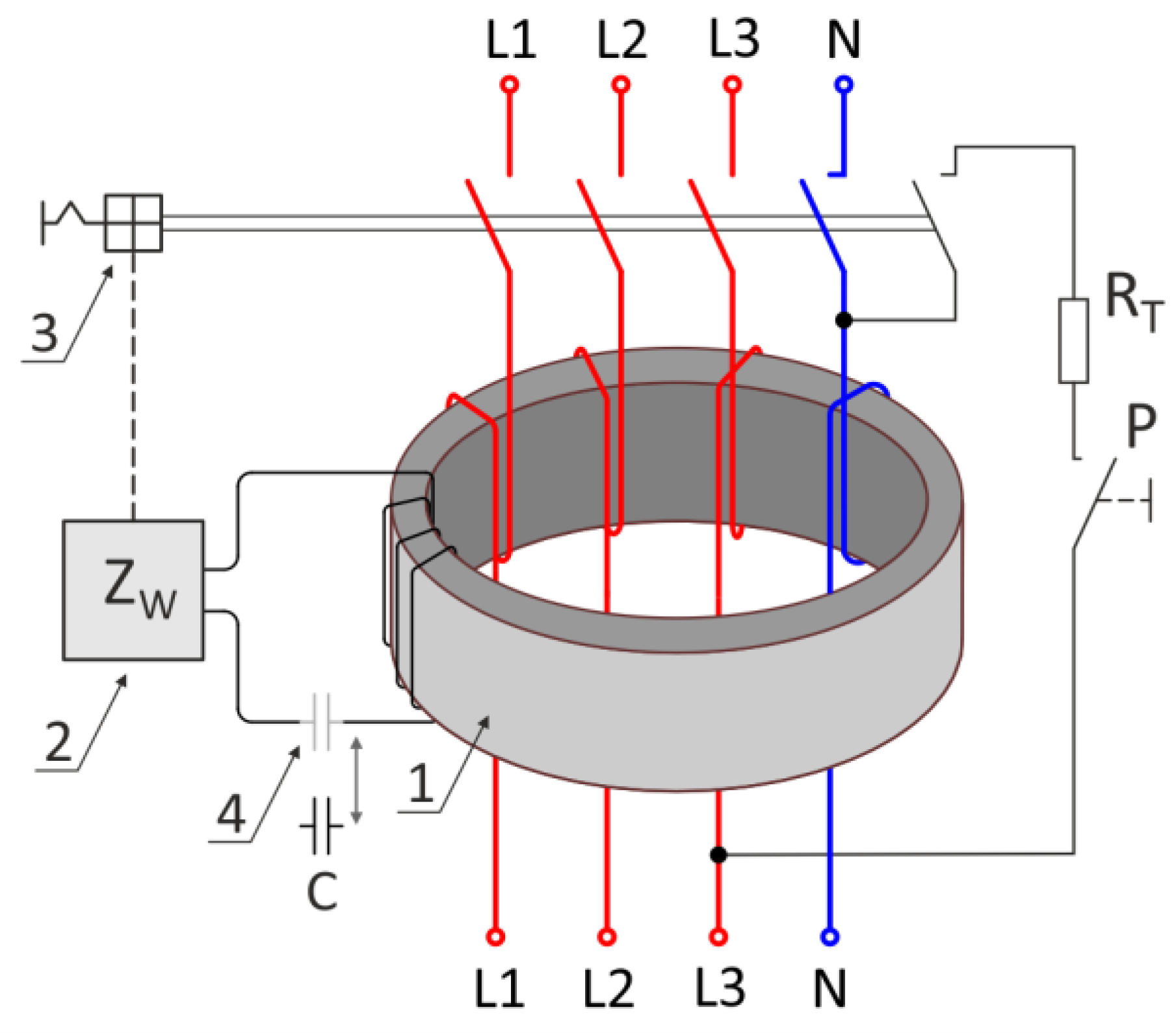
Figure 2.
The equivalent diagram of the summation current transformer which takes into account the influence of the error voltage on the transformation.
Figure 2.
The equivalent diagram of the summation current transformer which takes into account the influence of the error voltage on the transformation.

Figure 3.
Simplified equivalent diagram of the summation transformer for determining the impact of load matching.
Figure 3.
Simplified equivalent diagram of the summation transformer for determining the impact of load matching.

Figure 4.
Simplified equivalent diagram of the secondary circuit in the summation transformer which takes into account a series capacitor.
Figure 4.
Simplified equivalent diagram of the secondary circuit in the summation transformer which takes into account a series capacitor.
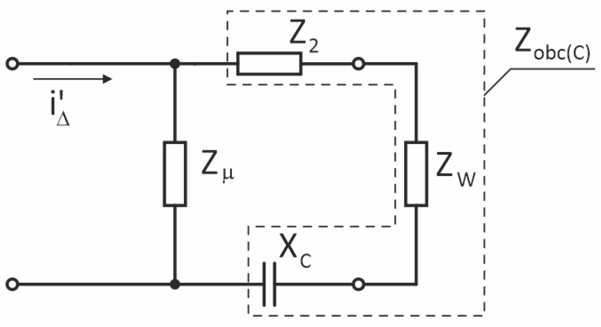
Figure 5.
Diagram of the system for measuring the break times and tripping currents of RCDs using the MRP-201 meter from SONEL.
Figure 5.
Diagram of the system for measuring the break times and tripping currents of RCDs using the MRP-201 meter from SONEL.

Figure 6.
Diagram of the measurement system (option 2) for determining the RCD break time for different initial phases of the differential current.
Figure 6.
Diagram of the measurement system (option 2) for determining the RCD break time for different initial phases of the differential current.

Figure 7.
Diagram of the internal structure of the tested circuit breakers: (a) RCD-1 and (b) RCD-2.
Figure 7.
Diagram of the internal structure of the tested circuit breakers: (a) RCD-1 and (b) RCD-2.

Figure 8.
Diagram of the internal structure of the tested circuit breakers: (a) RCD-3 and (b) RCD-4.
Figure 8.
Diagram of the internal structure of the tested circuit breakers: (a) RCD-3 and (b) RCD-4.

Figure 9.
Diagram of the internal structure of the tested circuit breakers: (a) RCD-5 and (b) RCD-6.
Figure 9.
Diagram of the internal structure of the tested circuit breakers: (a) RCD-5 and (b) RCD-6.

Figure 10.
Diagram of the internal structure of the tested circuit breakers: (a) RCD-7 and (b) RCD-8.
Figure 10.
Diagram of the internal structure of the tested circuit breakers: (a) RCD-7 and (b) RCD-8.

Figure 11.
Supply voltage (channel 1) and disconnection current (channel 2) vs. time for RCD-2 (Table 3), with an input of 30 mA (50 Hz) and measured break time of 35 ms.
Figure 11.
Supply voltage (channel 1) and disconnection current (channel 2) vs. time for RCD-2 (Table 3), with an input of 30 mA (50 Hz) and measured break time of 35 ms.

Figure 12.
Supply voltage (channel 1) and tripping current (channel 2) vs. time for RCD-2 (Table 4) and the input one-half sinusoidal with negative polarity.
Figure 12.
Supply voltage (channel 1) and tripping current (channel 2) vs. time for RCD-2 (Table 4) and the input one-half sinusoidal with negative polarity.

Figure 13.
Supply voltage (channel 1) and disconnection current (channel 2) vs. time for RCD-1, with an input of 30 mA (50 Hz), initial phase of 0°, and measured break time of 18 ms.
Figure 13.
Supply voltage (channel 1) and disconnection current (channel 2) vs. time for RCD-1, with an input of 30 mA (50 Hz), initial phase of 0°, and measured break time of 18 ms.

Figure 14.
Supply voltage (channel 1) and disconnection current (channel 2) vs. time for RCD-8, with an input of 30 mA (50 Hz), initial phase of 90°, and measured break time of 149 ms.
Figure 14.
Supply voltage (channel 1) and disconnection current (channel 2) vs. time for RCD-8, with an input of 30 mA (50 Hz), initial phase of 90°, and measured break time of 149 ms.

Figure 15.
The dependencies of RCD-1–5 break time versus initial phase of the test current (IΔ = 30 mA, 50 Hz).
Figure 15.
The dependencies of RCD-1–5 break time versus initial phase of the test current (IΔ = 30 mA, 50 Hz).

Figure 16.
The dependencies of RCD-6–8 break times versus initial phase of the test current (IΔ = 30 mA, 50 Hz).
Figure 16.
The dependencies of RCD-6–8 break times versus initial phase of the test current (IΔ = 30 mA, 50 Hz).

Figure 17.
The dependencies of RCD-8 break time versus initial phase of the test current (IΔ), for 30 mA, 60 mA, and 150 mA (50 Hz).
Figure 17.
The dependencies of RCD-8 break time versus initial phase of the test current (IΔ), for 30 mA, 60 mA, and 150 mA (50 Hz).


| Type | In | IΔn | Normalized Values of Break Time and Non-Break Time for Residual Current (IΔ) Equal to | |||
|---|---|---|---|---|---|---|
| IΔn | 2·IΔn | 5·IΔn | ||||
| General use | Any value | Any value | 0.3 s | 0.15 s | 0.04 s | Maximum break time |
| Selective | ≥25 A | >0.03 A | 0.5 s | 0.2 s | 0.15 s | Maximum break time |
| 0.13 s | 0.06 s | 0.05 s | Minimum non-break time | |||
Table 2.
List of technical parameters of RCDs subjected to laboratory tests.
| Notation | Kind | Type | IΔn | In | LB |
|---|---|---|---|---|---|
| RCD-1 (producer 1) | RCBO | A | 30 mA | B16 A | 2P |
| RCD-2 (producer 2) | RCBO | AC | 30 mA | C16 A | 4P |
| RCD-3 (producer 3) | RCCB | AC | 30 mA | 40 A | 2P |
| RCD-4 (producer 4) | RCCB | A | 30 mA | 25 A | 2P |
| RCD-5 (producer 5) | RCCB | AC | 30 mA | 25 A | 2P |
| RCD-6 (producer 6) | RCCB | A | 30 mA | 25 A | 4P |
| RCD-7 (producer 7) | RCCB | AC | 30 mA | 25 A | 2P |
| RCD-8 (producer 8) | RCCB | AC | 30 mA | 40 A | 4P |
Table 3.
A summary of break times for RCD circuit breakers measured with MRP-201 (sine excitation waveform of 50 Hz and initial phase 0°).
Table 3.
A summary of break times for RCD circuit breakers measured with MRP-201 (sine excitation waveform of 50 Hz and initial phase 0°).
| Notation | 1·IΔn | 2·IΔn | 5·IΔn | AUTO | |
|---|---|---|---|---|---|
| 30 mA | 60 mA | 150 mA | t | Measured IΔ | |
| RCD-1 | 27 ms | 10 ms | 8 ms | 27 ms | 19 mA |
| RCD-2 | 35 ms | 15 ms | 13 ms | 35 ms | 19 mA |
| RCD-3 | 27 ms | 10 ms | 8 ms | 27 ms | 19 mA |
| RCD-4 | 25 ms | 9 ms | 7 ms | 25 ms | 16 mA |
| RCD-5 | 27 ms | 10 ms | 8 ms | 27 ms | 20 mA |
| RCD-6 | 10–18 ms | 8 ms | 7 ms | 11 ms | 24 mA |
| RCD-7 | 8 ms | 6 ms | 5 ms | 9 ms | 22 mA |
| RCD-8 | 8–18 ms | 7 ms | 7 ms | 18 ms | 17 mA |
Table 4.
A summary of RCD break times obtained with MRP-201 meter for various shapes of test current excitations (50 Hz).
Table 4.
A summary of RCD break times obtained with MRP-201 meter for various shapes of test current excitations (50 Hz).
| Notation |  |  |  |  |
|---|---|---|---|---|
| 30 mA | 30 mA | 30 mA | 30 mA | |
| RCD-1 | 27 ms | 17 ms | 10 ms | 15 ms |
| RCD-2 | 35 ms | 26 ms | 15 ms | 28 ms |
| RCD-3 | 27 ms | 17 ms | 10 ms | 15 ms |
| RCD-4 | 25 ms | 16 ms | 9 ms | 14 ms |
| RCD-5 | 27 ms | 18 ms | 10 ms | 15 ms |
| RCD-6 | 17 ms | 17 ms | 7 ms | 8 ms |
| RCD-7 | 8 ms | 18 ms | 6 ms | No tripping |
| RCD-8 | 8 ms | 8 ms | 7 ms | No tripping |
Publisher’s Note: MDPI stays neutral with regard to jurisdictional claims in published maps and institutional affiliations. |
© 2022 by the author. Licensee MDPI, Basel, Switzerland. This article is an open access article distributed under the terms and conditions of the Creative Commons Attribution (CC BY) license (https://creativecommons.org/licenses/by/4.0/).
Share and Cite
MDPI and ACS Style
Czaja, P. Influence of the Design of a Residual Current Device on Its Break Time. Energies 2022, 15, 9054. https://doi.org/10.3390/en15239054
AMA Style
Czaja P. Influence of the Design of a Residual Current Device on Its Break Time. Energies. 2022; 15(23):9054. https://doi.org/10.3390/en15239054
Chicago/Turabian StyleCzaja, Pawel. 2022. "Influence of the Design of a Residual Current Device on Its Break Time" Energies 15, no. 23: 9054. https://doi.org/10.3390/en15239054
Note that from the first issue of 2016, this journal uses article numbers instead of page numbers. See further details here.