Article

An Underactuated Universal Gripper: Design, Analysis, and Experiment

1
School of Mechanical Engineering, Yanshan University, Qinhuangdao 066004, China
2
School of Mechanical Engineering, Tianjin Sino-German University of Applied Sciences, Tianjin 300350, China
3
School of Mechanical Engineering, Tianjin University of Science and Technology, Tianjin 300222, China
*
Author to whom correspondence should be addressed.
Energies 2022, 15(23), 9151; https://doi.org/10.3390/en15239151
Submission received: 20 August 2022 / Revised: 19 October 2022 / Accepted: 28 November 2022 / Published: 2 December 2022
(This article belongs to the Special Issue Vehicles Dynamics and Propulsion Technologies)

Abstract

:
As the working tool of the robot, the importance of the gripper becomes more prominent with the extensive use of the robot. This paper proposes a new type of underactuated universal gripper that can be applied to handle lightweight parts of any shape. It integrates a crank train and a four-bar mechanism to grasp objects. The kinematics and statics analysis of the proposed gripper were carried out; and in this paper, we briefly introduce the concept and control system design. Then, the motion characteristics and grasping ability of the underactuated gripper are presented. A prototype of the gripper was designed and manufactured based on the simulation analysis, and relevant grasping experiments were carried out. The experimental results verify that the proposed universal gripper has the advantages of safe design, easy manufacturing, effective gripping, and stable holding of objects.

1. Introduction

In recent years, the rapid development of robot technology has been widely applied in many fields such as industrial production, medical services, space development, national defense, and military affairs [1,2,3,4]. Robotic grippers, commonly referred to as “end effectors”, are attached to the end of a robotic manipulator [5,6]. Industrial robot grippers play a key role in modern automation. High-performance grippers can provide robots with more precise and stable grasping capabilities, expanding the application fields of robots. In addition, grippers must be able to perform tasks under demanding requirements during the manufacturing process, due to handling operations [7,8]. In order to adapt to increasingly complex and diverse operating environments, robotic grippers are required to have greater flexibility and adaptability to perform stable grasps and manipulations in unstructured environments.
Inspired by the grasping motion of human hands, dexterous hands are designed to imitate human fingers in order to grasp objects of different shapes [9]. Fully actuated humanoid dexterous hands represented by MIT hand [10], cyber hand [11], DLR hand [12], DLR hand II [13], and Robonaut hand [14] have been developed, and they can stably complete the grasping tasks. However, with the increase in dexterous hand-driving elements, complex control strategies, and relatively poor reliability, the practical application of fully actuated humanoid dexterous hands is limited to a certain extent. Underactuated methods are widely used in the design of manipulators [15,16] or grippers [17] because they can realize various grasping tasks in by coupling with a small number of driving sources, and they have better performance. Moreover, they have the advantages of adaptability, grasping range, grasping ability, and a simple control strategy. Therefore, the study of underactuated dexterous hands has become a prominent topic in the field of dexterous hands over the past few years [18,19]. Many achievements have been made, such as Bistable Gripper [20], Washington Hand [21], Pisa/IIT Soft Hand [22,23], Robonaut2 Hand [24], POLYPUS Gripper [25], UADH, DLR-HIT II Robot Hand [26].
Nevertheless, in the study of underactuated dexterous hands, tendon actuation or cable actuation is commonly used [27,28,29]. Although these two structures improve the grip force to a certain extent, they not only reduce the working space, load capacity, accuracy, stiffness, and stability of the dexterous hand, but also cause problems regarding low precision of movement and complicated control; furthermore, the use of springs or other elastic components limits the important function of the bidirectional bending of the robotic gripper. In addition, the underactuated manipulators generally have relatively single grasping motions and functions which limit the ability of fingers to grasp objects, making them limited in realizing complex humanoid grasping. The following Table 1 lists the advantages and disadvantages of typical gripper structure design.
In view of these limitations, we proposed a novel type of underactuated universal gripper which performs the grasping of different objects under various grasping postures, including fingertip grasping and palm-enveloping grasping, through the coordinated motion of multiple fingers. Moreover, the gripper must have good adaptability and a strong grasping ability. In order to achieve these goals, a crank train and a four-bar mechanism were adopted to achieve the coupled motion of finger phalanges. Furthermore, a motor was used to drive a single finger to rotate 90° to fulfill the requirement of the adaptive grasping. Meanwhile, the proposed gripper has the advantages of simple structure, strong universality, easy manufacturing, reliable structural stiffness, high transmission efficiency, effective gripping and stable gripping of objects, which is expected to be an applicable grabbing scheme in the food industry, intelligent manufacturing, the pharmaceutical industry, and other related domains. The main contributions of this study are as follows: (1) A new type of underactuated universal gripper was designed and fabricated. (2) The concept and control system of the underactuated universal gripper were presented, and the kinematics and statics of object grasping were analyzed. (3) The effectiveness of the grasping ability of the underactuated universal gripper was verified through experiments.
The rest of this paper is organized as follows: the design of the underactuated universal gripper is introduced, including the function, structure, parameters, and control system in Section 2. Section 3 reports the kinematics analysis of the underactuated universal gripper and the static analysis of the multi-finger grasping object. In Section 4, the designed underactuated universal gripper is simulated and analyzed, and the grasping performance is verified by experiments. Section 5 presents the conclusions of this study.

2. Development of Underactuated Universal Gripper

2.1. Structural Design of Mobile Robot

Figure 1 presents the mechanical structure of the proposed mobile robot, which was divided into five modules, including a mobile platform, robotic arm, underactuated universal gripper, control module, and sensor module. The mobile platform adopted four-wheel drive to realize multi-terrain movement. The robotic arm had four degrees of freedom, and the motion of the camera and gripper was controlled by servo motors. The underactuated universal gripper simulated the humanoid design—which was composed of three fingers with the same structure at an included angle of 120 degrees—and the multi-fingers were driven by a motor to grasp different objects cooperatively. The geometric parameters and attributed parameters of the main equipment in the proposed mobile robot are listed in Table 2.

2.2. Structure and Working Principle

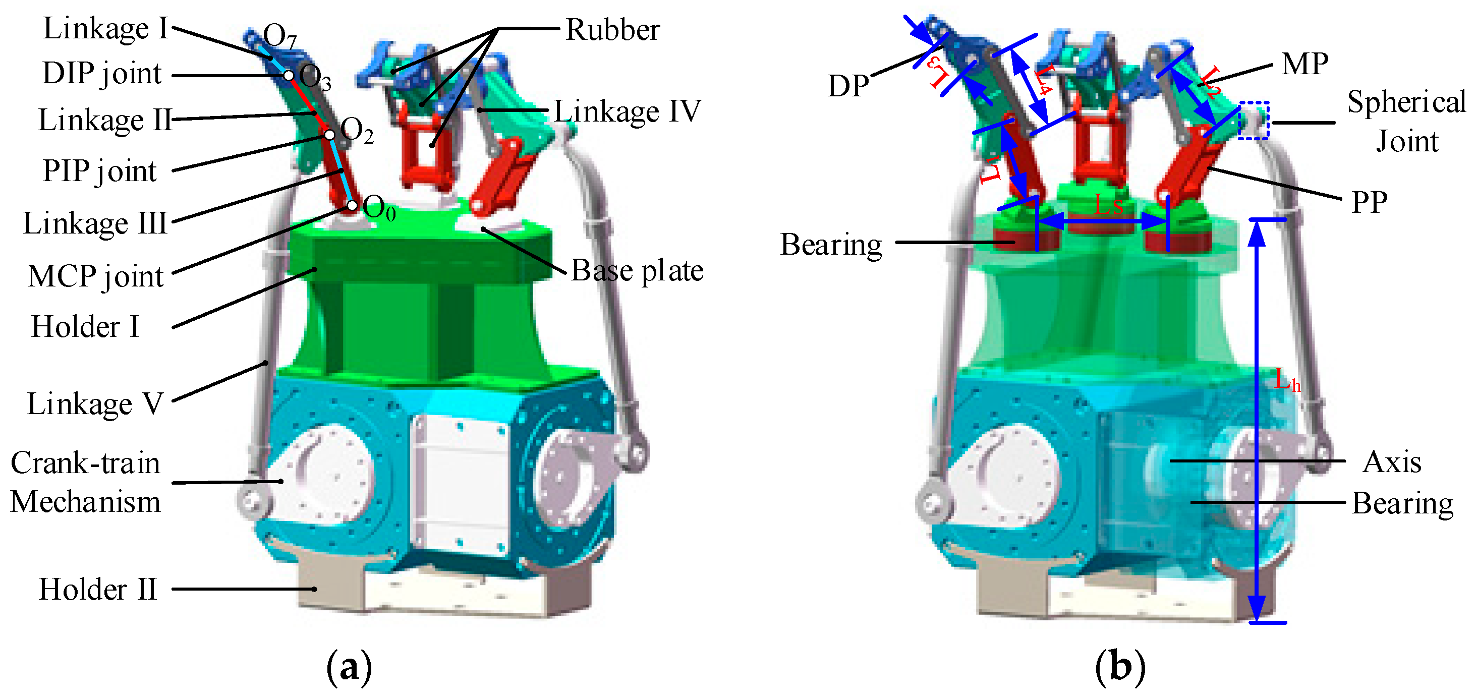
Figure 2 shows the underactuated universal gripper, which is the focus of this paper. Because the number of actuators of the underactuated gripper is far less than its number of degrees of freedom [44], a suitable transmission strategy is required to achieve humanoid motion. Linkage [45,46], belt [47], and tendon/cable drives were used in the mechanism design as common transmission schemes. In this study, in order to ensure the good force transmission performance, grasping strength, and stability of the underactuated gripper, a transmission mode based on a crank train and four-bar mechanism was proposed; the motor drive mode, with the advantages of small volume, convenient control, and large output force, was adopted in order to realize the stable grasp of objects of arbitrary shape in the unstructured environment. As shown in Figure 2, the structure of the gripper was primarily composed of three rigid–flexible coupling fingers, each of which was composed of three phalanxes. O0 O2, O2 O3, and O3 O7 are the proximal phalanx (PP), middle phalanx (MP) and distal phalanx (DP) of the finger, respectively. O0, O2, and O3 represent the metacarpophalangeal (MCP) joint, proximal interphalangeal (PIP) joint, and distal interphalangeal (DIP) joint, respectively. The inferior extremity of linkage I was connected with holder I through the MCP joint (rotating shaft), and the superior extremity was connected with linkage II and linkage III through the PIP joint (rotating shaft) and linkage IV, respectively. Linkage II was connected with linkage I and linkage III to form a four-bar mechanism; meanwhile, it connected with the crank mechanism through the spherical hinge, and the object was enveloped or grasped by driving the crank train mechanism. In addition, the groove inside each linkage was filled with flexible material. In this paper, silicone rubber was selected as the material of the flexible joint. Unlike humanoid fingers, each finger in the underactuated universal gripper could rotate 90 degrees through DC motor drive and complete single finger, two finger, and multiple finger coordinated movements, according to the task requirements. The gripper could freely change the working mode, which greatly improved its environmental adaptability.
The working principle of the underactuated universal gripper is described as follows.
(1)
The camera locates the target object, and the robotic arm drives the gripper to approach the target object.
(2)
According to the shape recognition results of the target object, the relative position and posture of the three fingers in the gripper are adjusted by the DC motor drive.
(3)
Driven by the DC motors, the crank train mechanisms drive the four-bar mechanisms to move, and the phalanx moves to the center and contacts the surface of the object.
(4)
The motor continues to drive until the gripper stably grabs the object. Finally, the object handling is achieved due to the movement of the robotic arm.

2.3. Gripper Parameter Setting

In the design of the structural parameters of the gripper, we considered the conditions of structural compactness, coordination, and anti-interference, and referred to the structural size of human fingers and the size range of the grasping object [48]. The geometric parameters of the proposed underactuated gripper and the attribute parameters are shown in Figure 2b and Table 3.

2.4. Control System Design

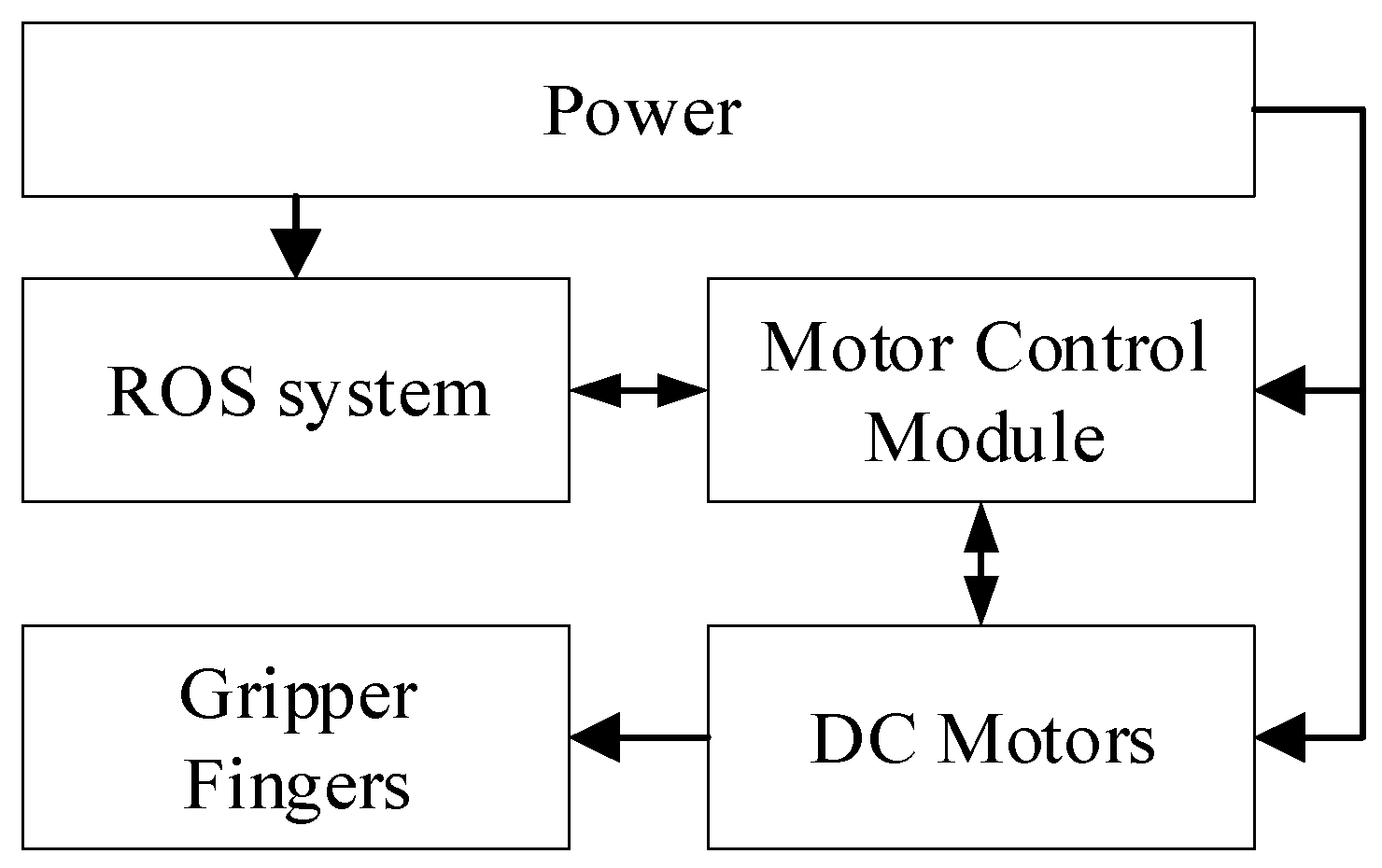
The universal gripper had three fingers, each of which was an independent drive source, and each finger could carry out a separate rotation movement; consequently, six motors were required. The control hardware scheme of the proposed universal gripper is shown in Figure 3. The control board was composed of an ROS application program, a microcontroller, and a motor control module. The ROS application is for the operator to give commands [49]. The microcontroller handles the events and the commands. It communicates with the motor control module through the port. Then, the motor control module can selectively drive the DC motor through PWM method to achieve the gripping motions of the gripper. The modularized design of the control panel ensures that each motor operation mode is independent, not affecting the normal operation of other control circuits.

3. Performance Analysis of Gripper

In order to better illustrate the geometric features of the gripper, the target object was treated as spherical, and all the components of the gripper were considered as rigid bodies in the analysis.

3.1. Grasping Process

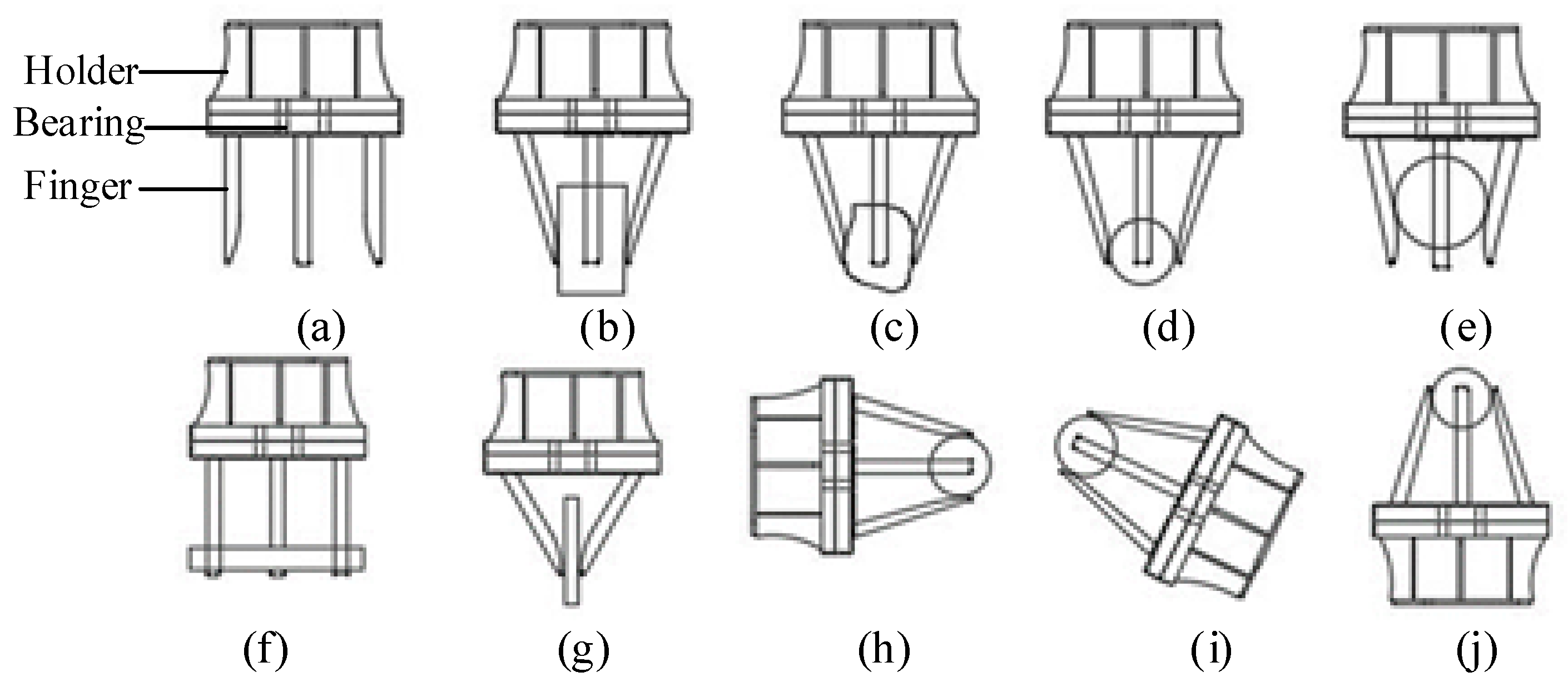
As one of the most important components of a mobile robot, the underactuated gripper is mainly designed to grasp objects of various shapes, sizes, and orientations. Three fingers, six motors, and a holder were integrated in the gripper; all motors were integrated inside the holder, and the fingers were installed on the holder by bearings, as shown in Figure 4a.
Different grasping strategies should be selected for objects of different shapes and sizes. For cuboid objects, the gripper can adjust the posture between three fingers to grasp them (Figure 4b,f) or it can choose two fingers to grasp them (Figure 4g). For small objects, the gripper can grasp them with three fingertips (Figure 4d). For large objects, the gripper can adopt envelope gripping (Figure 4e). For complex objects, the fingers can be driven by the motors to adjust the angle to fit the surface of the object (Figure 4c). At the same time, the gripper can grasp the object from different angles (Figure 4h–j).
Within the gripper, the coupled motions of finger phalanxes are driven by motors to grasp objects of different shapes. It is also possible to adjust the posture of a single finger and the space between fingers to help grip objects.

3.2. Kinematic Analysis

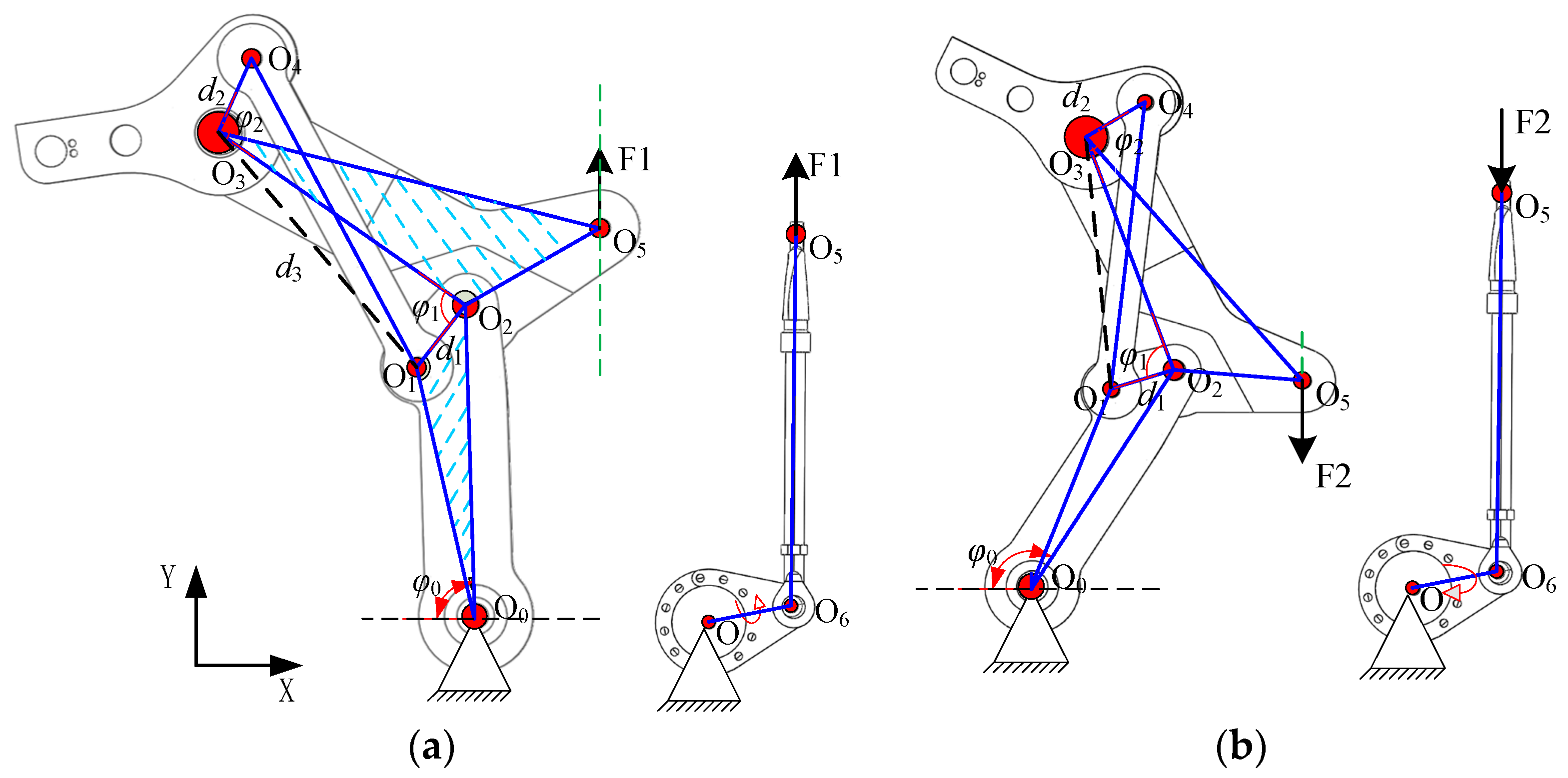
Since the structures of the three fingers in the universal gripper were identical, in the analysis, a single finger was considered an example for kinematic analysis; the mechanism diagram of the finger is shown in Figure 5. According to the rotation orientation of the crank, the motion of the gripper was divided into two processes: grasping and releasing. We defined that linkage IV was fixed to linkage I and linkage III, and its fixed center points were O4 and O1, respectively; linkage V and linkage II were fixed at point O5 through hinged joints, and the direction of motion was along the Y axis. The distance between O1 and O2 was d1, the distance between O3 and O4 was d2, the distance between O1 and O3 was d3, and the distances between PP, MP, and DP were L1, L2, and L3, respectively.
For the initial state, ∠O1O2O3 = α, and ∠O2O3O4 = β. So φ1α is the rotation angle of linkage II relative to linkage I, and φ2β is the rotation angle of linkage III relative to linkage II. If the crank rotates counterclockwise (Figure 5a), the hinge point O5 moves upward along F1 under the action of the force, and linkage III drives linkage I and linkage II to rotate counterclockwise around the point O0. When the connecting line between O2 and O0 is parallel to F1, that is, φ0 = 90°, linkage III is at the dead center position; subsequently, under the action of force, it will drive linkage I and linkage II to move counterclockwise around the points O3 and O2, respectively. At this time, the fingers were in the grasping process, and vice versa for the releasing process (Figure 5b).
As shown in Figure 6, we can calculate:
φ 2 = O 1 O 3 O 4 O 1 O 3 O 2
O 1 O 3 O 4 = arccos ( d 2 2 + d 3 2 L 4 2 2 d 2 d 3 )
O 1 O 3 O 2 = arccos ( L 2 2 + d 3 2 d 1 2 2 L 2 d 3 )
d 3 = d 1 2 + L 2 2 2 d 1 L 2 cos φ 1
The functional relationship between φ 2 and φ 1 is established through Equations (1)–(4), expressed as:
φ 2 = f ( φ 1 )
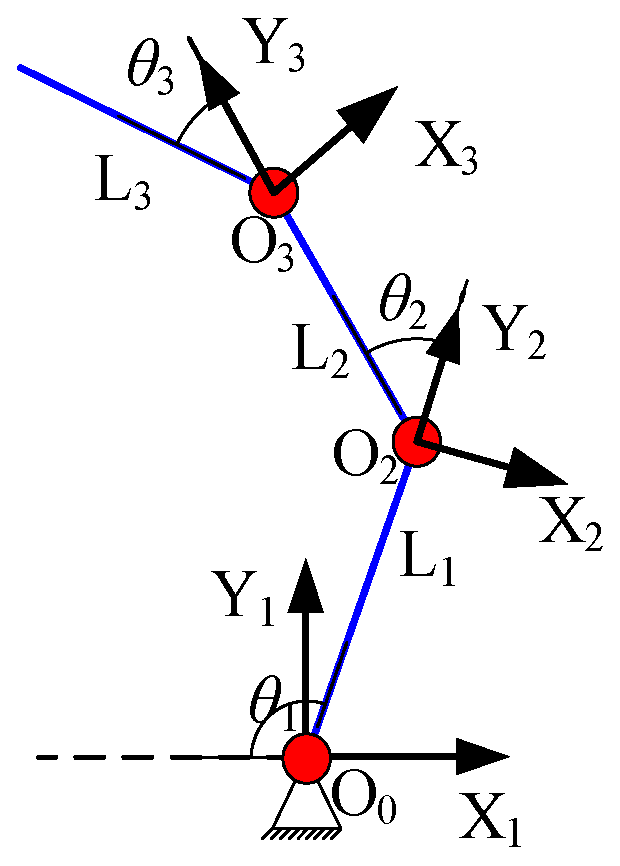
In the kinematic analysis of the gripper mechanism, the rotation of the finger itself was ignored, and the coordinate system model of the finger mechanism was simplified [50], as shown in Figure 6.
In Figure 6, Li is the length of linkage i, and i = 1, 2, 3. di denotes the distance of the connected joints from Xi−1to Xi, along with the Zi axis. αi denotes the coupler angle from Zi−1 to Zi, forward about the Xi−1 axis (torsion angle of linkage i). θi denotes the joint angle from Xi−1 to Xi, forward about the Zi axis (rotation angle between linkage i − 1 and linkage i). The D–H parameters of the finger are shown in Table 4.
The homogeneous transformation matrix between two adjacent connecting rods is expressed as
T i i 1 = [ cos θ i sin θ i cos α i sin θ i sin α i L i cos θ i sin θ i cos θ i cos α i sin α i cos θ i L i sin θ i 0 sin α i cos α i d i 0 0 0 1 ]
Therefore, the coordinates of point O7 on linkage I in the basic coordinate system X1Y1Z1 are expressed as
[ x y z 1 ] T = [ L 1 c 1 + L 2 c 12 + L 3 c 123 L 1 s 1 + L 2 s 12 + L 3 s 123 0 1 ]
where θ2 = φ1, θ3 = φ2, c 1 = cos θ 1 , s 1 = sin θ 1 , c 12 = cos ( θ 1 + θ 2 ) , s 12 = sin θ 1 + θ 2 , c 123 = cos ( θ 1 + θ 2 + θ 3 ) , and s 123 = sin ( θ 1 + θ 2 + θ 3 ) .

3.3. Static Analysis

When the gripper contacts the object, the interacting force and torque are generated between the finger and the object. The condition for stable grasping is that the resultant force acting on the object is 0 [51]. We supposed that the coordinates of point O7 were (x, y). According to Equation (7), the position relative to the joint variable ( θ 1 , θ 2 , θ 3 ) can be expressed as:
{ x = L 1 c 1 + L 2 c 12 + L 3 c 123 y = L 1 s 1 + L 2 s 12 + L 3 s 123
We differentiated Equation (8) and converted it into a matrix:
[ d x d y ] = [ x θ 1 x θ 2 x θ 3 y θ 1 y θ 2 y θ 3 ] [ d θ 1 d θ 2 d θ 3 ] = J [ d θ 1 d θ 2 d θ 3 ]
where J is the velocity Jacobian matrix of the gripper.
Equation (9) can be simplified as
d X = J d θ
The Jacobian matrix J is determined by Equations (5), (8) and (9).
During the gripper grasping process, there is no displacement of the force acting on the object. Based on the principle of virtual work [52], the balance equation is expressed as
τ = J T F
where τ represents joint torque. F indicates the contact force between linkage I and the object.
In application, the torque of each joint can be calculated according to the force measured by the sensor.
Figure 7a shows the gripper adopting three fingers symmetrically grasping the ball. As the four fingers were uniformly placed on the circumference and each finger has the same structure, only one finger was modeled, as shown in Figure 7b.
We defined the center coordinates O (x0, y0) of a spherical object with a radius of r. The coordinates of the contact points were A (x1, y1) and B (x2, y2), respectively. The contact forces of the phalanx were F1 and F2. During the gripper stable grasping process, a stable system satisfying static balance was formed between the fingers and the object. At this time, the vertical coordinate of point A and point O can be expressed as Equation (12) and Equation (13), respectively.
y 1 = x 1 cot θ 2 L 1
y 0 = y 1 r 2 ( x 1 x 0 ) 2
When grasping the envelope, the contact points of the fingers are tangent to the surface of the object. Therefore, we can ascertain
θ 3 = π 2 arctan r L B
L B = ( x 1 + L 2 sin θ 2 ) 2 + ( y 1 L 2 cos θ 2 ) 2
L A = L 2 L B
where LA and LB represent the distance from contact points A and B to PIP joint (O2) and DIP joint (O3), respectively.
According to the principle of virtual work and the condition of static equilibrium, the joint torque can be described by
τ 1 = F 1 L A + F 2 ( L B + L 2 cos θ 3 ) τ 2 = F 2 L B
Moreover, the transpose of the Jacobian matrix can be obtained as follows
J T = [ L A L B + L 2 cos θ 3 0 L B ]
Based on the actual grasp of the finger and the object itself, the static balance equations are:
{ F 2 sin ( π 2 θ 2 + θ 3 ) + F 1 cos θ 2 [ F 2 sin ( π 2 θ 2 + θ 3 ) + F 1 cos θ 2 ] [ F 2 sin ( π 2 θ 2 + θ 3 ) + F 1 cos θ 2 ] = 0 F 2 cos ( π 2 θ 2 + θ 3 ) F 1 sin θ 2 + [ F 2 cos ( π 2 θ 2 + θ 3 ) F 1 sin θ 2 ] + [ F 2 sin ( π 2 θ 2 + θ 3 ) F 1 sin θ 2 ] = 0
where F 1 , F 2 , F 1 , and F 2 represent the force on the other two fingers, respectively.
If the gripper adopts two fingers symmetrically grasping the small ball, the analysis process is the same as the above; however, the forces of one finger need to be removed. Now, the static equilibrium equations are expressed as
{ F 2 sin ( π 2 θ 2 + θ 3 ) + F 1 cos θ 2 [ F 2 sin ( π 2 θ 2 + θ 3 ) + F 1 cos θ 2 ] = 0 F 2 cos ( π 2 θ 2 + θ 3 ) F 1 sin θ 2 + [ F 2 cos ( π 2 θ 2 + θ 3 ) F 1 sin θ 2 ] = 0
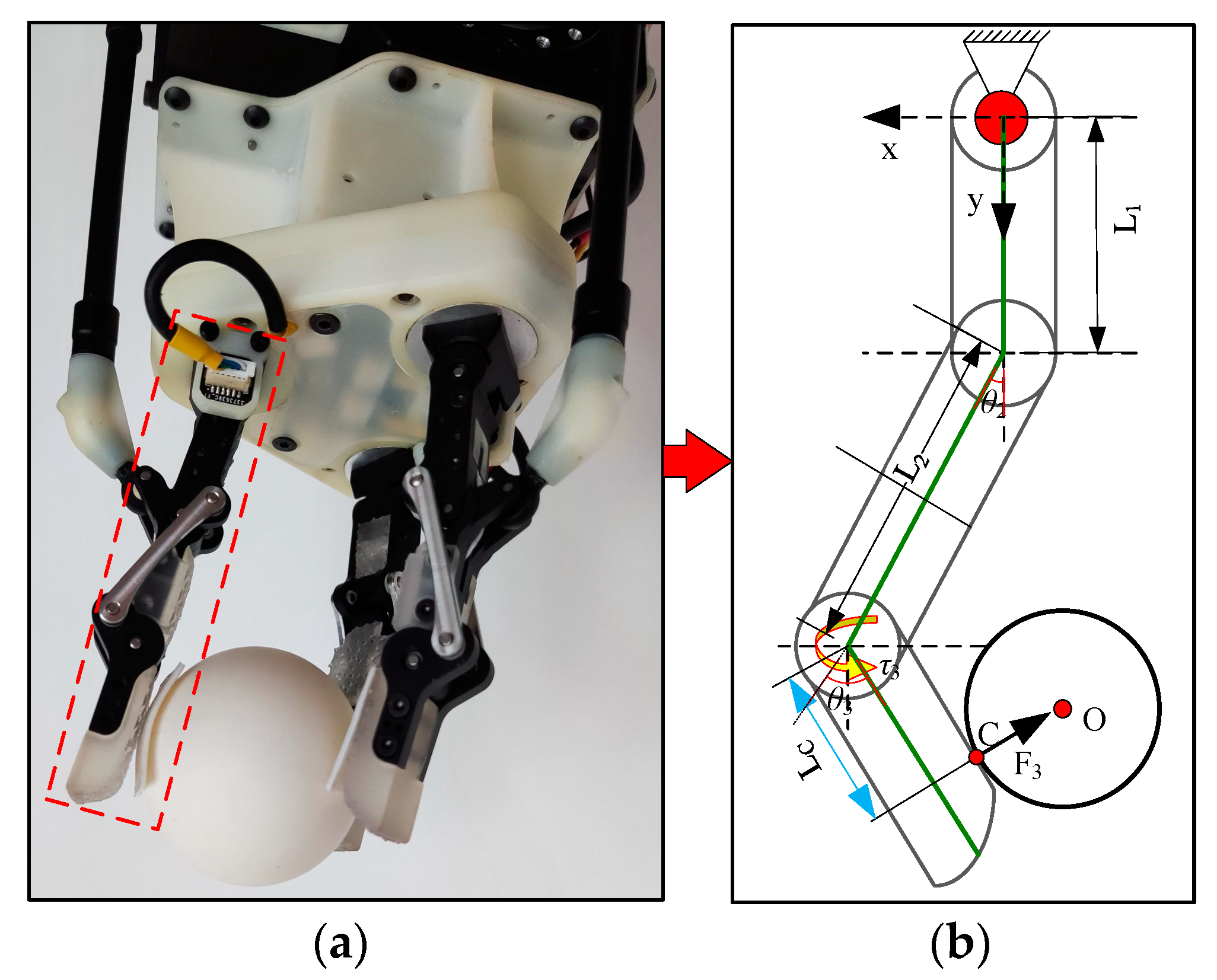
Compared with Figure 7a, Figure 8a shows that only the distal phalanx of the finger was used to grasp the ball (three fingers symmetrically pinching the ball), and the grasping force and motion in this case are shown in Figure 8b. C is the contact point. O is the center of the ball, and its radius is R.
The analysis process is the same as above. We can obtain the joint torque, the transpose of Jacobian matrix, and the static equation as follows:
τ 3 = F 3 L C
J T = [ 0 0 0 L C ]
{ F 3 sin ( π 2 θ 2 + θ 3 ) F 3 sin ( π 2 θ 2 + θ 3 ) F 3 sin ( π 2 θ 2 + θ 3 ) = 0 F 3 cos ( π 2 θ 2 + θ 3 ) + F 3 cos ( π 2 θ 2 + θ 3 ) + F 3 sin ( π 2 θ 2 + θ 3 ) = 0
where F 3 and F 3 represent the force on the other two fingers, respectively.

4. Simulation and Experiment

In order to accurately analyze the relevant performance of the universal gripper, motion analysis, finite element analysis and relevant grasping experiments were carried out.

4.1. Motion Simulation

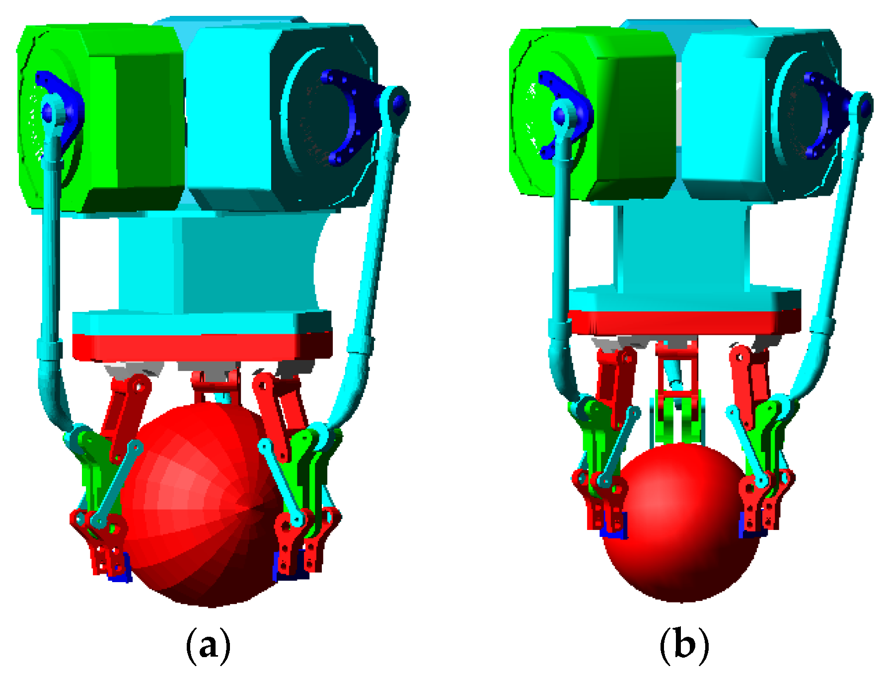
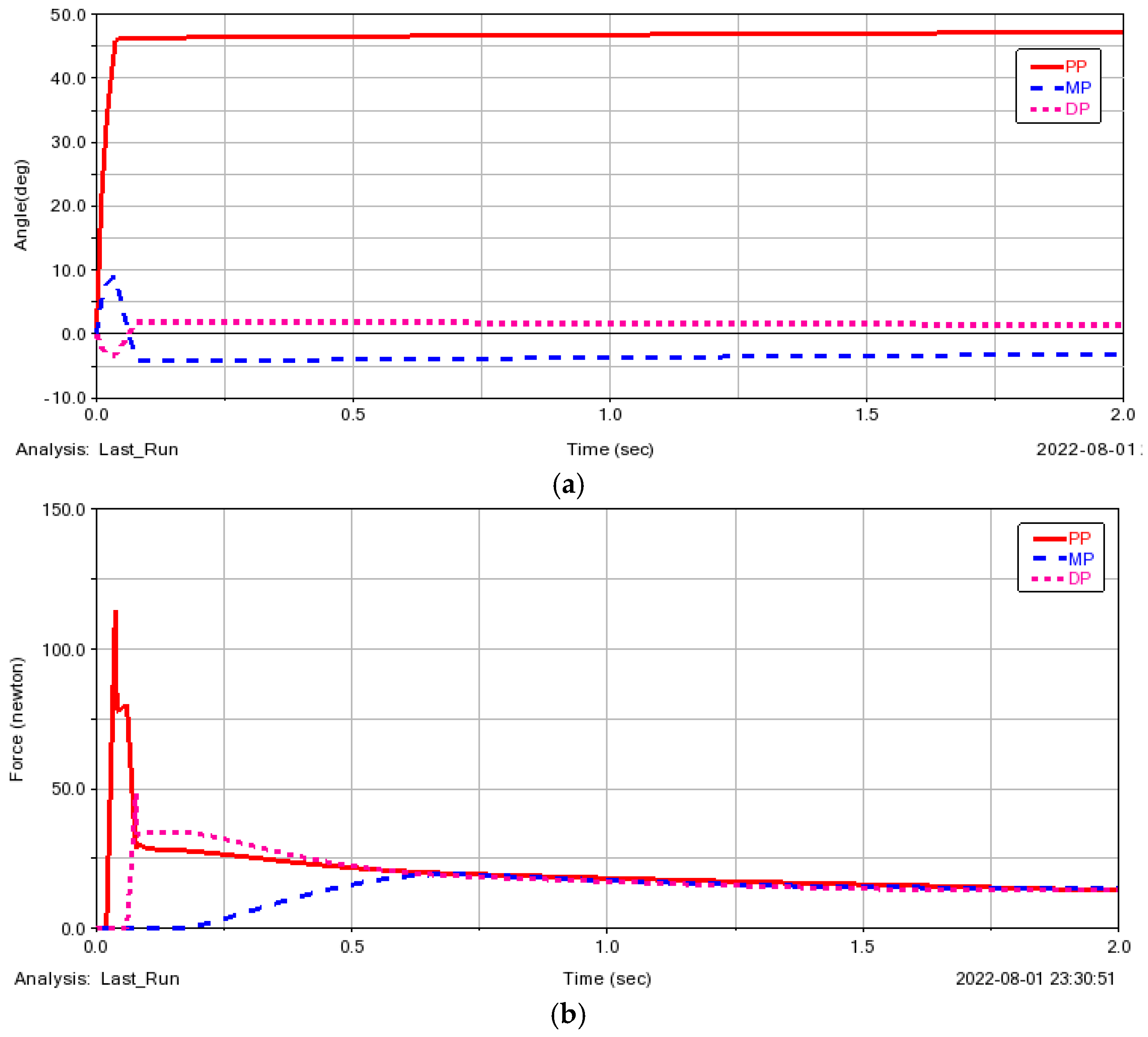
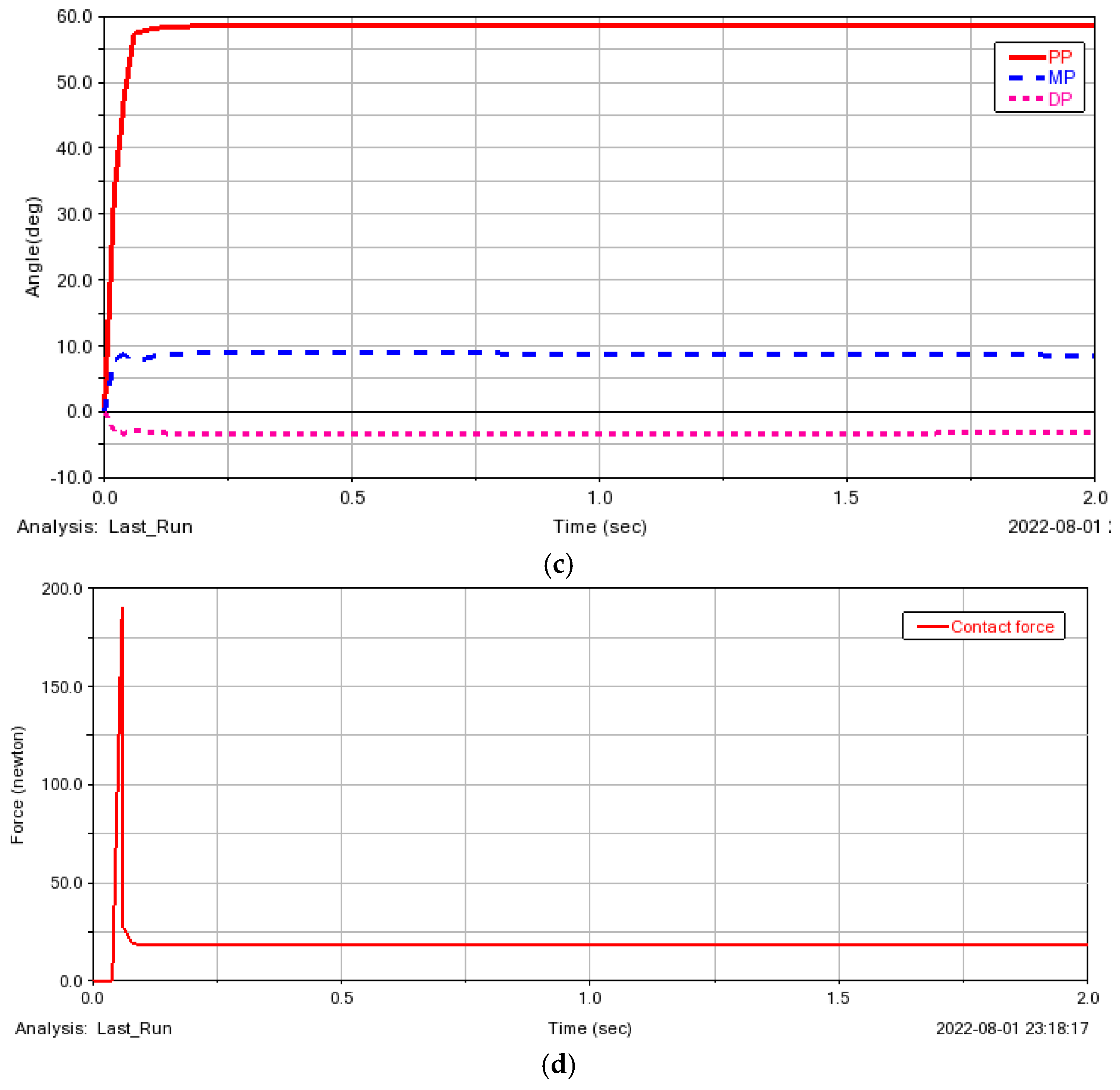
In the process of the gripper motion simulation, the underactuated general gripper adopted two grasping methods (see Figure 7a and Figure 8a) to grasp the spherical object (mass) and analyze its motion characteristics. The simulation process of the gripper grabbing a sphere is shown in Figure 9. Figure 10 shows the change in the contact force and rotation angle of each phalanx with time during the grasping simulation. The rationality of the virtual prototype model of underactuated universal gripper in realizing different grasping functions was verified by grasping simulation experiments.

4.2. Statics Simulation

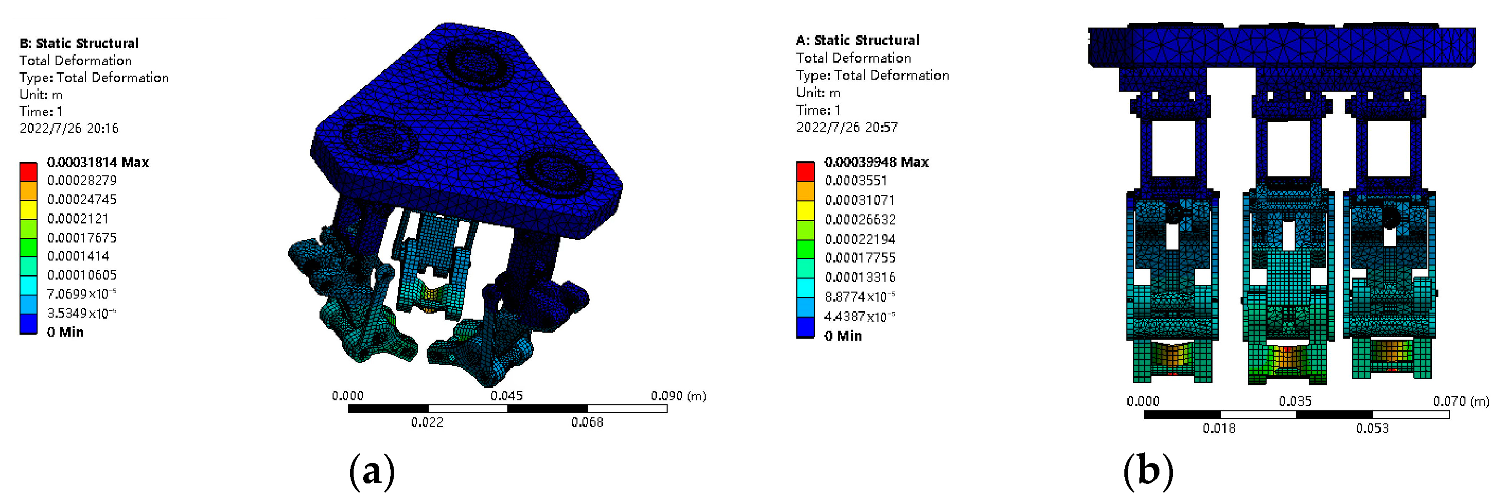
When objects of different sizes, shapes, and angles are grasped, the stress conditions of each finger differ. According to the literature [53,54], we set the properties of the gripper, including material (aluminum alloy), density (2.8 g/cm3), modulus of elasticity (70 Gpa), Poisson’s ratio (0.3), ultimate strength (320 MPa), and load (1 kg); then, we set the constraint boundary conditions in the finite element model. The stress conditions of the gripper when grasping the same object in different grasping methods are listed in Figure 11. Figure 12 displays the results of the finite element analysis of the gripper.
From the deformation cloud and stress cloud of the gripper listed, it can be seen that the maximum equivalent stress of the gripper is 251.62 MPa, which is less than the stress strength of the material itself. The maximum deformation is 0.399 mm. The structural shape variable is very small, meeting the design requirements of the mechanism. In other words, the structural design of the finger is stable and reliable, and can meet the mechanical performance of the gripper.

4.3. Universal Gripping Test of Gripper

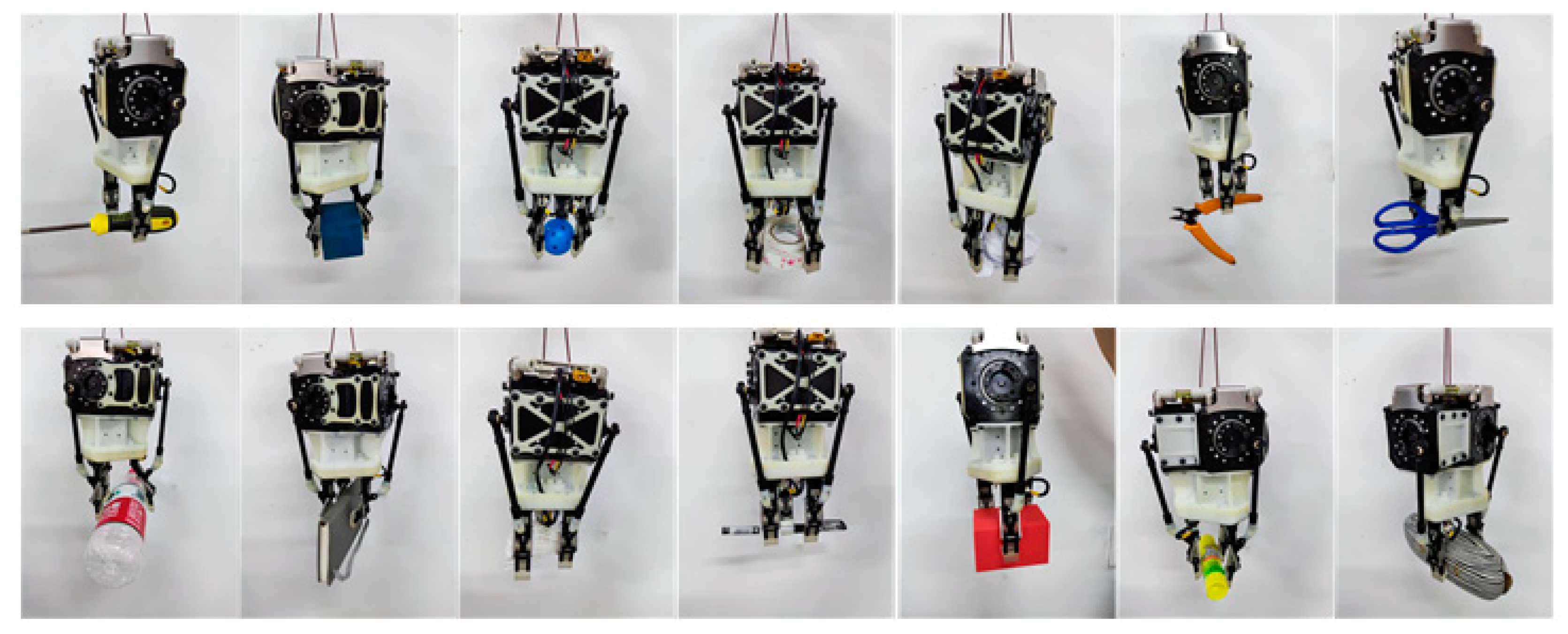
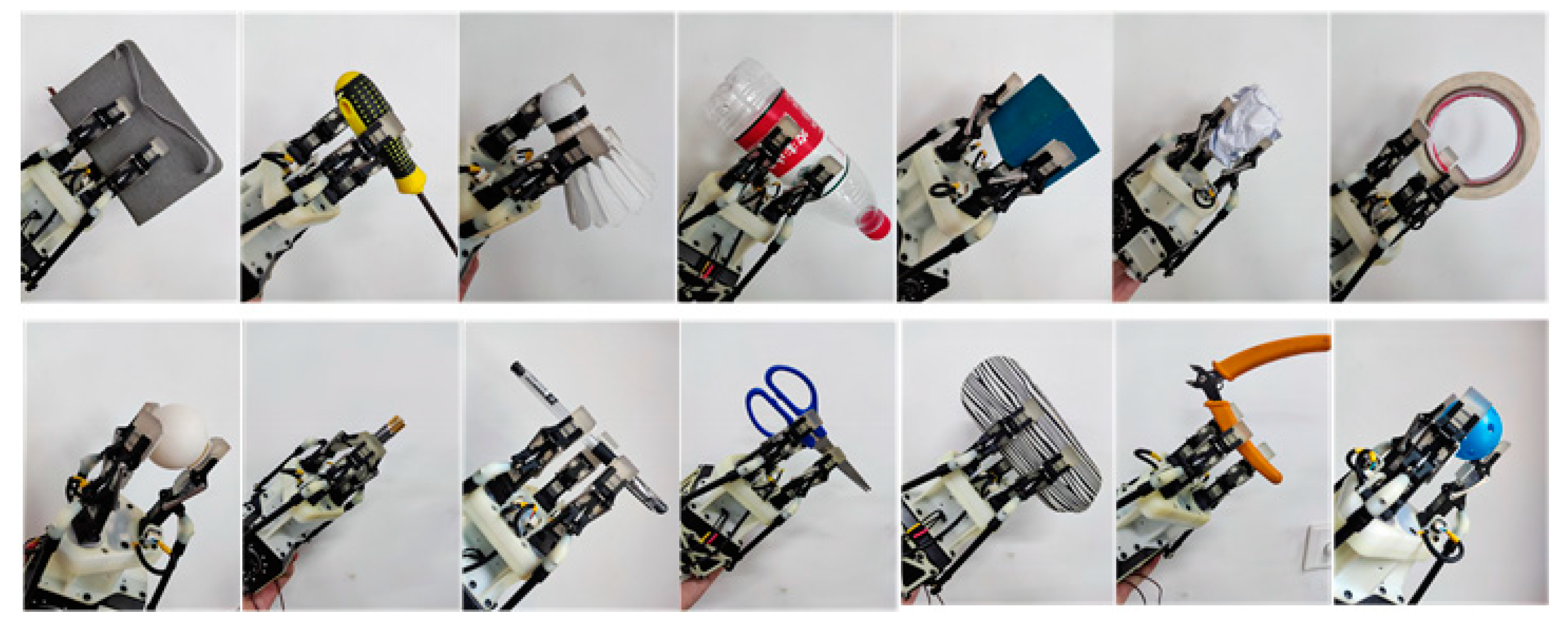
In order to verify the grasping function of the gripper, grasping tests were carried out for objects of different shapes and sizes. Through several grasping experiments, we saw that the proposed gripper could hold objects of different shapes and sizes using different grasping methods, as shown in Figure 13. At the same time, the gripper could grasp objects in all directions, as shown in Figure 14. Therefore, the versatility and adaptability of the proposed universal gripper, in grasping objects of various shapes, sizes, and orientations, were verified.
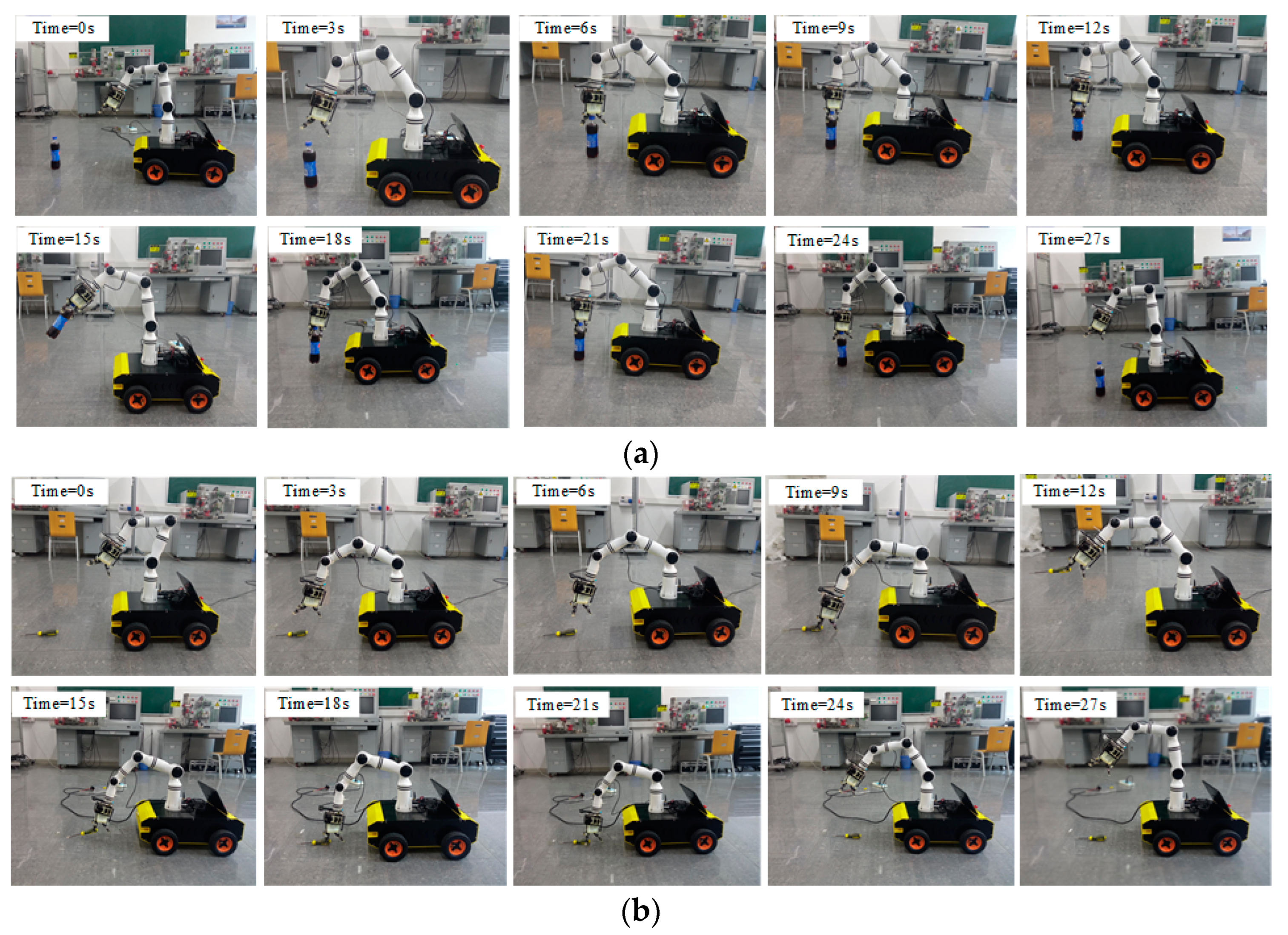
In order to further verify the gripping performance of the gripper, the underactuated universal gripper was installed at the end of the robotic arm; subsequently, the experiments of three fingers grasping a 0.5 kg cylindrical bottle and two fingers grasping a 0.1 kg screwdriver were carried out, respectively, as shown in Figure 15. The camera was used to locate the object, and the manipulator drove the underactuated universal gripper to grasp and carry the target object. The whole process was divided into the following four stages.
(1)
Time = 0–3 s, the mobile robot moved and located the target object by the camera.
(2)
Time = 3–9 s, we controlled the gripper motor action, and adjusted the gripper to the appropriate position and attitude to successfully grasp the target object.
(3)
Time = 12–24 s, the mobile robot reached the target area, and the target object was placed through cooperation between the camera, the robotic arm, and the gripper.
(4)
Time = 24–27 s, the robotic arm was reset, and the handling task was completed.
From these two experiments, we can see that the proposed underactuated universal gripper easily handled objects with a weight of at least 0.1 kg in the two-finger grasping mode, and handled 0.5 kg in the three-finger grasping mode. Meanwhile, the gripper operated stably and reliably throughout the entire operation process. The proposed universal gripper with compact structure can grip objects of various shapes, sizes, and orientations, and has strong versatility and adaptability.

5. Conclusions

This paper presented a new type of underactuated universal gripper, which was driven by six DC motors independently. With the use of a crank train, four-bar linkage, and rotating motor, the gripper not only performed various grasping postures but also grasped objects of different shapes and sizes. We drew the following conclusions.
(1)
This new underactuated universal gripper integrated a crank train mechanism and a four-bar mechanism to achieve the grasp and release of objects accurately. Based on this, the structural design and control system design of this gripper were carried out.
(2)
In the kinematic analysis of the gripper, the spatial position of the distal phalanx of the gripper during movement was calculated; through ADMAS kinematics simulation, the changes in contact forces, joint angles, and joint torques under the two grasping modes of the gripper were revealed.
(3)
In the static analysis of the gripper, numerical calculation revealed the static balance conditions of the gripper in various grasping modes, and the deformation cloud and stress cloud of the gripper were obtained using ANSYS software.
(4)
A prototype of the proposed gripper was designed and manufactured based upon the simulation analysis, and the experimental results verified the effectiveness of the proposed gripper.

Author Contributions

Methodology, Y.Z.; Validation, J.Z.; Investigation, C.W. and J.X.; Data curation, B.X.; Writing—original draft, C.W.; Supervision, Y.Z. All authors have read and agreed to the published version of the manuscript.

Funding

This research was funded by the Tianjin special fund for technological innovation guidance grant number 21YDTPJC00260.

Data Availability Statement

Data in this paper are available from the corresponding authors upon request.

Conflicts of Interest

The authors declare no conflict of interest.

References

  1. Bartoš, M.; Bulej, V.; Bohušík, M.; Stanček, J.; Ivanov, V.; Macek, P. An Overview of Robot Applications in Automotive Industry. Transp. Res. Procedia 2021, 55, 837–844. [Google Scholar] [CrossRef]
  2. Yin, Z.; Li, Y. Overview of Robotic Grasp Detection from 2D to 3D. Cogn. Robot. 2022, 2, 73–82. [Google Scholar] [CrossRef]
  3. Yadav, A.; Prakash, A.; Kumar, A.; Roy, S. Design of Remote-Controlled Land Mine Detection Troops Safety Robot. Mater. Today Proc. 2022, 56, 274–277. [Google Scholar] [CrossRef]
  4. Chen, X.; Huang, H.; Liu, Y.; Li, J.; Liu, M. Robot for Automatic Waste Sorting on Construction Sites. Autom. Constr. 2022, 141, 104387. [Google Scholar] [CrossRef]
  5. Zhou, Y.; Luo, J.; Wang, M. Grasping Force Optimization for Dual-Arm Space Robot after Capturing Target Based on Task Compatibility. Adv. Space Res. 2022, 70, 1496–1511. [Google Scholar] [CrossRef]
  6. Patil, V.; Narnaware, T.; Gangwani, T.; Raykar, N.R. Development of Flexible Universal Gripper for Handling Light Weight Parts of Arbitrary Shape. Mater. Today Proc. 2020, 28, 2591–2598. [Google Scholar] [CrossRef]
  7. Zhang, B.; Xie, Y.; Zhou, J.; Wang, K.; Zhang, Z. State-of-the-Art Robotic Grippers, Grasping and Control Strategies, as Well as Their Applications in Agricultural Robots: A Review. Comput. Electron. Agric. 2020, 177, 105694. [Google Scholar] [CrossRef]
  8. Ross, S.; Korostynska, O.; Cordova-Lopez, L.E.; Mason, A. A Review of Unilateral Grippers for Meat Industry Automation. Trends Food Sci. Technol. 2021, 119, 309–319. [Google Scholar] [CrossRef]
  9. Wang, D.; Xiong, Y.; Zi, B.; Qian, S.; Wang, Z.; Zhu, W. Design, Analysis and Experiment of a Passively Adaptive Underactuated Robotic Hand with Linkage-Slider and Rack-Pinion Mechanisms. Mech. Mach. Theory 2021, 155, 104092. [Google Scholar] [CrossRef]
  10. Jacobsen, S.C.; Wood, J.E.; Knutti, D.F.; Biggers, K.B. The UTAH/MIT dexterous hand: Work in progress. Int. J. Robot. Res. 1984, 3, 21–50. [Google Scholar] [CrossRef]
  11. Carrozza, M.C.; Cappiello, G.; Micera, S.; Edin, B.B.; Beccai, L.; Cipriani, C. Design of a cybernetic hand for perception and action. Biol. Cybern. 2006, 95, 629–644. [Google Scholar] [CrossRef] [Green Version]
  12. Grebenstein, M.; Chalon, M.; Friedl, W.; Haddadin, S.; Wimböck, T.; Hirzinger, G.; Siegwart, R. The Hand of the DLR Hand Arm System: Designed for Interaction. Int. J. Robot. Res. 2012, 31, 1531–1555. [Google Scholar] [CrossRef]
  13. Borst, C.; Fischer, M.; Haidacher, S.; Liu, H.; Hirzinger, G. DLR Hand II: Experiments and Experience with an Anthropomorphic Hand. In Proceedings of the 2003 IEEE International Conference on Robotics and Automation, Taipei, Taiwan, 14–19 September 2003; pp. 702–707. [Google Scholar] [CrossRef]
  14. Chavdarov, I.; Georgiev, I.; Miteva, L.; Trifonov, R.; Pavlova, G. The Robonaut 2 Hand-Designed to Do Work with Tools. In Proceedings of the 2012 IEEE International Conference on Robotics and Automation, Chengdu, China, 5–8 August 2012; pp. 3425–3430. [Google Scholar] [CrossRef] [Green Version]
  15. Rojas, N.; Ma, R.R.; Dollar, A.M. The GR2 gripper: An underactuated hand for open-loop in-hand planar manipulation. IEEE Trans. Robot. 2016, 32, 763–770. [Google Scholar] [CrossRef]
  16. Sintov, A.; Morgan, A.S.; Kimmel, A.; Dollar, A.M.; Bekris, K.E.; Boularias, A. Learning a state transition model of an underactuated adaptive hand. IEEE Robot. Autom. Lett. 2019, 4, 1287–1294. [Google Scholar] [CrossRef]
  17. Kragten, G.A.; Baril, M.; Gosselin, C.; Herder, J.L. Stable precision grasps by underactuated grippers. IEEE Trans. Robot. 2011, 27, 1056–1066. [Google Scholar] [CrossRef]
  18. Kashef, S.R.; Amini, S.; Akbarzadeh, A. Robotic Hand: A Review on Linkage-Driven Finger Mechanisms of Prosthetic Hands and Evaluation of the Performance Criteria. Mech. Mach. Theory 2020, 145, 103677. [Google Scholar] [CrossRef]
  19. Liu, P.; Huda, M.N.; Sun, L.; Yu, H. A Survey on Underactuated Robotic Systems: Bio-Inspiration, Trajectory Planning and Control. Mechatronics 2020, 72, 102443. [Google Scholar] [CrossRef]
  20. Mouazé, N.; Birglen, L. Bistable Compliant Underactuated Gripper for the Gentle Grasp of Soft Objects. Mech. Mach. Theory 2022, 170, 104676. [Google Scholar] [CrossRef]
  21. Ma, T.; Yang, D.; Zhao, H. Grasping Analysis and Optimization Design of a New Type of Underactuated Manipulator Claw. Robot 2020, 42, 354–364. [Google Scholar]
  22. Chen, Y.; Zhang, Q.; Tian, Q. The Research Status of Underwater Multi-fingered Hands. Robot 2020, 42, 749–768. [Google Scholar]
  23. Xu, Y.; Xu, S.; Xu, X.; Zhao, C. Kinematics and Grasping Analysis of SHU-II Five finger Dexterous Hand. Chin. J. Sci. Instrum. 2018, 39, 30–39. [Google Scholar]
  24. Ding, X.L.; Wang, Y.C.; Wang, Y.B.; Xu, K. A Review of Structures, Verification, and Calibration Technologies of Space Robotic Systems for On-orbit Servicing. Sci. China Technol. Sci. 2021, 64, 462–480. [Google Scholar] [CrossRef]
  25. Maggi, M.; Mantriota, G.; Reina, G. Introducing POLYPUS: A Novel Adaptive Vacuum Gripper. Mech. Mach. Theory 2022, 167, 104483. [Google Scholar] [CrossRef]
  26. Li, C.X.; Fahmy, A.; Sienz, J. Development of a Neural Network-Based Control System for the DLR-HIT II Robot Hand Using Leap Motion. IEEE Access 2019, 7, 136914–136923. [Google Scholar] [CrossRef]
  27. Martin, J.; Grossard, M. Design of a Fully Modular and Backdrivable Dexterous Hand. Int. J. Robot. Res. 2014, 33, 783–798. [Google Scholar] [CrossRef]
  28. Li, S.; Ma, X.; Liang, H.; Gorner, M.; Rupple, P.; Fang, B.; Sun, F.; Zhang, J. Vision-Based Teleoperation of Shadow Dexterous Hand Using End-to-End Deep Neural Network. In Proceedings of the 2019 International Conference on Robotics and Automation (ICRA), Montreal, QC, Canada, 20–24 May 2019; pp. 416–422. [Google Scholar] [CrossRef] [Green Version]
  29. Lee, D.H.; Park, J.H.; Park, S.W.; Baeg, M.H.; Bae, J.H. KITECH-hand: A highly dexterous and modularized robotic hand. IEEE/ASME Trans. Mechatron. 2017, 22, 876–887. [Google Scholar] [CrossRef]
  30. Cerulo, L.; Ficuciello, F.; Lippiello, V.; Siciliano, B. Teleoperation of the SCHUNK S5FH under-actuated anthropomorphic hand using human hand motion tracking. Robot. Auton. Syst. 2017, 89, 75–84. [Google Scholar] [CrossRef]
  31. Wiste, T.; Goldfarb, M. Design of a simplified compliant anthropomorphic robot hand. In Proceedings of the 2017 IEEE International Conference on Robotics and Automation (ICRA), Marina Bay Sands, Singapore, 29 May–3 June 2017; pp. 3433–3438. [Google Scholar] [CrossRef]
  32. Zhu, L.; Wang, W.; Tao, Z.; Yang, B.; Chen, Z.; Ge, H.; Bao, G. Full-Drive Decoupled Bionic Finger: Structure and Experimental Trials. In Proceedings of the 2019 IEEE International Conference on Robotics and Biomimetics (ROBIO), Dali, China, 6–8 December 2019; pp. 497–502. [Google Scholar] [CrossRef]
  33. Zhao, H.; O’Brien, K.; Li, S.; Shepherd, R.F. Optoelectronically innervated soft prosthetic hand via stretchable optical waveguides. Sci. Robot. 2016, 1, eaai7529. [Google Scholar] [CrossRef]
  34. She, Y.; Chen, J.; Shi, H.; Su, H.J. Modeling and validation of a novel bending actuator for soft robotics applications. Soft Robot. 2016, 3, 71–81. [Google Scholar] [CrossRef]
  35. Terryn, S.; Brancart, J.; Lefeber, D.; Assche, G.V.; Vanderborght, B. Self-healing soft pneumatic robots. Sci. Robot. 2017, 9, eaan4268. [Google Scholar] [CrossRef] [PubMed]
  36. Zhou, J.; Chen, X.; Li, J.; Tian, Y.; Wang, Z. A soft robotic approach to robust and dexterous grasping. In Proceedings of the 2018 IEEE International Conference on Soft Robotics (RoboSoft), Livorno, Italy, 24–28 April 2018; pp. 412–417. [Google Scholar] [CrossRef]
  37. Liu, Y.; Jiang, L.; Fan, S.; Yang, S.; Zhao, J.; Liu, H. A novel actuation configuration of robotic hand and the mechanical implementation via postural synergies. In Proceedings of the 2017 IEEE International Conference on Robotics and Automation, Marina Bay Sands, Singapore, 29 May–3 June 2017; pp. 2215–2222. [Google Scholar] [CrossRef]
  38. Martens, M.; Boblan, I. Modeling the Static Force of a Festo Pneumatic Muscle Actuator: A New Approach and a Comparison to Existing Models. Actuators 2017, 6, 33. [Google Scholar] [CrossRef] [Green Version]
  39. Ma, R.R.; Rojas, N.; Dollar, A.M. Spherical Hands: Toward Underactuated, In-Hand Manipulation Invariant to Object Size and Grasp Location. ASME J. Mech. Robot. 2016, 8, 061021. [Google Scholar] [CrossRef] [Green Version]
  40. Schaler, E.W.; Ruffatto, D.; Glick, P.; White, V.; Parness, A. An electrostatic gripper for flexible objects. In Proceedings of the 2017 IEEE/RSJ International Conference on Intelligent Robots and Systems (IROS), Vancouver, BC, Canada, 24–28 September 2017; pp. 1172–1179. [Google Scholar] [CrossRef]
  41. Yuan, S.; Shao, L.; Yako, C.L.; Gruebele, A.; Salisbury, J.K. Design and Control of Roller Grasper V2 for In-Hand Manipulation. In Proceedings of the 2020 IEEE/RSJ International Conference on Intelligent Robots and Systems (IROS), Las Vegas, NV, USA, 25–29 October 2020; pp. 9151–9158. [Google Scholar] [CrossRef]
  42. Kim, Y.J.; Yoon, J.; Sim, Y.W. Fluid Lubricated Dexterous Finger Mechanism for Human-Like Impact Absorbing Capability. IEEE Robot. Autom. Lett. 2019, 4, 3971–3978. [Google Scholar] [CrossRef]
  43. Faudzi, A.A.M.; Ooga, J.; Goto, T.; Takeichi, M.; Suzumori, K. Index Finger of a Human-Like Robotic Hand Using Thin Soft Muscles. IEEE Robot. Autom. Lett. 2017, 3, 92–99. [Google Scholar] [CrossRef]
  44. Ang, K.; Huang, J.; Wang, J.; Xiong, C.H.; He, J.P. Optimal Design of Dexterous Prosthetic Hand with Five-Joint Thumb and Fingertip Tactile Sensors Based on Novel Precision Grasp Metric. Mech. Mach. Theory 2022, 171, 104759. [Google Scholar] [CrossRef]
  45. Zheng, E.; Zhang, W. An underactuated PASA finger capable of perfectly linear motion with compensatory displacement. J. Mech. Robot. 2019, 11, 014505. [Google Scholar] [CrossRef]
  46. Birglen, L.; Gosselin, C.M. On the force capability of underactuated fingers. In Proceedings of the 2003 IEEE International Conference on Robotics and Automation (Cat. No. 03CH37422), Taipei, Taiwan, 14–19 September 2003; pp. 1139–1145. [Google Scholar] [CrossRef]
  47. Dong, Y.; Zhang, W. A Novel Coupled and Self-Adaptive Anthropomorphic Robot Finger with a Dual-Oblique-Belt Mechanism. In Proceedings of the 2019 IEEE 4th International Conference on Advanced Robotics and Mechatronics (ICARM), Osaka, Japan, 3–5 July 2019; pp. 732–737. [Google Scholar] [CrossRef]
  48. Fodor, M.M.; Ziegler, S.; Harms, C.; Neumann, J.; Kundt, G.; Mittlmeier, T.; Prommersberger, K.J. Load Distribution of the Hand during Cylinder Grip Analyzed by Manugraphy. J. Hand Ther. 2017, 30, 529–537. [Google Scholar] [CrossRef]
  49. Shen, Z.; Xu, X.; Zhi, P.; Zhao, R. Chapter 2-Introduction to Robot Operating System. In Theories and Practices of Self-Driving Vehicles; Zhou, Q., Shen, Z., Yong, B., Zhao, R., Zhi, P., Eds.; Elsevier: Amsterdam, The Netherlands, 2022; pp. 27–62. [Google Scholar] [CrossRef]
  50. Liu, W.; Zhao, Z.; Liu, Y.; Wang, H.; Zhao, W.; Zhang, H. Sim2real Kinematics Modeling of Industrial Robots Based on FPGA-Acceleration. Robot. Comput. Integr. Manuf. 2022, 77, 102350. [Google Scholar] [CrossRef]
  51. Li, G.; Xu, P.; Qiao, S.; Li, B. Stability Analysis and Optimal Enveloping Grasp Planning of a Deployable Robotic Hand. Mech. Mach. Theory 2021, 158, 104241. [Google Scholar] [CrossRef]
  52. Megson, T.H.G. Chapter 4-Virtual Work and Energy Methods. In Aircraft Structures for Engineering Students, 7th ed.; Megson, T.H.G., Ed.; Butterworth-Heinemann: Oxford, UK, 2022; pp. 99–130. [Google Scholar] [CrossRef]
  53. GB/T 50429-2007; Code for Design of Aluminum Structures. Standards Press of China: Beijing, China, 2007.
  54. American Aluminum Design Manual; The Aluminum Association: Washington, DC, USA, 2015.
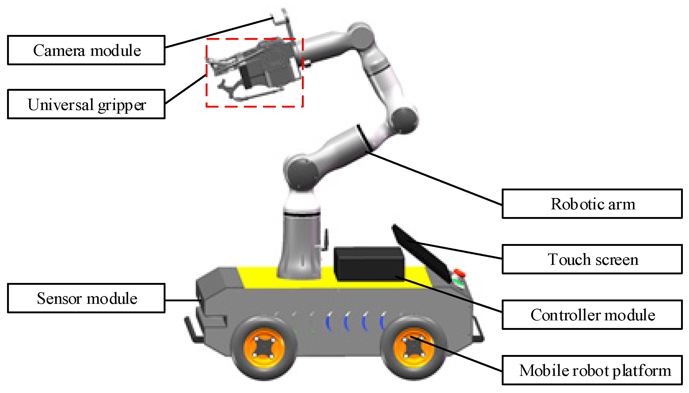
Figure 1. Structural layout of mobile robot.
Energies 15 09151 g001
Figure 2. Structural diagram of the underactuated gripper. (a) Component Diagram of the underactuated gripper. (b) Geometric parameters of the underactuated gripper.
Energies 15 09151 g002
Figure 3. The control system of the proposed universal gripper.
Energies 15 09151 g003
Figure 4. Overview of the gripper grasping objects: (a) Gripper structure. (b) Box Grab grabbing state. (c) Complex object grabbing state. (d) Grasp small objects by fingertips. (e) The envelope grips large objects. (f) cuboid objects transverse grasping state. (g) Two finger grasp status. (h) Transverse Horizontal grasping status. (i) 45 degree grasping status. (j) Vertical grasping status.
Energies 15 09151 g004
Figure 5. Mechanism diagram of the finger. (a) Grasping process. (b) Releasing process.
Energies 15 09151 g005
Figure 6. Establishment of the coordinate systems for the simplified finger.
Energies 15 09151 g006
Figure 7. Schematic diagram of geometric model of gripper envelope grab. (a) Physical picture. (b) Structure diagram.
Energies 15 09151 g007
Figure 8. Geometric model of grasping of the distal phalanx of the fingers. (a) Physical picture. (b) Structure diagram.
Energies 15 09151 g008
Figure 9. Simulation process of the gripper grabbing a sphere. (a) Grasping the ball. (b) Pinching the ball.
Energies 15 09151 g009
Figure 10. Changes in parameters in the process of grasping a sphere. (a) Grasping the ball: phalanxes rotation angle. (b) Grasping the ball: contact force. (c) Pinching the ball: phalanxes rotation angle; (d) Pinching the ball: contact force.
Energies 15 09151 g010aEnergies 15 09151 g010b
Figure 11. Simulation of gripper stress at different grasping methods. (a) Three-finger symmetrical grasp; (b) Three-finger parallel grasp.
Energies 15 09151 g011
Figure 12. Finite element analysis results of gripper. (a) Three-finger symmetrical grasp; (b) Three-finger parallel grasp.
Energies 15 09151 g012
Figure 13. Gripping objects of different shapes that are common in daily life.
Energies 15 09151 g013
Figure 14. Gripping objects of different orientations.
Energies 15 09151 g014
Figure 15. Robot grasping experiments. (a) Three fingers grasping object. (b) Two fingers grasping object.
Energies 15 09151 g015
Table 1. The various gripper structural schemes.
Structural Design CategoryAdvantagesDisadvantages
Mechanical hinge [30]High transmission efficiency, high joint stiffness and stable output force.1. Structure: redundancy, jumbled, bulky, inflexible, weak impact resistance;
2. High requirements for internal space configuration
Tendon, rope drive [31,32]Lightweight, flexible and applicable1. Joint stiffness is affected by the deformation of tendon and rope.
2. The friction interference between tendon and finger structure is large.
3. The transmission efficiency is low.
4. The service life is low.
Soft grippers [33,34,35]High structural flexibility, interaction safety, low cost, anti-interference.1. Low structural stiffness.
2. Difficult modeling.
3. Low control accuracy.
Rigid-flexible hybrid [36,37,38]Complaisance and reliable.Difficulty in fusion design.
Special configurations [39,40,41]Multi-functional, low cost.Poor universality.
Bionic joint [42,43]Highly humanoid, compliant, impact resistant and controllable.1. The cost is high.
2. The system is complex.
3. The drive requirements are high.
Table 2. Main equipment parameters.
Parameter NameParameter Value
Camera
(Intel realSense D435i)
Size90 mm × 25 mm × 25 mm
Precision<2%
Measurement distance range0.11–10 m
Depth resolution ratio1280 × 720
Robotic arm (RM65-B)Effective load5 kg
Re-orientation accuracy±0.05 mm
power voltageDC24 V
communication methodsWIFI; USB; RS485
Mobile robotOverall dimensions600 mm × 340 mm × 160 mm
Load15 kg
Driving motorsGB37-520
VoltageDC24 V
Motors
(Koala BEAR Beta)
Weight250 g
Speed constant27.3 RPM/V
Torque constant0.35 Nm/A
Gear ratio9
Table 3. Geometric parameters of the underactuated gripper.
ParametersSymbolValues (mm)
Total length of fingerL80
Distal phalanx lengthL127
Middle phalanx lengthL226
Proximal phalanx lengthL327
Linkage IVL4115
Finger distanceLs50
Total length of holderLh147
Overall sizeL × W × H115 × 97 × 227
Table 4. D–H parameters of the finger.
Phalanx iθiαiLidiRange of θi (°)
1θ10L1090–135
2θ20L200–90
3θ30L300–85
Publisher’s Note: MDPI stays neutral with regard to jurisdictional claims in published maps and institutional affiliations.