Article

Experimental Study of Pulsating Heat Pipes Filled with Nanofluids under the Irradiation of Solar Simulator

1
School of Aeronautic Science and Engineering, Beihang University, Beijing 100191, China
2
AVIC Shenyang Aircraft Design and Research Institute, Shenyang 110035, China
*
Authors to whom correspondence should be addressed.
Energies 2022, 15(23), 9153; https://doi.org/10.3390/en15239153
Submission received: 10 October 2022 / Revised: 21 November 2022 / Accepted: 24 November 2022 / Published: 2 December 2022

Abstract

:
Developing renewable energy technologies, especially solar technology, is of vital importance to cope with increasing energy consumption. The existing solar thermal systems have the disadvantages of capturing solar energy inefficiently and needing additional pumping power to circulate the working fluid. A concept of a direct absorption pump-free solar thermal system that combines the advantages of nanoparticles and pulsating heat pipes (PHP) is proposed in this work. The effects of a variety of parameters including nanoparticle types, nanoparticle concentration, and nanofluid filling rate on the performance of PHP were studied. It was found that PHP has the best filling rate (80–90%) making the best heat transfer performance and minimizing the thermal resistance. The concentration of nanoparticles affects the input power of the pulsating heat pipe and thus the operation of the PHP. The nanofluid with relatively low concentration cannot absorb enough solar energy to drive the PHP to operate normally. Experimental research shows that the new solar thermal system can absorb solar energy efficiently and transfer the heat into the targeted area spontaneously, which may be an approach for future solar thermal utilization.

1. Introduction

The development of renewable and sustainable energy, especially solar energy, has become crucial to meet the accelerating world’s energy consumption [1]. There are three categories of solar energy conversion and utilization methods in common use: solar thermal/photothermal (ST/PT), photovoltaic (PV), and photochemistry (PC). Solar thermal systems (STSs) occupy a large share [2]. In 2020, the total installed capacity of solar energy in the world was about 1451 GW, and the solar thermal utilization was about 522 GW, which accounts for 36% of the total installed capacity [3]. However, a traditional STS has two main disadvantages. One is that the process efficiency limitations of an STS in converting solar radiation to the internal energy of the working fluid has limitations, including the efficiency limitation of the solar absorber to capture solar radiation and the efficiency limitation of the heat energy transfer to the working fluid [4,5]. A traditional STS absorbs solar energy by adding a coating on the collector surface, which leads to the highest temperature at the surface of the collector and the lowest temperature at the center of the working fluid [6,7], resulting in high heat loss and large thermal resistance. The other disadvantage of the traditional STS is that extra pump power is required to drive the fluid circulation for the heat transfer, which further increases the energy consumption of the system. Therefore, it is necessary to develop novel solar thermal systems that can address these disadvantages in order to improve the photothermal utilization efficiency.
A pulsating heat pipe (PHP), first proposed in the 1990s [8], is an ideal choice to achieve pump-free heat transfer. A PHP has the advantages of a simple structure, low cost, high flexibility, and great heat transfer performance [9,10,11]. A PHP is composed of long capillary tubes bent into multiple bends, and the fluid circulation is driven by the bubble expansion of the evaporator section and the contraction of the condenser section without additional pumping power [12,13]. Some researchers have attempted to use PHPs to transfer solar energy and have verified their feasibility [14,15,16]. However, these researchers used PHPs to directly replace the water pipes or collector tubes in conventional solar collectors, which makes the solar energy not a direct heat source for the OHP, but first absorbs radiation through the surface of the collector thus driving the OHP operation to transfer heat. In addition, different from PHPs, Boris V. Balakin et al. [17] used magnetic nanofluids to achieve pump-free heat transfer. However, the system required a magnetic coil with additional power consumption to generate an external magnetic field to drive the system cycle.
In order to reduce the thermal resistance in converting solar energy into heat energy of the working fluid, researchers have proposed the concept of direct absorption heat collection (DASC) based on nanoparticles [18,19,20,21], i.e., volumetric absorption by adding nanoparticles into the working fluid. Most working fluids (such as water, ethanol, etc.) have a weak absorption capacity for solar radiation [22]. The addition of a lower-volume fraction of nanoparticles to the working fluid can significantly improve the photo-thermal conversion efficiency of the fluid due to the properties of small size and large specific surface effect of nanoparticles [19,20,23,24,25,26]. In addition, the solar energy conversion efficiency can be further significantly improved by designing the solar absorption spectrum in the nanoscale [27,28,29]. Certain metal nanoparticles, such as Ag and Au, have received widespread attention due to their surface plasmon resonance effects (SPR).
In addition, nanofluids will quickly generate steam under solar radiation [30,31,32,33], which is also beneficial to the operation of PHPs. It has been demonstrated that rapid steam production is realized under focused sunlight while the bulk fluid is still in the subcooled state [34,35,36], which means that only a small part of solar energy is used to increase the bulk fluid temperature. Using solar energy to generate steam has gradually attracted the attention of scholars worldwide [37,38,39,40]. Compared with the traditional steam-generating device, the use of nanofluids and solar energy not only reduces the use of fossil energy but also eliminates the need for high temperatures that can generate significant heat loss. Researchers have proposed the hypothesis of nanobubbles to explain the generation of vapor. The rapid heating of nanoparticles generates nanobubbles around the nanoparticles and the nanobubbles rise to the upper surface of the liquid, thereby releasing the generated vapor [41,42,43]. It has been proved that under the heating of an intensive laser, bubbles are indeed generated around the heated nanoparticles [44]. However, it has recently been discovered that nanobubbles will not be generated under a relatively low heat flux [45]. Jin et al. [6] found that the generation of steam is mainly caused by the highly uneven distribution of temperature and radiant energy through the combination of experiments and mathematical models. This uneven distribution also leads to uneven pressure distribution in PHPs, which promotes PHP operation, theoretically.
This paper proposes a novel solar thermal utilization system that combines the concepts of DASC and PHP based on nanofluids. This system realizes volume absorption by filling a transparent capillary glass tube with nanofluid, thereby greatly improving the process efficiency of converting solar radiation into the internal energy of the working fluid. Meanwhile, it also has the advantages of the PHP in that the heat transfer is achieved by the expansion and contraction of the gas plugs and the liquid slugs in the PHP without additional pump power. In our previous study [46], the feasibility of this system has been verified under outdoor natural concentrated sunlight. Limited by the experimental equipment, the experimental conditions were relatively rough and difficult to adjust, so there is a lack of comparative studies of the system performance. In this paper, we have conducted extensive research on this novel system under the laboratory conditions using an solar simulator, investigating the influence of nanofluid type, nanofluid concentration, and PHP filling rate on the system performance, and analyzing the PHP temperature distribution, the movement of the gas plugs and the liquid slugs in the PHP, and the thermal resistance. The novel system has the potential to be a new type of solar collector with the advantages of volume absorption, no pump, and compactness.

2. Experimental System

Ag nanoparticles (AgNPs) and multi-walled carbon nanotubes (MWCNT), which have a strong ability to absorb sunlight, are selected to prepare different nanofluids to fill PHPs. The two-step method is used to prepare stable nanofluids. First, the powder is dispersed in deionized water (DI water) and placed in an ultrasonic bath (ThermoFisher Scientific, FB11207) for 30 min. Next, the dispersion is treated with a 50% power ultrasonic cell disruption (UCD) system (ThermoFisher Scientific, FB705) for 2 h. After the nanofluids preparation, they are characterized using scanning electron microscope (SEM) (JEM-1200EX), transmission electron microscope (TEM) (Tecnai G2 F20 S-TWIN), and UV spectrophotometer (Shimadzu UV-1800). The distribution, particle size, and spectral absorption characteristics of the nanoparticles in nanofluid can be obtained, respectively, as shown in Figure 1 and Figure 2. The change in absorbance is compared after the nanofluids are left to stand for 2 months, and the difference is less than 1%, indicating its good stability.
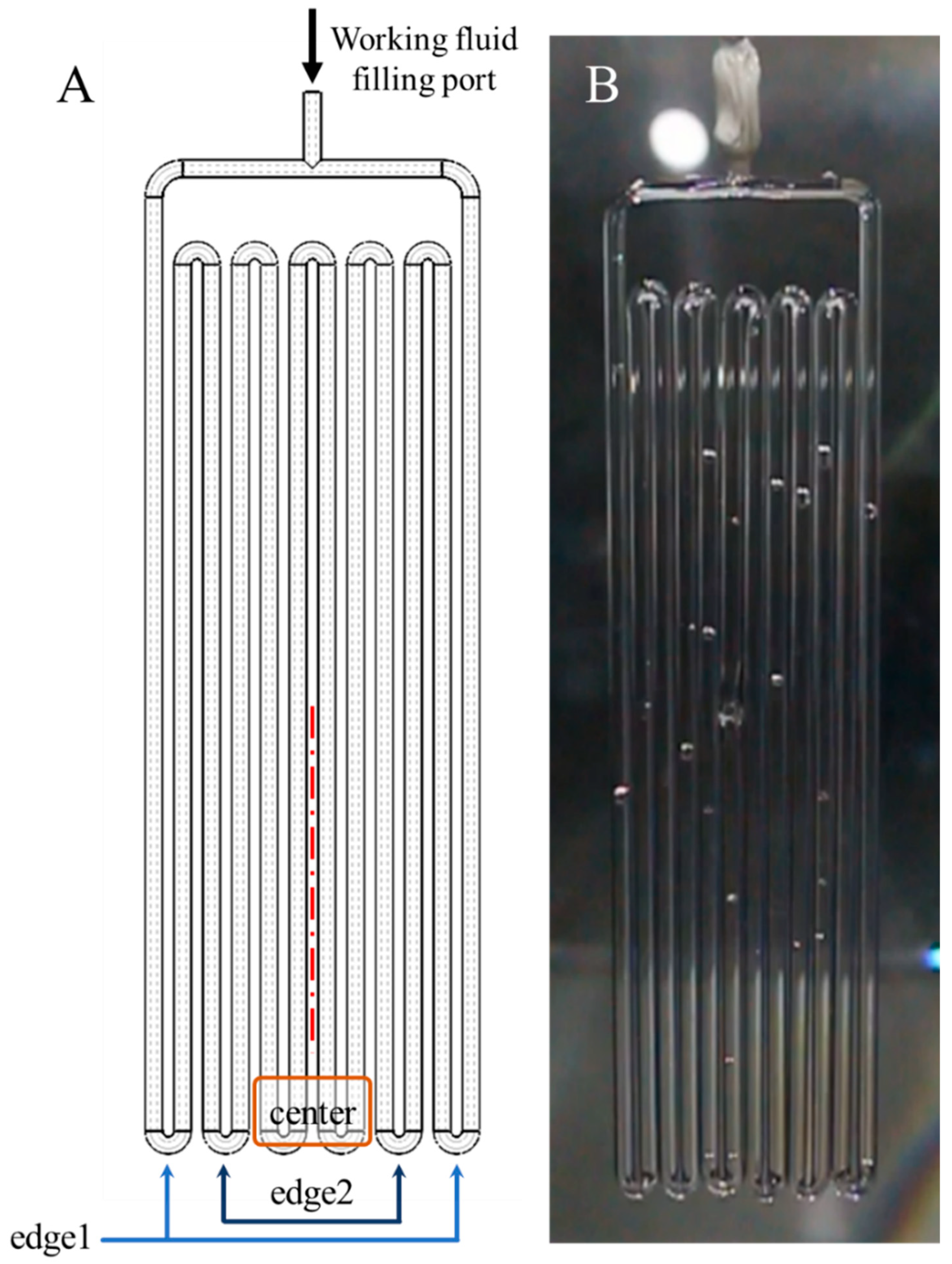
The PHP is made of solar-grade quartz with high light transmission and excellent thermal insulation performance. The PHP capillary pipes have the inner diameter of 2 mm and a pipe length of 200 mm. As shown in Figure 3, the PHP has 12 pipes, which are numbered 1 to 12 from left to right. The average temperature of the evaporation section of pipes 1, 2, 11, and 12 is recorded as edge1, the average temperature of pipes 3, 4, 9, and 10 is recorded as edge2, and the average temperature of pipes 5 to 8 is recorded as the center.
As shown in Figure 4, a solar simulator (ABET sun3000) is used to simulate sunlight, and a Fresnel lens (China Shenzhen Meiying Technology Co., Ltd.) is used to condense the sunlight, with a focal length of 100 cm and a condensing factor of 25. An infrared camera (Fluke Tix 640, 30 mm lens) with an accuracy of ±0.1 °C is used to capture the temperature distribution and variations of PHP. In order to record the bubble generation and increase process, a high-performance video camera (Canon EOS 70 D, 18–135 mm lens) is used for recording. The methodology flowchart of the experiment is shown in Figure 5. Each experiment is conducted twice and the deviation of temperature distribution is maintained at 10%.

3. Results and Discussion

3.1. Effect of Nanofluid Concentration

A series of controlled experiments are carried out to investigate the effect of nanofluid concentration. The temperature variations of the PHP for different nanofluid concentrations with the filling ratio of 80% are shown in Figure 6. Before the start of the experiment, the temperature of each part of the PHP are the same as the ambient temperature, nearly 25 °C. Comparing Figure 6A,B, it can be found that the temperature variations of the PHP filled with DI water and 0.001 wt% AgNPs are very similar. During the experiment, the temperature of the working fluid steadily increased without oscillation, meanwhile, the temperature of the condensation section remained almost unchanged. The main reason is that the start-up of the PHP does not occur for the experimental period. The working fluid in the evaporation section cannot reach the condensing section, so the heat is mainly transferred by conduction. Therefore, the temperature of condensing section cannot have a noticeable increase due to the high thermal resistance. In addition, since the spot area is small after the sunlight is focused and cannot cover all the evaporation sections, the center temperature in the evaporation section increases much faster than the edge1 and edge2 temperatures.
As shown in Figure 6C, for the PHP filled with 0.01 wt% AgNPs, the temperature of the evaporation section rises sharply when sunlight is applied. The center temperature of the evaporation section reaches above 60 °C within 100 s, which is higher than the final temperature in the experiment of the DI water case. After that, the center temperature no longer increases drastically, but begins to fluctuate around 60 °C, which indicates that PHP is already in operating condition at this time and begins to oscillate to transfer heat from the evaporation section to the condensation section. As shown in Figure 6D, for the PHP filled with 0.02 wt% AgNPs, the temperature of the evaporation section rises faster. The center temperature of the evaporation section reaches 60 °C in only about 70 s, and begins to fluctuate. The fluctuation is greater in magnitude and faster in frequency than the fluctuation at the concentration of 0.01 wt%. Meanwhile, the temperature of the condensation section increases significantly, which is also easily drawn from the comparison of infrared images.
It can be seen that under the irradiation of low-concentrated solar intensity, the operation of the PHP is greatly affected by the nanofluid concentration. The PHP filling with low-concentration nanofluid cannot start-up within the experimental period. The main reason for this phenomenon is that the addition of nanofluid increases the solar absorption capacity while increasing the flow resistance of the working fluid. The low-concentration nanofluid has no significant beneficial effect on the start-up and operation of the PHP. The concentration of nanofluids needs to be high enough so that enough solar energy can be captured to drive the PHP and improve its performance. The ability of the working fluid to absorb solar energy improves with the increase in nanofluid concentration, which means that the input power of PHP increases, thus directly affecting the operation of the PHP. As a result, the start-up time of the PHP is shortened and the thermal resistance is reduced, which will be analyzed in detail in Section 3.2.

3.2. Heat Transfer Performance Analysis

Different from the conventional PHP, the energy transfer process of the solar nanofluid PHP is that the solar energy is converted into thermal energy by volumetric absorption in the evaporation section and then transferred to the condensation section by oscillating motion. Therefore, the photothermal conversion efficiency of the nanofluid needs to be analyzed. According to previous research [6,28], the nanoparticles in the nanofluids should scatter sunlight independently, and the absorption and scattering coefficients can be calculated according to the Mie scattering theory. The solar energy absorbed by the PHP can be calculated by the following equation:
Q a b s = η f v η l η t η f I S
where η f v is the photothermal conversion efficiency of each concentration of nanofluid, η l is the efficiency of the Fresnel lens ( η l 95 % , experimentally determined), and η t is the ratio of the area of PHP in the condensing zone to the total area of the light spot, and η f is the filling rate of PHP. According to our previous works, η f v can be calculated:
η f v = 0 R p 0.2   μ m 3   μ m E λ 1 e 2 κ λ f v r d λ d r R p 0.2   μ m 3   μ m E λ d λ
where R p , E , and f v are the pipe radius of the PHP, the spectral emissive power, and the nanoparticle concentration, respectively. κ is the photothermal conversion coefficient of nanofluid, which can be considered as the sum of the conversion coefficient of the base liquid (DI water) and the conversion coefficient of the nanoparticles.
Substituting the absorbance measured by the spectrophotometer into the above formula, the photothermal conversion efficiencies of each concentration of nanofluids and DI water are calculated as shown in the table below.
The inner diameter of PHP should be small enough (such as 2 mm in the experiment) for the working fluid to formulate gas plugs and liquid plugs. According to research [47], the photothermal conversion efficiency is very sensitive to the optical path when the optical path is less than 20 mm. For an optical depth of 2 mm, the photothermal conversion efficiency is very low, which severely limits the performance of the PHP. It can be seen from Table 1 that adding a small amount of nanoparticles in water can significantly improve the photothermal conversion efficiency of the working fluid. When the concentration of Ag nanoparticles is 0.001 wt% and 0.002 wt%, the photothermal conversion efficiency is close to that of DI water, which is consistent with the result that the PHP does not oscillate and the temperature variations are similar in the three cases of the experiments.
The system energy efficiency and thermal resistance can evaluate the heat transfer capability of the system. The system efficiency is the percentage of the system output energy to the input energy. For this work, the condensing section is naturally convection cooled and the system has a large heat leakage, which makes it difficult to calculate the system output energy, so the analysis of system energy efficiency is not shown here in detail. In order to quantify the performance of heat transfer in different cases, the thermal resistance of the PHP is calculated:
R = T ¯ e T ¯ c Q a b s  
where T ¯ e , T ¯ c are the average temperatures of the evaporation section and the condensation section during the operation of the PHP. According to the error analysis method [48], the uncertainty of thermal resistance can be calculated:
U R R = 2 U T T ¯ e T ¯ c 2 + U I I 2
In the formula, U R is the uncertainty of thermal resistance, and U T and U I are the uncertainty of temperature and sunlight intensity, respectively. The calculation shows that U R R is less than 5% in each group of experiments; therefore, the error bars are not shown in the relevant figures to ensure data clarity.
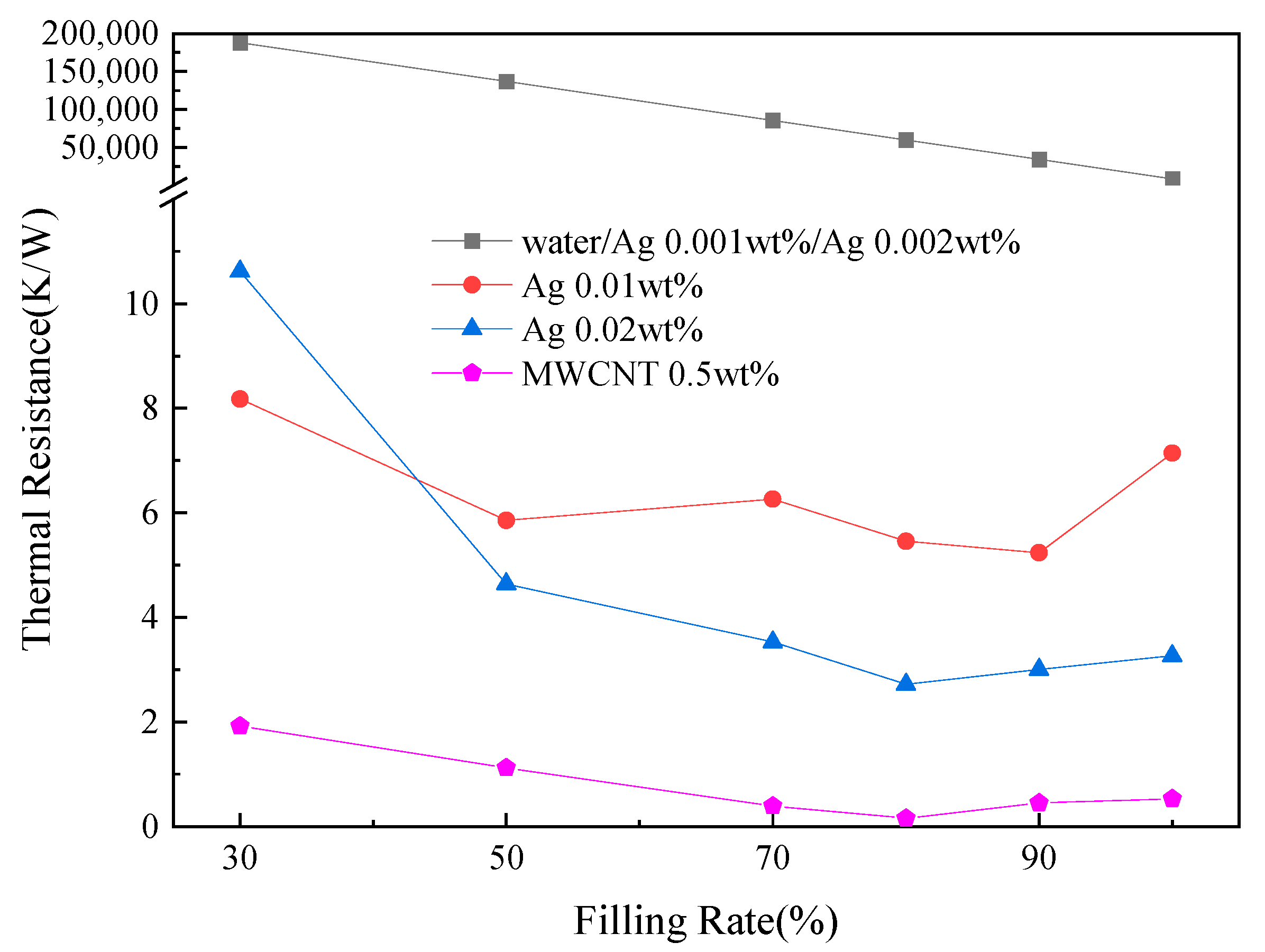
Figure 7 shows the thermal resistance of each concentration of nanofluid at different filling rates. For DI water and relatively low-concentration nanofluids, the PHP does not oscillate during the experiment as mentioned in Section 3.1. Therefore, the thermal resistance is calculated theoretically from the thermal conductivity of the working fluid and the results are relatively large. It can be seen from Figure 7 that the addition of nanofluid can significantly reduce the thermal resistance of the PHP. However, when the concentration of nanofluid is relatively low, the heat absorption of the evaporation section of the PHP is not greatly improved and the PHP cannot operate. By comparing Figure 7 and Table 1, it can be conclude that the thermal resistance of the PHP decreases with the improvement of photothermal conversion efficiency of the nanofluid.
Previous studies have found that for the traditional PHP, the oscillation phenomenon is only observed when the filling rate ranges from 20% to 80%. When the filling rate exceeds the maximum filling rate, the PHP cannot start-up even with a high heat flow in the evaporation section. The maximum filling rate of the conventional PHP is calculated [49]:
ϕ m a x = u l u v + u l = 1 1 + k R T ρ 1 K 1 2
For a given PHP, the maximum filling rate depends on the physical properties of the working fluid and the operating temperature. It can be estimated from Equation (5) that the maximum filling rate of the PHP with water as the working fluid is about 76% at an operating temperature of 335 K.
From the thermal resistance analysis, we found that for the nanofluid PHP of our experiment, there exists an optimal filling rate to minimize its thermal resistance (10.617 K/W at the filling rate of 30% for the PHP filled with 0.05 wt% AgNPs, 2.719 K/W at the filling rate of 80%). The filling rate of the PHP determines the distribution of the liquid plugs and gas plugs in the PHP. If the filling rate is too low, the evaporation section may burn out and then hinder operation. In the experiment, the best filling rate is between 80% and 90%. The optimal filling rate is higher than theoretical calculation and previous research [10]. The main reason is that the nanofluid is not only the working fluid of the PHP, but it also plays the role of absorbing solar energy in this experiment. Therefore, the filling rate needs to be higher so that more nanofluid can be in the evaporation section to capture enough solar energy.

3.3. Temperature Fluctuation and Quasi-Sine Oscillation Analysis

The temperature fluctuation of each section of the PHP reflects the heat transfer and operation process more visually. It can be seen from Figure 6 that when the PHP is starting up, the temperature of the condensation section fluctuates around a certain working temperature. Compared with the PHP filling with DI-water, we can reveal that the addition of nanofluid increases the working temperature and reduces the working temperature difference (between condensation section and evaporation section). As shown in Figure 6C,D, it can be found that the working temperature in the case of 0.02 wt% is about 68 °C, which is higher than the case of 0.01 wt% (62 °C). Furthermore, for the case of 0.02 wt%, the period of temperature fluctuation becomes smaller and the amplitude becomes larger. These findings suggest that the increase in the concentration improves the absorption efficiency of the evaporation section, the heating power increases, and the oscillation of the gas plug and liquid plug of the working fluid in the tube is enhanced.
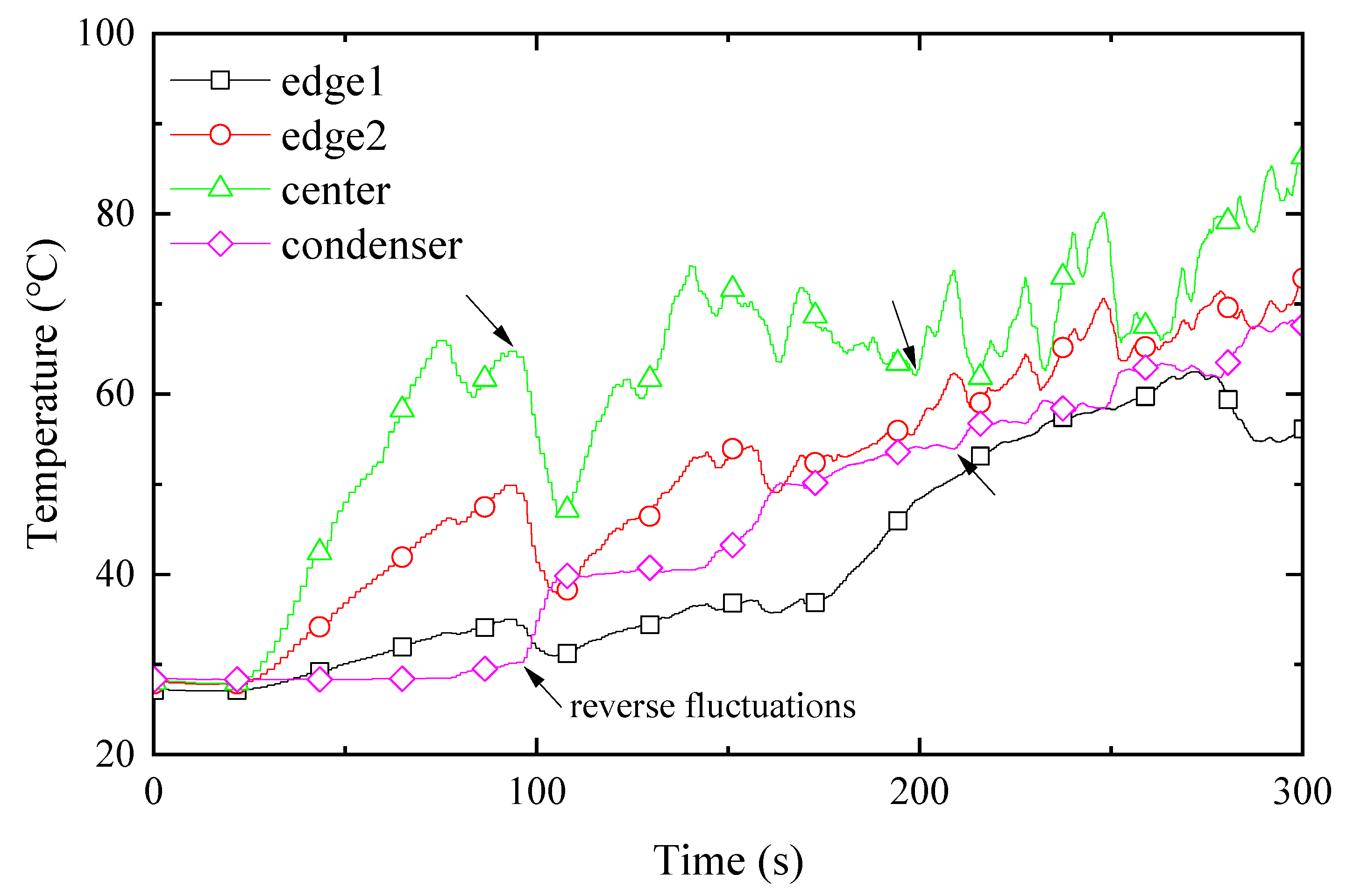
In order to clearly observe the temperature fluctuation and quasi-sine oscillation, the results of the PHP filling with 0.5 wt% MWCNTs were selected for analysis. As shown in Figure 8, the temperature change curve of the four-part PHP shows obvious fluctuations. With the PHP operating, the temperature of edge1 is even lower than the condensation section after running for about 100 s, as a result of the light spot not completely covering the edge of the PHP. Taken together, the temperature fluctuation can be separated into small-amplitude irregular fluctuations and quasi-sine fluctuations. The reason for the small-amplitude irregular fluctuation is mainly the non-uniform and discontinuous small-amplitude oscillation in the tube. For the quasi-sine fluctuations, the accompanying reverse fluctuations between the evaporation section and the condensation section can be found (as marked by arrows in Figure 8). The reverse fluctuations could be attributed to the cycle in which the evaporation section absorbs heat to make the gas plug oscillate to the condensation section to release heat, which is the ideal operating condition of the PHP. The appearance of the reverse fluctuations indicates that the PHP has a good operating performance, and the working fluid has quasi-sine motion in most moments.
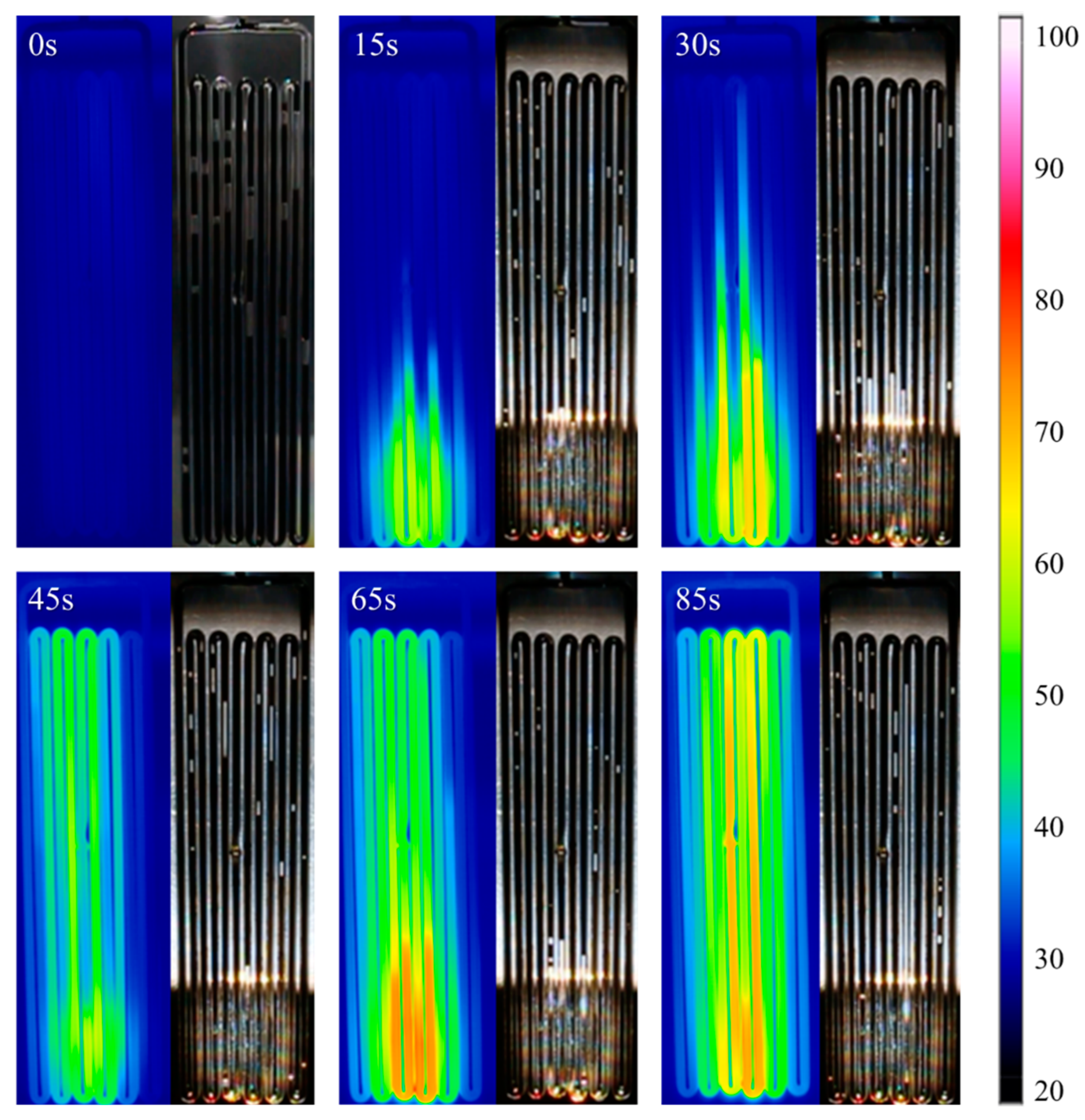
Combined with the infrared images, as shown in Figure 9, in the beginning, the temperature of the PHP is equivalent to the ambient temperature, around 25 °C. After applying sunlight, the evaporation section of the PHP begins to heat up. Because the spot area cannot cover the entire evaporation section, the temperature increases unevenly. After 30 s, the temperature in the evaporation section is already high, and the high-temperature zone begins to extend to the condensation section. Then, 45 s later, the temperature of the evaporation section decreases, and the condensation section begins to show a large temperature rise, which indicates that part of the working fluid in the evaporation section has flowed to the condensation section. The temperature of the evaporation section continues to rise at 65 s. Then, the working fluid flows to the condensation section again after 20 s, causing the temperature of the evaporation section to decrease. The operating temperature of the PHP acted in a quasi-sine oscillating mode. This phenomenon can also be observed in temperature variations of the PHP, as shown in Figure 9. Although the temperature of the PHP continues to rise due to the natural cooling method, it can still be seen that its temperature curve, especially the curve of center temperature, is similar to a quasi-sine oscillation.

3.4. Gas Plugs Movement and Pumping Thrust Analysis

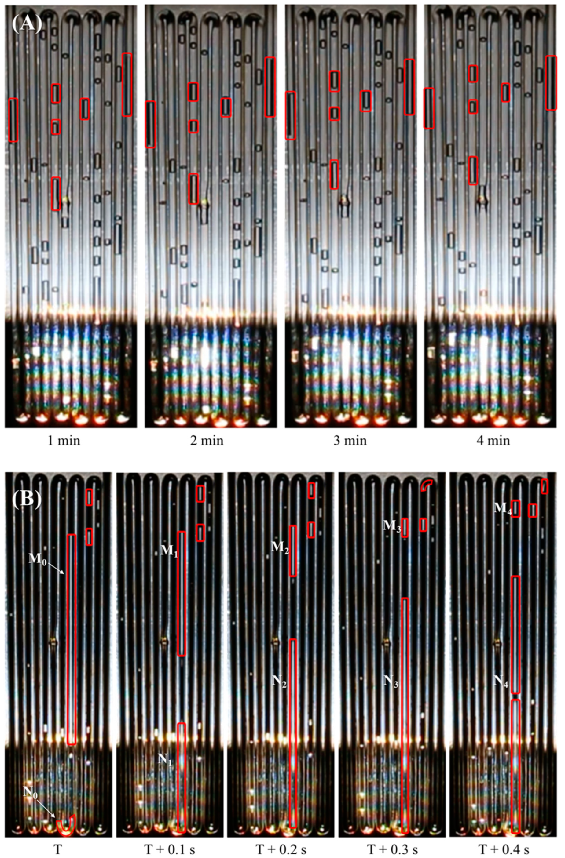
The growth and movement of gas plugs have an important influence on the heat transfer performance of the PHP. The flow regime variation during the experiment for the DI water and MWCNTs nanofluid are shown in Figure 10. Through observation, the rules of bubble movement are as follows:
(1).
The size of the gas plugs for the DI water is generally small (there are no gas plugs longer than 3 cm), which leads to a large number of gas plugs in the PHP, as shown in the red rectangles in Figure 10A. In addition, the distribution of gas plugs presents a random state and is not affected by their location in PHP. For PHP filled with nanofluids, the number of gas plugs is smaller. As shown in the red rectangles in Figure 10B, there are both large-size gas plugs and small-size gas plugs and some extra-long bubbles can reach more than 10 cm. In the distribution of gas plugs, the large-size gas plugs often appear in the evaporation section and the adiabatic section, and the small-size gas plugs are usually located in the condensation section.
(2).
The gas plugs of the DI water hardly move. As shown in Figure 10A, even if the time scale is extended to minutes, the gas plug distribution in the PHP is almost unchanged. From 1 min to 4 min, there is indeed a displacement of the gas plugs. However, the displacement is extremely small, and no sudden acceleration of the gas plugs can be seen in the video. The average velocity of the gas plugs is approximately 6.66 × 10 5   m / s , which is almost negligible. The lack of working fluid flow in the PHP greatly limits its heat transfer performance. However, for the nanofluid, the gas plugs move violently. The gas plugs moving speed can reach 0.55 m/s.
(3).
For the nanofluid, as shown in Figure 10B, a small gas plug in the evaporation section grows rapidly from about 1 cm (N0) to more than 10 cm (N3) in only 0.3 s after being heated. At the same time, a gas plug that was originally located above the small gas plug was quickly pushed to the condensation section. As the gas plug reaches the condensation section and begins to release heat, the length of the gas plug gradually decreases, from about 10 cm to less than 1 cm. This process explains well why gas plugs in PHPs have a such distribution rule.
The acceleration of the bubble can be obtained from the video to calculate the thrust of the working fluid in PHP. Obviously, the acceleration of PHP filled with nanofluid is much higher. The thrust can be calculated by the following formula:
F = θ m m a x a
where a is the acceleration, and θ , m m a x are the filling rate and the internal volume of PHP, respectively. Assuming that there is no fractional force from the inner face, the maximum thrust for PHP filled with 0.5 wt% MWCNTs fluid can reach about 0.0069 N. By comparing with our previous research [47], the thrust in the research can be about 8 times higher than that in this experiment. The sunlight is concentrated 500 times through the Fresnel lens in the previous research [47], while in this experiment, the solar is only concentrated 25 times. The difference in solar concentration causes a certain gap in the heat absorption of the PHP evaporation section. Based on the fact that the PHPs used in the two experiments are almost the same, the conclusion can be drawn that the difference in heat absorption in the evaporation section leads to a large difference in thrust. The pressure difference between the evaporating section and the condensing section is the main factor in the formation of the thrust in PHPs, and it can be obtained from the saturation pressure–temperature curve based on the temperatures of two sections. The greater the heat absorption of the evaporation section, the greater the temperature difference between the evaporation section and the condensation section, resulting in greater pressure difference and the formation of greater thrust.

4. Conclusions

This work experimentally validated a novel solar thermal system combining DASC and OHP concepts based on nanofluids to achieve efficient solar energy utilization without pumps, providing a new solution for solar thermal utilization with efficient heat collection and heat transfer capabilities. Experiments on this novel system were conducted under solar simulator conditions to verify the feasibility of the system, and its heat transfer characteristics and oscillation characteristics were investigated. The effects of nanofluid type, nanofluid concentration, and the PHP filling rate on the system were examined. Through the investigations above, the conclusions below can be reached:
  • When the nanofluid concentration is relatively low, the PHP under low-concentrated solar intensity cannot operate and the temperature variations are similar to that of the PHP filled with DI water. For a higher concentration, the performance of the PHP improves with the increase in nanofluid concentration.
  • There is an optimal filling rate for the PHP to achieve the best heat-transfer performance, and the optimal filling rate is between 80 and 90%. The minimum thermal resistance reaches 0.157 K/W for PHP filled with 0.5 wt% MWCNTs nanofluid at the filling rate of 80%.
  • The quasi-sine oscillating behavior is observed in the experiment, under the appropriate concentration and filling rate of nanofluids.
  • For PHPs that will operate, the large-size gas plugs often appear in the evaporation section and the adiabatic section, and the small-size gas plugs are usually located in the condensation section due to the contraction and expansion of gas plugs in different sections. Further investigation should be focused on selecting proper nanoparticle type and concentration and optimizing the PHP structure to increase the energy efficiency. In addition, the system energy efficiency can be further investigated by focusing precisely on the output power of the condensation section.

Author Contributions

Conceptualization, H.J.; methodology, S.L. and H.J.; formal analysis, K.M.; investigation, K.M.; resources, S.L. and X.J.; data curation, Y.Y., K.M. and X.J.; writing—original draft, Y.Y.; writing—review & editing, S.L.; supervision, H.J.; project administration, S.L. All authors have read and agreed to the published version of the manuscript.

Funding

This work was supported by the National Natural Science Foundation of China (No. 51906010 and No. 12172029) and the Fundamental Research Funds for the Central Universities.

Institutional Review Board Statement

Not applicable.

Informed Consent Statement

Not applicable.

Data Availability Statement

Not applicable.

Conflicts of Interest

The authors declare no conflict of interest.

References

  1. Tian, Y.; Zhao, C.Y. A review of solar collectors and thermal energy storage in solar thermal applications. Appl. Energy 2013, 104, 538–553. [Google Scholar] [CrossRef] [Green Version]
  2. Lewis, N.S. Research opportunities to advance solar energy utilization. Science 2016, 351, aad1920. [Google Scholar] [CrossRef] [PubMed] [Green Version]
  3. Gibb, D.; Ledanois, N.; Ranalder, L.; Yaqoob, H. Renewables 2022 Global Status Report; REN21: Paris, France, 2022. [Google Scholar]
  4. Lenert, A.; Wang, E.N. Optimization of nanofluid volumetric receivers for solar thermal energy conversion. Sol. Energy 2012, 86, 253–265. [Google Scholar] [CrossRef] [Green Version]
  5. Bertocchi, R.; Karni, J.; Kribus, A. Experimental evaluation of a non-isothermal high temperature solar particle receiver. Energy 2004, 29, 687–700. [Google Scholar] [CrossRef]
  6. Jin, H.C.; Lin, G.P.; Bai, L.Z.; Zeiny, A.; Wen, D.S. Steam generation in a nanoparticle-based solar receiver. Nano Energy 2016, 28, 397–406. [Google Scholar] [CrossRef] [Green Version]
  7. Slaman, M.; Griessen, R. Solar collector overheating protection. Sol. Energy 2009, 83, 982–987. [Google Scholar] [CrossRef]
  8. Akachi, H. Structure of a Heat Pipe. United States Patent U.S. 4,921,041, 1 May 1990. [Google Scholar]
  9. Ma, H.B.; Wilson, C.; Borgmeyer, B.; Park, K.; Yu, Q.; Choi, S.U.S.; Tirumala, M. Effect of nanofluid on the heat transport capability in an oscillating heat pipe. Appl. Phys. Lett. 2006, 88, 143116. [Google Scholar] [CrossRef]
  10. Zhang, Y.; Faghri, A. Advances and unsolved issues in pulsating heat pipes. Heat Transf. Eng. 2008, 29, 20–44. [Google Scholar] [CrossRef] [Green Version]
  11. Qu, W.; Ma, H.B. Theoretical analysis of startup of a pulsating heat pipe. Int. J. Heat Mass Transf. 2007, 50, 2309–2316. [Google Scholar] [CrossRef]
  12. Ma, H. Oscillating Heat Pipes; Springer: New York, NY, USA, 2015. [Google Scholar]
  13. Chen, Y.; He, Y.; Zhu, X. Flower-type pulsating heat pipe for a solar collector. Int. J. Energy Res. 2020, 44, 7734–7745. [Google Scholar] [CrossRef]
  14. Rittidech, S.; Wannapakne, S. Experimental study of the performance of a solar collector by closed-end oscillating heat pipe (CEOHP). Appl. Therm. Eng. 2007, 27, 1978–1985. [Google Scholar] [CrossRef]
  15. Kargarsharifabad, H.; Mamouri, S.J.; Shafii, M.B.; Rahni, M.T. Experimental investigation of the effect of using closed-loop pulsating heat pipe on the performance of a flat plate solar collector. J. Renew. Sustain. Energy 2013, 5, 013106. [Google Scholar] [CrossRef]
  16. Arab, M.; Soltanieh, M.; Shafii, M.B. Experimental investigation of extra-long pulsating heat pipe application in solar water heaters. Exp. Therm. Fluid Sci. 2012, 42, 6–15. [Google Scholar] [CrossRef]
  17. Balakin, B.V.; Stava, M.; Kosinska, A. Photothermal convection of a magnetic nanofluid in a direct absorption solar collector. Sol. Energy 2022, 239, 33–39. [Google Scholar] [CrossRef]
  18. Minardi, J.E.; Chuang, H.N. Performance of a “black” liquid flat-plate solar collector. Sol. Energy 1975, 17, 179–183. [Google Scholar] [CrossRef]
  19. Bandarra, E.P.; Mendoza, O.S.H.; Beicker, C.L.L.; Menezes, A.; Wen, D.S. Experimental investigation of a silver nanoparticle-based direct absorption solar thermal system. Energy Convers. Manag. 2014, 84, 261–267. [Google Scholar] [CrossRef]
  20. Zhang, H.; Chen, H.J.; Du, X.Z.; Wen, D.S. Photothermal conversion characteristics of gold nanoparticle dispersions. Sol. Energy 2014, 100, 141–147. [Google Scholar] [CrossRef]
  21. Khanafer, K.; Vafai, K. A review on the applications of nanofluids in solar energy field. Renew. Energy 2018, 123, 398–406. [Google Scholar] [CrossRef]
  22. Otanicar, T.P.; Phelan, P.E.; Golden, J.S. Optical properties of liquids for direct absorption solar thermal energy systems. Sol. Energy 2009, 83, 969–977. [Google Scholar] [CrossRef]
  23. Rahman, M.M.; Al-Mazroui, W.A.; Al-Hatmi, F.S.; Al-Lawatia, M.A.; Eltayeb, I.A. The role of a convective surface in models of the radiative heat transfer in nanofluids. Nucl. Eng. Des. 2014, 275, 382–392. [Google Scholar] [CrossRef]
  24. Hussain, I.; Graham, S.; Wang, Z.X.; Tan, B.; Sherrington, D.C.; Rannard, S.P.; Cooper, A.I.; Brust, M. Size-controlled synthesis of near-monodisperse gold nanoparticles in the 1–4 nm range using polymeric stabilizers. J. Am. Chem. Soc. 2005, 127, 16398–16399. [Google Scholar] [CrossRef] [PubMed]
  25. Hwang, S.H.; Yun, J.; Jang, J. Multi-Shell Porous TiO2 Hollow Nanoparticles for Enhanced Light Harvesting in Dye-sensitized Solar Cells. Adv. Funct. Mater. 2014, 24, 7619–7626. [Google Scholar] [CrossRef]
  26. Halas, N.J.; Neumann, O.; Urban, A.; Hogan, N.; Fang, Z.Y.; Pimpinelli, A.; Lal, S.; Nordlander, P. Solar Vapor Generation Enabled by Nanoparticles. Abstracts of Papers of the American Chemical Society. 2013. Available online: https://www.webofscience.com/wos/alldb/full-record/WOS:000329618406075 (accessed on 9 October 2022).
  27. Khullar, V.; Tyagi, H.; Hordy, N.; Otanicar, T.P.; Hewakuruppu, Y.; Modi, P.; Taylor, R.A. Harvesting solar thermal energy through nanofluid-based volumetric absorption systems. Int. J. Heat Mass Transf. 2014, 77, 377–384. [Google Scholar] [CrossRef]
  28. Jin, H.C.; Lin, G.P.; Bai, L.Z.; Amjad, M.; Bandarra, E.P.; Wen, D.S. Photothermal conversion efficiency of nanofluids: An experimental and numerical study. Sol. Energy 2016, 139, 278–289. [Google Scholar] [CrossRef] [Green Version]
  29. Jin, H.C.; Lin, G.P.; Zeiny, A.; Bai, L.Z.; Wen, D.S. Nanoparticle-based solar vapor generation: An experimental and numerical study. Energy 2019, 178, 447–459. [Google Scholar] [CrossRef]
  30. Neumann, O.; Urban, A.S.; Day, J.; Lal, S.; Nordlander, P.; Halas, N.J. Solar Vapor Generation Enabled by Nanoparticles. ACS Nano 2013, 7, 42–49. [Google Scholar] [CrossRef]
  31. Ni, G.; Li, G.; Boriskina, S.V.; Li, H.X.; Yang, W.L.; Zhang, T.J.; Chen, G. Steam generation under one sun enabled by a floating structure with thermal concentration. Nat. Energy 2016, 1, 16126. [Google Scholar] [CrossRef]
  32. Li, X.Q.; Xu, W.C.; Tang, M.Y.; Zhou, L.; Zhu, B.; Zhu, S.N.; Zhu, J. Graphene oxide-based efficient and scalable solar desalination under one sun with a confined 2D water path. Proc. Natl. Acad. Sci. USA 2016, 113, 13953–13958. [Google Scholar] [CrossRef] [Green Version]
  33. Zhou, L.; Tan, Y.L.; Ji, D.X.; Zhu, B.; Zhang, P.; Xu, J.; Gan, Q.Q.; Yu, Z.F.; Zhu, J. Self-assembly of highly efficient, broadband plasmonic absorbers for solar steam generation. Sci. Adv. 2016, 2, e1501227. [Google Scholar] [CrossRef] [Green Version]
  34. Lukianova-Hleb, E.; Hu, Y.; Latterini, L.; Tarpani, L.; Lee, S.; Drezek, R.A.; Hafner, J.H.; Lapotko, D.O. Plasmonic Nanobubbles as Transient Vapor Nanobubbles Generated around Plasmonic Nanoparticles. ACS Nano 2010, 4, 2109–2123. [Google Scholar] [CrossRef]
  35. Fang, Z.; Zhen, Y.-R.; Neumann, O.; Polman, A.; de Abajo, F.J.G.; Nordlander, P.; Halas, N.J. Evolution of Light-Induced Vapor Generation at a Liquid-Immersed Metallic Nanoparticle. Nano Lett. 2013, 13, 1736–1742. [Google Scholar] [CrossRef] [PubMed] [Green Version]
  36. Tullius, T.K.; Bayazitoglu, Y. Temperature of a metallic nanoparticle embedded in a phase change media exposed to radiation. Int. J. Heat Mass Transf. 2016, 93, 980–990. [Google Scholar] [CrossRef]
  37. Yu, S.; Zhang, Y.; Duan, H.; Liu, Y.; Quan, X.; Tao, P.; Shang, W.; Wu, J.; Song, C.; Deng, T. The impact of surface chemistry on the performance of localized solar-driven evaporation system. Sci. Rep. 2015, 5, srep13600. [Google Scholar] [CrossRef] [PubMed] [Green Version]
  38. Bae, K.; Kang, G.; Cho, S.K.; Park, W.; Kim, K.; Padilla, W.J. Flexible thin-film black gold membranes with ultrabroadband plasmonic nanofocusing for efficient solar vapour generation. Nat. Commun. 2015, 6, 10103. [Google Scholar] [CrossRef] [Green Version]
  39. Shannon, M.A. Water Desalination Fresh for Less. Nat. Nanotechnol. 2010, 5, 248–250. [Google Scholar] [CrossRef]
  40. Elimelech, M.; Phillip, W.A. The Future of Seawater Desalination: Energy, Technology, and the Environment. Science 2011, 333, 712–717. [Google Scholar] [CrossRef]
  41. Chen, X.; Munjiza, A.; Zhang, K.; Wen, D. Molecular Dynamics Simulation of Heat Transfer from a Gold Nanoparticle to a Water Pool. J. Phys. Chem. C 2014, 118, 1285–1293. [Google Scholar] [CrossRef]
  42. Baffou, G.; Quidant, R.; de Abajo, F.J.G. Nanoscale Control of Optical Heating in Complex Plasmonic Systems. ACS Nano 2010, 4, 709–716. [Google Scholar] [CrossRef]
  43. Donner, J.S.; Baffou, G.; McCloskey, D.; Quidant, R. Plasmon-Assisted Optofluidics. ACS Nano 2011, 5, 5457–5462. [Google Scholar] [CrossRef]
  44. Hou, L.; Yorulmaz, M.; Verhart, N.R.; Orrit, M. Explosive formation and dynamics of vapor nanobubbles around a continuously heated gold nanosphere. New J. Phys. 2015, 17, 013050. [Google Scholar] [CrossRef]
  45. Ni, G.; Miljkovic, N.; Ghasemi, H.; Huang, X.; Boriskina, S.V.; Lin, C.-T.; Wang, J.; Xu, Y.; Rahman, M.M.; Zhang, T.; et al. Volumetric solar heating of nanofluids for direct vapor generation. Nano Energy 2015, 17, 290–301. [Google Scholar] [CrossRef] [Green Version]
  46. Jin, H.; Lin, G.; Zeiny, A.; Bai, L.; Cai, J.; Wen, D. Experimental study of transparent oscillating heat pipes filled with solar absorptive nanofluids. Int. J. Heat Mass Transf. 2019, 139, 789–801. [Google Scholar]
  47. Jin, H.; Lin, G.; Guo, Y.; Bai, L.; Wen, D. Nanoparticles enabled pump-free direct absorption solar collectors. Renew. Energy 2020, 145, 2337–2344. [Google Scholar] [CrossRef]
  48. Moffat, R.J. Describing the uncertainties in experimental results. Exp. Therm. Fluid Sci. 1988, 1, 3–17. [Google Scholar] [CrossRef] [Green Version]
  49. Yin, D.; Rajab, H.; Ma, H. Theoretical analysis of maximum filling ratio in an oscillating heat pipe. Int. J. Heat Mass Transf. 2014, 74, 353–357. [Google Scholar] [CrossRef]
Figure 1. (A) TEM image for AgNPs; (B) SEM image for MWCNTs.
Energies 15 09153 g001
Figure 2. (A) Spectral-dependent absorbance of silver and MWCNT nanofluids under different volume fractions; (B) Absorption peak of silver nanofluids at different concentrations.
Energies 15 09153 g002
Figure 3. (A) Apparatus of PHP and temperature statistics group setting; (B) photograph of PHP.
Energies 15 09153 g003
Figure 4. (A) Experimental schematic of solar nanofluid pulsating heat pipe experiment; (B) photograph of solar nanofluid pulsating heat pipe experiment: 1. filling system; 2. solar simulator; 3. Fresnel lens; 4. PHP; 5. infrared camera and video camera.
Energies 15 09153 g004
Figure 5. The methodology flowchart.
Energies 15 09153 g005
Figure 6. Temperature variations of the PHP with the filling ratio of 80%: (AD) filling with DI water, 0.001 wt% AgNPs, 0.01 wt% AgNPs, and 0.02 wt% AgNPs nanofluid, respectively. The inset shows the photographs and infrared images 120 s after solar radiation.
Energies 15 09153 g006
Figure 7. Variation of the thermal resistance with the filling ratio for PHP filled with different nanofluids.
Energies 15 09153 g007
Figure 8. Temperature variations of the PHP filled with 0.5 wt% MWCNTs nanofluid with a filling ratio of 80%.
Energies 15 09153 g008
Figure 9. Infrared images and photos from a high-speed camera of the PHP filled with 0.5 wt% MWCNTs nanofluid with a filling ratio of 80%.
Energies 15 09153 g009
Figure 10. Bubble growth and dynamic movement of the PHP filled with (A) DI water and (B) 0.5 wt% MWCNTs with a filling ratio of 80% (the time 0 s represents that the solar simulator is turned on). The red rectangles indicate the location and size of the selected gas plugs at different times.
Energies 15 09153 g010
Table 1. Photothermal conversion efficiency of different nanofluids.
DI WaterAg 0.001 wt%Ag 0.002 wt%Ag 0.01 wt%Ag 0.02 wt%MWCNT 0.5 wt%
η f v 11.86%12.2%12.53%16.42%19.55%70.74%
Publisher’s Note: MDPI stays neutral with regard to jurisdictional claims in published maps and institutional affiliations.