Review

A Review on Power Electronic Topologies and Control for Wave Energy Converters

School of Engineering, Lancaster University, Lancaster LA1 4YW, UK
*
Author to whom correspondence should be addressed.
Energies 2022, 15(23), 9174; https://doi.org/10.3390/en15239174
Submission received: 17 October 2022 / Revised: 26 November 2022 / Accepted: 30 November 2022 / Published: 3 December 2022

Abstract

:
Ocean energy systems (OESs) convert the kinetic, potential, and thermal energy from oceans and seas to electricity. These systems are broadly classified into tidal, wave, thermal, and current marine systems. If fully utilized, the OESs can supply the planet with the required electricity demand as they are capable of generating approximately 2 TW of energy. The wave energy converter (WEC) systems capture the kinetic and potential energy in the waves using suitable mechanical energy capturers such as turbines and paddles. The energy density in the ocean waves is in the range of tens of kilowatts per square meter, which makes them a very attractive energy source due to the high predictability and low variability when compared with other renewable sources. Because the final objective of any renewable energy source (RES), including the WECs, is to produce electricity, the energy capturer of the WEC systems is coupled with an electrical generator, which is controlled then by power electronic converters to generate the electrical power and inject the output current into the utility AC grid. The power electronic converters used in other RESs such as photovoltaics and wind systems have been progressing significantly in the last decade, which improved the energy harvesting process, which can benefit the WECs. In this context, this paper reviews the main power converter architectures used in the present WEC systems to aid in the development of these systems and provide a useful background for researchers in this area.

14. Introduction

Increasing the dependency on renewable energy sources (RESs) to produce the required electrical energy has become a spearhead concept in the development of any country [1,2,3,4,5,6,7]. Firstly, RESs will achieve the sustainability of the energy sources and will increase the political independency. Secondly, the RESs can help the European and other governments who have promised to reach the international goal of net-zero carbon by 2030. These RESs can take several forms including wind, solar, geothermal, ocean, and others. The progress in the technology associated with these energy systems will improve the economic, environmental, and social outcomes set and targeted by the governments and policymakers [8,9,10]. There is a noticeable global increase in the penetration of the RESs in electric markets in the previous 10 years [11,12,13,14]. The average penetration of renewable energy in electricity networks reached around 30% [12]. For example, Greece has been successful in powering the electricity networks, consuming 3106 MWh entirely from renewable energy for five hours on the 7th of October 2022. On average, RESs form 46% of Greece’s power mix in 2022, which consists of solar photovoltaic (PV), wind turbines (WTs), and Ocean Energy Systems (OESs) [15].
Because of their availability in many countries, OESs are one of the most promising RESs, which are gaining increased attention by the governments and policymakers [16]. It is estimated that the total ocean energy which could be harvested is more than 100,000 TWh/year [17]. This is more than the energy demand by all countries in the world [18]. Accordingly, understanding, developing, and improving the OCEs become important to achieve the net-zero carbon goal.
OESs aim to extract the energy from the oceans and seas and they have been presented and studied in the previous few decades. Ocean energy can be in the forms of potential or kinetic energy in the waves, tidal or currents, heat, and salinity gradients [19]. Therefore, they are broadly classified as wave energy, currents, thermal, and tidal energy systems. For the ocean wave energy, usually mechanical turbines extract the potential and kinetic energy of the moving water inside the waves when they are moving up and down [20]. Ocean thermal energy systems target the transferred energy between warm water at the surface of the ocean and the cold water in the deep layers [21]. The tidal energy is produced essentially from the gravitational interaction between the Moon and the Earth and, therefore, the kinetic energy in the moving water is captured by turbines [22]. If there is suitable infrastructure of turbines, electric generators, and power systems, it is estimated that the tidal systems supply the world with more than 450 GW of power [23].
The wave energy conversion (WEC) systems convert the kinetic energy in the waves using braking systems and dampers into electricity [24]. WECs can supply the world with up to 60,000 TW.h/year [25]. If they are fully utilized, the WEC systems can generate power of approximately 2 TW, which will help in reducing the carbon emissions globally [1]. There are several publications which study and classify the WEC systems according to the principle of operation, their location on the shore, or the direction of the incoming waves [26,27,28,29,30,31,32,33,34,35,36]. If the WEC systems are to be classified according to the principle of operation, the main types will be oscillating water column (OWC), wave activated body (WAB), and over-topping (OT). The current energy conversion (CEC) systems are mainly composed of axial-flow turbines such as horizontal or vertical axes, cross-flow turbines, and reciprocating devices systems [37]. The tidal energy systems have arrays of floodgates in order to direct the water streams on turbines coupled with electrical generators through channels. Most of these turbines are horizontal-axis axial-flow. In thermal gradient (TG) systems, the thermal gradient of ocean water is used to evaporate a liquid and direct it on the blades of a turbine coupled with an electrical generator [36]. The TG systems are classified into open cycle, closed cycle, and hybrid systems [37]. Finally, the salinity gradient (SG) systems are divided into reverse electro-dialysis, which accumulates pressure to drive a turbine, and pressure retarded osmosis systems, which accumulate an electric voltage across two plates to form a battery. This classification is summarized in Figure 1.
As the WEC systems have large energy density when compared with other energy systems, they can be a main key player to increase the sustainability of the energy sector [38]. An example is the Wave Dragon project in Denmark, which started in 2003 as the world’s first offshore WEC system. Presently, it produces 51 GWh/year of electrical energy in total, where it has 1.5 MW and 4 MW devices in Denmark, a 7 MW device in Wales, and a 12 MW device in Portugal. Many other projects are still in the demonstration and commercialization stages. In other European countries, such as the United Kingdom, WEC systems produce around 25% of the total electricity demand [39].
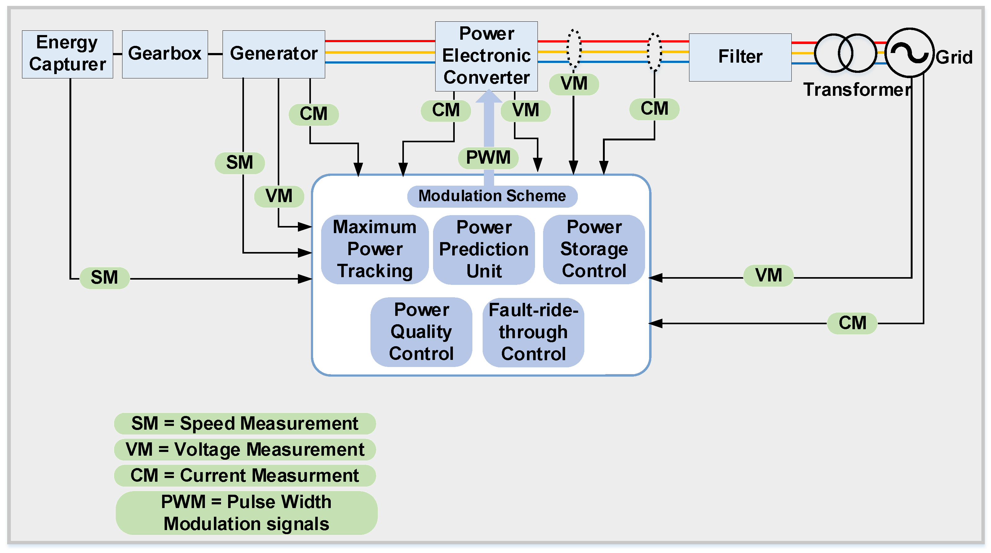
Following the energy capturing and extraction systems explained earlier, it is important to investigate the electrical energy conversion systems. This system is composed of the electrical generator coupled to the rotational or linear shafts with gearboxes, the power converter systems, the power transfer systems such as cables and filters, and finally the electrical transformers for grid connection. A general schematic for a WEC system controller is shown in Figure 2. The electrical generators are designed to operate at high rotational speed when compared with the oscillating speed of the waves and, accordingly, the rotational speed of the energy extractor, which is a turbine in this case [5]. Therefore, it is necessary to install a gearbox system in order to match the two speeds and torques. Most of the electrical generators produce time-variant voltages and currents, and their time periods and frequencies depend mainly on the rotational speed of the generator shaft [40]. Accordingly, it is necessary to rectify the voltage and current in order to make them suitable for grid connection. Most of the AC utility grids in the world operate with frequency of 50 Hz and some other few countries have 60 Hz networks such as the USA. Modulation techniques are required to shape the electricity from a shape to another using power electronic converters. This is usually done by switching the semiconductor devices inside the converters on and off according to designed control laws. Most of the renewable energy systems, including WECs, generate the maximum energy at a certain operating point in their power–speed curves [41]. Therefore, the maximum power point tracking (MPPT) controller is designed to operate the system at the optimum point to increase the harvested power and increase the efficiency of the WEC system. Variable speed controllers will be installed in order to control the speed of the generator and achieve the MPPT operation. If the WEC system is coupled with energy storage elements such as batteries or super-capacitors, the power storage control will determine and control the energy flow to either the utility grid or the energy storage according to the power supply and demand, which is predicted by the power prediction unit [5].
The power quality control unit is responsible for improving the quality of the output power of the converter by reducing its total harmonic distortion (THD) to meet the electrical grid standards [42,43]. In distributed generation systems, it is important to consider two types of the harmonics in the output current and voltage. The first are the low-order harmonics, which are generated due to mismatches in the circuit parameters or due to an unbalance in the grid voltages. This type of harmonics can be eliminated by the aid of improving the control and modulation schemes [5,44]. The second type are the high order harmonics, which are produced due to the switching action of the IGBTs/MOSFETs inside the converter. This can be eliminated by either increasing the switching frequency of the converters or by increasing the values of the filtering elements [45,46]. The RESs can contribute to the fault currents when there is an electrical fault such as three-phase to ground or line-to-line faults and hence the protection devices such as switchgears and circuit breakers may not function properly to isolate the fault [47]. The fault rides through controller unit installed with this distributed generator, which is the WEC in this case, and is responsible for limiting the generated power to decrease the contribution to this fault and allow the protection devices to function properly and isolate the fault [47].
This paper focuses on reviewing the power electronic converter architectures used in the context of WEC systems. The paper categorizes the main power conversion topologies and presents discussions about each type in detail. Section 2 presents important considerations for choosing the power conversion system. Section 3 reviews and classifies the main WEC power electronic converters. Section 4 presents discussions about the future of possible power electronic systems in WEC systems. Section 5 presents the summary and final conclusions.

2. WEC Electrical Considerations

The wave’s energy is transferred at the wave group velocity, which is normally in the range of 5 to 10 m/s [20]. This variation in the energy’s frequency means that the captured power by the absorber will be also varying with time. Therefore, the electrical generator will be working in a pulsating pattern, which will be reflected in the generated voltages and currents, see Figure 3. Therefore, the associated power electronic converters are necessary to reshape this pulsating electrical power and make it constant with time in order to be suitable for the utility grid [16]. The power’s pulsating nature will be significant when the WEC system is connected to a weak grid and can affect its performance negatively. However, connecting WEC systems to weak grids is very common because usually the wave activity is very high in remote areas where the electricity grids are normally weak. This adds more burden on the power electronic converters’ design process in the WECs.
Because they are installed near to the sea water, the electrical generators in WEC systems will operate in harsh environmental conditions due to the humidity, corrosion, vibrations, and mechanical stresses because of the aforementioned power pulsating pattern [38]. Accordingly, it is recommended to use multipole generators with direct-drive controllers.
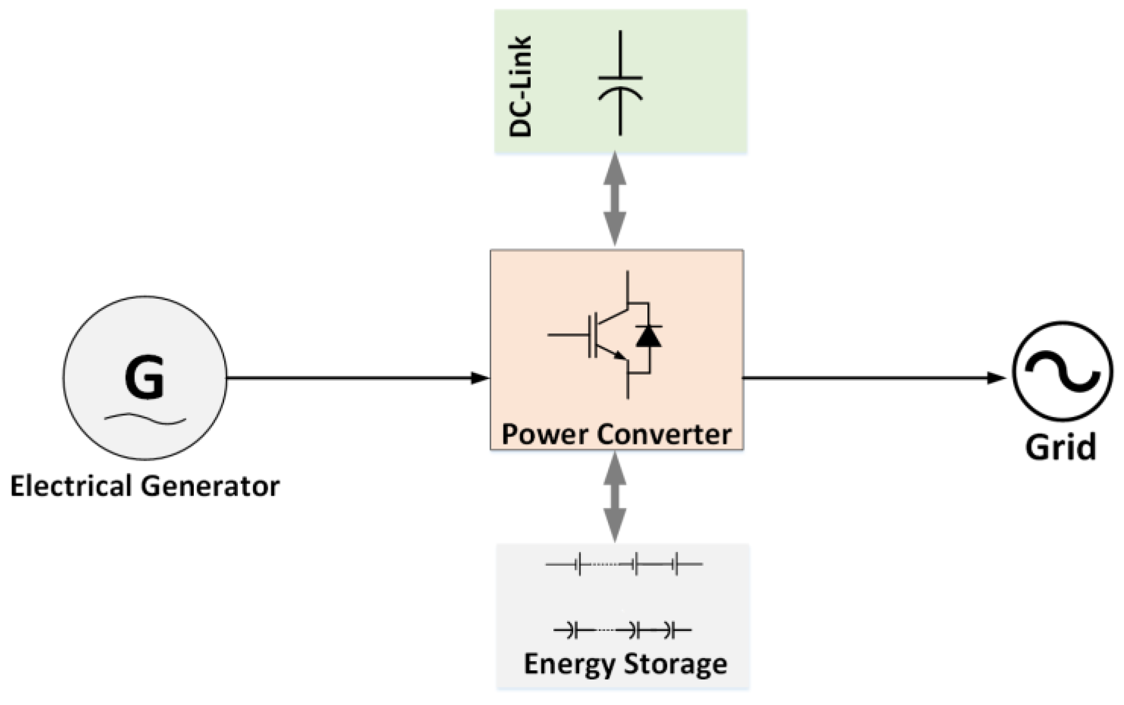
Because the wave activity is usually higher during the off-peak periods of the electricity network, it will be necessary to install energy storage systems (ESSs) to smooth the power delivery. ESSs such as flywheel mechanisms, batteries, and super-capacitors can also help in smoothing the generated power from the WEC systems, which can improve the performance when connected with weak grids. It has been reported in [48] that, to make the total output power constant with time, the installed energy storage capability should be at least ten times the wave period. The energy flow in a WEC system with ESS is shown in Figure 4.
The power harvested from a WEC system can be maximized if the phase of the device’s speed divided by the phase of the wave’s excitation force is adjusted to a specific value [49]. To control this operation, the electrical power converter is required to have bidirectional power flow between its input and output, which will be improved also by using ESSs. However, this operation is sometimes complicated and also results in large currents and voltages, which may damage the converter.

3. Electrical System of the WECs

The power electronic converters are responsible for two main functions in the WEC system. Firstly, they control the electrical power output from the generator, which is coupled with the WEC turbine. Secondly, they shape this power to be suitable for connection to the output side, which can be the utility grid or an independent load [3]. From the electrical point of view, the output power of the WECs is different when compared with other famous renewable energy sources. An example is the solar photovoltaic (PV) modules which generate continuous DC voltages and currents [50]. Therefore, the associated power electronic converter in the PV system is usually of DC/AC type to generate the AC grid’s voltages and currents at 50/60 Hz. For wind turbine systems (WTSs), the motion of the mechanical turbine is rotational in one direction even if its speed will be changing according to the linear wind speed, and hence the output voltages and currents are AC [51]. However, the output power of the WECs is usually oscillatory because the mechanical system moves up and down or forward and backward at relatively low speeds [38]. Thus, the performance of the associated power electronic converters will be different with other renewable energy systems even if the same type of power converter has been used. Figure 5 shows a brief schematic for the WEC process. There are different architectures for power electronic converters which are suitable for WEC applications such as the back-to-back AC/DC/DC, modular cascaded converters, and DC/DC converters.

3.1. AC/DC/AC Back-to-Back Converters

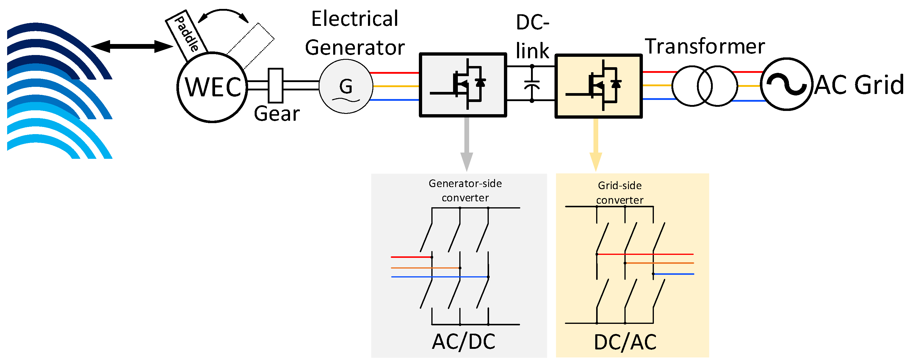
Inspired by the wind turbine systems, the AC/DC/AC power converter and its descendants are dominating the power conversion topologies in WEC systems [52,53,54,55,56,57]. In this configuration, the turbine is coupled with an electrical generator which its terminals are connected to the input of an AC/DC full-bridge rectifier. The output of this rectifier forms the DC-link of the system. The DC-link voltage is then modulated using a DC/AC inverter to generate the sinusoidal voltages to match the AC utility grid. The best example for this system is the rotating paddle type shown in Figure 6, which belongs to the family of the oscillating water WECs.
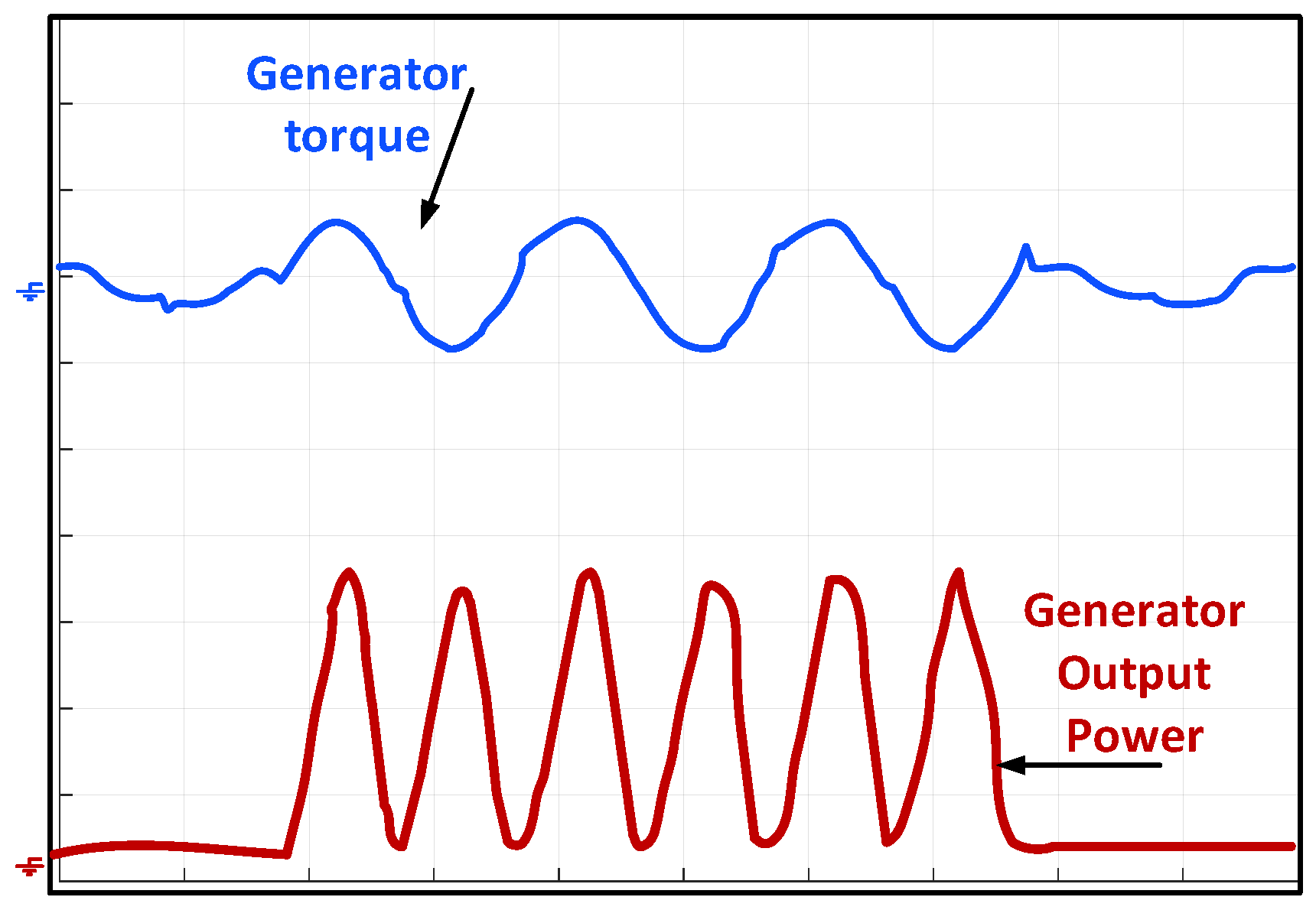
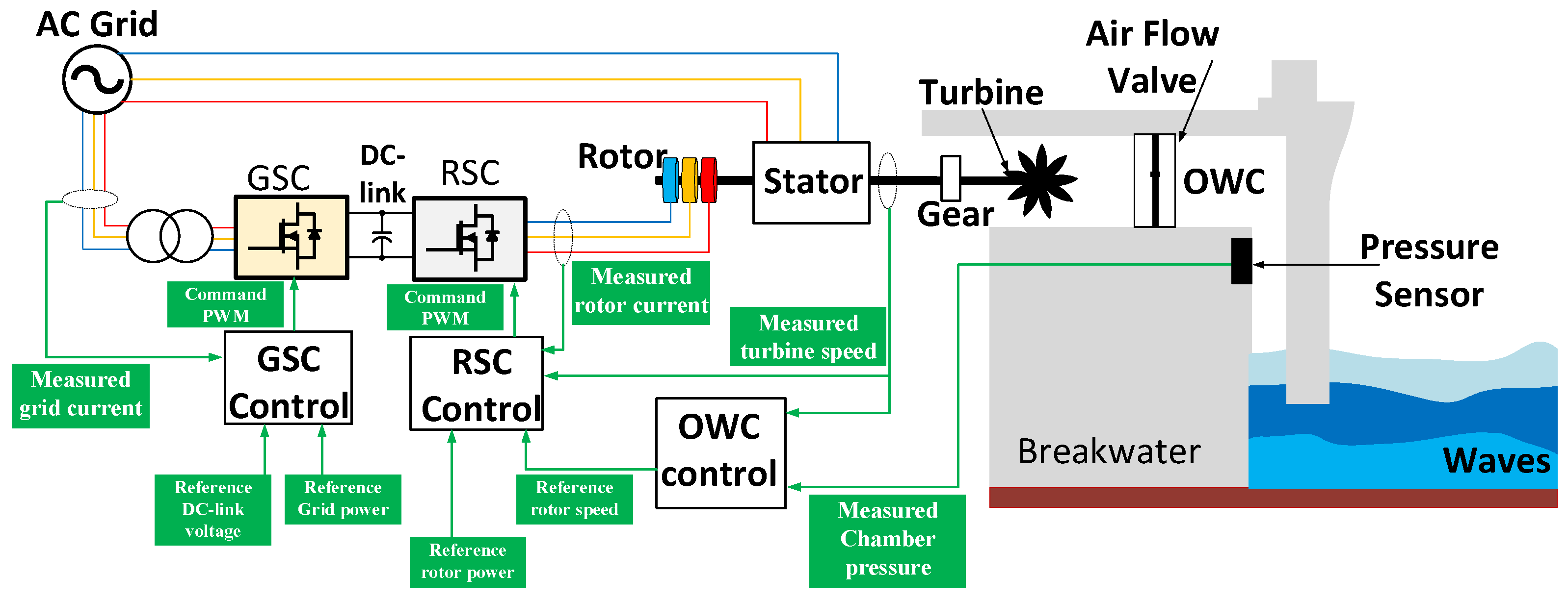
Usually, the permanent magnet synchronous generator (PMSG) is employed in this type of WECs due to the simplicity of connection, although it is possible to use other types such as a doubly-fed induction generator (DFIG) [52]. An interesting work has been carried out in [53], where the authors successfully developed a mathematical model for the paddle-type WEC. We have reproduced some interesting results for the model using MATLAB/SIMULINK and the results are almost the same as shown in Figure 7, where the electrical generator speed was plotted versus the output voltage of the generator. Because of the oscillatory nature of the WEC system, the generator speed is sinusoidal with a period of a few seconds. This leads the output voltage of the generator to be oscillatory as well, which should be considered by the modulation scheme if the grid-side converter is chosen as a controllable AC/DC converter to control the DC-link directly. This will complicate the modulation scheme of the rectifier and, therefore, it is easier to design the rectifier stage as a full-bridge diode rectifier. Because of the oscillatory nature of the paddle and its associated mechanical system, the mechanical torque of the generator shaft is also oscillatory, as shown in Figure 8. Unlike other RESs which have constant power at the generator, the output power from the WEC electrical generator is oscillatory, which complicates the control design. For this reason, many publications tried to explore the best control strategy for the generator and the grid side’s converters. In [54], the authors employed a DFIG instead of the PMSG and proposed a control scheme based on the classical proportional-integral (PI) control loops to control the rotor and stator sides, see Figure 9. The main contribution of this work is not in the control of the electrical side but in studying, designing, and controlling the WEC based on an oscillating water column to maximize the output power. To achieve that, a proportional-integral-derivative (PID) controller has been introduced and tuned to control the throttle valve which regulates airflow in the turbine duct. As shown in Figure 9, the developed OWC control block calculates the speed reference, which maximizes the output power of the system. The rotor-side control (RSC) tracks this speed by controlling the rotor of the DFIG which is coupled in the same shaft with the turbine. The RSC generates the command pulse width modulation (PWM) signals to control the AC/DC rectifier. The grid-side control (GSC) is responsible for controlling the DC-link voltage as well as the rotor’s output power. As the work in [54] was focusing on the control of the OWC throttle valve to regulate the airflow, it did not consider the conduction or switching losses of the rotor- or the grid-side converters. Therefore, the work has presented the turbine torque and the flow coefficient clearly, but the DC-link voltage and generator’s current behaviors have not been considered.
There have been several attempts to reduce the switch count of the AC/DC/AC converter of WEC systems. In [55], a four-switch converter has been used as the three-phase rectifier on the PMSG side, which is shown in Figure 10. The model of predictive current control has been presented to increase the accuracy of current references tracking. Although the presented control scheme has been successful in controlling the d-axis and q-axis currents, the work lacks the sufficient discussion about the instantaneous currents flowing in the IGBT devices in either the rectifier or the inverter. Consequently, there is a real need to monitor and study the waveforms of the currents flowing in the semiconductor devices and take them into consideration during the design stage. This is also necessary to evaluate the added value by reducing the number of semiconductor devices and if there is a considerable improvement in the efficiency or the cost.
An insightful comparison between the current source converter (CSC) and the voltage source converter (VSC) in the context of WEC systems is presented in [56,57]. The CSCs are boost converters, which chop and direct the currents instead of chopping voltages as in the case of the conventional VSCs. If the CSC is employed as an inverter, it will be able to boost the output voltage to be higher than the input one. This function is not available in the conventional VSCs. Therefore, the CSC is used extensively in the field of medium-voltage drives when high voltages need to be generated across the motor’s terminals. The CSC requires a large inductor in the DC-link instead of the large capacitor. Figure 11 shows the CSC topology used in the comparison of [56,57].
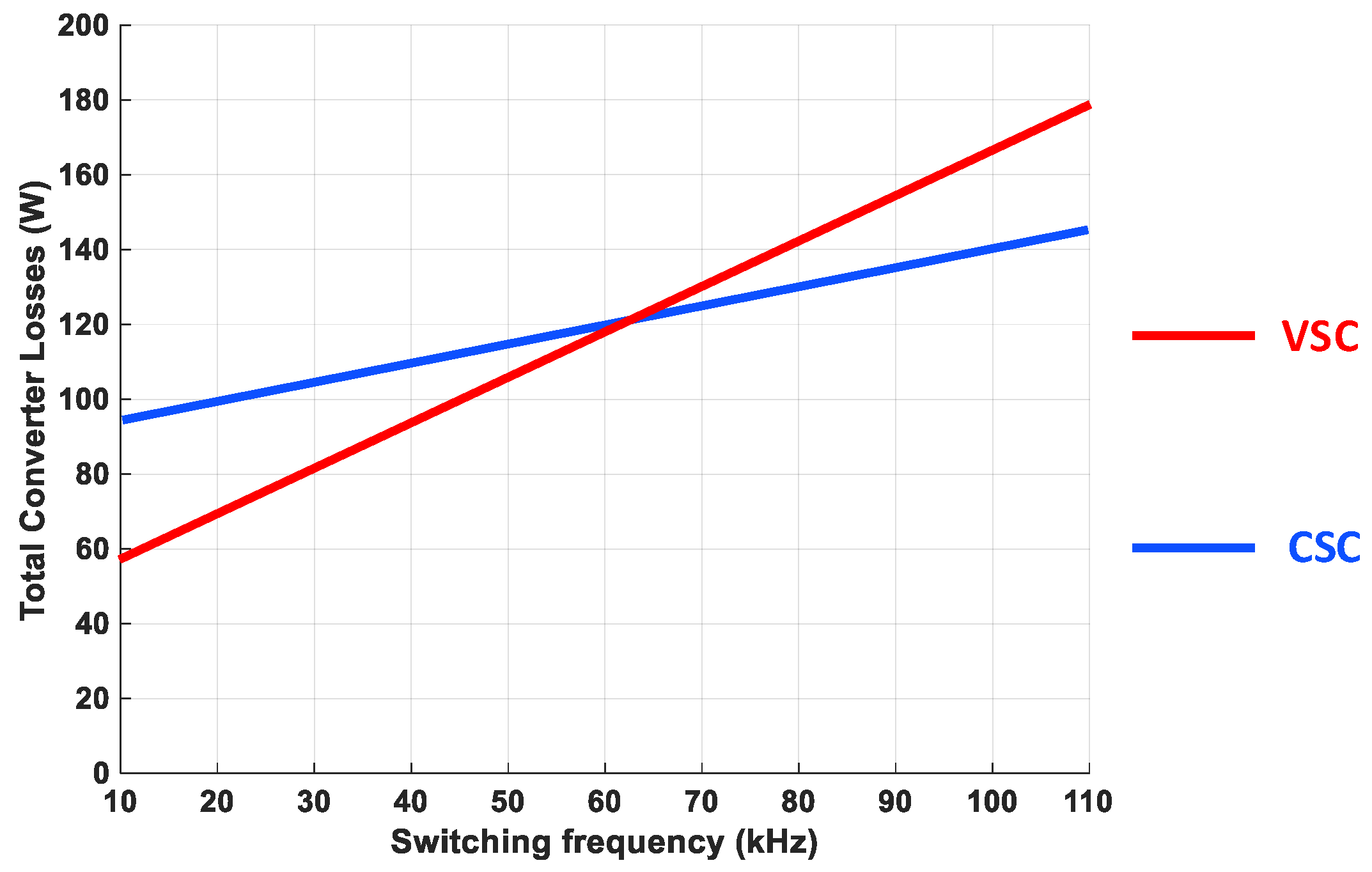
The comparison has considered the switching and conduction losses in the IGBTs and the diodes as well as the conduction losses in the passive elements. The work concluded that if the switching frequency of the active switches is kept lower than 30 kHz, then the conventional VSC topology has better efficiency and should be used. If the switching frequency is increased, the CSC becomes more efficient with lower power losses and smaller filtering passive elements, and consequently has a lower cost. The comparison’s outcomes are shown in Figure 12. Although the authors have shown the waveforms of the currents flowing in the semiconductor devices in detail, the power losses have been calculated by simulations and experimental results without presenting the mathematical equations required to assess the losses if the operational points or the parameters’ values are changed.
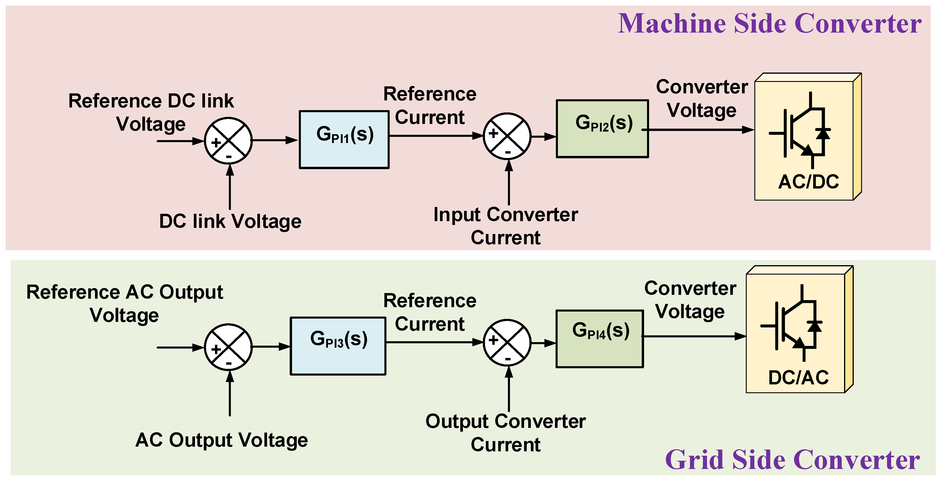
Beside improving the power electronic structure, several publications targeted improving the control schemes of the WEC AC/DC/AC back-to-back converters [58,59,60,61,62,63,64,65,66,67]. In [58], a non-linear control strategy using linear quadratic regulator (LQR) techniques is proposed to improve the controllability of the WEC system. The multi-degree of freedom (DOF) strategy is designed to control the WaveSub WEC, which employs a submerged point absorber with a float which goes up and down with the wave. The control system adapts the wave excitation force and controls the AC/DC/AC converter to develop the required torque. The Kalman Filter has been used to estimate the excitation force and floater’s heave displacement in [59]. It can be noticed that the controllers in [58,59] have not improved the modulation or the control of the power electronic converters but focused on the estimation of the displacement of the WEC floater using the current and voltages of the AC/DC/AC converter. In this way, the non-linear dynamic model increased the accuracy of the developed controller to increase the power capture of the WEC system. Figure 13 shows the control system in [60] in order to improve the stability of the control system during transients. The work proposed two double-loop PI controllers tuned according to the water cycle algorithm (WCA), aiming to enhance the stability of the WEC system by controlling the AC/DC and DC/AC sides of the converter. Although the control system improved the transient stability, the work did not discuss the effect on output power quality or the devices’ power losses.
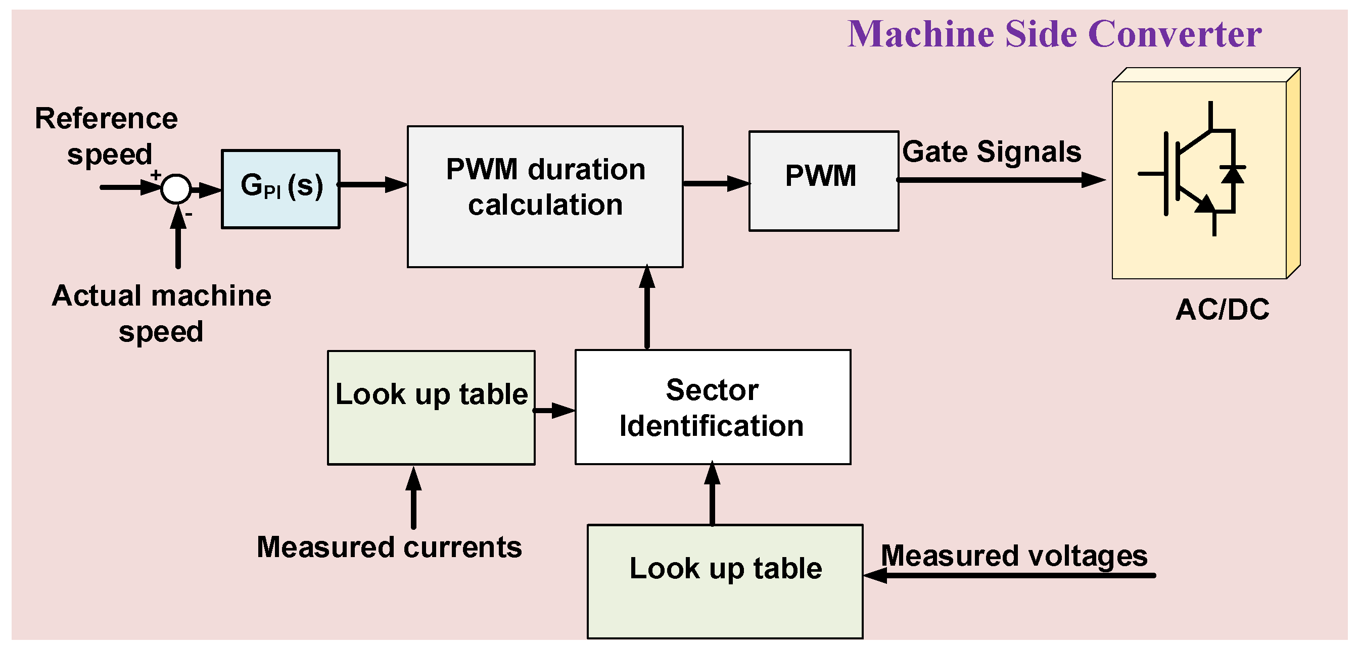
In [61], a novel predictive direct control method has been presented to reduce the number of the required PI controllers while achieving the same advantages of fixed switching frequency controllers and increasing the speed of the overall control system. The work employs the surface permanent magnet synchronous machine as an electric generator of the WEC and targets the smoothing of the active and reactive power control. The block diagram of the control system is shown in Figure 14. Another benefit of the proposed controller is its ability to reduce the THD of currents flowing into the grid, which will improve the power quality.
The control system developed in [62] is an extension to the controller of [61] to enable using the conventional space vector modulation (SVM) technique as a non-linear current source with PMSGs. This can reduce the necessary torque required to oppose the load using the PMSG during occasional strong waves. There are two main contributions of this controller. Firstly, it improves the robustness of the system during transients to a good extent. Secondly, it reduces the required computational time of the control algorithm by around 40%.
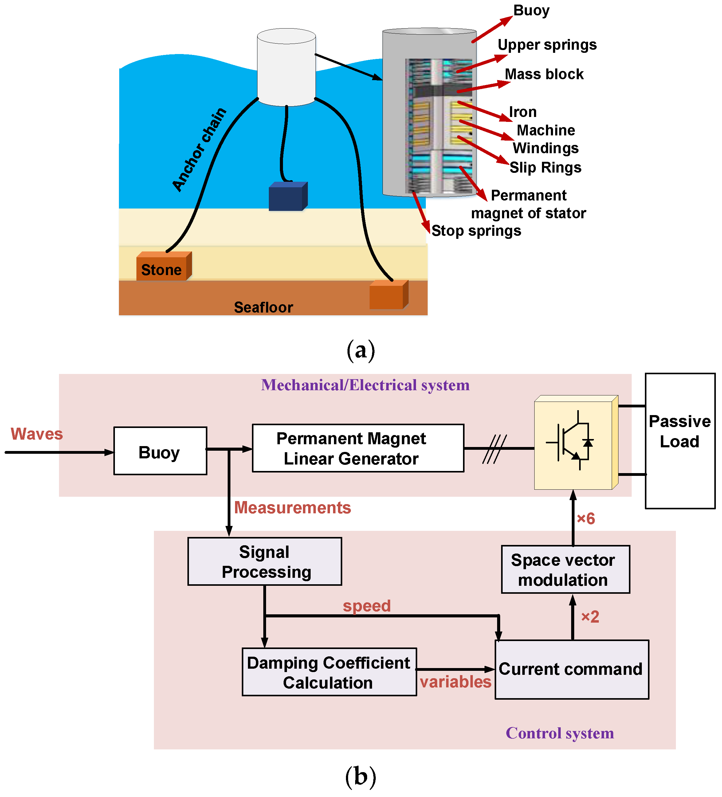
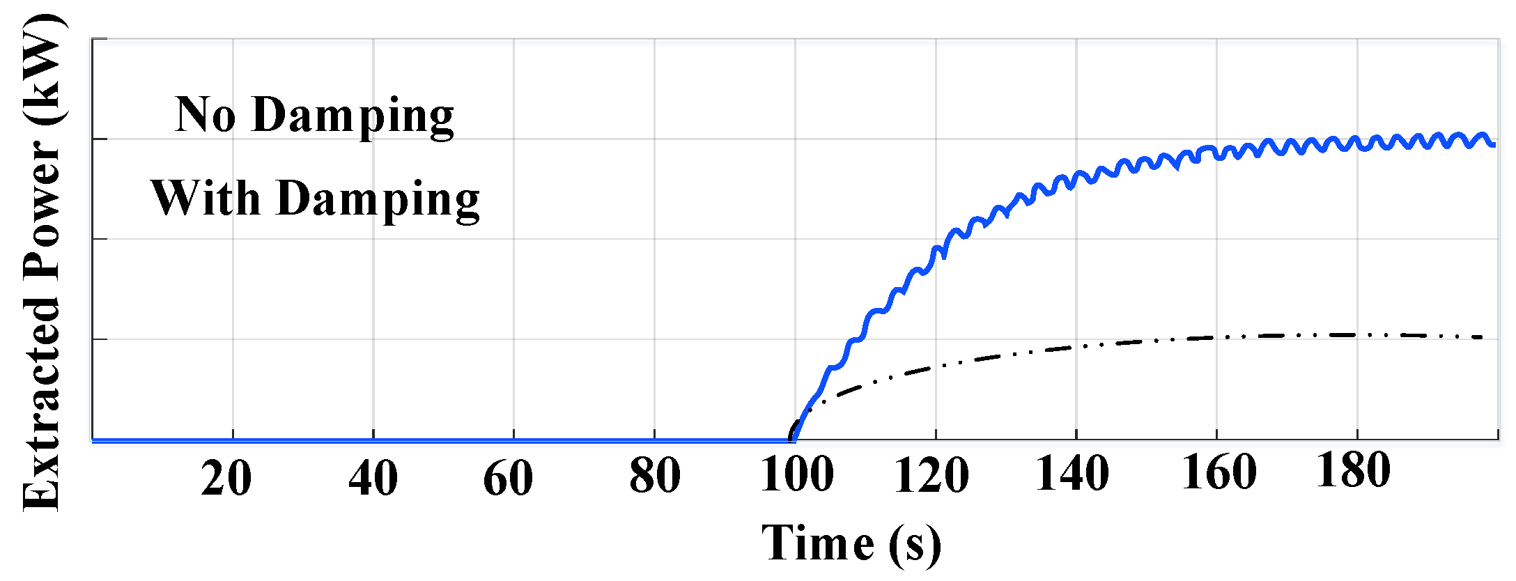
In [63], the WEC system is connected to a passive load rather than the AC grid and a new active phase control method to increase the harvested energy from the WEC has been presented. The developed piecewise velocity control is focused on achieving the maximum power point tracking (MPPT) process to maximize the harvested energy using the active phase control (APC) technique. The proposed control system needs to measure the rotational speed to determine the switching time of the converter. A brief schematic of the system is shown in Figure 15. However, the performance of the controller when the system is connected to the AC utility grid has not been discussed and may need further investigation. The work in [64] extends the previous control system and presents a damping control method for linear PMSG-based WEC systems which use a heave-motion mechanism of buoy. The main difference is that the new control system considers connecting the WEC to the AC grid and proposes a 10 kW test bed for the experiment, which is beneficial to the research efforts in this area. However, thorough discussions about the effect of grid connection are not presented. The presented control is able to increase the operating range of the WEC systems and to improve the control speed during transients. As shown in Figure 16, the control system in [64] was able to increase the extracted power significantly when compared without considering the damping value.
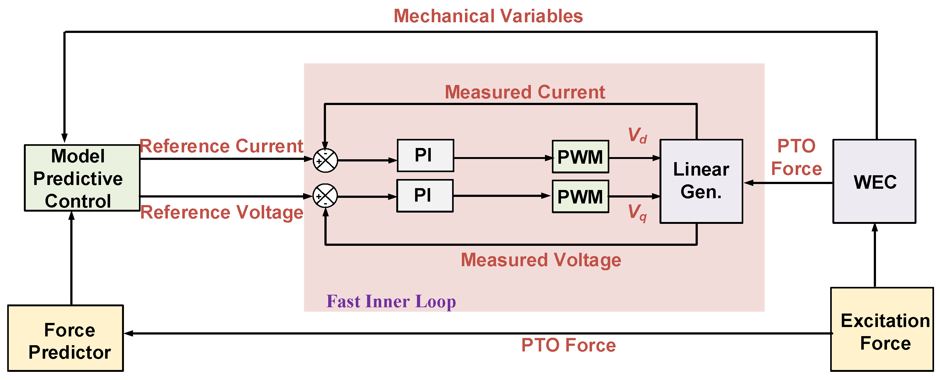
In [65], the work considered WEC systems based on arrays of point absorbers connected to linear permanent magnet generators when they are connected to the grid via back-to-back AC/DC/AC converters. The presented economic model predictive control (MPC) is employed to improve the robustness of the control system. An interesting performance comparison between centralized and decentralized MPCs has been presented to show the advantages and disadvantages of each. An interesting study about the control of the electrical power quality (EPQ) has been presented which points out that, although increasing the average power of the WEC array is an achievement, the low average to peak power ratio can create another problem. This is because the instantaneous WEC-extracted electrical power should be constant at high power levels to avoid the voltage and current fluctuations. These fluctuations can affect the power quality as well as may degrade the stability, especially when the system is connected to weak grids. As one may notice, the latest problem is overlooked by the majority of researchers working in this area. Thus, more analyses and discussions about this and similar problems should be considered in the literature of the WEC systems. Figure 17 shows the proposed control system.
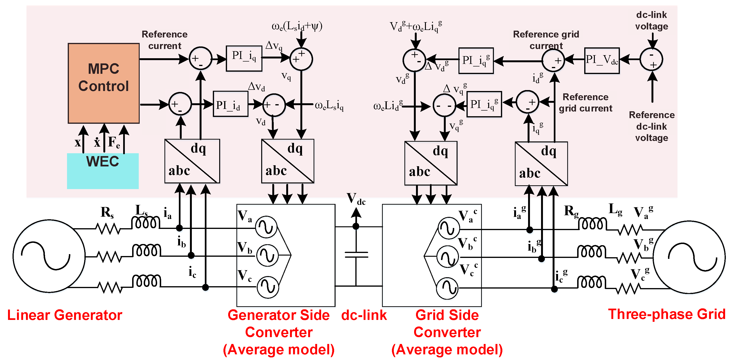
In [66], another control strategy based on MPC has been presented for the point absorbers with direct drive linear regulators considering the losses in the cables and wires to increase the power harvested from the WEC system, see Figure 18. The results in the paper show that including the copper losses in the control algorithm which is based on MPC can improve the performance of the system in terms of controllability and power prediction, which will in turn increase the energy harvested from the WEC system. However, the accuracy of the effect of this control algorithm on the real performance of the AC/DC/AC converter is questioned because the paper used the average model of the converter and, therefore, it neglected the instantaneous behavior.
In [67], the MPC has been extended to include the power losses in the cables as well as the electric generator. The work also considered the WEC system trip limitations and compared the results with the conventional control techniques. The work suggested that the optimum performance will be achieved when the proposed control strategy is used along with compromising the velocity of the oscillating device. In this way, the maximum active power can be generated from the WEC system. The contributions of the publications which employed AC/DC/AC converters for WEC systems are summarized in Table 1.

3.2. Modular and Cascaded Configurations

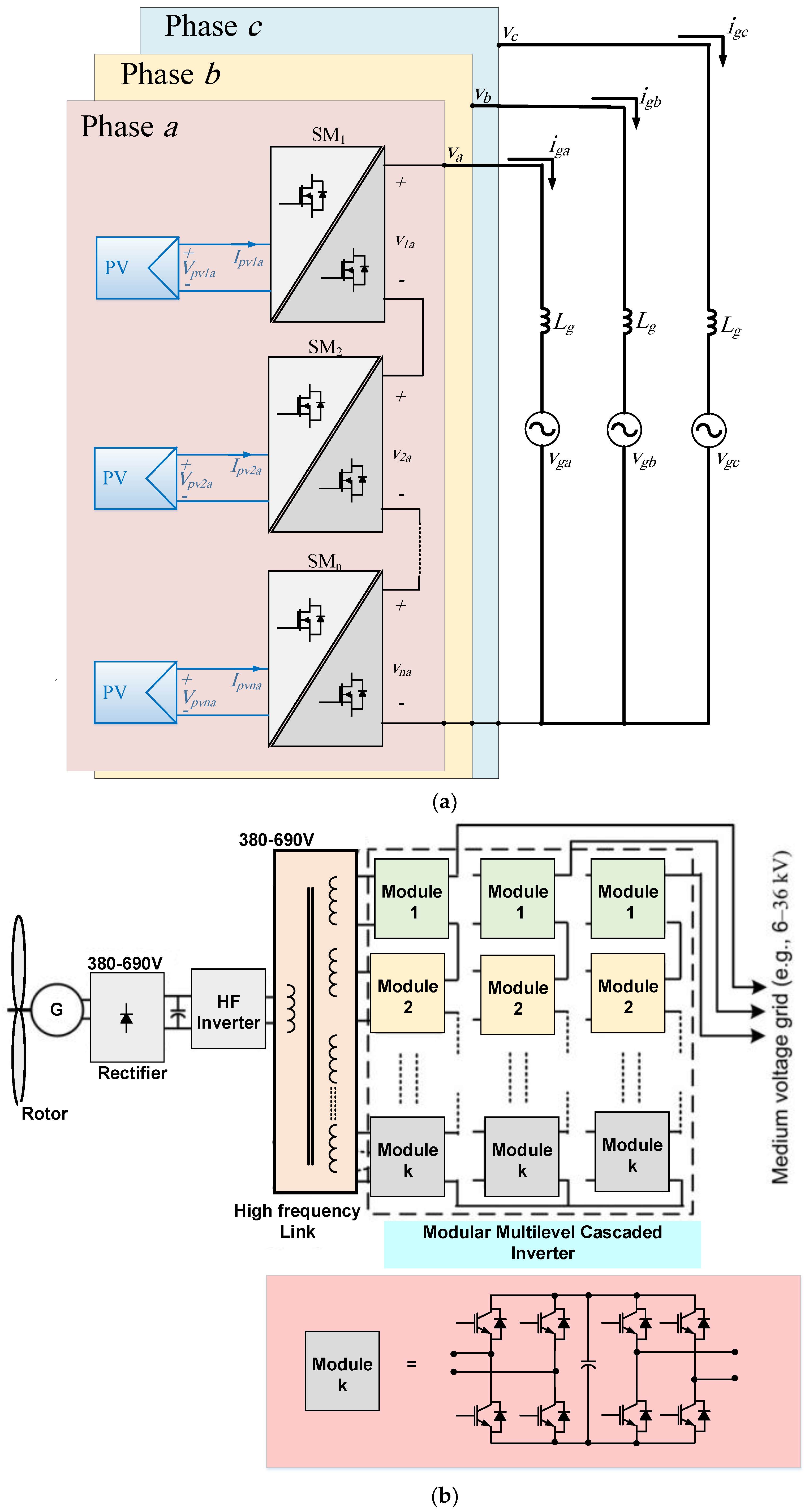
Several research papers considered the design and the control of modular and cascaded configurations instead of the conventional back-to-back converter in different RESs including PV and WTs [68,69,70,71,72,73,74,75,76,77,78,79,80]. Taking the large-scale PV (LSPV) systems, for example, modular converters emerged as a promising candidate where the power conversion stage is formed from several submodules (SMs) instead of one bulky centralized power converter. These modular converters can provide several advantages for the LSPV plants. The modular structure can increase the harvested energy from the PV modules because individual MPPT controllers can be employed on the PV module’s level. Decentralizing the power converter stage will provide modularity and scalability so the LSPV system can generate high power using small semiconductor devices. This also means that, for any partial fault in few SMs, the LSPV system can remain in service with the proper control, which bypasses the faulted SMs. If the employed SM’s converter has an embedded high-frequency transformer (HFT), the bulky line-transformer which connects the LSPV system to the MV grid can be eliminated, which saves massive weight, cost, and volume. The modular multilevel converter (MMC) has dominated the wind systems for the last few decades. Other cascaded modular topologies such as cascaded converters with high- and medium-frequency transformer links are employed for direct grid integration of WT systems. Examples for modular converters for LSPV and WT systems are shown in Figure 19.
The motivation for employing these systems in wave energy applications is that most WEC systems comprise several turbines connected to electrical generators in the form of arrays and are then connected to the grid to inject the resultant electrical power, which is in the range of megawatts. Employing modular converters in such structures will introduce lower harmonic distortion, smaller grid filters, lower dv/dt across the semiconductor switches, and smaller transformers will be needed at the output side. Because this transformation has already occurred in the other RESs, it will be beneficial to study and investigate this in the field of WECs.
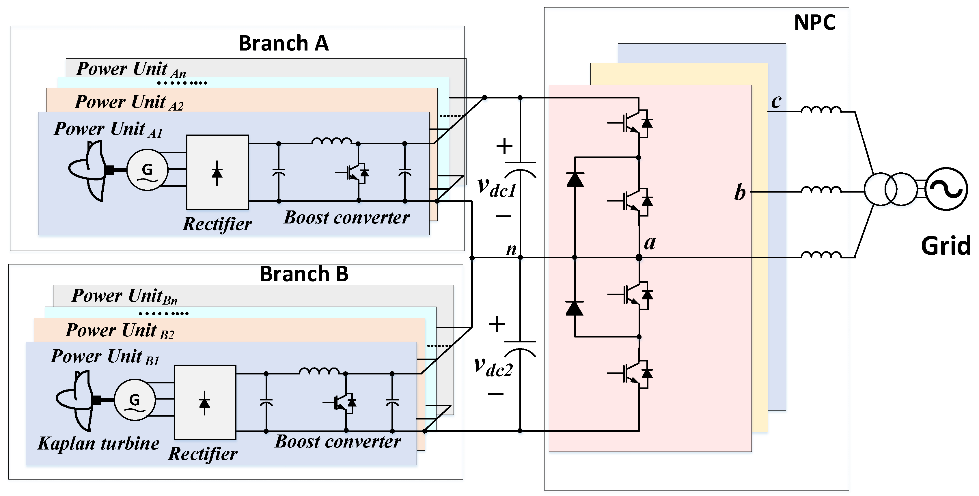
In [81], a new modular configuration has been presented based on PMSG followed by boost converters to build the DC-link of the system. The inverter side is composed of a neutral point clamped (NPC) multilevel converter. As shown in Figure 20, several power units are connected in parallel to increase the harvested power from the Kaplan turbines. Each Kaplan turbine is connected to a PMSG followed by a full diode bridge to rectify the generator three-phase voltage. The boost converter will increase this voltage and control it to match the output DC-link voltage in the middle stage. There are two stages of these blocks to form the upper and lower arms of the NPC inverter.
The NPC then will generate the three-phase output voltage and current and the power will be injected into the grid. A step-up transformer is required to match the output of the NPC to the medium voltage (MV) grid. From the control point of view, the system employed a simple control scheme based on classical PI regulators. The presented results show that the configuration can manage the power generating unit and harvest the maximum energy from the WEC along with controlling the voltage of the middle stage across the DC-link capacitor. However, the paper considered that all WEC are generating the same amount of power and the PMSGs of the units are identical, which is not practical. Additionally, because the power units have been connected in parallel, it is not possible to increase the DC-link voltage above a few hundred volts. Because the NPC is one of the buck-type DC/AC inverters, the AC output voltage of the system will be in the low voltage (LV) range and, therefore, a step-up transformer is necessary to connect the system to the MV network. This opposes the main target of introducing modular power converters in the context of WEC systems.
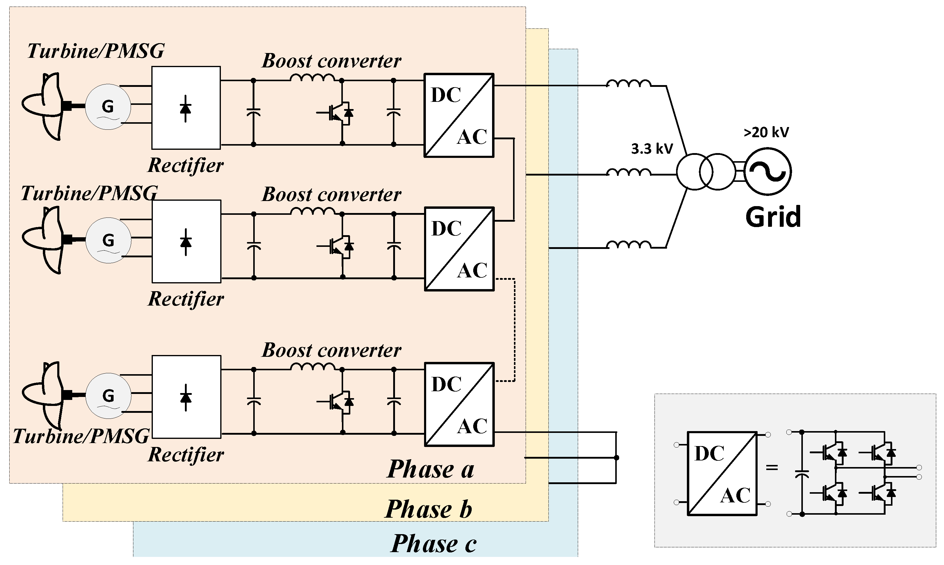
Another modular structure based on the cascaded H-bridge (CHB) converter is presented in [82], as shown in Figure 21. The proposed converter is designed by connecting CHB converters in series parallel combination to replace the conventional back-to-back structure. Using multiple units at low power will improve the modularity, scalability, controllability, and power losses. Because the voltages across the semiconductor switches are lower, fast switches such as Silicon Carbide (SiC) or Gallium Nitride (GaN) devices can be used to improve the efficiency. The output voltage of the system is multilevel and, therefore, the THD is lower and the power quality is improved.
The control scheme presented in [81] depends on classical PI control loops. The outer loop controls the DC-link voltage of each module while the inner loop controls the total output current of the system. Although the control scheme shows how each CHB module is controlled individually, it does not explain how the individual modules are controlled all together. It is not clear how the overall system will be controlled, and a system-level control should have been presented in more detail. The operation is shown and tested when the rotor speed is constant and tracking a set reference value. However, the actual speed of the rotor in a practical WEC system is varying with time and, therefore, the results should have considered this issue. Overall, the presented cascaded topology is promising as it can offer better controllability and performance of WEC systems and the work needs more attention as it can be considered as an important starting point for further research efforts.
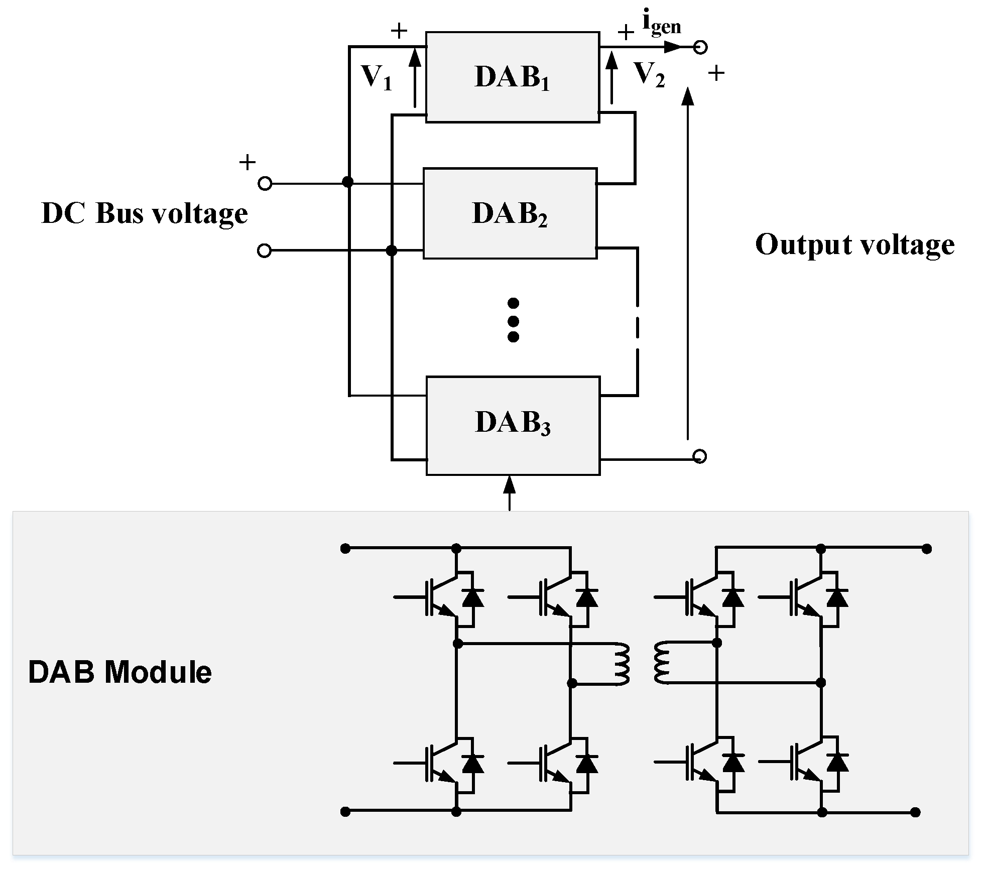
The work in [83] investigates the feasibility of dual active bridge (DAB) modules for energy extraction of dielectric electroactive polymer WEC systems. The DAB modules are connected in input-parallel output-series (IPOS) configuration as shown in Figure 22. In this way, the output voltage can be boosted to meet the medium voltage level. The work presented a hybrid modulation scheme based on variable frequency modulation to increase the voltage range. The paper proposed the mathematical analysis for calculating the power losses and hence the efficiency of the DAB-based system. However, the paper has not considered the generator side of the converter and did not study the effect of the wave cycle or the real generator voltages and currents on the performance of the proposed system.
Table 2 summarizes the contribution of the research publications that focused on employing modular converters for WEC systems. It can be noticed that, unlike other renewable sources, the modular converters have not been discussed thoroughly in the field of WECs yet.

3.3. Matrix Converter

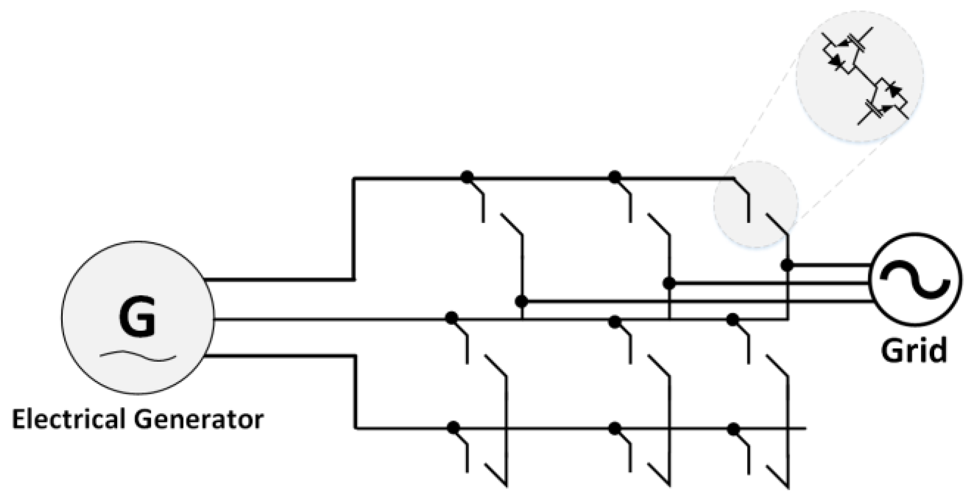
Unlike the other converters which have DC-link capacitors or inductors between the input and output sides, the matrix converter has direct AC/AC connection without any buffer in between and has been employed mainly in permanent magnet synchronous motor (PMSM) applications [84]. As shown in Figure 23, the generator voltages and currents are modulated by a matrix of devices composed of two series switches connected in opposite directions with their antiparallel diodes. The matrix converter has not experienced a great success in the field of other renewable systems such wind or solar PV due to its complex control and the absence of a boosting stage because there is no DC-link [85]. However, the absence of large electrolytic capacitors, which decrease the reliability of the power converters, adding to the lifetime of the RESs, can be considered as one of its advantages.

4. Discussion

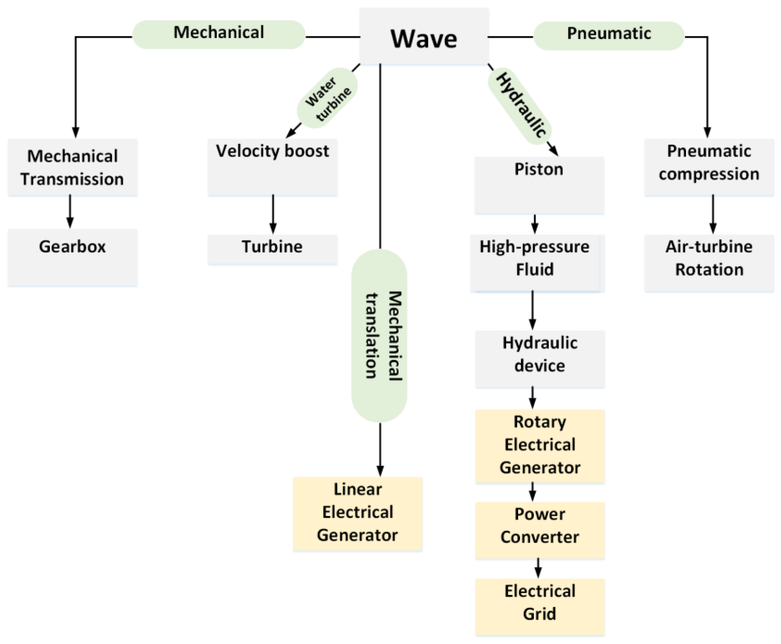
The wave-to-wire power conversion mechanisms require many different mechanical, aeronautical, electrical, and electronic subsystems in order to harvest the energy of the waves and convert it to electricity. Until present, the optimum methods for WEC energy harvesting have not been found and confirmed at least from the electrical point of view. Figure 24 shows the main power take-off techniques while the electrical blocks are shown highlighted in yellow. The performance of any OES including the WEC is determined by the performance of the mechanical conversion stage and energy capturing mechanisms (such as valves, ducts, and turbines), then the mechanical to electrical sub-system (such as the electrical generator), followed by the electrical-to-electrical sub-system (power electronic converters). There are technical challenges for maximising the efficiency and the performance of the electrical sub-systems such as the mismatch between the wave frequency and the desired frequency of the produced electricity, resonance currents in the power converters and the generator, resultant undesired harmonics, and unbalanced voltages and currents due to the connection to weak grids.
The overall efficiency of a real WEC system has been always lower than the theoretical predicted efficiency in the literature because the previous publications focused on the primary mechanical mechanisms in order to prove the concept and improve their performance. WEC designers have focused on developing techniques to extract the energy from the wave to the devices and optimize this energy in the best possible way. However, the same efforts have not been conducted to optimize the energy transfer from the device to the grid. Because these mechanisms are mature now, it is important to explore, validate, and then optimize the electrical systems.
The main two electrical sub-systems of a WEC are the electrical generators and the power electronic converters. Due to an obvious similarity between ocean wave and wind power, it seems that the WEC developers have been influenced by the wind turbine systems when they designed the electrical system of the WECs. Therefore, the PMSGs and DFIGs are the most common generators in this application, which have been well-established in WT systems. The PMSG has a very high efficiency, which can exceed 95%, while the DFIG is preferred in wind systems due to the fact that the associated power converters do not need to handle the full transferred power because the DFIG stator will be directly connected to the electricity grid while the rotor is controlled by power converters and, hence, they can be made smaller in size [85].
Similar to the wind systems, the back-to-back AC/DC/AC power converter has been the most common topology in the WEC systems. However, because of the time-variant nature of the ocean’s waves, the DC-link of this power converter needs large capacitor to smooth the DC-link voltage. To give an example, a 100 kW WEC requires a DC-link capacitor of around 320 mF, which is a huge value and, therefore, may be not available in the market. Additionally, large electrolytic capacitors are the main source of failure in power converters and reduce the reliability significantly especially with increasing voltage and temperatures [86,87]. Most of the present AC/DC/AC topologies presented for WECs are centralized systems, which means that, if there is a fault, the full system will be out of service until this fault is removed. There are some starting research efforts to modularize the WEC converters presented and explained in the previous sections, which can improve the performance, increase the efficiency, and increase the reliability of the WEC systems. However, these research trials are still in their infancy and need more validation to reach the commercialization stage.
Table 3 summarizes the power converters, electrical machines, and control algorithms used in WEC applications. It can be viewed that the conventional AC/DC/AC converter is still dominating the WEC research and industry. This is because of its simplicity and maturity, even if other converters may have better efficiency and fault ride-through. It can be noticed also that there is little research work on OT systems from the electrical point of view, although they are capable of generating power in the range of MW. The modular power electronic configurations are suitable for OT WECs and, therefore, it is an open area for more research. From the machines’ perspective, permanent magnet linear or synchronous machines are dominating the WEC research work due to their simplicity. However, DFIG are known for their better performance and lower losses and cost and, therefore, may need to be further explored in the context of WEC systems.

5. Conclusions

The paper reviewed and highlighted the main power electronic converters employed in WEC systems and presented the main considerations taken to design the electrical sub-systems. The study has shown that the present WEC power conversion technology is still influenced by the wind systems, which may not be the optimum solution, and needs to be tweaked to meet the WEC requirements. It is difficult to reach the theoretical efficiency and performance of the power converters in real practice because a lot of conditions are not considered while conducting the experiments. Moreover, the private companies who are active in the field of wave systems do not share their results with the scientific community because of commercial reasons and hence it becomes difficult for researchers to include the real conditions and challenges in their analyses and experiments.
When looking at the present literature, one finds that the researchers who are focusing on the mechanical aspects of the WEC systems and the associated energy capturing mechanisms are working apart from considering the electrical systems and vice versa. It is obvious now that more interdisciplinary research efforts between mechanical, electrical, and control engineers are required to achieve mature research in WEC systems.

Author Contributions

Conceptualization, A.D. and G.A.A.; methodology, A.D. and G.A.A.; software, A.D.; validation, A.D. and G.A.A.; formal analysis, A.D. and G.A.A.; investigation, A.D. and G.A.A.; resources, A.D. and G.A.A.; data curation, A.D.; writing-original draft preparation, A.D.; writing-review and editing, A.D. and G.A.A.; visualization, A.D. and G.A.A.; supervision, A.D. and G.A.A.; project administration, A.D.; funding acquisition, A.D. All authors have read and agreed to the published version of the manuscript.

Funding

This research received no external funding.

Institutional Review Board Statement

Not applicable.

Informed Consent Statement

Not applicable.

Data Availability Statement

Not applicable.

Conflicts of Interest

The authors declare no conflict of interest.

References

  1. von Jouanne, A.; Brekken, T.K.A. Ocean and Geothermal Energy Systems. Proc. IEEE 2017, 105, 2147–2165. [Google Scholar] [CrossRef]
  2. Tousif, S.M.R.; Taslim, S.M.B. Producing electricity from geothermal energy. In Proceedings of the 2011 10th International Conference on Environment and Electrical Engineering, Rome, Italy, 8–11 May 2011; pp. 1–4. [Google Scholar]
  3. Burhanudin, J.; Abu Hasim, A.S.; Ishak, A.M.; Dardin, S.S. A Review of Power Electronics for Nearshore Wave Energy Converter Applications. IEEE Access 2022, 10, 16670–16680. [Google Scholar] [CrossRef]
  4. CC Energy. CETO. Available online: https://www.carnegiece.com/wave/ (accessed on 24 May 2019).
  5. Blaabjerg, F.; Liu, H.; Loh, P.C. Marine energy generation systems and related monitoring and control. IEEE Instrum. Meas. Mag. 2014, 17, 27–32. [Google Scholar] [CrossRef]
  6. IRENA. Future of Solar Photovoltaic: Deployment, Investment, Technology, Grid Integration and Socio-Economic Aspects (A Global Energy Transformation: Paper). 2019. Available online: https://www.irena.org/-/media/Files/IRENA/Agency/Publication/2019/Nov/IRENA_Future_of_Solar_PV_2019.pdf (accessed on 16 October 2022).
  7. IREA. Renewable Power Generation Costs in 2020. 2020. Available online: https://www.irena.org/publications/2021/Jun/Renewable-Power-Costs-in-2020 (accessed on 16 October 2022).
  8. Vining, J.G.; Muetze, A. Economic factors and incentives for ocean wave energy conversion. IEEE Trans. Ind. Appl. 2009, 45, 547–554. [Google Scholar] [CrossRef]
  9. Teillant, B.; Costello, R.; Weber, J.; Ringwood, J. Productivity and economic assessment of wave energy projects through operational simulations. Renew. Energy 2012, 48, 220–230. [Google Scholar] [CrossRef] [Green Version]
  10. DiPippo, R. Geothermal Power Plants, Principles, Applications, Case Studies and Environmental Impact, 2nd ed.; Elsevier: Butterworth-Heinemann, Oxford, UK, 2008. [Google Scholar]
  11. Schmela, M.; Döring, T. Global Market Outlook for Solar Power 2017–2021; Solar-Power Europe: Brussels, Belgium, 2017. [Google Scholar]
  12. REN21. Renewables 2021 Global Status Report. Available online: https://www.ren21.net/wp-content/uploads/2019/05/gsr_2020_full_report_en.pdf (accessed on 16 October 2022).
  13. Kai, L.Y.; Sarip, S.; Kaidi, H.M.; Ardila-Rey, J.A.; Samsuddin, N.M.; Muhtazaruddin, M.N.; Muhammad-Sukki, F.; Aziz, S.A. Current Status and Possible Future Applications of Marine Current Energy Devices in Malaysia: A Review. IEEE Access 2021, 9, 86869–86888. [Google Scholar] [CrossRef]
  14. Zhou, Z.; Scuiller, F.; Charpentier, J.F.; Benbouzid, M.; Tang, T. An up-to-date review of large marine tidal current turbine technologies. In Proceedings of the 2014 International Power Electronics and Application Conference and Exposition, Shanghai, China, 5–8 November 2014; pp. 480–484. [Google Scholar] [CrossRef]
  15. Chappell, B. Greece Says Its Entire Electrical Grid Ran on 100% Renewables for the First Time. Npr, 13 October 2022. Available online: https://www.npr.org/2022/10/13/1128737392/greece-renewable-energy-electrical-grid (accessed on 16 October 2022).
  16. Shek, J.K.H.; Macpherson, D.E.; Mueller, M.A. Power conversion for wave energy applications. In Proceedings of the 5th IET International Conference on Power Electronics, Machines and Drives (PEMD 2010), Brighton, UK, 19–21 April 2010; pp. 1–6. [Google Scholar] [CrossRef]
  17. IEA. Key World Energy statistics 2021. Available online: https://iea.blob.core.windows.net/assets/52f66a88-0b63-4ad2-94a5-29d36e864b82/KeyWorldEnergyStatistics2021.pdf (accessed on 16 October 2022).
  18. International Energy Agency-Ocean Energy Systems (IEA-OES) Annual Report. 2021. Available online: https://www.ocean-energy-systems.org/about-us/annual-report/ (accessed on 16 October 2022).
  19. Halamay, D.A.; Brekken, T.K.A.; Simmons, A.; McArthur, S. Reserve requirement impacts of large-scale integration of wind, solar, and ocean wave power generation. IEEE Trans. Sustain. Energy 2011, 2, 321–328. [Google Scholar] [CrossRef]
  20. García-Medina, G.; Özkan-Haller, H.T.; Ruggiero, P. Wave resource assessment in Oregon and southwest Washington, USA. Renew. Energy 2014, 64, 203–214. [Google Scholar] [CrossRef]
  21. Electric Power Research Institute. Mapping and Assessment of the United States Ocean Wave Energy Resource; Electric Power Research Institute: Washington, DC, USA, 2011; p. 1024637. Available online: https://www.osti.gov/servlets/purl/1060943 (accessed on 16 October 2022).
  22. Energy Information Administration. Annual Energy Outlook 2016 with Projections to 2040; Energy Information Administration: Washington, DC, USA, 2016. [Google Scholar]
  23. Gunn, K.; Stock-Williams, C. Quantifying the global wave power resource. Renew. Energy 2012, 44, 294–304. [Google Scholar] [CrossRef]
  24. Pelc, R.; Fujita, R.M. Renewable energy from the ocean. Mar. Policy 2022, 26, 471–479. [Google Scholar] [CrossRef]
  25. Grotelüschen, F. Scientists Race to Develop Floating Wind Farms. Deutsche Welle. Available online: http://www.dw.de/scientists-race-to-develop-floating-wind-farms/a-16540081 (accessed on 16 October 2022).
  26. Boake, C.B.; Whittaker, T.J.T.; Folley, M.; Ellen, H. Overview and initial operational experience of the LIMPET wave energy plant. In Proceedings of the Twelfth International Offshore and Polar Engineering Conference, Kitakyushu, Japan, 26–31 May 2002; Volume 3, p. 586594. [Google Scholar]
  27. De Falcão, A.F.O. Wave energy utilization: A review of the technologies. Renew. Sustain. Energy Rev. 2010, 14, 899–918. [Google Scholar] [CrossRef]
  28. Dalton, G.J.; Alcorn, R.; Lewis, T. Case study feasibility analysis of the pelamis wave energy convertor in Ireland, Portugal and North America. Renew. Energy 2010, 35, 443–455. [Google Scholar] [CrossRef]
  29. The European Commission. Islay Limpet Wave Power Plant; Queen’s University Belfast: Belfast, UK, 2002. Available online: https://tethys.pnnl.gov/sites/default/files/publications/Islay_LIMPET_Report.pdf (accessed on 16 October 2022).
  30. Penalba, M.; Ringwood, J.V. A Review of Wave-to-Wire Models for Wave Energy Converters. Energies 2016, 9, 506. [Google Scholar] [CrossRef] [Green Version]
  31. Amundarain, M.; Alberdi, M.; Garrido, A.J.; Garrido, I.; Maseda, J. Wave energy plants: Control strategies for avoiding the stalling behaviour in the Wells turbine. Renew. Energy 2010, 35, 2639–2648. [Google Scholar] [CrossRef]
  32. Carroll, C.; and Bell, M. Wave Energy Converters Utilizing Pressure Differences. U.S. Patent 6 933 623, 23 August 2005. [Google Scholar]
  33. Jarocki, D. Wave energy converter performance modeling and cost of electricity asessment. In Proceedings of the ASME 2010 International Mechanical Engineering Congress and Exposition, Vancouver, BC, Canada, 12–18 November 2010. [Google Scholar]
  34. Dewhurst, T.; Sivakumar, S. Wave-to-wire modeling and simulation of a wave energy converter for off-grid and micro-grid applications. In Proceedings of the OCEANS 2018 MTS/IEEE Charleston, Charleston, SC, USA, 22–25 October 2018; p. 18. [Google Scholar]
  35. Multon, B. Marine Renewable Energy Handbook; Wiley: New York, NY, USA, 2013. [Google Scholar]
  36. Drew, B.; Plummer, A.; Sahinkaya, M.N. A review of wave energy converter technology. Proc. Inst. Mech. Eng. A J. Power Energy 2009, 223, 887–902. [Google Scholar] [CrossRef] [Green Version]
  37. Edenhofer, O.; Pichs-Madruga, R.; Sokona, Y.; Seyboth, K.; Kadner, S.; Zwickel, T.; Hansen, G.; Schlömer, S.; von Stechow, C.; Matschoss, P.; et al. Renewable Energy Sources and Climate Change Mitigation: Special Report of the Intergovernmental Panel on Climate Change; Cambridge University Press: Cambridge, UK, 2011. [Google Scholar]
  38. Delmonte, N.; Barater, D.; Giuliani, F.; Cova, P.; Buticchi, G. Review of Oscillating Water Column Converters. IEEE Trans. Ind. Appl. 2016, 52, 1698–1710. [Google Scholar] [CrossRef]
  39. Markets and Martekts. Wave Energy Converter Market by Technology; Market Research Report. Available online: https://www.marketsandmarkets.com/Market-Reports/wave-energy-market-217091216.html (accessed on 16 October 2022).
  40. Chen, Z.; Guerrero, J.M.; Blaabjerg, F. A review of the state of the art of power electronics for wind turbines. IEEE Trans. Power Electron. 2009, 24, 1859–1875. [Google Scholar] [CrossRef]
  41. Bediaga, I.; Mendizabal, X.; Arnaiz, A.; Munoa, J. Ball bearing damage detection using traditional signal processing algorithms. IEEE Instrum. Meas. Mag. 2013, 16, 20–25. [Google Scholar] [CrossRef]
  42. Darwish, A.; Abdelsalam, A.K.; Massoud, A.M.; Ahmed, S. Single phase grid connected curent source inverter: Mitigation of oscillating power effect on the grid current. In Proceedings of the IET Conference on Renewable Power Generation (RPG 2011), Edinburgh, UK, 6–8 September 2011; pp. 1–7. [Google Scholar] [CrossRef]
  43. Darwish, A.; Holliday, D.; Finney, S. Operation and control design of an input-series–input-parallel–output-series conversion scheme for offshore DC wind systems. IET Power Electron. 2017, 10, 2092–2103. [Google Scholar] [CrossRef] [Green Version]
  44. Darwish, A.; Elserougi, A.; Abdel-Khalik, A.S.; Ahmed, S.; Massoud, A.; Holliday, D.; Williams, B.W. A single-stage three-phase DC/AC inverter based on Cuk converter for PV application. In Proceedings of the 2013 7th IEEE GCC Conference and Exhibition (GCC), Doha, Qatar, 17–20 November 2013; pp. 384–389. [Google Scholar] [CrossRef] [Green Version]
  45. Blaabjerg, F.; Teodorescu, R.; Liserre, M.; Timbus, A.V. Overview of control and grid synchronization for distributed power generation systems. IEEE Trans. Ind. Electron. 2006, 53, 1398–1409. [Google Scholar] [CrossRef] [Green Version]
  46. Badawy, A.D. Current Source dc-dc and dc-ac Converters with Continuous Energy Flow. Ph.D. Thesis, University of Strathclyde, Glasgow, UK, 2015. [Google Scholar]
  47. Darwish, A.; Abdel-Khalik, A.; Elserougi, A.; Ahmed, S.; Massoud, A. Fault current contribution scenarios for grid-connected voltage source inverter-based distributed generation with an LCL filter. Electr. Power Syst. Res. 2013, 104, 93–103. [Google Scholar] [CrossRef]
  48. Salter, S.H.; Taylor, J.R.M.; Caldwell, N.J. Power conversion mechanisms for wave energy. Proc. Inst. Mech. Eng. Part M J. Eng. Marit. Environ. 2002, 216, 1–27. [Google Scholar] [CrossRef]
  49. EAmon, A.; Brekken, T.K.A.; Schacher, A.A. Maximum Power Point Tracking for Ocean Wave Energy Conversion. IEEE Trans. Ind. Appl. 2012, 48, 1079–1086. [Google Scholar] [CrossRef]
  50. Darwish, A.; Elgenedy, M.A. Current-Source Modular Medium-Voltage Grid-Connected System with High-Frequency Isolation for Photovoltaic Applications. IEEE Trans. Energy Convers. 2019, 34, 255–266. [Google Scholar] [CrossRef] [Green Version]
  51. Ibrahim, A.; Philip, A.G.; Derrick, H.; Williams, B.W. Modified back-to-back current source converter and its application to wind energy conversion systems. IET Power Electron. 2015, 8, 103–111, ISSN 1755-4535. [Google Scholar]
  52. Simonetti, D.S.L.; Amorim, A.E.A.; Oliveira, F.D.C. Chapter 15—Doubly Fed Induction Generator in Wind Energy Conversion Systems. In Advances in Renewable Energies and Power Technologies; Yahyaoui, I., Ed.; Elsevier: Amsterdam, The Netherlands, 2018; pp. 461–490. [Google Scholar]
  53. Hazra, S.; Bhattacharya, S. Modeling and emulation of a rotating paddle typewave energy converter. IEEE Trans. Energy Convers. 2018, 33, 594–604. [Google Scholar] [CrossRef]
  54. M’zoughi, F.; Bouallegue, S.; Garrido, A.J.; Garrido, I.; Ayadi, M. Stalling-free control strategies for power generation plants. IEEE Trans. Energy Convers. 2018, 33, 209–222. [Google Scholar] [CrossRef]
  55. Zarei, M.E.; Ramirez, D.; Nicolas, C.V.; Arribas, J.R. Three-Phase Four-Switch Converter for SPMS Generators Based on Model Predictive Current Control for Wave Energy Applications. IEEE Trans. Power Electron. 2020, 35, 289–302. [Google Scholar] [CrossRef]
  56. McDonald, S.P.; Baker, N.J.; Espinoza, M.; Pickert, V. Power-takeoff topology comparison for a wave energy converter. J. Eng. 2019, 2019, 5012–5017. [Google Scholar] [CrossRef]
  57. McDonald, S.P.; Baker, N.J.; Pickert, V. High-frequency current source converter for a direct drive powertrain in a wave energy converter. J. Eng. 2019, 2019, 3629–3633. [Google Scholar] [CrossRef]
  58. Hillis, A.; Whitlam, C.; Brask, A.; Chapman, J.; Plummer, A. Active control for multi-degree-of-freedom wave energy converters with load limiting. Renew. Energy 2020, 159, 1177–1187. [Google Scholar] [CrossRef]
  59. Jama, M.; Wahyudie, A.; Mekhilef, S. Wave excitation force estimation using an electrical-based extended Kalman lter for point absorber wave energy converters. IEEE Access 2020, 8, 49823–49836. [Google Scholar] [CrossRef]
  60. Hasanien, H.M. Transient Stability Augmentation of a Wave Energy Conversion System Using a Water Cycle Algorithm-Based Multiobjective Optimal Control Strategy. IEEE Trans. Ind. Inform. 2019, 15, 3411–3419. [Google Scholar] [CrossRef]
  61. Zarei, M.E.; Ramirez, D.; Veganzones, C.; Rodriguez, J. Predictive Direct Control of SPMS Generators Applied to the Machine Side Converter of an OWC Power Plant. IEEE Trans. Power Electron. 2020, 35, 6719–6731. [Google Scholar] [CrossRef]
  62. Ramirez, D.; Mendonça, H.; Blanco, M.; Martinez, F. Non-linear vector current source for the control of permanent magnet synchronous generators in wave energy applications. IET Renew. Power Gener. 2019, 13, 2409–2417. [Google Scholar] [CrossRef]
  63. Huang, W.; Yang, J. A novel piecewise velocity control method using passivity-based controller for wave energy conversion. IEEE Access 2020, 8, 59029–59043. [Google Scholar] [CrossRef]
  64. Oh, Y.J.; Park, J.S.; Hyon, B.J.; Lee, J. Novel Control Strategy of Wave Energy Converter Using Linear Permanent Magnet Synchronous Generator. IEEE Trans. Appl. Supercond. 2018, 28, 26. [Google Scholar] [CrossRef]
  65. O’Sullivan, A.C.M.; Sheng, W.; Lightbody, G. An Analysis of the Potential Benefits of Centralised Predictive Control for Optimal Electrical Power Generation from Wave Energy Arrays. IEEE Trans. Sustain. Energy 2018, 9, 1761–1771. [Google Scholar] [CrossRef]
  66. Andrade, D.; Jaen, A.G.S.l. Considering linear generator copper losses on model predictive control for a point absorber wave energy converter. Energy Convers. Manag. 2014, 78, 173–183. [Google Scholar] [CrossRef]
  67. De La Villa-Jaén, A.; El Montoya-Andrade, D.; García-Santana, A. Control strategies for point absorbers considering linear generator copper losses and maximum excursion constraints. IEEE Trans. Sustain. Energy 2018, 9, 433–442. [Google Scholar] [CrossRef]
  68. Kazmierkowski, M.P.; Jasinski, M. Power electronics for renewable sea wave energy. In Proceedings of the 2010 12th International Conference on Optimization of Electrical and Electronic Equipment, Brasov, Romania, 20–22 May 2010. [Google Scholar]
  69. Islam, R.; Guo, Y.; Zhu, J. A High-Frequency Link Multilevel Cascaded Medium-Voltage Converter for Direct Grid Integration of Renewable Energy Systems. IEEE Trans. Power Electron. 2014, 29, 4167–4182. [Google Scholar] [CrossRef]
  70. Darwish, A.; Alotaibi, S.; Elgenedy, M.A. Current-Source Single-Phase Module Integrated Inverters for PV Grid-Connected Applications. IEEE Access 2020, 8, 53082–53096. [Google Scholar] [CrossRef]
  71. Niroomand, M.; Esfahani, F.N. Converter technologies for PV systems: A comprehensive review. In Energy Conversion Systems: An Overview; Nova Science Publishers: Hauppauge, NY, USA, 2021. [Google Scholar]
  72. Islam, R.; Mahfuz-Ur-Rahman, A.M.; Muttaqi, K.M.; Sutanto, D. State-of-the-Art of the Medium-Voltage Power Converter Technologies for Grid Integration of Solar Photovoltaic Power Plants. IEEE Trans. Energy Convers. 2019, 34, 372–384. [Google Scholar] [CrossRef]
  73. Bughneda, A.; Salem, M.; Richelli, A.; Ishak, D.; Alatai, S. Review of Multilevel Inverters for PV Energy System Applications. Energies 2021, 14, 1585. [Google Scholar] [CrossRef]
  74. Zhang, X.; Zhao, T.; Mao, W.; Tan, D.; Chang, L. Multilevel Inverters for Grid-Connected Photovoltaic Applications: Examining Emerging Trends. IEEE Power Electron. Mag. 2018, 5, 32–41. [Google Scholar] [CrossRef]
  75. Alotaibi, S.; Darwish, A. Modular Multilevel Converters for Large-Scale Grid-Connected Photovoltaic Systems: A Review. Energies 2021, 14, 6213. [Google Scholar] [CrossRef]
  76. Noman, A.M.; Addoweesh, K.E.; Alabduljabbar, A.A.; Alolah, A.I. Cascaded H-Bridge MLI and Three-Phase Cascaded VSI Topologies for Grid-Connected PV Systems with Distributed MPPT. Int. J. Photoenergy 2019, 2019, 7642919. [Google Scholar] [CrossRef]
  77. Stynski, S.; Grzegorczyk, M.; Sobol, C.; Kot, R. Current Control Strategies for a Star Connected Cascaded H-Bridge Converter Operating as MV-AC to MV-DC Stage of a Solid State Transformer. Energies 2021, 14, 4607. [Google Scholar] [CrossRef]
  78. Lumbreras, D.; Barrios, E.L.; Balda, J.; Navarrete, M.; Gonzalez, R.; Sanchis, P. Medium-Voltage Cascaded Sequential Topology for Large-Scale PV Plants. IEEE Access 2021, 9, 130601–130614. [Google Scholar] [CrossRef]
  79. Gunsal, I.; Stone, D.A.; Foster, M.P. Suppressing Leakage Current for Cascaded H-Bridge Inverters in Renewable Energy and Storage Systems. IEEE Trans. Ind. Electron. 2021, 68, 11035–11043. [Google Scholar] [CrossRef]
  80. Amaral, F.V.; Parreiras, T.M.; Lobato, G.C.; Machado, A.A.P.; Pires, I.A.; Filho, B.D.J.C. Operation of a Grid-Tied Cascaded Multilevel Converter Based on a Forward Solid-State Transformer Under Unbalanced PV Power Generation. IEEE Trans. Ind. Appl. 2018, 54, 5493–5503. [Google Scholar] [CrossRef]
  81. Muller, N.; Kouro, S.; Malinowski, M.; Rojas, C.A.; Jasinski, M.; Estay, G. Medium-Voltage Power Converter Interface for Multigenerator Marine Energy Conversion Systems. IEEE Trans. Ind. Electron. 2017, 64, 1061–1070. [Google Scholar] [CrossRef]
  82. Müller, N.; Kouro, S.; Malinowski, M.; Rivera, S.; Wu, B. Cascaded H-bridge multilevel converter interface for Wave Dragon energy conversion system. In Proceedings of the IECON 2013-39th Annual Conference of the IEEE Industrial Electronics Society, Vienna, Austria, 10–13 November 2013; pp. 6201–6206. [Google Scholar] [CrossRef]
  83. Todorčević, T.; van Kessel, R.; Bauer, P.; Ferreira, J.A. A Modulation Strategy for Wide Voltage Output in DAB-Based DC–DC Modular Multilevel Converter for DEAP Wave Energy Conversion. IEEE J. Emerg. Sel. Top. Power Electron. 2013, 3, 1171–1181. [Google Scholar] [CrossRef]
  84. Khwan-On, S.; De Lillo, L.; Empringham, L.; Wheeler, P.; Gerada, C. Fault-tolerant, matrix converter, permanent magnet synchronous motor drive for open-circuit failures. IET Electr. Power Appl. 2011, 5, 654–667. [Google Scholar] [CrossRef]
  85. Lee, M.J.; Wheeler, P.; Klumpner, C. Space-vector modulated multilevel matrix converter. IEEE Trans. Ind. Electron. 2010, 57, 3385–3394. [Google Scholar] [CrossRef]
  86. Muller, S.; Deicke, M.; De Doncker, R. Doubly fed induction generator systems for wind turbines. IEEE Ind. Appl. Mag. 2002, 8, 26–33. [Google Scholar] [CrossRef]
  87. Alotaibi, S.; Darwish, A.; Ma, X.; Williams, B.W. A new modular three-phase inverter based on sepic-cuk combination converter for photovoltaic applications. In Proceedings of the 9th Renewable Power Generation Conference (RPG Dublin Online 2021), Online Conference, 1–2 March 2021; pp. 259–264. [Google Scholar] [CrossRef]
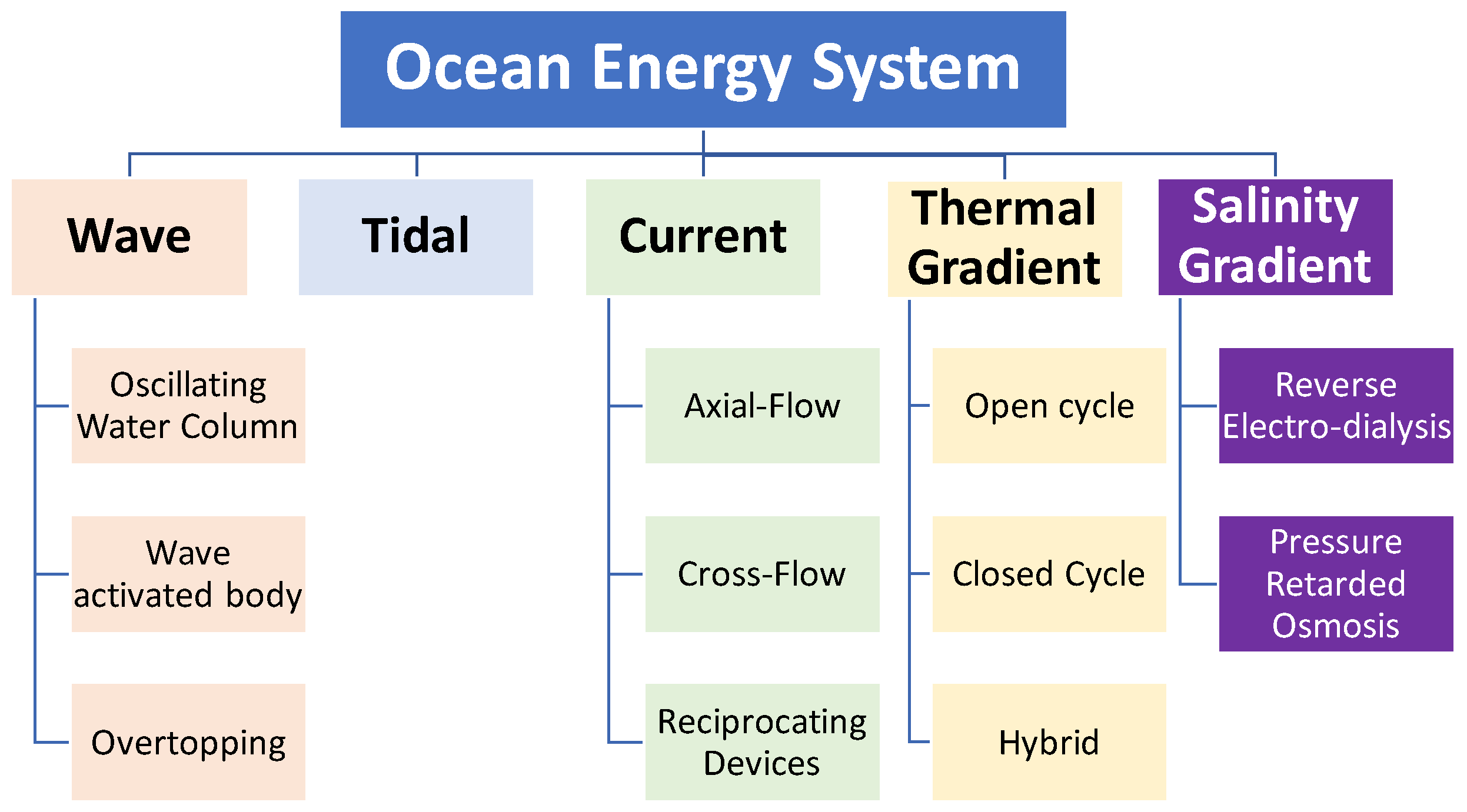
Figure 1. General classification of Ocean Energy Conversion System.
Energies 15 09174 g001
Figure 2. General control structure of Ocean Energy System.
Energies 15 09174 g002
Figure 3. WEC electrical power conversion.
Energies 15 09174 g003
Figure 4. A brief schematic of WEC system.
Energies 15 09174 g004
Figure 5. A brief schematic of WEC system.
Energies 15 09174 g005
Figure 6. Power converters of a paddle-type WEC.
Energies 15 09174 g006
Figure 7. Reproduced results from the paddle-type WEC in [53]. Generator speed: 200 r/min/div and generator no-load voltage: 20 V/div–Time: 1 s/div.
Energies 15 09174 g007
Figure 8. Reproduced results from the paddle-type WEC in [53]. Generator torque: 30 Nm/div and generator output power: 400 W/div–Time: 5 s/div.
Energies 15 09174 g008
Figure 9. Control of Oscillating Water Column-based WEC [54].
Energies 15 09174 g009
Figure 10. Three-phase four-switch converter connected to a WEC system [55].
Energies 15 09174 g010
Figure 11. CSC-based WEC.
Energies 15 09174 g011
Figure 12. Comparison between power losses in WECs based on VSC and CSC [56,57].
Energies 15 09174 g012
Figure 13. PI-based control system in [60].
Energies 15 09174 g013
Figure 14. PI-based control system in [61].
Energies 15 09174 g014
Figure 15. APC Control system in [63]: (a) The mechanical structure and (b) Control system.
Energies 15 09174 g015
Figure 16. Comparison of harvested powers in [64].
Energies 15 09174 g016
Figure 17. MPC control system in [65].
Energies 15 09174 g017
Figure 18. MPC control system in [66].
Energies 15 09174 g018
Figure 19. Modular converters in RES: (a) LSPV and (b) Wind systems.
Energies 15 09174 g019
Figure 20. MV Modular configuration for WEC systems in [81].
Energies 15 09174 g020
Figure 21. CHB Modular configuration for WEC systems in [82].
Energies 15 09174 g021
Figure 22. DAB modular converter in [83].
Energies 15 09174 g022
Figure 23. Matrix Converter.
Energies 15 09174 g023
Figure 24. Wave-to-wire power conversion schemes.
Energies 15 09174 g024
Table 1. Summary of the research publications employing AC/DC/AC converters in WECs.
Ref.ContributionRemarks
[53]
Computing the torque components to obtain an accurate dynamic model of the WEC
Emulating the WEC experimentally by motor/generator set which is controlled by a real-time controller.
Achieving the maximum power point of the WEC.
The effect of the oscillatory shaft speed and torque on the performance of the power converters has not been considered.
Estimations about the efficiency of the converters have not been discussed.
[54]
Employing a DFIG instead of PMSG to decrease the power handled by the machine.
Control strategy can reduce the stalling behavior of the OWC WECs.
Case studies show the ability of the PI-based controllers to achieve MPPT.
The work did not consider the conduction or switching losses of the rotor- or the grid-side converters.
The DC-link voltage and generator’s current behaviors have not been considered.
[55]
Using only four switches for the grid-side converter without losing the current tracking.
Fast dynamic response and good THD
Rotor speed has been considered constant, which is not realistic.
No evaluation for the effect of removing the two switches on the real power losses.
[56]
The first attempt to employ current source converters in the field of WEC systems
Insightful comparisons between the performance of current source converters and conventional voltage source converters
The control algorithm and modulation scheme have not been discussed.
The mathematical equations for power losses have not been presented.
[57]
Minimizing the self-inductance of the current source converters for WEC systems.
Four quadrant operation.
The control algorithm and modulation scheme have not been discussed.
[58]
Improving the controllability of the WEC system by using linear quadratic regulators
Experimental results show an increase in the harvested power
Used the average model of the power electronic converter
No discussion about the power losses and efficiency
[59]
Employing Kalman Filter to estimate the excitation force and floater’s heave displacement
Assumed a passive load rather than an AC grid.
[60]
Employing two double-loop PI controllers to enhance the stability of the WEC system by controlling the AC/DC and DC/AC sides of the converter.
Improving the transient stability
Did not discuss the effect on output power quality or the devices’ power losses.
[61]
Increasing the speed of the predictive direct control
Improved power quality.
Rotor speed is not realistic in the experiments
[62]
Implementing conventional SVM for a non-linear cur-rent source with PMSGs
Improving the robustness of the system during transients
Reducing the required computational time
Power quality is not considered.
[63]
Achieving MPPT to maximize the harvested energy by the APC.
Only measures the rotational speed to determine the switching time of the converter.
WEC system is connected to a passive load rather than the AC grid
[64]
An extension for [63] with grid connection
Power quality is not considered.
[65]
Investigating the power quality thoroughly.
Discussing the effect of connecting WECs to weak grids.
Studies the operation of the overall array without focusing on the in-detail behaviors of the generator and converter
[66]
Including the copper losses in the control algorithm.
Improving the performance of the system in terms of controllability and power prediction
Employed an average model for the AC/DC/AC converter.
[67]
Extending [66] by include the power losses in the cables as well as the electric generator
Employed an average model for the AC/DC/AC converter.
Table 2. Summary of the research publications employing modular converters in WECs.
Ref.ContributionRemarks
[81]
Managing the power generating unit and harvest the maximum energy from the WEC along with controlling the voltage of the middle stage across the DC-link capacitor.
Considered that all WECs are generating the same amount of power and the PMSGs of the units are identical, which is not practical.
The power units are in parallel and it is not possible to increase the DC-link voltage above few hundred volts.
Because the NPC is one of the buck-type DC/AC inverters, the AC output voltage of the system will be in the low voltage (LV) range and, therefore, a step-up transformer is necessary to connect the system to the MV network.
[82]
Using multiple units at low power will improve the modularity, scalability, controllability, and power losses.
Because the voltages across the semiconductor switches are lower, fast switches such as Silicon Carbide (SiC) or Gallium Nitride (GaN) devices can be used to improve the efficiency.
The output voltage of the system is multilevel and, therefore, the THD is lower and the power quality is improved.
Case studies show the ability of the PI-based controllers to achieve MPPT.
Does not explain how the individual modules are controlled all together.
It is not clear how the overall system will be controlled, and a system-level control should have been presented in more detail.
[83]
Providing high voltage boosting ratio so the output voltage can meet the medium voltage level.
Presenting hybrid modulation scheme based on variable frequency modulation to increase the voltage range.
Presenting the mathematical analysis for calculating the power losses and hence the efficiency of the DAB-based system.
Has not considered the generator side of the converter and did not study the effect of the wave cycle or the real generator voltages and currents on the performance of the proposed system.
Table 3. Summary of the power converters, electrical machines, and control algorithms used in WEC applications.
RefWEC TypeElectric GeneratorPower ConverterControl Algorithm
[53]OWCPMSGAC/DC/ACOpen-loop Control
[54] OWCDFIGAC/DC/ACTwo-loop PI Control
[55]OWCPMSGAC/DC/ACModel Predictive Current Control
[56]OWCPMLGCurrent source back-to-backNot considered
[57]OWCPMLGCurrent source back-to-backOpen-loop based on a new SVM
[58]WABNot consideredAC/DC/ACMulti-degree-of-freedom active control
[59]WABPMLGAC/DC/ACElectrical-based extended Kalman filter
[60]WABPMSGAC/DC/ACTwo-loop PI Control
[61]OWCPMSGAC/DC/ACPredictive Direct Control
[62]OWCPMSGAC/DC/ACTwo-loop PI Control
[63]WABPMLGAC/DCPiecewise Velocity Control
[64]WABPMSGAC/DC/ACDamping control strategy
[65]WABPMLGAC/DC/ACModel predictive control
[66]OTPMLGAC/DC/ACModel predictive control
[67]OTPMLGAC/DC/ACModel predictive control
[81]OTPMSGModular back-to-back voltage source converterTwo-loop PI Control
[82]OTPMSGModular Cascaded H-bridgeTwo-loop PI Control
[83]DEAPNot consideredModular DABPI Control
Publisher’s Note: MDPI stays neutral with regard to jurisdictional claims in published maps and institutional affiliations.