Article

A Maximum Power Point Tracker Using the Bald Eagle Search Technique for Grid-Connected Photovoltaic Systems

1
Department of Electrical and Computer Engineering, Sultan Qaboos University, P.O. Box 33, Muscat 123, Oman
2
Sustainable Energy Research Center (SERC), Sultan Qaboos University, P.O. Box 33, Muscat 123, Oman
*
Author to whom correspondence should be addressed.
Energies 2022, 15(23), 9185; https://doi.org/10.3390/en15239185
Submission received: 17 November 2022 / Revised: 30 November 2022 / Accepted: 1 December 2022 / Published: 4 December 2022

Abstract

:
Maximum power point tracker (MPPT) methods work to maximize the output power of a PV system under changes in meteorological conditions. The performance of these methods depends on the complexity of the algorithm and the number of used variable inputs for obtaining the MPP value. Moreover, they oscillate around the MPP in steady-state operations, causing a waste of power and power loss. Moreover, they do not work perfectly for a PV system running under partial shading conditions. Therefore, this paper proposes modifications to the global maximum power point bald eagle search-based (GMPP BES) method so that it runs as an MPPT as well. The modifications enable the GMPP BES method to detect minor changes in insolation and temperature by observing the changes in the PV array output voltage and, accordingly, trigger the search for the suitable MPP voltage. An experimental setup using a real-time digital simulator (RTDS) was utilized to evaluate the modified GMPP BES-based method under real changes in insolation and ambient temperature. The RTDS simulations confirm the capability of the modified method to accurately and efficiently locate the MPP values. Furthermore, the results demonstrate that the proposed method performs better than the perturb and observe (PO) method concerning its ability to respond to changes in insolation and ambient temperature and its ability to arrive at correct MPP values with nearly zero oscillation around the maximum power point. Thus, with these advantages, the proposed method can be considered a practical solution for solar farms that have to harvest large amounts of energy.

1. Introduction

Renewable energy plays a major role in achieving sustainable development, energy security, and greenhouse gas emission controls. In 2021, solar projects exhibited the second-largest absolute growth in the total generation of all renewable technologies in the world, behind only wind projects [1]. At a country level, the Sultanate of Oman contributed to this growth by implementing a number of solar projects, such as the Amin 100 MW PV farm, a 500 MW Ibri solar power plant, and a 1021 MW solar thermal facility, in the last five years [2], in addition to a 1000 MW project that is expected to be developed in the next three years. Solar energy is the most popular form of energy used for electricity production due to the steady advancements in solar power technology and a decline in its total costs. In addition, PV solar systems are popular because they are easy to install, require little maintenance, and are environmentally friendly [3]. Furthermore, new designs and sizes of PV panels and PV inverters have enabled investments in low-insolation areas.
PV modules have nonlinear characteristics that are determined merely by cell temperatures and solar irradiation, and therefore, MPPT is essential to ensuring that they are able to generate maximum power at any point in time [4]. Conventional MPPTs are very straightforward (regarding their methodologies and concepts) [5], and sensors and feedback are not needed for them to function effectively. On the other hand, such algorithms are not convenient for tracking the global peak under PSC [6], which considerably reduces the possibility of capturing the maximum energy within the PV panels [7] (as noted in the first conference paper). Examples of the conventional MPPT method are the incremental conductance (IC) [8,9] and the perturb and observe (PO) [10] methods. It is quite easy to implement the PO method, but the system’s response oscillates around the MPP in the steady state, causing a waste of power and power loss. The IC method has several of the same problems as the PO method but with a lower amplitude of oscillations [11].
The use of machine learning techniques has been demonstrated in numerous studies as a means of improving the efficiency of traditional MPPT methods. Examples of machine learning techniques include PSO [12], ACO [13], CS [14,15], GWO [16], and FA [17]. In accordance with [18] and [19], GA is an effective tracking algorithm and is simple to implement in PV systems. Based on the results of [12], the PSO algorithm demonstrates good tracking accuracy; however, it has a slow tracking speed, as well as a fluctuating PV power output, due to its slow tracking method. ACO was implemented in [13] in order to reduce the computation time and achieve highly accurate tracking capabilities and high robustness by reducing the number of oscillations. In [20], an MPPT method based on the bat algorithm (BA) was proposed and compared with the PO and PSO methods, demonstrating that it performed better than both PO and PSO in terms of global search ability and dynamic performance. The firefly algorithm (FA) was modified and tested experimentally by [17]. The proposed method was found to be effective in tracking the global MPP. The GWO tracking technique was adopted in [16] in an attempt to mitigate the limitations associated with both the PO and improved PSO (IPSO) tracking methods, such as their low tracking efficiency, steady state oscillations, and transient effects. In [14], the authors reported that a CS-based MPPT showed a promising performance compared to other meta-heuristic-based methods. The recent research in [21] proposed a robust MPPT based on an adaptive Jaya algorithm (Ajaya). The proposed method demonstrated excellent convergence rates, stability, and power fluctuations under static, as well as dynamically varying, solar radiation conditions. In [22], the most valuable player algorithm (MVPA) was employed to develop an MPPT. The developed MPPT performed better in several aspects in comparison to the PSO and Jaya algorithms, including its robustness, tracking speed, power fluctuations, and power tracking efficiency. In [23], the authors presented an MPPT based on the PO-FLC technique. According to the obtained results, this MPPT provided a near-perfect tracking performance (dynamic response, overshoot, and steady-state error), and it displayed greater robustness and stability than a conventional PI controller. A new sliding mode-based MPPT method was presented in [24], which offered accelerated convergence to the maximum power point and good steady-state performance in comparison with traditional methods. In [25], the authors combined multiple techniques—HSFLA, PS, ANFIS, and IC—to develop an efficient MPPT technique. According to the reported results, the combinatorial technique was able to locate the global maximum power peak in various climate conditions at a higher convergence rate and efficiency. A gradient-based optimization algorithm was presented in [26], which utilized the NAG method to quickly determine the global peak power and skipped over the local minimum points. Compared with other conventional MPPT methods, the proposed method had a superior performance in terms of achieving swift convergence without affecting the accuracy of fixing the MPP. With the help of a fuzzy logic-based MPPT controller and a push-pull converter, the authors of [27] efficiently tracked an MPPT with a reduced THD. A novel MPPT technique developed on the basis of a PO MPPT and a sliding mode controller (SMC) was presented in [28]. This study showed that the proposed scheme performed well in both transient and steady-state conditions, particularly under rapidly changing climate conditions. The authors of [29] proposed a novel framework for applying an MPPT to PV panels under partial shading conditions, as well as uniform shading conditions, based on a sliding mode controller. This novel MPPT provided precise tracking, even in changing weather conditions.
It has been found that these methods are more suitable and accurate for finding the maximum power peak. Furthermore, they are able to handle nonlinear and stochastic optimizations well, resulting in robustness and scalability without the use of complex mathematical calculations [30]. Although machine learning methods have benefits, they also have shortcomings, such as the increased number of tuning parameters and inadequate randomness. Moreover, the implementation of these methods is a challenge due to their complexity [31] and heavy calculations [32].
The bald eagle search (BES) technique [33] was used to find GMPPs under different PSCs in [34] due to its advantages, fast convergence, and fewer tuning parameters. The work reported in [34] showed that the BES could find the GMPP of the PV systems under PSCs accurately in a very short time compared to the CS and PSO methods. An additional positive element of the BES technique is that it varies the step size smartly while it approaches the targeted value. In addition to its great performance, it is straightforward to implement due to its single tuning parameter. However, it does not work as an MPP tracker under normal operations (i.e., no PSC occurrences). Therefore, it must be combined with the algorithm of an MPPT controller, which, in turn, complicates the MPPT algorithm and adds further calculation burdens to the MPPT controller due to the additional steps of the GMPP searching process. Hence, in this paper, we propose a modification to the GMPP BES-based algorithm reported in [34] for tracking an MPP under uniform irradiation changes, as well as under a PSC, and we tested it on a grid-connected PV system. The GMPP BES was modified in such a way that it detected minor changes in insolation and temperature by observing the changes in the PV array output voltage and triggered the search for the suitable MPP voltage when the PV array output voltage changed. With this modification, our GMPP BES-based algorithm can be used for tracking MPPs and GMPPs in PV systems that are either operated under a PSC or are subject to minor fluctuations in ambient temperature and insolation. Unlike other methods, this modified method uses GMPP searching steps to track the MPP, which makes it simple and light.
Below is a brief summary of the main contributions of this study:
  • The paper introduces an MPP tracking method based on the BES technique;
  • The modified GMPP BES-based algorithm works well in terms of locating the maximum power peak and tracking speed with all varieties of changes in insolation and ambient temperature.
This paper is organized into the following sections: The first section discusses the BES search methodology, in general. The third section contains subsections that describe a modified GMPP BES-based method, a grid-connected PV system testing model, and the results. The fourth section presents the conclusion.

2. BES Technique Overview

The BES method was recently developed as a meta-heuristic optimization technique [33]. It mimics a bald eagle hunting. To maximize their chances of success, bald eagles hunt in groups, in three phases: selection of space, searching in space, and swooping. Initially, eagles will fly at random to a variety of places selected in advance to collect initial information on the search area. Once they have gathered all the information, they decide where the best location is at the present time. Having discovered the best location, the eagles move randomly to discover more information and identify the location with the most prey. This behavior is mathematically modeled by Equation (1) [33]:
P n e w , i = P b e s t + α × r P m e a n P i   ,
where
P n e w , i Eagle’s updated position;
P i Eagle’s old position;
α Control parameter for position changes;
r Randomly generated number between 0 and 1;
P b e s t Position identified by the eagles as the best;
P m e a n An average of the positions searched for by all eagles.
After selecting the location in the first step, the eagles move within a spiral space in order to quickly search for a tasty meal. As it appears to the eagle that the prey is in a coordinated plane with two axes, it requires another two-dimensional optimization problem, such as that presented in Equation (2) [33]. It is expected that at this stage, one eagle will be able to locate good prey more rapidly than the others.
Pnew,i = Pi + yi × PiPi + 1 + xiPiPmean
Here,
  • x i = x r i max x r   a n d   y i = y r i max y r
  • x r i = r i × sin θ i   a n d   y r i = r i × cos θ i
  • θi = a × π × r a n d ,   a   is   a   value   between   1   and   5
  • r i = θ i + R   r a n d ,   R   is   a   value   between   0.5   and   2   .
During the third phase, the successful eagle simply swoops toward the located point of coordination of the prey, and all other eagles adapt their flight directions accordingly, as expressed in Equation (3) [33]:
P n e w , i = r a n d × P b e s t + x 1 i × P i c 1 × P m e a n + y 1 i P i c 2 × P b e s t .

3. Materials and Methodology

This section provides an overview of the proposed method and describes the simulation tools that were used in this research to test the performance of the proposed method under various conditions.

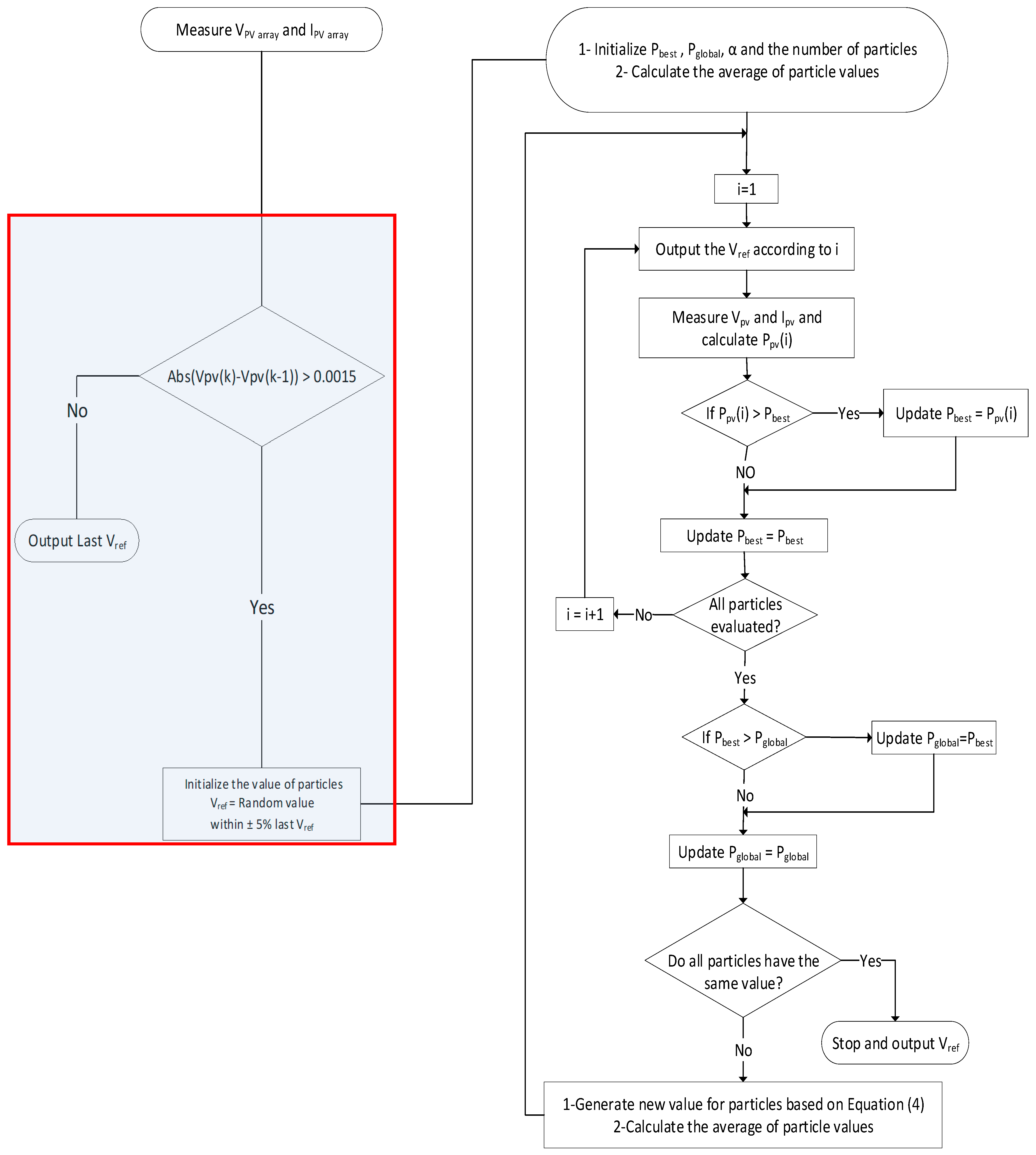
3.1. The Modified GMPP BES-Based Method Overview

According to [34], the use of the first stage of the BES searching technique is appropriate for locating the global maximum power point for the PV system operating under partial shading conditions, as the finding of the maximum power point in the P-V curve of the PV system is similar to solving a simple one-dimension optimization problem. This study modified the BES-GMPP searching method in [34] such that it would also function as the MPPT. For context, the main task of the original algorithm of the BES-GMPP is to locate the GMPP of the PV system experiencing PSC.
The new algorithm was developed by adding one more condition to the original algorithm of BES-GMPP. This modification was used for detecting minor variations in the insolation and ambient temperature by sensing the change in the output voltage of the PV array. Once the added condition was met, the study suggested feeding the initial step of the searching process with a new set of initial values of particles. These new initial values of particles are distributed within ± 5 % (narrow range) of the last reference voltage, unlike the original algorithm, which assigned the initial values within the minimum and maximum voltages (wide range). The reason for setting a very narrow range for the particles used for finding the MPP value is that this study saw that the best voltage reference to operate the PV system at the right MPP value must be very close to the last voltage reference as the change in the insolation or ambient temperature is very small. The new modifications to the GMPP algorithm are highlighted in blue in Figure 1.
After the modifications made in the GMPP BES-based method, the algorithm could continuously monitors the changes in the PV array’s voltage, current, and power to determine whether the system was experiencing a universal change in insolation and ambient temperature. The algorithm fed the right initial values of particles to the GMPP search process steps upon the added condition being met. After feeding the appropriate initial values of particles, according to Equation (4), the average value of the particles was calculated before calculating the new values of the particles. Following that, each particle (in this case, the PV reference voltages, i.e., Vi (i = 1, 2, … n)) value was pushed to the PV system to sense the output voltage and compute the output power. The maximum output power was found when all particle values had been pushed to the PV system, and this was stored as a global power and the best power. Following that, a new set of particle values was generated using Equation (4). Afterward, the new particle values were pushed to a PV system, where their corresponding powers were calculated. When this process was complete, the highest output power would be stored as the best new power. The best new power output was chosen as the global power if it was higher than that stored in the global power. The method replicated this process until all particles were given the same value, which the PV system ran at the global MPP.
V i = V best + α × r V mean V i  

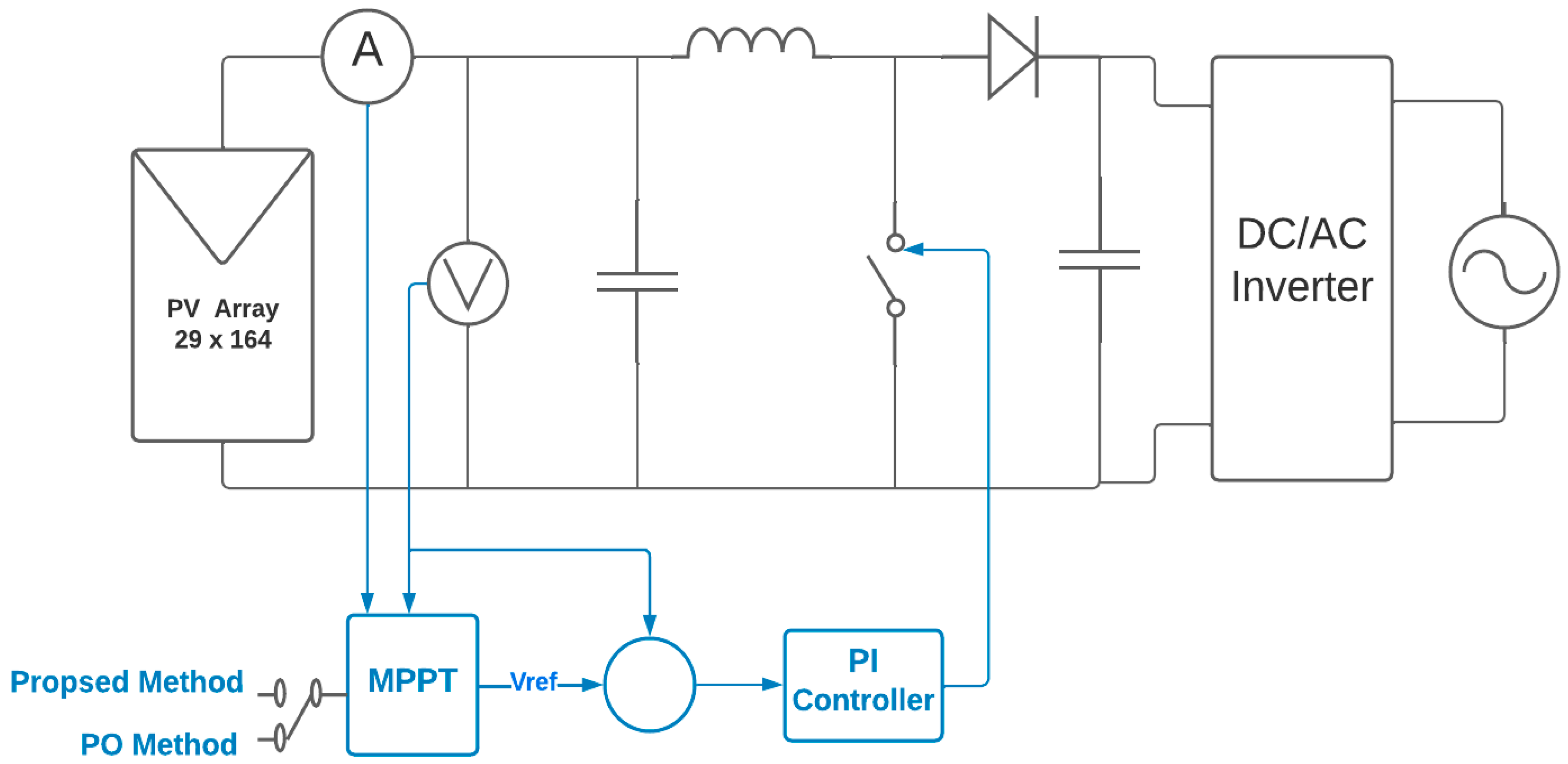
3.2. Description of the Grid-Connected PV System

To test the effectiveness and performance of the proposed method, a model of a grid-connected PV system was developed in an RTDS (real-time digital simulator) experimental device. The RTDS simulator, produced by RTDS Technologies, is the world’s leading provider of real-time digital power system simulation. The simulator is equipped with specially designed hardware and software (RSCAD), as shown in Figure 2, which were specifically designed to simulate real-time electromagnetic transients (EMTs). The simulator is continuously operated in real time while providing accurate results over a wide frequency range. Moreover, the RTDS simulator was designed to simulate complex networks using a typical time step of 25–50 s, thanks to its fully digital parallel processing hardware. With the simulator, it is also possible to simulate power electronics devices with switching frequencies as high as 150 kHz using smaller timesteps [35].
The single-diode and five-parameter models were used in this study to model the PV cell, which is represented as a current source with a paralleled diode. A common practical model would extend the PV cell by including a series and a shunt resistor. The current–voltage relationship between the single-diode and solar cell models is provided by [36]:
I = I p h I D I s h = I p h I o e V + R s V t a 1 V + R s R s h   ,
where I o is the diode reverse saturation current, a is called the diode ideality factor and is a measure of how closely the diode matches the ideal diode equation, I p h is photocurrent of the solar cell, I D is the diode current, R s is the sum of several structural resistances in the solar cell, and R s h is to model the leakage current of the semiconductor material.
The PV model component requires the below parameters to model a solar cell. The nominal (standard) test conditions refer to the standard temperature T r e f = 25 °C and the standard solar intensity G r e f = 1000 W/m2. We note that the below parameters were set for a string of N c series-connected solar cells:
  • V o c r e f : open circuit voltage;
  • I s c r e f : short circuit current;
  • V m p r e f : voltage at the maximum power point;
  • I m p r e f : current at the maximum power point;
  • k i : short circuit current–temperature coefficient in %/°C;
  • k v : open circuit voltage–temperature coefficient in %/°C;
  • R o s : open circuit series resistor;
  • R s h o : short circuit resistance;
  • E g : energy gap of the selected solar cell semiconductor material.
I p h = G G r e f I p h r e f 1 + K i T T r e f   I o = I o r e f T T r e f e x p E g a r e f k T q T T r e f 1  
a r e f = V m p r e f + I m p r e f R s o V o c r e f N c V r e f ln I s c r e f V m p r e f R s h o I m p r e f ln I s c r e f V o c r e f R s h o + I m p r e f I s c r e f V o c r e f R s h o I o r e f = I o r e f T T r e f e x p V o c r e f a r e f V t r e f R s h r e f = R s h o R s r e f = R s o a r e f V t r e f I o r e f e x p V o c r e f a r e f V t r e f I p h r e f = I s c r e f 1 + R r e f R s h r e f + I o r e f   e x p I s c r e f   R s r e f a r e f V t r e f 1
R s _ t o t = N s N p N c p R s ,   R s = R s r e f G r e f G R s h _ t o t = N s N p N c p R s h ,   R s h = R s h r e f G r e f G  
In the above equations, V t is the diode thermal voltage, which is a constant defined at any given temperature T (in K) by [36]:
V t = k T q  
V t r e f is the diode terminal voltage at the temperature T r e f and is calculated as follows:
V t r e f = k T r e f q   ,
where k is the Boltzmann constant (1.3806503 × 10⁻²³ J/K) and q is the magnitude of an electron charge (1.602176 × 10⁻¹⁹ C).
For most PV products, manufacturers may provide a minimum unit with a number of series-connected solar cells. Customers may use a number of solar cell strings in parallel to form a PV module and use a number of such PV modules in series, in parallel, or both, to form a PV array. The relevant parameters of the solar cell arrangement are defined as follows:
N c : number of series-connected cells per string per module;
N c p : number of parallel strings of cells per module;
N s : number of modules in series to form the PV array;
N p : number of modules in parallel to form the PV array.
With the above-defined parameters for a PV array arrangement, the current–voltage curve for the formed PV array, under a general temperature T and solar intensity G, are expressed below:
V o c r e f _ P V = N s V o c r e f ,   I s c r e f _ P V = N c p N p I s c r e f V m p r e f _ P V = N s V m p r e f ,   I m p r e f _ P V = N c p N p I m p r e f P m p r e f _ P V = V m p r e f _ P V I m p r e f _ P V = N s N c p N p V m p r e f I m p r e f   .
By using RSCAD, the PV system model illustrated in Figure 3 is used and linked with RTDS hardware to calculate the output power and voltage of the PV array as a function of changes in the insolation. In this model, a 1 MW PV array of 29 ∗ 164 PV modules was connected in a series-parallel configuration, with DC-DC boost converter and an inverter. The inverter was controlled by using a current-mode controller composed of two control loops—an outer control loop and an inner control loop. The controller was designed in the dq-frame. The d-axis component of the outer-loop control regulated the inverter dc capacitor voltage or the dc power, and the q-axis component of the outer-loop control regulated the inverter system’s ac side reactive power or the ac bus voltage. Table 1 lists the parameters of the PV array, boost converter, and inverter.

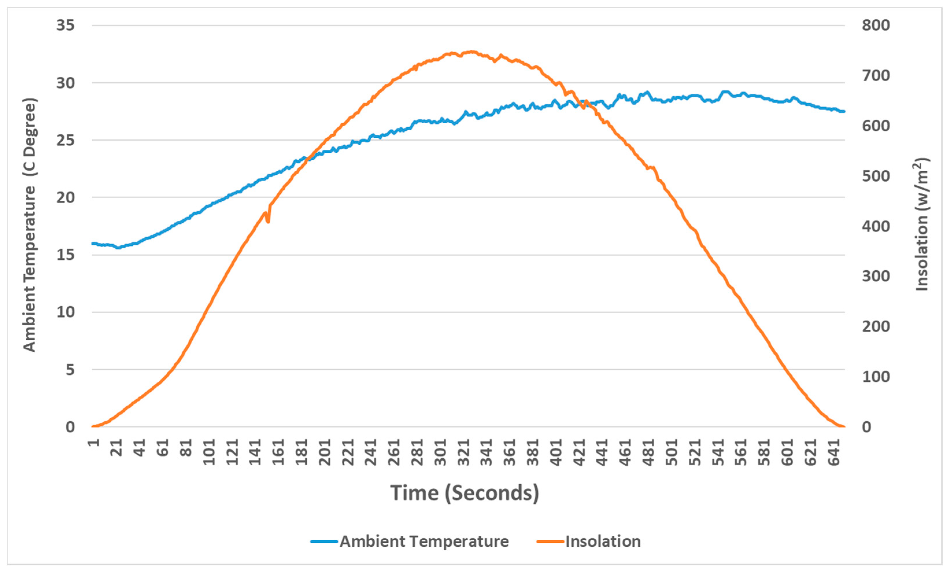
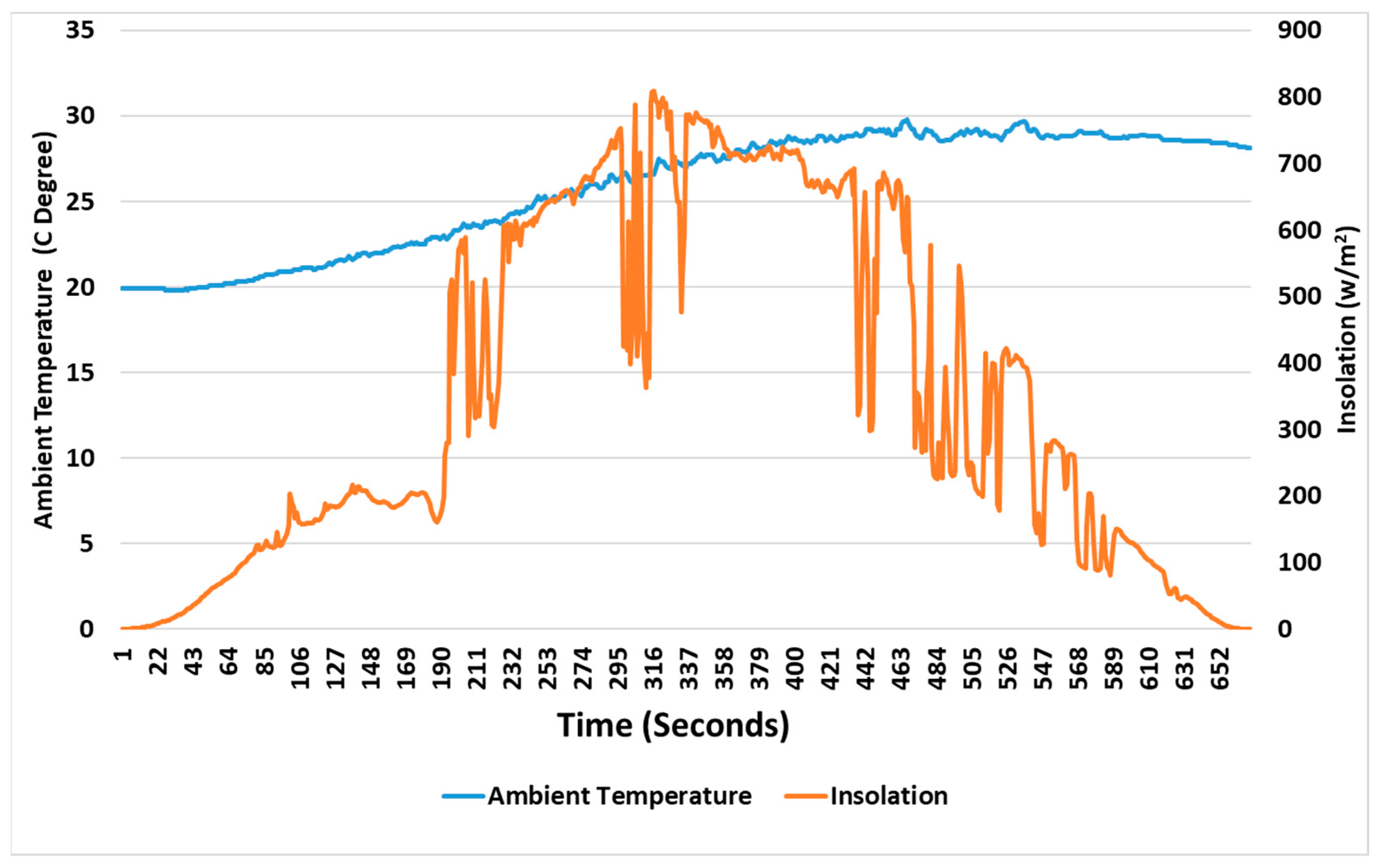
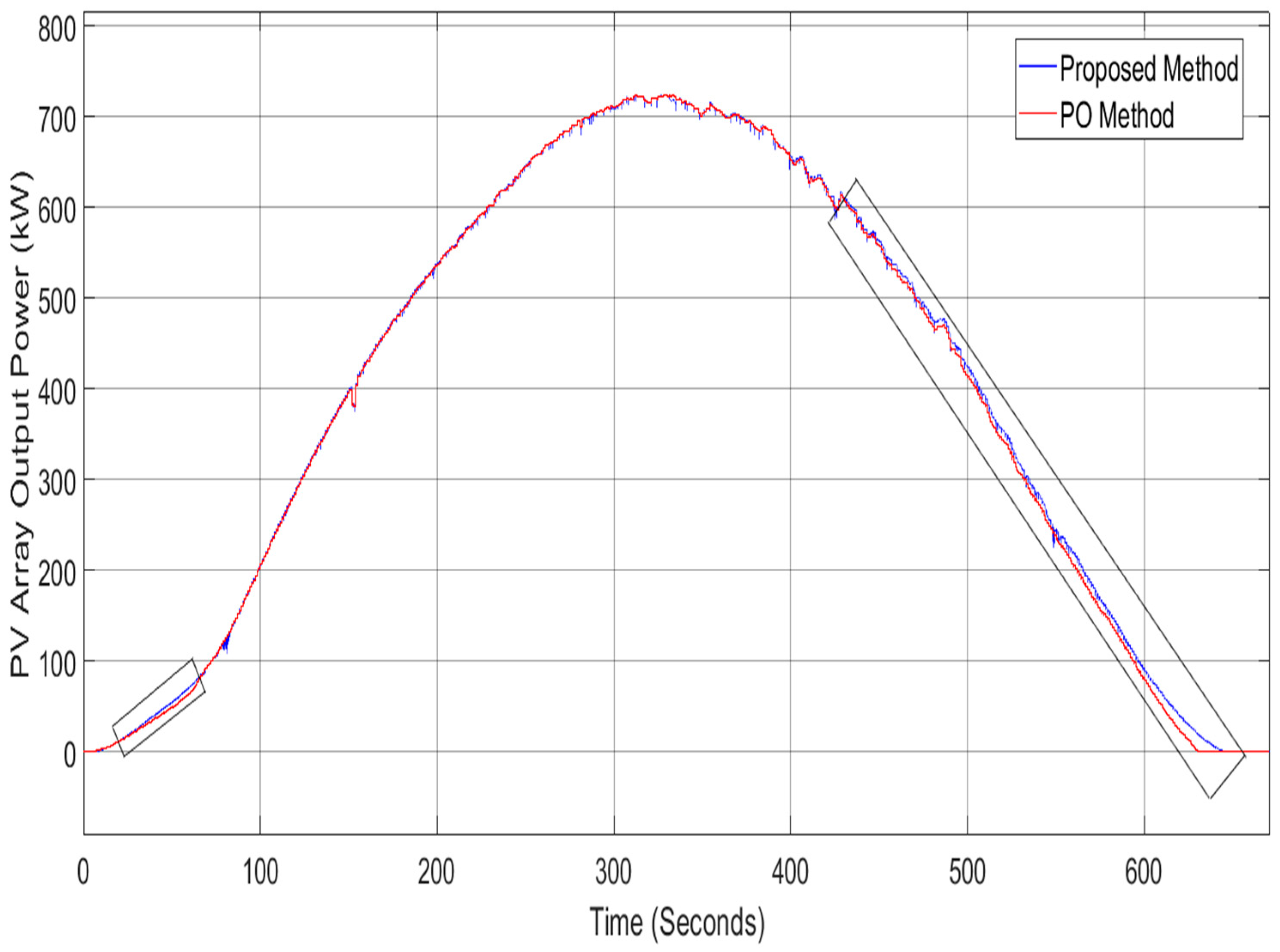
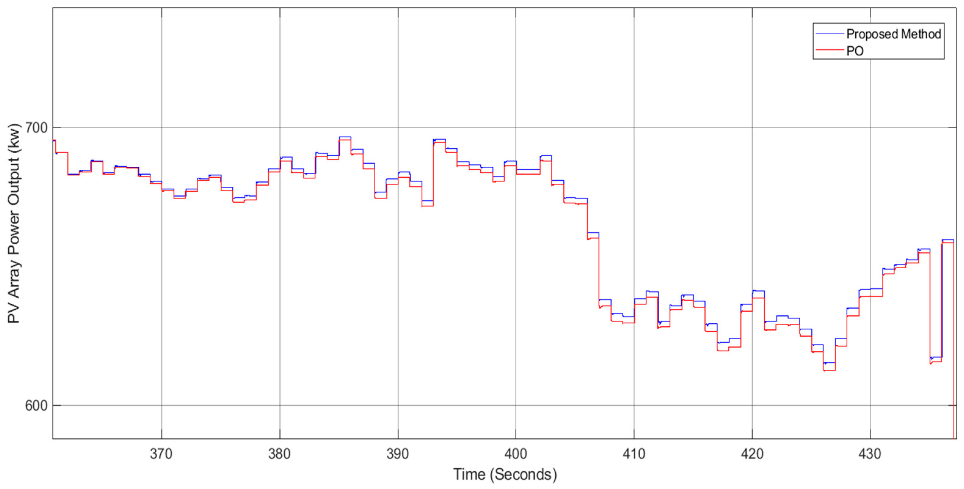
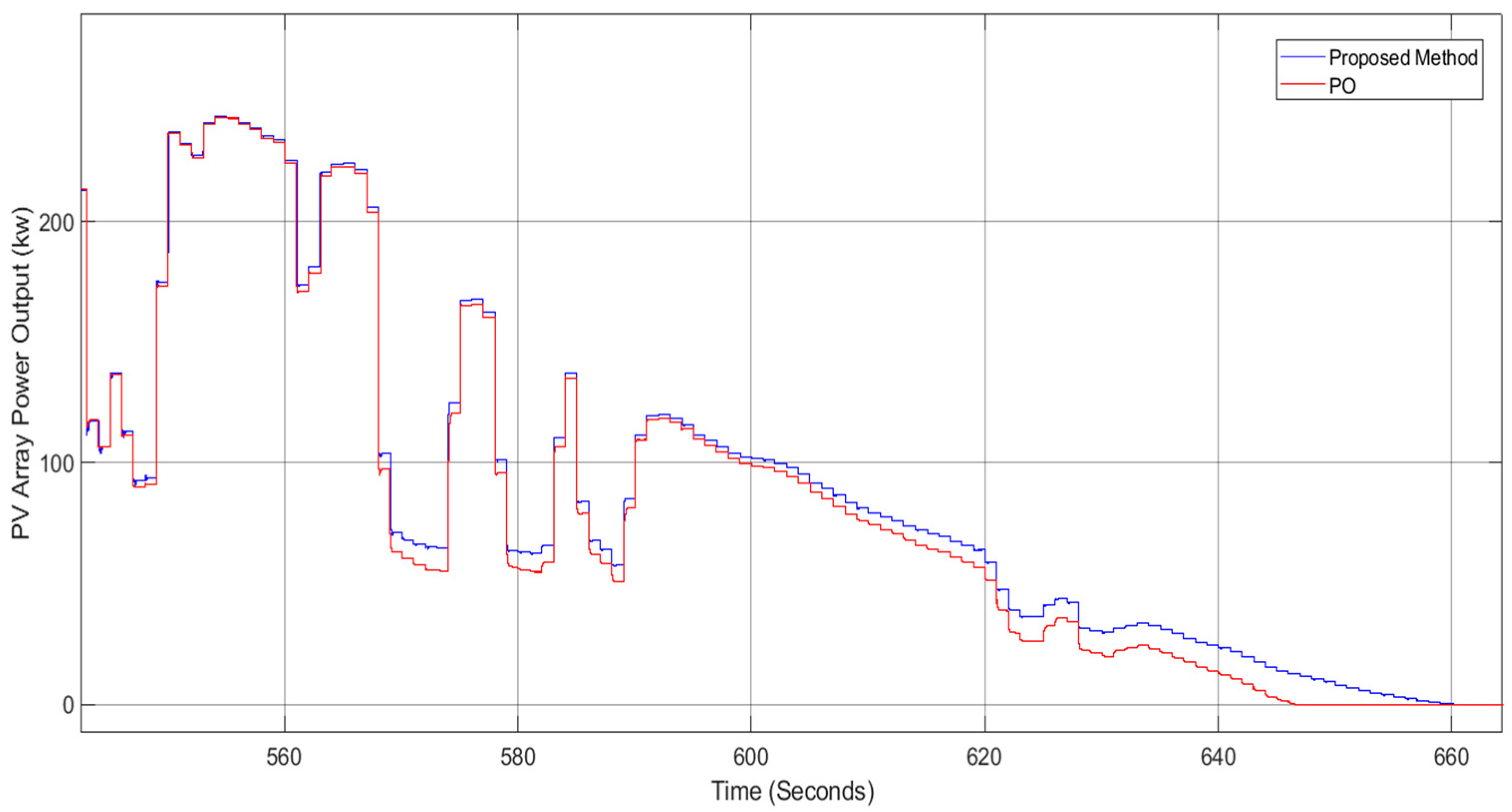
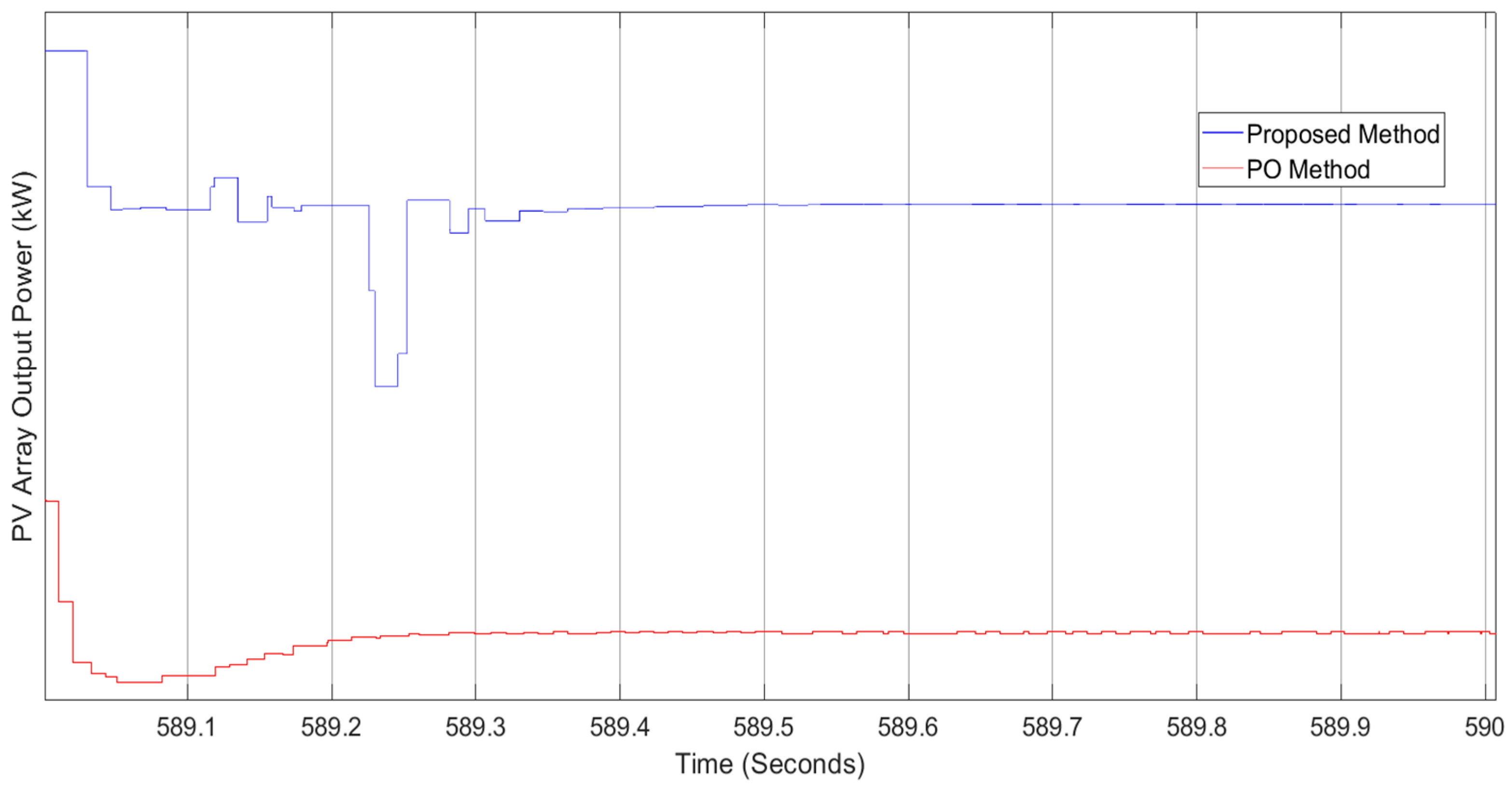
3.3. Results and Discussion

This study investigated the performance of the proposed MPPT BES based on a comparison with one popular MPPT method. The PO method was chosen as the benchmark because of its excellent performance reported in [10]. Real data of the insolation and ambient temperature (illustrated in Figure 4 and Figure 5) for clear and cloudy days were used to test the effectiveness and performance of the proposed modified GMPP BES-based method and the PO method. Table 2 presents the parameters used and the MPPT voltage range in both methods.
A look at the output power waveforms in Figure 6 demonstrates that the modified method produces the correct MPP values better than the PO method. The same is clearly illustrated in Figure 6, which shows that the proposed method outputs more power than the PO method during the periods indicated by rectangles. As a result, this method correctly detects changes in insolation and temperature and determines the correct MPPT value quickly.
In addition, the proposed method gained an approximate amount of energy (5242.92 kwh), which was more than that of the PO method (5192.67 kwh) by approximately 50.25 kwh at the end of a clear day, as shown in Figure 7. Assuming that the weather is clear every day of the year, the proposed method gains 18.341 MWh over the PO method. Hence, this algorithm may prove to be a viable option for large-scale PV farms where harvested energy is of critical importance.
Tracking the MPP of a PV system during cloudy weather is the most challenging assessment for the MPPT methods. The proposed method, as shown in Figure 8, was successful in maintaining the PV system’s performance at MPP throughout a cloudy day, even when the insolation values fluctuated significantly. According to the circled portions in Figure 8, Figure 9 and Figure 10, where the insolation dropped and increased dramatically, the proposed method produced a better performance result than the PO method since it operates the PV system at a higher MPP value than the PO method.
In this sense, it can be said that the proposed method performs better than the PO method both in terms of its ability to respond to changes in insolation and ambient temperature and its ability to arrive at/track the correct MPP values during clear and cloudy days. The proposed method gained more energy than the PO method (by approximately 1%). Moreover, it is important to note that the proposed method only adjusted the operating voltage of the PV system concerning the insolation and temperature changes, whereas the PO MPPT method continuously adjusted the operating voltage. As a result of this feature, the proposed method produced nearly zero oscillation at the maximum power point and prevented the power loss and waste that result from oscillations at the MPP, as can be seen in Figure 11. With respect to tracking speed, the proposed method and the PO method reached the MPP at approximately the same time, i.e., 0.33 s and 0.328 m seconds, respectively, as shown in Figure 12.

4. Conclusions

As renewable energy becomes more prevalent, it is also becoming more critical for achieving sustainable development, energy security, and reductions in greenhouse gases. In most parts of the world, solar PV systems are becoming the lowest-cost option for generating electricity, which is expected to boost investment. MPPT methods play a significant role in improving the efficiency of PV systems as they ensure PV systems can generate their maximum power at any point in time under ambient temperatures or insolation changes. However, these MPPT methods do not guarantee that the PV system will operate at its maximum capacity during clear, cloudy, or partial shading conditions. Hence, in this paper, we have proposed a modification to the GMPP BES-based method that tracks the MPP under uniform irradiation, as well as under partial shading conditions, and we tested it on a grid-connected PV system. The GMPP BES-based method was found to be a good method for locating the GMPP under different PSCs due to its many advantages, including its fast convergence and simplicity. As it does not work as a MPP tracker under normal operations (i.e., no PSC occurrences), modifications were made in this study to enable the GMPP BES method to detect minor changes in insolation and temperature by monitoring the variation in the output voltage of the PV array and then triggering the searching process to find a suitable MPP voltage. The modified method was evaluated using a real-time digital simulator (RTDS) with real data changes in insolation and ambient temperatures under clear and cloudy conditions. Based on the RTDS results, the modified method and the PO method arrived at the MPP value at nearly at the same time. However, the proposed method was able to locate the MPP values with high accuracy. and it gained more energy (5242.92 kwh) than the PO method (5192.67 kwh) by approximately 1%. In addition, the results demonstrate that the proposed method performed better than the PO method in terms of providing the correct MPP values under significant/sudden changes in insolation fluctuations. Therefore, with these advantages of the proposed method, it can be said that the proposed method is a practical solution for solar farms that need to harvest substantial amounts of energy.

Author Contributions

Conceptualization, W.A.A.; methodology, W.A.A.; software, W.A.A. and A.A.-H.; validation, W.A.A., R.A.A. and H.Y.; resources, A.A.-H.; data curation, W.A.A.; writing—original draft, W.A.A.; writing—review and editing, R.A.A., H.Y. and A.A.-H.; supervision, R.A.A., H.Y. and A.A.-H. All authors have read and agreed to the published version of the manuscript.

Funding

This research received no external funding.

Acknowledgments

The authors acknowledge Sultan Qaboos University, Sustainable Energy Research Center, and Occidental Oman for their support. Without the facilities and equipment provided by these contributors, the results would not have been possible.

Conflicts of Interest

The authors declare no conflict of interest.

Abbreviations

The following abbreviations are used in this manuscript:
PSOparticle swarm optimization
CScuckoo search
ICincremental conductance
GWOgrey wolf optimization
FAfirefly algorithm
GAgenetic algorithm
BAbat algorithm
ACOant colony optimization
BESbald eagle search
PSCpartial shading condition(s)
GMPPglobal maximum power peak
MPPmaximum power peak
FLCfuzzy logic control
HSFLAhybrid shuffled frog-leaping
PSpattern search
ANFISadaptive neuro-fuzzy inference system
PIproportional integral
NAGNesterov accelerated gradient
THDtotal harmonic distortion

References

  1. IEA. Solar PV; IEA: Paris, France, 2022; Available online: https://www.iea.org/reports/solar-pv (accessed on 28 November 2022).
  2. Al Hatmi, Y.; Tan, C. Issues and challenges with renewable energy in Oman. Gas 2013, 4, 212–218. [Google Scholar]
  3. Hafeez, M.A.; Naeem, A.; Akram, M.; Javed, M.Y.; Asghar, A.B.; Wang, Y. A Novel Hybrid MPPT Technique Based on Harris Hawk Optimization (HHO) and Perturb and Observer (P&O) under Partial and Complex Partial Shading Conditions. Energies 2022, 15, 5550. [Google Scholar]
  4. da Luz, C.M.A.; Vicente, E.M.; Tofoli, F.L. Experimental evaluation of global maximum power point techniques under partial shading conditions. Sol. Energy 2020, 196, 49–73. [Google Scholar] [CrossRef]
  5. Spertino, F.; Ahmad, J.; Ciocia, A.; Di Leo, P.; Murtaza, A.F.; Chiaberge, M. Capacitor charging method for I–V curve tracer and MPPT in photovoltaic systems. Sol. Energy 2015, 119, 461–473. [Google Scholar] [CrossRef] [Green Version]
  6. Sarvi, M.; Ahmadi, S.; Abdi, S. A PSO-based maximum power point tracking for photovoltaic systems under environmental and partially shaded conditions. Prog. Photovolt. Res. Appl. 2015, 23, 201–214. [Google Scholar] [CrossRef]
  7. Subudhi, B.; Pradhan, R. A comparative study on maximum power point tracking techniques for photovoltaic power systems. IEEE Trans. Sustain. Energy 2012, 4, 89–98. [Google Scholar] [CrossRef]
  8. Hsieh, G.; Hsieh, H.; Tsai, C.; Wang, C. Photovoltaic Power-Increment-Aided Incremental-Conductance MPPT with Two-Phased Tracking. IEEE Trans. Power Electron. 2013, 28, 2895–2911. [Google Scholar] [CrossRef]
  9. Motahhir, S.; El Ghzizal, A.; Sebti, S.; Derouich, A. Modeling of Photovoltaic System with Modified Incremental Conductance Algorithm for Fast Changes of Irradiance. Int. J. Photoenergy 2018, 2018, 3286479. [Google Scholar] [CrossRef] [Green Version]
  10. Alik, R.; Jusoh, A. An enhanced P&O checking algorithm MPPT for high tracking efficiency of partially shaded PV module. Sol. Energy 2018, 163, 570–580. [Google Scholar] [CrossRef]
  11. Devarakonda, A.K.; Karuppiah, N.; Selvaraj, T.; Balachandran, P.K.; Shanmugasundaram, R.; Senjyu, T. A Comparative Analysis of Maximum Power Point Techniques for Solar Photovoltaic Systems. Energies 2022, 15, 8776. [Google Scholar] [CrossRef]
  12. Seyedmahmoudian, M.; Rahmani, R.; Mekhilef, S.; Oo, A.M.T.; Stojcevski, A.; Soon, T.K.; Ghandhari, A.S. Simulation and Hardware Implementation of New Maximum Power Point Tracking Technique for Partially Shaded PV System Using Hybrid DEPSO Method. IEEE Trans. Sustain. Energy 2015, 6, 850–862. [Google Scholar] [CrossRef]
  13. Titri, S.; Larbes, C.; Toumi, K.Y.; Benatchba, K. A new MPPT controller based on the Ant colony optimization algorithm for Photovoltaic systems under partial shading conditions. Appl. Soft Comput. 2017, 58, 465–479. [Google Scholar] [CrossRef]
  14. Ahmed, J.; Salam, Z. A Maximum Power Point Tracking (MPPT) for PV system using Cuckoo Search with partial shading capability. Appl. Energy 2014, 119, 118–130. [Google Scholar] [CrossRef]
  15. Nugraha, D.A.; Lian, K.; Suwarno. A Novel MPPT Method Based on Cuckoo Search Algorithm and Golden Section Search Algorithm for Partially Shaded PV System. In Proceedings of the 2018 IEEE Electrical Power and Energy Conference (EPEC), Toronto, ON, Canada, 10–11 October 2018; pp. 1–6. [Google Scholar]
  16. Mohanty, S.; Subudhi, B.; Ray, P.K. A New MPPT Design Using Grey Wolf Optimization Technique for Photovoltaic System Under Partial Shading Conditions. IEEE Trans. Sustain. Energy 2016, 7, 181–188. [Google Scholar] [CrossRef]
  17. Teshome, D.F.; Lee, C.H.; Lin, Y.W.; Lian, K.L. A Modified Firefly Algorithm for Photovoltaic Maximum Power Point Tracking Control Under Partial Shading. IEEE J. Emerg. Sel. Top. Power Electron. 2017, 5, 661–671. [Google Scholar] [CrossRef]
  18. Ramaprabha, R.; Mathur, B. Genetic algorithm based maximum power point tracking for partially shaded solar photovoltaic array. Int. J. Res. Rev. Inf. Sci. (IJRRIS) 2012, 2. [Google Scholar]
  19. Mohajeri, H.R.; Moghaddam, M.P.; Shahparasti, M.; Mohamadian, M. Development a new algorithm for maximum power point tracking of partially shaded photovoltaic arrays. In Proceedings of the 20th Iranian Conference on Electrical Engineering (ICEE2012), Tehran, Iran, 15–17 May 2012; pp. 489–494. [Google Scholar]
  20. Kaced, K.; Larbes, C.; Ramzan, N.; Bounabi, M.; elabadine Dahmane, Z. Bat algorithm based maximum power point tracking for photovoltaic system under partial shading conditions. Sol. Energy 2017, 158, 490–503. [Google Scholar] [CrossRef] [Green Version]
  21. Pervez, I.; Pervez, A.; Tariq, M.; Sarwar, A.; Chakrabortty, R.K.; Ryan, M.J. Rapid and Robust Adaptive Jaya (Ajaya) based Maximum Power Point Tracking of a PV-based Generation System. IEEE Access 2020, 9, 48679–48703. [Google Scholar] [CrossRef]
  22. Pervez, I.; Shams, I.; Mekhilef, S.; Sarwar, A.; Tariq, M.; Alamri, B. Most Valuable Player Algorithm Based Maximum Power Point Tracking for a Partially Shaded PV Generation System. IEEE Trans. Sustain. Energy 2021, 12, 1876–1890. [Google Scholar] [CrossRef]
  23. Bjaoui, M.; Khiari, B.; Benadli, R.; Memni, M.; Sellami, A. Practical implementation of the backstepping sliding mode controller MPPT for a PV-storage application. Energies 2019, 12, 3539. [Google Scholar] [CrossRef] [Green Version]
  24. Vázquez, N.; Azaf, Y.; Cervantes, I.; Vázquez, E.; Hernández, C. Maximum power point tracking based on sliding mode control. Int. J. Photoenergy 2015, 2015, 380684. [Google Scholar] [CrossRef]
  25. Guo, S.; Abbassi, R.; Jerbi, H.; Rezvani, A.; Suzuki, K. Efficient maximum power point tracking for a photovoltaic using hybrid shuffled frog-leaping and pattern search algorithm under changing environmental conditions. J. Clean. Prod. 2021, 297, 126573. [Google Scholar] [CrossRef]
  26. Hamidi, F.; Olteanu, S.C.; Popescu, D.; Jerbi, H.; Dincă, I.; Ben Aoun, S.; Abbassi, R. Model Based Optimisation Algorithm for Maximum Power Point Tracking in Photovoltaic Panels. Energies 2020, 13, 4798. [Google Scholar] [CrossRef]
  27. Hassan, T.-U.; Abbassi, R.; Jerbi, H.; Mehmood, K.; Tahir, M.F.; Cheema, K.M.; Elavarasan, R.M.; Ali, F.; Khan, I.A. A novel algorithm for MPPT of an isolated PV system using push pull converter with fuzzy logic controller. Energies 2020, 13, 4007. [Google Scholar] [CrossRef]
  28. Latifi, M.; Abbassi, R.; Jerbi, H.; Ohshima, K. Improved krill herd algorithm based sliding mode MPPT controller for variable step size P&O method in PV system under simultaneous change of irradiance and temperature. J. Frankl. Inst. 2021, 358, 3491–3511. [Google Scholar]
  29. Mohammadinodoushan, M.; Abbassi, R.; Jerbi, H.; Ahmed, F.W.; Rezvani, A. A new MPPT design using variable step size perturb and observe method for PV system under partially shaded conditions by modified shuffled frog leaping algorithm-SMC controller. Sustain. Energy Technol. Assess. 2021, 45, 101056. [Google Scholar] [CrossRef]
  30. Li, G.; Jin, Y.; Akram, M.; Chen, X.; Ji, J. Application of bio-inspired algorithms in maximum power point tracking for PV systems under partial shading conditions–A review. Renew. Sustain. Energy Rev. 2018, 81, 840–873. [Google Scholar] [CrossRef]
  31. Belhachat, F.; Larbes, C. A review of global maximum power point tracking techniques of photovoltaic system under partial shading conditions. Renew. Sustain. Energy Rev. 2018, 92, 513–553. [Google Scholar] [CrossRef]
  32. Liu, Y.-H.; Chen, J.-H.; Huang, J.-W. A review of maximum power point tracking techniques for use in partially shaded conditions. Renew. Sustain. Energy Rev. 2015, 41, 436–453. [Google Scholar] [CrossRef]
  33. Alsattar, H.A.; Zaidan, A.A.; Zaidan, B.B. Novel meta-heuristic bald eagle search optimisation algorithm. Artif. Intell. Rev. 2020, 53, 2237–2264. [Google Scholar] [CrossRef]
  34. Abri, W.A.; Abri, R.A.; Yousef, H.; Al-Hinai, A. A Global MPPT Based on Bald Eagle Search Technique for PV System Operating under Partial Shading Conditions. In Proceedings of the 2022 10th International Conference on Smart Grid (icSmartGrid), Istanbul, Turkey, 27–29 June 2022; pp. 325–332. [Google Scholar]
  35. RTDS Technologies Inc. Available online: https://www.rtds.com (accessed on 20 October 2022).
  36. Singh, S.; Mathew, L.; Shimi, S. Design and simulation of intelligent control MPPT technique for PV module using MATLAB/SIMSCAPE. Int. J. Adv. Res. Electr. Electron. Instrum. Eng. 2013, 2, 4554–4566. [Google Scholar]
Figure 1. Flow diagram of the proposed MPP tracking method based on the BES technique.
Energies 15 09185 g001
Figure 2. Hardware and software components of the RTDS.
Energies 15 09185 g002
Figure 3. Schematic of the modeled grid-connected PV system in RTDS.
Energies 15 09185 g003
Figure 4. Curves of the actual insolation and ambient temperature for a clear day.
Energies 15 09185 g004
Figure 5. Curves of the actual insolation and ambient temperature for a cloudy day.
Energies 15 09185 g005
Figure 6. Output power of the proposed method and the PO method on a clear day.
Energies 15 09185 g006
Figure 7. Total energy of the proposed method and the PO method for a clear day.
Energies 15 09185 g007
Figure 8. Output power of the proposed method and the PO method on a cloudy day.
Energies 15 09185 g008
Figure 9. Sample of the output power of the proposed method and the PO method for a period (370–430) of time on a cloudy day.
Energies 15 09185 g009
Figure 10. Sample of the output power of the proposed method and the PO method for a period (560–660) of time on a cloudy day.
Energies 15 09185 g010
Figure 11. Sample of the output power of the proposed method and the PO method for a period (589–590) of time on a clear day.
Energies 15 09185 g011
Figure 12. Sample of the output power of the proposed method and the PO method for a period (568–568.55) of time on a cloudy day.
Energies 15 09185 g012
Table 1. Grid-connected PV system specifications.
PV System Specification
PV ArrayDC/AC InverterDC-DC Boost Converter
ParameterValueParameterValueParameterValue
Number of PV modules in a series-parallel configuration 4.756Rated input voltage0.8 kVRated output voltage 0.8 kV
Open circuit voltage of the PV array at a standard testing condition (STC) 0.63 kVSwitching frequency2 kHzSwitching frequency2 kHz
Short circuit current of the PV array at the STC 2.197 k ALFilter1.6 × 10−-4 HRated input current2.2 kA
Voltage at the Pm at the STC 0.495 kVCFilter500 µFLin0.001525 H
Current at the Pm at the STC 2 kADC Bus capacitor32,000 µFCin and Cout350 µF and 250 µF
Maximum power at the STC 1000 kW PI controller parameters Kp and Ti0.5 and 0.05
Table 2. Parameters of the PO-MPPT and the proposed BES-MPPT.
MethodParametersMPPT Voltage Range
PO-MPPT V = 0.5250 V–495 V
Proposed GMPP BES-based-MPPTα = 0.1
Number of particles = 10
250 V–495 V
Publisher’s Note: MDPI stays neutral with regard to jurisdictional claims in published maps and institutional affiliations.

