Article

Coupling Microbial Fuel Cell and Hydroponic System for Electricity Generation, Organic Removal, and Nutrient Recovery via Plant Production from Wastewater

Department of Civil and Environmental Engineering, Idaho State University, 921 S. 8th Ave., Stop 8060, Pocatello, ID 83209, USA
*
Author to whom correspondence should be addressed.
Energies 2022, 15(23), 9211; https://doi.org/10.3390/en15239211
Submission received: 7 November 2022 / Revised: 25 November 2022 / Accepted: 2 December 2022 / Published: 5 December 2022
(This article belongs to the Special Issue Microbial Fuel Cells II)

Abstract

:
The world is predicted to face serious threats from the depletion of non-renewable energy resources, freshwater shortage, and food scarcity. Microbial fuel cells (MFCs) are innovative bio-electrochemical devices capable of directly converting chemical energy into electrical energy using microorganisms as a catalyst. This ability has been explored for generating electricity using wastewater as an energy source, while simultaneously treating wastewater. On the other hand, hydroponics is the cultivation of plants in water without soil. The goal of this study was to develop a novel integrated microbial fuel cell-hydroponic system (MFC-Hyp system) that possesses the ability to concurrently generate electricity while degrading organic pollutants (Chemical oxygen demand, COD) in wastewater, remove and recover nutrients (phosphorus, P and nitrogen, N) from the wastewater, and produce edible plants. The MFC-Hyp system developed in this study produced a power density of 250.7 mW/m2. The power density increased by approximately 19% and the phosphorus recovery increased to 7.5% in the presence of Allium tuberosum compared to 4.9% without the plant (e.g., in the control). The removal efficiencies of nitrate, phosphate, and COD are 32%, 11%, and 80%, respectively. The results indicate that the novel integrated MFC-Hyp system can remove COD from wastewater, generate electricity using wastewater as an energy source, and utilize nutrients for growing plants; however, this system requires further improvement for field implementation.

1. Introduction

Water, energy, and food are essential for all living forms to survive and thrive, and they are inseparably linked. Although humans have made great strides in securing those resources, the world is facing an uphill battle due largely to the increasing human population and climate change. By the next decade, the world is expected to face a 40% fresh water and 36% energy shortage [1,2], along with increasing demand for food [3,4] and treatment of wastewater.
The discharge of wastewater containing high levels of organics and nutrients to a receiving water body is a potential cause of eutrophication and hypoxia in the water environment [5,6]. On the other hand, phosphorus is essential to all forms of life and crucial to crop yields [7], and there is no substitute for it [8]. As the world population is projected to grow to 9 billion by 2050, securing a phosphorus supply is critical to future food security [7].
Currently, about half of the food production in the world is dependent on synthetic fertilizers [9]. Wastewater treatment plants (WWTPs) are unexploited sources of phosphorus with an annual worldwide potential of 3 million tons of phosphate [10,11]. It is estimated that the total phosphorus available in sewage if recovered fully, could supply about 15–20% of the global phosphorus demand [12], which can be an imaginable substitute for phosphate rock mines. Nitrogen used in producing fertilizer is predominantly manufactured using the industrial Haber-Bosch process [8]. The Haber-Bosch process is an energy-intensive process that requires high temperature and pressure. In recent years, wastewater has been considered a renewable resource of water [13], nutrients, and energy [13,14,15,16]. Since phosphorus and nitrogen are the principal ingredients of fertilizer, the recovery of phosphorus (P) and nitrogen (N) (such as by plants) from wastewater is now becoming recognized as a rational approach [17].
Currently, most conventional WWTPs are energy-consuming facilities that employ energy-intensive strategies such as aeration-based heterotrophic biological treatment [18,19]. According to the Electric Power Research Institute [20], up to 3–4% of the total electricity consumed in the U.S. is related to the water management cycle, including wastewater treatment [21]. In comparison with the energy-intensive wastewater treatment methods currently employed in the conventional WWTPs, microbial fuel cells (MFCs) have the advantage that they can generate electricity with the potential ability to separate nutrients from wastewater. If the energy contained in wastewater were effectively recovered, no external energy input would be required to operate WWTPs [8,22].
Microbial fuel cells (MFCs) are bioelectrochemical systems capable of using wastewater as an energy source to generate electricity while treating wastewater. MFCs have attracted considerable attention due to their versatility in their applications in wastewater treatment, power generation, environmental sensors, nutrient recovery, and many more [5,18,23,24,25,26,27]. In principle, a single chamber MFC consists of an anode, cathode, microorganisms, substrate (anolyte), and conductive wire (external circuit). MFCs are eco-friendly biotechnologies in which electrogenic or electroactive bacteria (EAB) convert chemical energy contained in substrates to electricity [8,28,29]. The EAB acts as a biocatalyst for the oxidation of the substrate and transferring electrons to the anode [27,30]. Domestic, agricultural, and industrial wastewaters contain various substrates that can serve as renewable fuel sources for MFCs [23,31]. Since MFCs can capture a large fraction of chemical energy contained in wastewater [8,28], they have the potential to be self-sustaining wastewater treatment technologies that require no external power sources and to provide sustainable wastewater treatment with a low carbon footprint [32].
Hydroponics is the process of growing plants in water without soil. In a hydroponic system, nutrients in water and carbon dioxide in the air can be captured and stored as biomass in plants, while oxygen is produced via photosynthesis. Thus, hydroponic systems are considered an environmentally friendly technology that can be applied to wastewater reuse, while improving water quality [25,33]. The goal of this research was to develop a novel sustainable energy generation-resource recovery system by coupling an MFC with hydroponics (Hyp). By integrating the two, the new system is expected to outperform the individual processes in terms of increased net energy output, enhanced utilization of CO2 and nutrients (phosphorus, P and nitrogen, N), and consequently improve environmental quality. The specific objectives were to design, construct, run, monitor, and evaluate the novel laboratory-scale MFC-Hyp technology. Therefore, a novel integrated MFC-Hyp system is expected to provide multiple functions including nutrient recovery, food production, and water purification, in addition to the MFC’s functions (i.e., wastewater treatment, and electricity generation).

2. Methodology

2.1. Microbial Fuel Cell

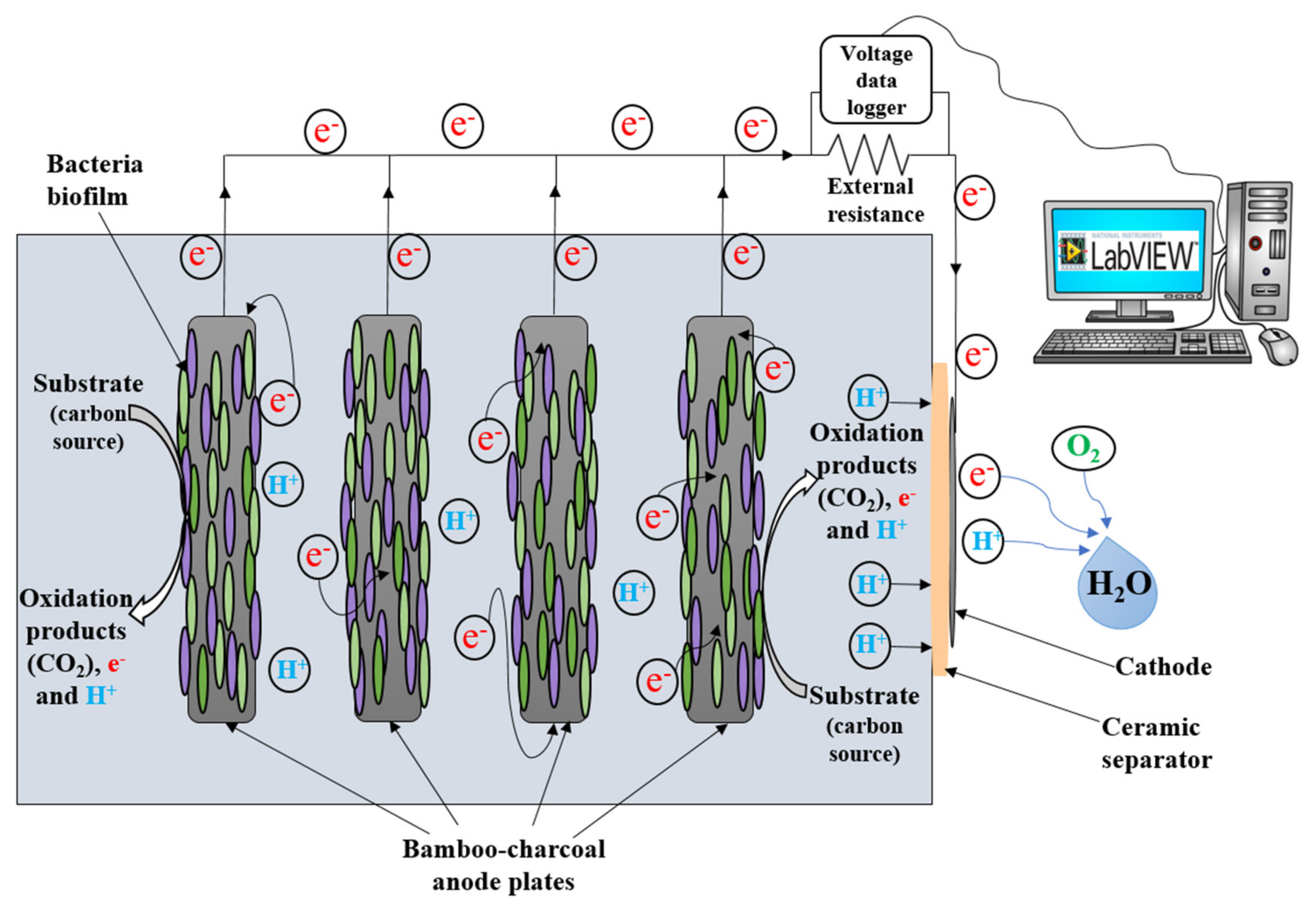
An MFC was designed and constructed with the method slightly modified from our previous study [26] (Figure 1). A rectangular-based single-chamber MFC (outer dimension of 13 cm length × 9 cm width × 11 cm height) was fabricated using clear acrylic sheets. A circular opening (3 cm diameter) in one of the sidewalls of the chamber allows the cathode to be exposed to the air. A ceramic separator (0.4 cm thickness) was placed between the anolyte and the cathode. Two small holes were drilled into the top wall of the chamber, which functioned as the inlet and outlet ports of the anolyte. The bamboo charcoal’s porous provided a large surface area for microbial cell attachment and biofilm growth [26]. The anode consisted of four conductive bamboo charcoal (BC) plates (Mt Meru Pte Ltd., Singapore). To connect the anode to the external circuit wire, stainless steel wire was attached to each of the BC plates. The BC plates were spaced approximately 2 cm from each other and 3 cm from the sidewalls of the chamber. The effective volume of the MFC (i.e., anode chamber) was approximately 530 mL.
A ceramic membrane was used as a separator between the anolyte and the cathode. Natural Peruvian clay was used to make the ceramic separator. First, the clay was molded in a circular shape (5.7 cm diameter, 0.4 cm thickness), and dried at room temperature. Second, the dried clay plate was matured at different temperatures (i.e., 100 °C, 300 °C, 600 °C, and 900–950 °C for 2 h at each temperature) for a total of 8 h in a muffle furnace (M10A-2A, Blue M Electric Company, Blue Island, IL, USA). Ceramic is known to have high physical strength, rigid nature, ability to withstand extreme chemical conditions, and low cost [34]. The cathode (one side geometric surface area of 6.7 cm2) was made using platinum-coated carbon cloth (0.2 mg/cm2 20% Pt on Vulcan-cloth; FuelCellsEtc, College Station, TX, USA). The cathode was connected with a stainless steel wire and placed outside of the ceramic separator. The electrodes were wired with insulated copper wires (external circuit).
It was expected that wastewater treatment was accomplished in the anaerobic chamber of the MFC, catalyzed by the EAB capable of oxidizing organic compounds to produce proton (H+), electron (e), and carbon dioxide (CO2), and stabilize residuals. The electrons flow through the external circuit to the cathode, and H+ migrate through the anolyte to the cathode where H+, O2, and e are combined (O2 is reduced) to form water (H2O), completing the circuit to generate electricity (Figure 2).

2.2. MFC—Hydroponic System

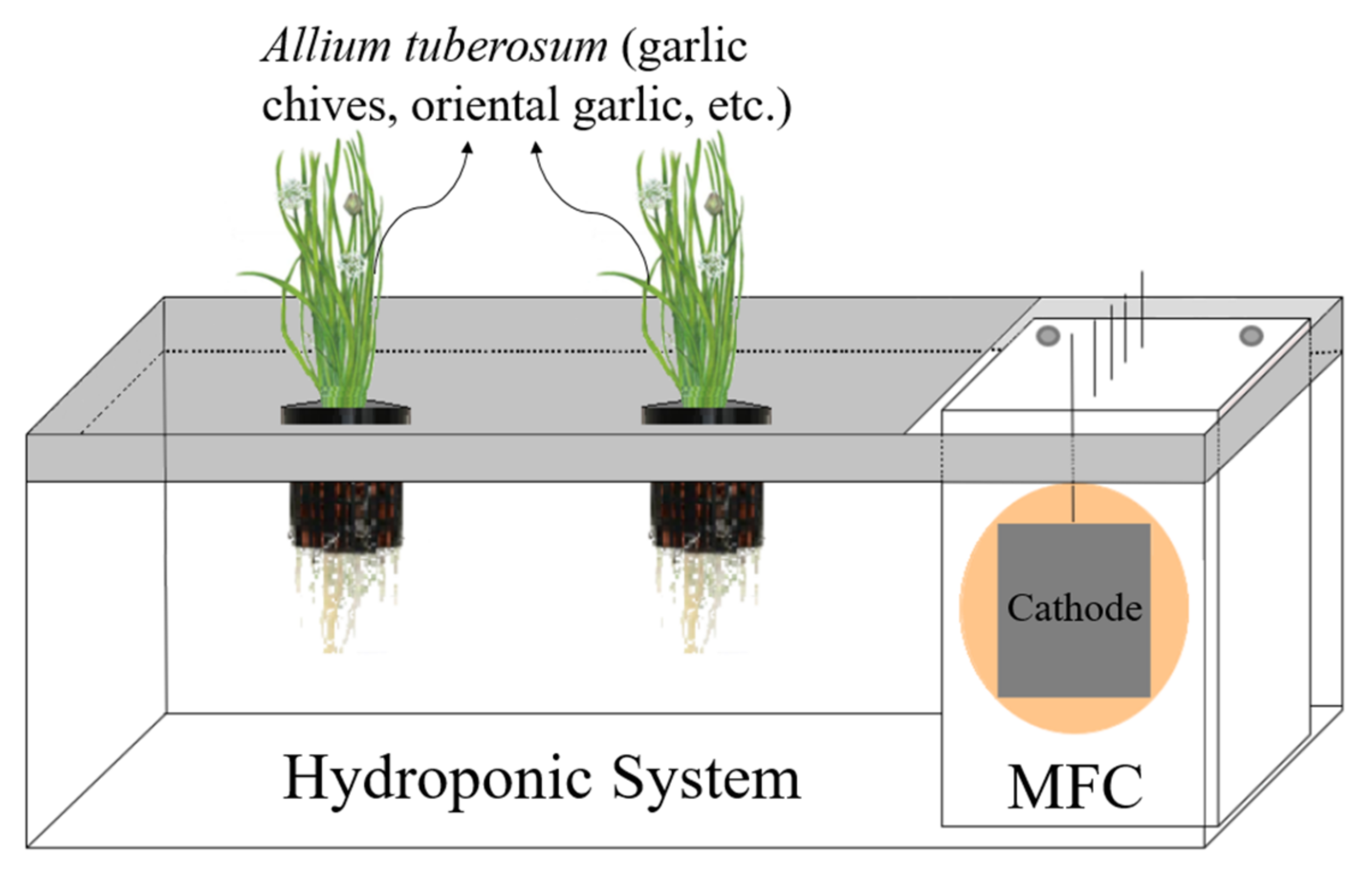
The hydroponics vessel was made of a plastic container (33 cm length, 20 cm width, 11.5 cm height). Three holes were made on a lid; namely, a rectangular opening (12 cm × 8.5 cm) for housing the MFC and two circular openings (7.3 cm diameter) for placing net pots to support the hydroponic plant Allium tuberosum. A. tuberosum is an edible plant generally called garlic chives, Oriental garlic, Asian chives, Chinese chives, or Chinese leek. Before being used, the plant had been kept hydroponically in the lab for over a year, thus it was adapted to the water environment.
The MFC was integrated into hydroponics (MFC-Hyp system) as shown in Figure 3. The cathode of the MFC was partially submerged (i.e., 2.25 cm under water and 0.75 cm in air). The water volume of 2500 mL was maintained in the hydroponic (Hyp) vessel. The whole system, except for the plant, was covered with cardboard to maintain dark to prevent algal growth in the Hyp system. A rectangular window was made on the front side of the cardboard cover to periodically check the water level in the Hyp vessel (Figure S1). There was no intentional mixing of water and wastewater in the Hyp and MFC, respectively. It was expected that the nutrients in ionic forms (e.g., HPO42−, PO43−, and NH4+) in wastewater diffuse from the MFC chamber to the Hyp vessel through the ceramic separator and cathode membrane of the MFC. In the Hyp vessel, NH4+ was oxidized to NO3 by nitrifying bacteria, and both PO43− and NO3 were taken by the plants.

2.3. Bacterial Culture and Substrate Wastewater

Synthetic potato wastewater was used as substrate (i.e., anolyte, feed), which was prepared using concentrated potato extract obtained from a local food processing plant in Pocatello, Idaho, USA. The potato extract was diluted with a phosphate buffer (pH 7) and DI water to a chemical oxygen demand (COD) level of ~3000 mg/L. The solution (pH 7.22 ± 0.028) was autoclaved for 20 min at 121 °C and stored at 4 °C until used. The conductivity of the substrate solution was 52 mS/cm.
The original source of bacteria was the anaerobic digester at the municipal wastewater treatment plant (Pocatello, Idaho), and the culture was acclimated in the MFC reactors and maintained in the laboratory for a number of years [26,35,36]. The mixed bacteria are predominantly Proteobacteria, Firmicutes, and Bacteroidetes [36].

2.4. MFC-Hyp System Operation, Monitoring, and Analyses

All experimental runs were carried out at room temperature (~20 °C). In the preliminary phase, 250 mL of seed bacterial culture was added to the MFCs and filled with fresh synthetic potato wastewater. Initially, the MFCs were run individually outside of the hydroponic system; during which biofilms were formed on the surface of the BC anodes. After two weeks of the preliminary run, the MFCs began to produce stable and reproducible voltage.
In the start-up phase, the MFC was emptied, filled with fresh wastewater (substrate) solution, and placed in the Hyp reservoir to form the novel MFC-Hyp system. Each MFC-Hyp system was run in two stages. The first stage was the control run without A. tuberosum, followed by the second stage run with A. tuberosum. Each stage lasted 28 days and was repeated twice.
Before samples were taken from the system, the water in the Hyp reservoir was uniformly mixed using a stirrer (Nuova II, Thermolyne, USA). All samples were prefiltered with a 0.2-μm filter (Millex-VV, Millipore, Guyancourt, France) before the chemical analyses. The COD and concentrations of ammonium, nitrate, and phosphate were determined using the wet chemistry/spectrophotometric methods using a spectrophotometer (HP 8453 UV-visible G1103A, Agilent Technologies, Santa Clara, CA, USA). The methods from the literature were adapted and modified if necessary. COD was determined by the modified EPA Standard Method 5220 D using HACH digestion vials (HACH Company, Loveland, CO, USA). The method proposed by Holmes et al. (1999) [37] and Solόrzano, (1969) [38] was modified for the analysis of ammonium (NH4+). The EPA Method 352.1 was followed for nitrate (NO3). The assay method by Chen et al. (1956) [39] was modified for the analysis of phosphate (PO43−). All samples were analyzed in triplicate. Microsoft Excel 16 was used for data analysis. The statistical results were expressed as means ± standard error (n = 3).
The anode and cathode electrodes of the MFC were connected through a resistor (~1000 ohm) and the potential drop (V) across the external load (Rload) was measured. The voltage produced by the MFC-Hyp system was recorded every 15 min using a data acquisition system (DAS) operated by the LabVIEW software. The resultant current (I) was calculated by Ohm’s law (i.e., I = V/Rload). The power P was calculated by P = I⋅V or P = V2/Rload. The calculated current and power were normalized to the cathode surface area to determine the current and power densities.

3. Results

3.1. MFC-Hyp Performance

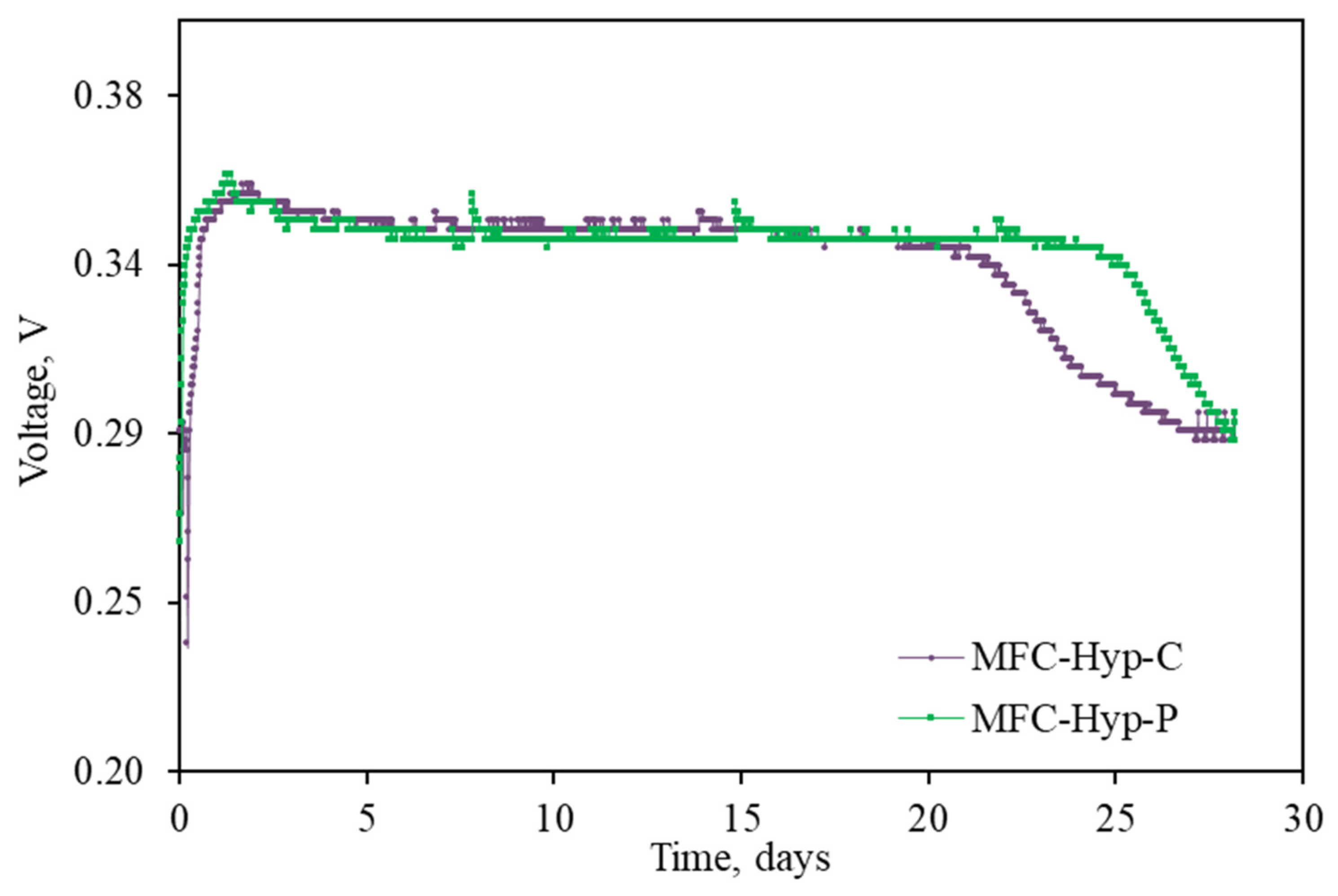
Each MFC-Hyp system with and without the plant A. tuberosum was run for 28 days. Figure 4 shows the voltage produced by both systems with a ~1000 Ω resistor. The legends MFC-Hyp-P and MFC-Hyp-C represent the MFC-Hyp systems with and without (control) the plant, respectively. As is seen, both systems consistently produced about 0.35 V; however, the duration of the system with A. tuberosum (MFC-Hyp-P) was approximately one week longer than that without the plant (MFC-Hyp-C).
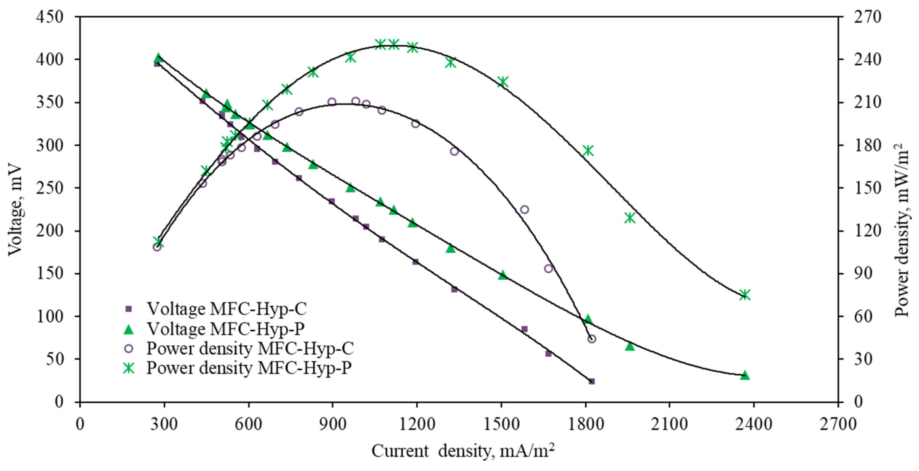
The polarization and power density curves were developed by varying the external resistance from 20 to 2150 Ω. Both power density and current density were calculated based on the geometric surface area of the cathode (i.e., 6.7 × 10⁻⁴ m2). As is seen in Figure 5, the power density produced by the MFC-Hyp system with A. tuberosum was distinctively larger than that produced by the control system. The maximum power density produced by the system with A. tuberosum was 250.7 mW/m2 at a current density of 1069.7 mA/m2, whereas the maximum power density yielded by the control (without A. tuberosum) system was 210.7 mW/m2 at a current density of 980.6 mA/m2. The maximum voltage and maximum current density with A. tuberosum were 403 mV and 2367.9 mA/m2, respectively; while the control system produced 396 mV and 1821.6 mA/m2, respectively. The values of internal resistance determined according to the maximum power transfer theorem [40] are ~330 Ohm in the MFC-Hyp with or without the plant, and ~110 Ohm when the MFC was run alone (uncoupled from the Hyp).

3.2. Nutrient and COD Removal

The MFC chamber was interfaced with the Hyp vessel through a ceramic separator. Carbon dioxide (CO2), carbonate species (e.g., CO32−, HCO3), and nutrients (e.g., PO43−, NH4+) in the MFC chamber are expected to diffuse to the Hyp vessel through the separator due to the concentration gradient and/or electric field created by the MFC. The nutrients and CO2 are assumed to be utilized by A. tuberosum in the Hyp vessel. The nutrient removal from the wastewater occurred in the MFC chamber of the MFC-Hyp system. The concentrations of nutrients and COD in the MFC-Hyp are presented in Table S1.
The nutrient and COD removal efficiencies in the MFC were calculated using the formula: E = [(Co − Ct)/Co] × 100; where E is the removal efficiency (%), and Co and Ct are the concentrations (mg/L) of the constituents in the MFC at time t = 0 (i.e., the constituents in feed wastewater) and at t = 28 days, respectively. The removal efficiencies of COD, phosphate, and nitrate were 80.4 ± 1.39%, 11.4 ± 0.02%, and 31.7 ± 0.17%, respectively, in the MFC-Hyp system with A. tuberosum, while 78.7 ± 1.66%, 8.9 ± 0.08%, and 28.9 ± 0.10%, respectively, in the control system. It is noteworthy that, in the MFC chamber, the concentration of ammonium increased from 6.6 ± 0.62 mg/L to 41.34 ± 3.74 mg/L in the presence of A. tuberosum and 5.5 ± 0.16 mg/L to 64.76 ± 1.08 mg/L in the control system. The smaller increase in the ammonium concentration in the MFC in the presence of A. tuberosum in the Hyp may indicate that the diffusion of ammonium from the MFC to the Hyp was increased due to the decrease in the ammonium level in the Hyp section (Table S1). The lower ammonium level in the Hyp might have occurred owing to enhanced nitrification and nitrate uptake by A. tuberosum. Previous researchers have shown that plants in the cathode region could be beneficial for ammonium removal and bioelectricity generation [25,41,42]. Undoubtedly, further studies are required to fully understand the nitrogen removal pathways in the MFC-Hyp system.

3.3. Phosphate Recovery

In this study, the mass of phosphate transported from the MFC to the Hyp vessel was considered to be recovered. As phosphate is not involved in redox reactions, it could be exclusively recovered from the wastewater [17]. It was considered that the MFC-Hyp system is a closed system consisting of four major components relevant to phosphate (Figure 6): (a) the mass of phosphate in wastewater (mww) and in bacteria (mb) in the MFC; and (b) the mass of phosphate present in water (mw) and taken up by plants (mp) in the Hyp vessel.
As the MFC-Hyp is a closed system and the mass of phosphate is assumed to be conserved, the phosphate mass at Day 0 (t = 0 days) equals the phosphate mass at Day 28 (t = 28 days); thus,
(mww + mb + mw + mp)t=0 = (mww + mb + mw + mp)t=28
where (mww)t=0 and (mww)t=28 are the phosphate mass in wastewater in the MFC at Day 0 and 28, respectively; (mb)t=0 and (mb)t=28 are the phosphate mass in bacteria in the MFC at Day 0 and 28, respectively; (mw)t=0 and (mw)t=28 are phosphate mass in water in the Hyp vessel at Day 0 and 28, respectively; and (mp)t=0 and (mp)t=28 are the phosphate mass in plants in the Hyp vessel at Day 0 and 28, respectively.
Since (mb + mw + mp)t=0 is negligible, (mww)t=0 is the total mass of phosphate in the MFC-Hyp system, and Equation (1) becomes:
mT = (mww)t=0 = (mww + mb + mw + mp)t=28
where mT is the total mass of phosphate in the MFC-Hyp system. Since phosphate was not detected in the Hyp vessel initially (at t = 0 day), mT is the total phosphate in the feed wastewater in the MFC. The mass of phosphate taken by bacteria at Day 28, (mb)t=28, is given by rearranging Equation (2):
(mb)t=28 = (mww)t=0 − (mww + mw + mp)t=28
In the control system, there were no plants, thus, (mp)t=28 = 0, and Equation (3) is reduced to Equation (4).
(mb)t=28 = (mww)t=0 − (mww + mw)t=28
It can be assumed that the mass of phosphate taken by bacteria in the MFC (i.e., (mb)t=28) is not affected by the presence of plants in the Hyp vessel. Under this assumption, the mass of phosphate taken by the plants (i.e., (mp)t=28) in the Hyp vessel can be calculated by adapting the value of (mb)t=28 in the control run and using Equation (4).
(mp)t=28 = (mww)t=0 − (mww + mw + mb)t=28
The masses of phosphate in the individual components are presented in Table S2.
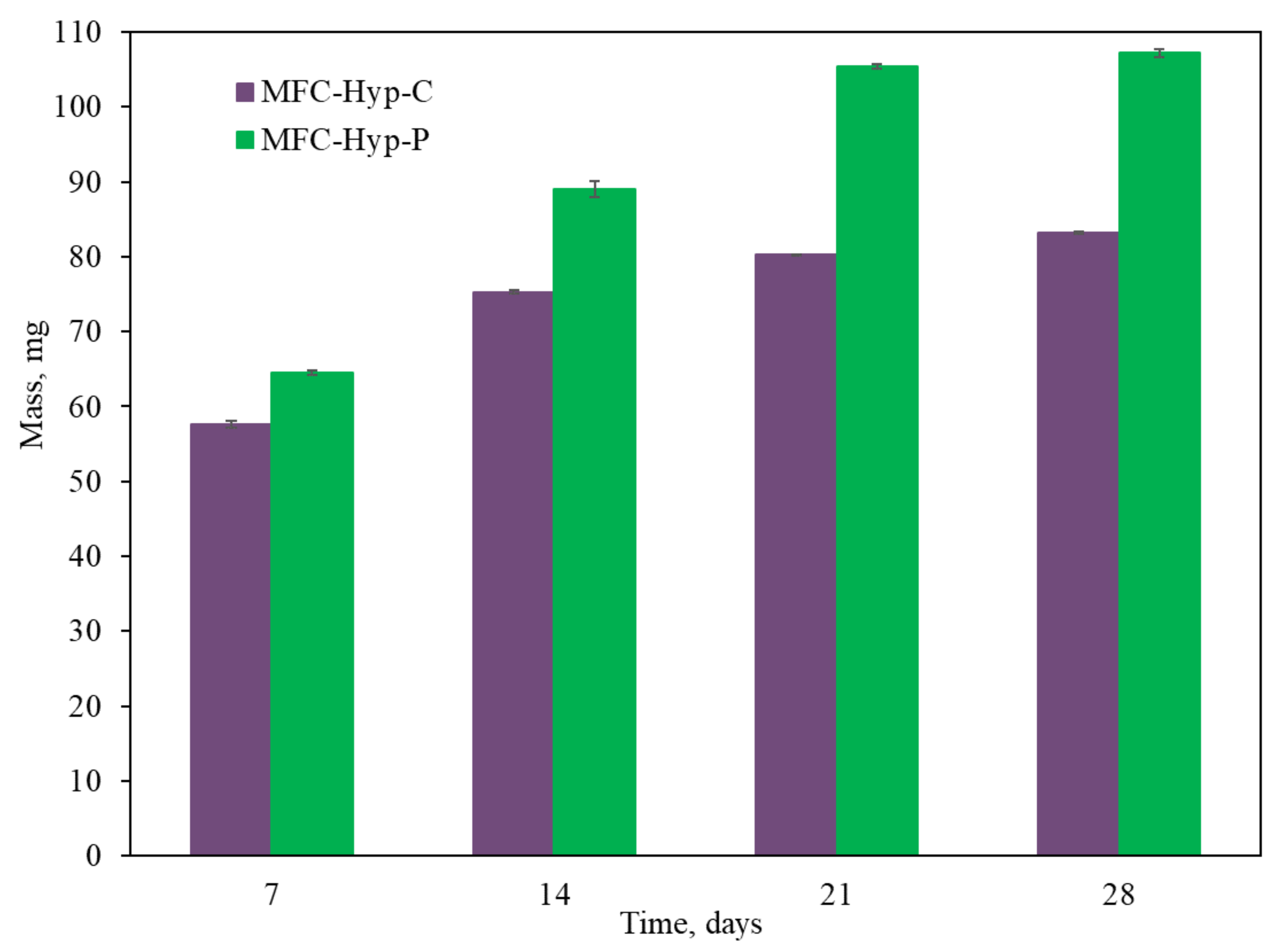
Moreover, Figure 7 shows temporal changes in the phosphate mass (mg) in water in the Hyp vessel with and without A. tuberosum during the 28 days of operation. The result shows that the phosphate mass was increased in the Hyp vessel and its increase is clearly larger with A. tuberosum, compared to that in the control system.
The percent recovery was calculated by the formula: %PO4 recovery = [(mw)t=28d/mT] × 100; where mT is the total phosphate mass (mg) in the system and (mw)t=28d is the mass of phosphate diffused from the MFC to the Hyp vessel, measured at Day 28. After 28 days of operation, phosphate recovered from the wastewater was 4.9 ± 0.02% in the control system and 7.5 ± 0.88% in the system growing A. tuberosum. A. tuberosum absorbed 1.4 ± 0.82% of the total available phosphate.

3.4. Plant Biomass

To examine the effect of the MFC on the plant growth, A. tuberosum that had grown outside the MFC-Hyp system was placed in the MFC-Hyp system (Figure S2). Pot P1 was placed near the MFC (~3.3 cm away) and Pot P2 was placed far (~13.9 cm away) from the MFC. In addition, A. tuberosum was grown in a vessel containing DI water as control (CP) in the absence of the MFC. The change in the plant biomass was measured in length on Day 0 and Day 28. The measurement of the plant samples was made in duplicate (n = 2). During 28 days of the run, A. tuberosum in the pot P1 grew, on average, 6.6 cm, while A. tuberosum in the pot P2 grew 6.9 cm, on average. On the other hand, the control plant (CP) only grew, on average, 2.4 cm. Moreover, longer roots were developed in the pots P1 and P2 in the MFC-Hyp system, compared to that in the control system (See Figure S3).

3.5. Coulombic Efficiency

The Coulombic efficiency (CE) of the MFC was computed using the formula [43]:
C E = M   I   t F   b   v a n   Δ C
where M is the molecular weight of substrate (32 g O2/mol for substrate); I is the current in mA; t is the duration of a cycle in hrs; F is the Faraday constant (96,500 Coulombs/mol of e); b is the number of moles of e transferred per mole of the substrate (4 mol e/mol); van is the anode volume in a liter (L); ΔC is the change in substrate concentration (measured as COD in g/L). During the 28-day run, the MFC-Hyp system with A. tuberosum produced an average current I of 0.349 mA and ΔC of 2.8 g COD/L, yielding a CE of 4.8%. On the other hand, the control system produced an average current of 0.344 mA and ΔC of 2.4 g COD/L and yielded a CE of 5.5%.

4. Discussion

The present study examined the removal of organics (as COD), phosphate, and nitrate from wastewater in the MFC-Hyp system. After 28 days of the treatment with the MFC-Hyp growing A. tuberosum, the removal of COD, phosphate, and nitrate, that occurred in the MFC, were 80.4 ± 1.39%, 11.4 ± 0.02%, and 31.7 ± 0.17%, respectively. The phosphate recovery was calculated to be 7.5 ± 0.88% in the MFC-Hyp growing A. tuberosum.
The concentrations of COD, phosphate, and nitrate are 672.3 ± 3.38 mg/L, 2931.5 ± 0.79 mg/L, and 22.12 ± 0.01 mg/L, respectively, in the MFC, and 20 ± 3.22 mg/L, 42.9 ± 0.2 mg/L, and 7.6 ± 0.11 mg/L, respectively, in the Hyp vessel after 28 days of run. The U.S. EPA’s recommended limit for total phosphates is 0.05 mg/L in a stream that enters a lake and 0.1 mg/L in flowing water to control eutrophication [44]. In a free water surface wetland, typical influent concentrations of BOD, NH3/NH4 as N, NO3 as N, total nitrogen (TN), and total phosphorus (TP) are 5–100 mg/L, 2–20 mg/L, 2–10 mg/L, 2–20 mg/L, and 1–10 mg/L, respectively, while the target effluent concentrations are 5–30 mg/L, 1–4 mg/L, 2–9 mg/L, 2–9 mg/L, and 1–4 mg/L, respectively [45]. The results from the present study suggest that further treatment is necessary to meet the regulatory levels for discharging treated wastewater to receiving water bodies or reusing it for irrigation, recharging groundwater, and other water supply purposes.
Table 1 summarizes the past studies of the MFC-Hyp and similar systems in terms of their performances, operational conditions, and types of wastewater and aquatic plants. Only a limited number of studies on integrated MFC-Hyp systems have been found. In the studies by [46,47], wastewater (either treated or untreated) was directly introduced into the Hyp system. Owing to public health concerns, such systems are not suitable for growing edible plants. The present study indicated that the ceramic separator (that was placed at the interface between the anode chamber and the cathode) could block the migration of biotic and abiotic particles from the MFC to the Hyp system. As ceramics can retain bacteria and are subject to less fouling compared to synthetic membranes, ceramic membranes have been used for the disinfection of drinking water in some regions of the world [48,49,50]. Nonetheless, the studies that focused on ceramic separators in the MFC-Hyp systems are lacking.

4.1. MFC-Hyp Performance

The present study revealed that the performance of the MFC-Hyp system was improved in the presence of A. tuberosum. With A. tuberosum, the MFC-Hyp produced a maximum voltage of 403 mV, a maximum current density of 2367.9 mA/m2, and a maximum power density of 250.7 mW/m2. Past studies have also shown that plants could enhance the generation of bioelectricity in the MFC-Hyp systems. Particularly, the presence of plants in the cathodic zone has been shown to be beneficial for power generation, as the plants release oxygen into the root zone through their aerenchyma tissue [52]. Using drip hydroponics (growing Cymbopogon citratus) coupled with multiple MFCs, Yadav et al. (2020) [47] treated domestic wastewater. In their study, the drip Hyp-MFCs in series produced the maximum voltage and maximum current density of 1490 ± 91 mV and ~36 mA/m2 (normalized to the cathode surface area), respectively, while the drip Hyp-MFCs in parallel produced the maximum voltage and maximum current density of 15.80 ± 5 mV and ~458 mA/m2, respectively. Both systems with the in-series MFCs and parallel MFCs produced a maximum power density of 31.9 mW/m2. The maximum power density and the maximum current density produced in the present study are considerably larger than those reported by Yadav et al. (2020) [47]. Colares et al. (2021) [51] treated urban wastewater using a floating treatment wetlands-MFC with Canna generalis, Chrysopogon zizanioides, Cyperus papyrus Nanus, Hymenachne grumosa, and Equisetum hyemale. These plants were placed in floating supports and connected in parallel. Their system produced a maximum voltage of 108 mV, which is significantly less than that produced in the present work. Yang et al. (2021) [42] treated synthetic nutrient-rich wastewater using a floating bed-MFC system with Cyperus alternifolius Linn. subsp. flabelliformis (Rottb.) Kukenth (windmill grass), Ceratophyllum demersum Linn. (goldfish algae), Eichhornia crassipes (Mart.) Solms Pontereia crassipes Mart. (water hyacinth), and Ipomoea aquatic Forssk (water spinach). In their system with the plants, the average voltage was increased by 26.2–62.63%, compared to the system without the plants. Among all the plants, Ipomoea aquatic Forssk produced the largest power output (the maximum power density of 6.03mW/m2 of electrode surface area) and nitrogen removal. The system with and without water spinach produced an average voltage of 161 mV and 99 mV, respectively [42]. The variations in the system outputs are likely due to the differences in the experimental conditions such as types of electrodes and wastewater, and the design and operation of the systems.

4.2. Nutrient and COD Removal

Khuman et al. (2020) [46] treated synthetic wastewater using the upflow hydroponic CW-MFCs with a ceramic separator. In their system with Canna indica, the wastewater was treated first in the anodic compartment for 12.8 h and treated further in the cathodic zone. Their system produced a maximum COD removal efficiency of 53.9% in the anodic zone and 86.2 ± 8.1% overall in the run time of ~27 days. Using a closed floating treatment wetland-MFC without any separators, Colares et al. (2021) [51] treated urban wastewater in the presence of five different plant species (Canna generalis, chrysopogon zizanioides, Cyperus papyrus Nanus, Hymenachne grumosa, and Equisetum hyemale). In their study, the removals of COD, TP, and TN were 71.4%, 11.4%, and 8.4%, respectively, with a retention time of seven days for three weeks (seven days/cycle, a total of three cycles). The COD removal efficiencies (71.4%) reported by Colares et al. (2021) [51] are lower than the removal (80.4%) produced in the present study, while the phosphate removal efficiencies in their study and the present study are at the same level (11.4%). It should be noted that the run time of the present study was 28 days as compared to 21 days in the work by Colares et al. (2021) [51]. The low phosphate removal found in both studies may be due to the low plant uptake. The low nitrogen removal in the study by Colares et al. (2021) [51] was likely attributed to the low dissolved oxygen (DO) levels in their system as DO plays an important role in nitrification and consequently in the nitrogen removal in a water environment [53].
Yang et al. (2021) [42] studied four different plant species (Cyperus alternifolius Linn. subsp. flabelliformis (Rottb.) Kukenth, Ceratophyllum demersum Linn., Eichhornia crassipes (Mart.) Solms Pontereia crassipes Mart., Ipomoea aquatic Forssk) individually, in the ecological floating bed-MFC with no separators. In treating nutrient-rich synthetic water with the HRT of two days, they obtained the highest removal of COD and TN of 82.49% and 55.6%, respectively, in the system with Ipomoea aquatic Forssk. Yadav et al. (2020) [47] treated domestic wastewater collected from the primary sedimentation tank using the drip hydroponics-MFC with no separators. In the presence of Cymbopogon citratus supported by a cocopeat matrix, they obtained the COD removal efficiencies of 72 ± 2.4% and 85.7 ± 0.6% at the HRT of 3 h and 12 h, respectively, and the phosphate removals of 83.2 ± 1.1% and 85.8 ± 0.6% at the HRT of 3 h and 12 h, respectively. Their system accomplished comparable COD and nutrient removal in shorter periods of time, compared to the present study with the MFC-Hyp system. The high phosphate removal efficiencies presented by the drip hydroponic-MFC system can be attributed to high microbial uptake, physical adsorption by the cocopeat matrix, and electrochemical reaction at the electrode. Nevertheless, the power output (31.9 mW.m−2 in series and parallel) by the drip hydroponic-MFC system was considerably lower than those produced by other systems previously discussed. Overall, based on past studies with various types of integrated MFC-Hyp systems, the presence of plants does not seem to considerably affect the COD removal efficiency. The removal of nitrogen and phosphorus requires further investigation to fully understand their removal pathways. In the MFC-Hyp systems, nitrogen removal occurs through multiple mechanisms such as plant absorption, root exudation, enzymatic activities, and electricity generation [42], and similarly, phosphorus removal is promoted by the microbial and plant uptake, physical adsorption, and electrochemical reactions [47]. It is noteworthy that the past studies discussed previously have not focused on nutrient recovery. The present study found that the recovery of phosphate was 7.5 ± 0.88% in the presence of A. tuberosum; of which 1.4 ± 0.82% of the total phosphorus was taken by A. tuberosum.

4.3. Plant Biomass

According to Sapkota et al. (2019) [54], the yields and qualities of plants are determined by compositions of macro- and micro-nutrients in hydroponics. However, excessive nutrient levels can cause nutrient antagonism that can result in deficiencies of other nutrients in plants [55]. For example, an excess level of potassium in water in the Hyp system can result in antagonism with nitrogen and other nutrients causing nitrogen deficiency in plants. Moreover, high phosphorus levels can induce iron and zinc deficiency in plants [55]. Plants require all sorts of essential elements (e.g., phosphorus, nitrogen, potassium, oxygen, etc.) to produce high crop yields. Therefore, it is important to ensure that water in hydroponics contains an optimum dose of essential elements. For the effective use of the nutrients recovered from wastewater, further studies need to be conducted to determine the optimum nutrient levels for the growth of A. tuberosum.
In a study on nutrient removal, Colares et al., (2021) [51] found that plant uptake did not seem to play an important role in the removal of TP and TN. Their findings are consistent with the results from the present study (i.e., A. tuberosum took only 1.4 ± 0.82% of available phosphate). Colares et al. (2021) [51] estimated that the plant’s uptake and incorporation into the biomass were responsible for the removal of only 0.825% and 1.05% of the inflow TN and TP loadings, respectively. Vymazal (2007) [53] indicated that nitrogen uptake and storage in plant tissues are highly dependent on the plant species.
Growing plants that have high commercial values provide an additional incentive to the MFC-Hyp system, in addition to the functions of nutrient removal, bioelectricity generation, and wastewater treatment. Further investigation is recommended to identify plants that have the ability to take up a large number of nutrients rapidly as well as high commercial values. In the MFC-Hyp system, hydroponic plants are expected to sequester CO2 generated via the degradation of organics in the MFC as well as CO2 in the atmosphere and fix it in a form of biomass. Thus, the MFC-Hyp system is a low carbon footprint wastewater treatment technology that can contribute to achieving net zero CO2 emissions among other benefits (i.e., food production, electricity generation).

4.4. Coulombic Efficiency (CE)

The Coulombic efficiency (CE) is an important parameter to evaluate the energy recovery efficiency of the system. The CE values found in this study fall in the CE range reported by Oon et al. (2017) [56]. They treated synthetic wastewater using the up-flow CW-MFC and found that the CE values were in a range between 0.08% and 10.28% with the plant Elodea nuttallii. Similarly, Saz et al. (2018) [57] studied the CW-MFC using synthetic wastewater. Their system with four different plants, namely, Typha latifolia, Typha angustifolia, Juncus gerardii, and Carex divisa, provided the CEs of 6.074 ± 8.42%, 8.28 ± 10.4%, 6.57 ± 6.84%, and 6.13 ± 5.68%, respectively, and 4.64 ± 5.84% without the plant (control). On the other hand, a considerably lower CE value (0.386%) was reported by Liu et al. (2019) [58] who studied the vertical flow CW-MFC with the plant Canna indica, feeding swine wastewater. The CE values approximately between 1% to 1.9% were reported by Srivastava et al. (2020) [59] who treated synthetic wastewater using the MFC-horizontal subsurface CW with Canna indica.
The CE is closely related to the COD removal [58]. The lower CE value indicates that a larger fraction of the chemical energy contained in the substrate (organic matter) was not converted to electrical energy [57,58]. The lower CE also indicates that fewer electrochemical active bacteria (EAB) were involved in the direct electron transfer to the anode, while non-electrogenic bacteria were in a competitive mode with the EAB for substrate [56]. Further studies should be performed to evaluate the effectiveness of the plant on different bacteria species and optimize the EAB population in the system.

4.5. Ceramic Separator

As a means of physical separation of the anode and cathode in the MFC, ceramic materials have been used as a suitable replacement for expensive synthetic membranes [60,61,62]. The ceramic separator serves as a partition between the anode and cathode and also between the MFC and the hydroponics. In the present study, natural Peruvian clay, with no additional ingredients, was used to fabricate ceramic separators. Khuman et al. (2020) [46] used a ceramic separator made of red soil with 20% montmorillonite as a proton exchanger and studied the up-flow hydroponic CW-MFC having a Styrofoam float system to support the plant Canna indica rhizome without media. The two systems (with and without a ceramic separator) fed synthetic sucrose-based wastewater produced a higher voltage (~900 mv) with the ceramic separator than that (~800 mV) without the ceramic separator. These voltage values are considerably higher than the voltages produced in the MFC-Hyp system in the present study. According to Khuman et al. (2020) [46], a ceramic separator enables better anaerobicity to support substrate utilization by electrogenesis in the anodic zone and prevent oxygen diffusion; thus, the ceramic separator can improve energy generation.
Nafion-117 is the most common polymer-based proton exchange membrane (separator) used in MFC construction. The major drawbacks associated with the Nafion separator are high cost, low mechanical stability, and sulfide poisoning under field conditions [46]. These properties are problematic for large-scale implementations of the MFC-Hyp systems. Compressed glass wool has also been investigated as a potential separator [63,64]. Because the compressed glass wool is not completely impervious, it has the following disadvantages: (i) oxygen can diffuse from the cathode region to the anode region, and (ii) plant roots may penetrate into the interstice of the glass wool, leading to a rise in dissolved oxygen (DO) level in the anode region [65,66,67]. Further exploration including design optimization of ceramic separators is important for future research to improve the performance of the MFC-Hyp system.

5. Conclusions

As the world population grows, the demand for energy, food, freshwater, and wastewater treatment increases. Coupling an MFC and a Hyp system is a promising new technology to accomplish the removal of organics (wastewater treatment), generation of electricity (energy recovery), and growth of plants (nutrient recovery and food production) at the same time. In the present study, the novel integrated MFC-Hyp technology was designed, constructed, operated, and evaluated.
The maximum power density of 250.7 mW/m2 was produced in the presence of A. tuberosum, while 210.7 mW/m2 was in the absence of the plant. With A. tuberosum, the power output of the MFC increased by about 19%, and the removal efficiencies of nitrate, phosphate, and COD were also increased by 29–32%, 9–11%, and 79–80%, respectively. Moreover, the phosphorus recovery in the Hyp section of the MFC-Hyp system was 4.9% in the control system and increased to 7.5% in the presence of A. tuberosum.

6. Future Work

Although the MFC-Hyp design offers relatively easy operation and maintenance, further improvement is necessary for field implementations. Further investigation is recommended to identify plants that can take up a large number of nutrients rapidly and have high commercial values. To assure that the MFC-Hyp system is safe to grow edible plants, the ceramic separator must prevent harmful compounds and microbes from passing through it to the Hyp section. In the present study, Peruvian clay was used to fabricate the ceramic separator. It is recommended to study the addition of external minerals (e.g., aluminosilicate) to the base clay to improve its performance. It should be emphasized that the systems growing edible plants that do not have a separator between the anode and cathode regions allow direct contact between the plants and wastewater; thus, they may present an unacceptable human health risk. The MFC-Hyp system developed in the present study partitions the plants (in the Hyp vessel) and wastewater (in the MFC) using a ceramic separator, thus it can offer an important advantage of producing safe food products.
The MFC-Hyp system is a new promising technology; however, it requires further research work to fully understand its mechanisms. To effectively remove organics and recover energy and nutrients from wastewater in the MFC-Hyp system, it is important to understand: (i) the constituents’ pathways and transport mechanisms, especially, the diffusion of nutrient ions (e.g., PO43−, HPO32−, NH4+, NO3) and the carbonate species (e.g., CO32−, HCO3) through the ceramic separator; and (ii) effectiveness, suitability, and roles of the selected plants. Holistic research is needed to determine and optimize: (i) the design/construction parameters (i.e., type and size of the system, electrodes, and separators); (ii) operational parameters (e.g., wastewater feed rate, HRT, aeration rate); and iii) the biological parameters (e.g., plant growth rate, nutrient uptake rate, commercial value). The optimized MFC-Hyp system can represent an innovative new “carbon-neutral” energy technology that could become an important component of a diversified world energy-water-food security.

Supplementary Materials

The following supporting information can be downloaded at: https://www.mdpi.com/article/10.3390/en15239211/s1, Figure S1: The MFC-Hyp system: (a) without a cover; (b) with a cover; Figure S2: Pictorial view of control plant (CP), plant 1 (P1) and plant 2 (P2) in the MFC-Hyp system: (a) on the first day and (b) after 28 days of operation; Figure S3: Pictorial view of roots from (a) control plant (CP), (b) plant 1 (P1), and (c) plant 2 (P2); Table S1: Concentrations of nutrients and COD in the MFC-Hyp system; Table S2: Total available mass of phosphate (mT), mass of phosphate present in the wastewater (mww) and taken up by bacteria (mb) in the MFC, and in water (mw) and taken up by the plant (mp) in the Hyp vessel after the 28 days of operation.

Author Contributions

Conceptualization, N.E.P. and C.S.; methodology, N.E.P.; validation, C.S.; formal analysis, N.E.P.; investigation, N.E.P.; resources, C.S.; data curation, N.E.P. and C.S.; writing—original draft preparation, N.E.P.; writing—review and editing, N.E.P. and C.S.; visualization, N.E.P. and C.S.; supervision, C.S.; project administration, C.S.; funding acquisition, C.S. All authors have read and agreed to the published version of the manuscript.

Funding

This research received no external funding.

Data Availability Statement

The data presented in this study are available on request from the corresponding author. The data are not publicly available due to potential proprietary information.

Acknowledgments

The authors gratefully acknowledge the Graduate School, the Civil and Environmental Engineering Department, and the Center of Archaeology, Materials and Applied Spectroscopy (CAMAS) at Idaho State University for all their support.

Conflicts of Interest

The authors declare no conflict of interest.

References

  1. Jingyu, H.; Miwornunyuie, N.; Ewusi-Mensah, D.; Koomson, D. Assessing the factors influencing the performance of constructed wetland–microbial fuel cell integration. Water Sci. Technol. 2020, 81, 631–643. [Google Scholar] [CrossRef] [PubMed] [Green Version]
  2. Reddy, C.N.; Nguyen, H.T.; Noori, T.; Min, B. Potential applications of algae in the cathode of microbial fuel cells for enhanced electricity generation with simultaneous nutrient removal and algae biorefinery: Current status and future perspectives. Bioresour. Technol. 2019, 292, 122010. [Google Scholar] [CrossRef] [PubMed]
  3. UN Environment Annual Report 2017. Available online: https://www.unep.org/annualreport/2017/index.php (accessed on 7 January 2022).
  4. Tilman, D.; Balzer, C.; Hill, J.; Befort, B.L. Global food demand and the sustainable intensification of agriculture. Proc. Natl. Acad. Sci. USA 2011, 108, 20260–20264. [Google Scholar] [CrossRef] [PubMed] [Green Version]
  5. You, J.; Greenman, J.; Melhuish, C.; Ieropoulos, I. Electricity generation and struvite recovery from human urine using microbial fuel cells. J. Chem. Technol. Biotechnol. 2016, 91, 647–654. [Google Scholar] [CrossRef]
  6. Zhou, Y.; Wang, L.; Zhou, Y.; Mao, X.Z. Eutrophication control strategies for highly anthropogenic influenced coastal waters. Sci. Total Environ. 2020, 705, 135760. [Google Scholar] [CrossRef]
  7. Cordell, D.; Rosemarin, A.; Schröder, J.; Smit, A. Towards global phosphorus security: A systems framework for phosphorus recovery and reuse options. Chemosphere 2011, 84, 747–758. [Google Scholar] [CrossRef]
  8. Ye, Y.; Ngo, H.H.; Guo, W.; Chang, S.W.; Nguyen, D.D.; Liu, Y.; Nghiem, L.D.; Zhang, X.; Wang, J. Effect of organic loading rate on the recovery of nutrients and energy in a dual-chamber microbial fuel cell. Bioresour. Technol. 2019, 281, 367–373. [Google Scholar] [CrossRef]
  9. Erisman, J.W.; Sutton, M.A.; Galloway, J.; Klimont, Z.; Winiwarter, W. How a century of ammonia synthesis changed the world. Nat. Geosci. 2008, 1, 636–639. [Google Scholar] [CrossRef]
  10. Geerts, S.; Marchi, A.; Weemaes, M. Full-scale phosphorus recovery from digested wastewater sludge in Belgium—Part II: Economic opportunities and risks. Water Sci. Technol. 2015, 71, 495–502. [Google Scholar] [CrossRef]
  11. Marchi, A.; Geerts, S.; Weemaes, M.; Wim, S.; Christine, V. Full-scale phosphorus recovery from digested wastewater sludge in Belgium-part I: Technical achievements and challenges. Water Sci. Technol. 2015, 71, 487–494. [Google Scholar] [CrossRef]
  12. Mihelcic, J.R.; Fry, L.M.; Shaw, R. Global potential of phosphorus recovery from human urine and feces. Chemosphere 2011, 84, 832–839. [Google Scholar] [CrossRef]
  13. Shannon, M.A.; Bohn, P.W.; Elimelech, M.; Georgiadis, J.G.; Mariñas, B.J.; Mayes, A.M. Science and technology for water purification in the coming decades. Nature 2008, 452, 301–310. [Google Scholar] [CrossRef]
  14. Freguia, S.; Logrieco, M.E.; Monetti, J.; Ledezma, P.; Virdis, B.; Tsujimura, S. Self-Powered Bioelectrochemical Nutrient Recovery for Fertilizer Generation from Human Urine. Sustainability 2019, 11, 5490. [Google Scholar] [CrossRef] [Green Version]
  15. Ge, Z.; He, Z. Long-term performance of a 200 liter modularized microbial fuel cell system treating municipal wastewater: Treatment, energy, and cost. Environ. Sci. Water Res. Technol. 2016, 2, 274–281. [Google Scholar] [CrossRef] [Green Version]
  16. Ye, Y.; Ngo, H.H.; Guo, W.; Chang, S.W.; Nguyen, D.D.; Zhang, X.; Zhang, S.; Luo, G.; Liu, Y. Impacts of hydraulic retention time on a continuous flow mode dual-chamber microbial fuel cell for recovering nutrients from municipal wastewater. Sci. Total Environ. 2020, 734, 139220. [Google Scholar] [CrossRef]
  17. Kelly, P.T.; He, Z. Nutrients removal and recovery in bioelectrochemical systems: A review. Bioresour. Technol. 2014, 153, 351–360. [Google Scholar] [CrossRef]
  18. Chen, X.; Sun, D.; Zhang, X.; Liang, P.; Huang, X. Novel Self-driven Microbial Nutrient Recovery Cell with Simultaneous Wastewater Purification. Sci. Rep. 2015, 5, 15744. [Google Scholar] [CrossRef] [Green Version]
  19. Gardner-Dale, D.; Bradley, I.; Guest, J. Influence of solids residence time and carbon storage on nitrogen and phosphorus recovery by microalgae across diel cycles. Water Res. 2017, 121, 231–239. [Google Scholar] [CrossRef]
  20. Electric Power Research Institute (EPRI). Water & Sustainability: U. S. Electricity Consumption for the Water Supply & Treatment; The Next Half Century Topical Report; EPRI: Palo Alto, CA, USA, 2002. [Google Scholar]
  21. U.S. Department of Energy. The Water-Energy Nexus: Challenges and Opportunities; US Department of Energy: Washington, DC, USA, 2014.
  22. Yang, Z.; Pei, H.; Hou, Q.; Jiang, L.; Zhang, L.; Nie, C. Algal biofilm-assisted microbial fuel cell to enhance domestic wastewater treatment: Nutrient, organics removal and bioenergy production. Chem. Eng. J. 2018, 332, 277–285. [Google Scholar] [CrossRef]
  23. Pandey, P.; Shinde, V.N.; Deopurkar, R.L.; Kale, S.P.; Patil, S.A.; Pant, D. Recent advances in the use of different substrates in microbial fuel cells toward wastewater treatment and simultaneous energy recovery. Appl. Energy 2016, 168, 706–723. [Google Scholar] [CrossRef]
  24. Paucar, N.; Sato, C. Microbial Fuel Cell for Energy Production, Nutrient Removal and Recovery from Wastewater: A Review. Processes 2021, 9, 1318. [Google Scholar] [CrossRef]
  25. Paucar, N.E.; Sato, C. An Overview of Microbial Fuel Cells within Constructed Wetland for Simultaneous Nutrient Removal and Power Generation. Energies 2022, 15, 6841. [Google Scholar] [CrossRef]
  26. Sato, C.; Paucar, N.E.; Chiu, S.; Mahmud, M.Z.I.M.; Dudgeon, J. Single-Chamber Microbial Fuel Cell with Multiple Plates of Bamboo Charcoal Anode: Performance Evaluation. Processes 2021, 9, 2194. [Google Scholar] [CrossRef]
  27. Walter, X.A.; Greenman, J.; Ieropoulos, I.A. Microbial fuel cells directly powering a microcomputer. J. Power Sources 2019, 446, 227328. [Google Scholar] [CrossRef] [PubMed]
  28. Callegari, A.; Cecconet, D.; Molognoni, D.; Capodaglio, A.G. Sustainable processing of dairy wastewater: Long-term pilot application of a bio-electrochemical system. J. Clean. Prod. 2018, 189, 563–569. [Google Scholar] [CrossRef]
  29. Logan, B.E.; Hamelers, B.; Rozendal, R.; Schröder, U.; Keller, J.; Freguia, S.; Aelterman, P.; Verstraete, W.; Rabaey, K. Microbial Fuel Cells: Methodology and Technology. Environ. Sci. Technol. 2006, 40, 5181–5192. [Google Scholar] [CrossRef]
  30. Zhi, W.; Ge, Z.; He, Z.; Zhang, H. Methods for understanding microbial community structures and functions in microbial fuel cells: A review. Bioresour. Technol. 2014, 171, 461–468. [Google Scholar] [CrossRef]
  31. Pant, D.; Van Bogaert, G.; Diels, L.; Vanbroekhoven, K. A review of the substrates used in microbial fuel cells (MFCs) for sustainable energy production. Bioresour. Technol. 2010, 101, 1533–1543. [Google Scholar] [CrossRef]
  32. Rossi, R.; Jones, D.; Myung, J.; Zikmund, E.; Yang, W.; Gallego, Y.A.; Pant, D.; Evans, P.J.; Page, M.A.; Cropek, D.M.; et al. Evaluating a multi-panel air cathode through electrochemical and biotic tests. Water Res. 2018, 148, 51–59. [Google Scholar] [CrossRef]
  33. Magwaza, S.T.; Magwaza, L.S.; Odindo, A.O.; Mditshwa, A. Hydroponic technology as decentralised system for domestic wastewater treatment and vegetable production in urban agriculture: A review. Sci. Total. Environ. 2020, 698, 134154. [Google Scholar] [CrossRef]
  34. Ghadge, A.N.; Ghangrekar, M. Development of low cost ceramic separator using mineral cation exchanger to enhance performance of microbial fuel cells. Electrochimica Acta 2015, 166, 320–328. [Google Scholar] [CrossRef]
  35. Sato, C.; Martinez, R.G.; Shields, M.S.; Gracia, A.P.; Schoen, M.P. Behaviour of Microbial Fuel Cell in a start-up phase. Int. J. Environ. Eng. 2009, 1, 36. [Google Scholar] [CrossRef] [Green Version]
  36. Li, Z.; Haynes, R.; Sato, E.; Shields, M.S.; Fujita, Y.; Sato, C. Microbial Community Analysis of a Single Chamber Microbial Fuel Cell Using Potato Wastewater. Water Environ. Res. 2014, 86, 324–330. [Google Scholar] [CrossRef]
  37. Holmes, R.M.; Aminot, A.; Kérouel, R.; Hooker, B.A.; Peterson, B. A simple and precise method for measuring ammonium in marine and freshwater ecosystem. Can. J. Fish. Aquat. Sci. 1999, 56, 1801–1808. [Google Scholar] [CrossRef]
  38. Solorzano, L. Determination of ammonia in natural waters by the phenolhypochlorite method. Limnol. Oceanogr. 1969, 14, 799–801. [Google Scholar]
  39. Chen, P.S.; Toribara, T.Y., Jr.; Warner, H. Microdetermination of phosphorus. Anal. Chem. 1956, 28, 1756–1758. [Google Scholar] [CrossRef]
  40. Rizzoni, G. Principles and Applications of Electrical Engineering, 2nd ed.; IRWIN: Chicago, IL, USA, 1996; pp. 97–98. [Google Scholar]
  41. Gupta, S.; Nayak, A.; Roy, C.; Yadav, A.K. An algal assisted constructed wetland-microbial fuel cell integrated with sand filter for efficient wastewater treatment and electricity production. Chemosphere 2021, 263, 128132. [Google Scholar] [CrossRef]
  42. Yang, X.-L.; Li, T.; Xia, Y.-G.; Singh, R.P.; Song, H.-L.; Zhang, H.; Wang, Y.-W. Microbial fuel cell coupled ecological floating bed for enhancing bioelectricity generation and nitrogen removal. Int. J. Hydrogen Energy 2021, 46, 11433–11444. [Google Scholar] [CrossRef]
  43. Logan, B.E. Microbial Fuel Cells; John Wiley & Sons: Hoboken, NJ, USA, 2008. [Google Scholar]
  44. USEPA (The United States Environmental Protection Agency). Quality Criteria for Water 1986; U.S. Environmental Protection Agency Report 440/5-86-001; Office of Water: Washington, DC, USA, 1986.
  45. USEPA (The United States Environmental Protection Agency). Free Water Surface Wetlands for Wastewater Treatment: A Technology Assessment Factsheet; USEPA: Washington, DC, USA, 2000.
  46. Khuman, C.N.; Bhowmick, G.D.; Ghangrekar, M.M.; Mitra, A. Effect of Using a Ceramic Separator on the Performance of Hydroponic Constructed Wetland-Microbial Fuel Cell. J. Hazard. Toxic Radioact. Waste 2020, 24, 04020005. [Google Scholar] [CrossRef]
  47. Yadav, R.K.; Chiranjeevi, P.; Sukrampal; Patil, S.A. Integrated drip hydroponics-microbial fuel cell system for wastewater treatment and resource recovery. Bioresour. Technol. Rep. 2020, 9, 100392. [Google Scholar] [CrossRef]
  48. Goswami, K.P.; Pugazhenthi, G. Credibility of polymeric and ceramic membrane filtration in the removal of bacteria and virus from water: A review. J. Environ. Manag. 2020, 268, 110583. [Google Scholar] [CrossRef] [PubMed]
  49. Hofs, B.; Ogier, J.; Vries, D.; Beerendonk, E.F.; Cornelissen, E.R. Comparison of ceramic and polymeric membrane permeability and fouling using surface water. Sep. Purif. Technol. 2011, 79, 365–374. [Google Scholar] [CrossRef]
  50. Samaei, S.M.; Gato-Trinidad, S.; Altaee, A. The application of pressure-driven ceramic membrane technology for the treatment of industrial wastewaters—A review. Sep. Purif. Technol. 2017, 200, 198–220. [Google Scholar] [CrossRef]
  51. Colares, G.S.; Dell’Osbel, N.; Barbosa, C.V.; Lutterbeck, C.; Oliveira, G.A.; Rodrigues, L.R.; Bergmann, C.P.; Lopez, D.R.; Rodriguez, A.L.; Vymazal, J.; et al. Floating treatment wetlands integrated with microbial fuel cell for the treatment of urban wastewaters and bioenergy generation. Sci. Total. Environ. 2021, 766, 142474. [Google Scholar] [CrossRef] [PubMed]
  52. Armstrong, W.; Justin, S.; Beckett, P.; Lythe, S. Root adaptation to soil waterlogging. Aquat. Bot. 1991, 39, 57–73. [Google Scholar] [CrossRef]
  53. Vymazal, J. Constructed wetlands for wastewater treatment. Water 2010, 2, 530–549. [Google Scholar] [CrossRef] [Green Version]
  54. Sapkota, S.; Sapkota, S.; Liu, Z. Effects of nutrient composition and lettuce cultivar on crop production in hydroponic culture. Horticulturae 2019, 5, 72. [Google Scholar] [CrossRef] [Green Version]
  55. Chaney, R.; Coulombe, B. Effect of phosphate on regulation of FE-stress in soybean and peanut. J. Plant Nutr. 1982, 5, 469–487. [Google Scholar] [CrossRef]
  56. Oon, Y.-L.; Ong, S.-A.; Ho, L.-N.; Wong, Y.-S.; Dahalan, F.A.; Lehl, H.K.; Thung, W.-E.; Nordin, N. Role of macrophyte and effect of supplementary aeration in up-flow constructed wetland-microbial fuel cell for simultaneous wastewater treatment and energy recovery. Bioresour. Technol. 2017, 224, 265–275. [Google Scholar] [CrossRef]
  57. Saz, Ç.; Türe, C.; Türker, O.C.; Yakar, A. Effect of vegetation type on treatment performance and bioelectric production of constructed wetland modules combined with microbial fuel cell (CW-MFC) treating synthetic wastewater. Environ. Sci. Pollut. Res. 2018, 25, 8777–8792. [Google Scholar] [CrossRef]
  58. Liu, F.; Sun, L.; Wan, J.; Tang, A.; Deng, M.; Wu, R. Organic matter and ammonia removal by a novel integrated process of constructed wetland and microbial fuel cells. RSC Adv. 2019, 9, 5384–5393. [Google Scholar] [CrossRef]
  59. Srivastava, P.; Abbassi, R.; Garaniya, V.; Lewis, T.; Yadav, A.K. Performance of pilot-scale horizontal subsurface flow constructed wetland coupled with a microbial fuel cell for treating wastewater. J. Water Process. Eng. 2020, 33, 100994. [Google Scholar] [CrossRef]
  60. Chaijak, P.; Sato, C.; Lertworapreecha, M.; Sukkasem, C.; Boonsawang, P.; Paucar, N. Potential of Biochar-Anode in a Ceramic-Separator Microbial Fuel Cell (CMFC) with a Laccase-Based Air Cathode. Pol. J. Environ. Stud. 2019, 29, 499–503. [Google Scholar] [CrossRef]
  61. Tremouli, A.; Greenman, J.; Ieropoulos, I. Investigation of ceramic MFC stacks for urine energy extraction. Bioelectrochemistry 2018, 123, 19–25. [Google Scholar] [CrossRef]
  62. Winfield, J.; Gajda, I.; Greenman, J.; Leroulos, I. A review into the use of ceramics in microbial fuel cells. Bioresour. Technol. 2016, 215, 296–303. [Google Scholar] [CrossRef] [Green Version]
  63. Ren, B.; Wang, T.; Zhao, Y. Two-stage hybrid constructed wetland-microbial fuel cells for swine wastewater treatment and bioenergy generation. Chemosphere 2021, 268, 128803. [Google Scholar] [CrossRef]
  64. Yakar, A.; Türe, C.; Türker, O.C.; Vymazal, J.; Saz, Ç. Impacts of various filtration media on wastewater treatment and bioelectric production in up-flow constructed wetland combined with microbial fuel cell (UCW-MFC). Ecol. Eng. 2018, 117, 120–132. [Google Scholar] [CrossRef] [Green Version]
  65. Doherty, L.; Zhao, Y.; Zhao, X.; Wang, W. The effects of elecdrode spacing and flow direction on the performance of microbial fuel cells-constructed wetland. Ecol. Eng. 2015, 79, 8–14. [Google Scholar] [CrossRef]
  66. Oon, Y.-L.; Ong, S.-A.; Ho, L.-N.; Wong, Y.-S.; Lehl, H.K.; Thung, W.-E. Hybrid system up-flow constructed wetland integrated with microbial fuel cell for simultaneous wastewater treatment and electricity generation. Bioresour. Technol. 2015, 186, 270–275. [Google Scholar] [CrossRef]
  67. Zhao, Y.; Collum, S.; Phelan, M.; Goodbody, T.; Doherty, L.; Hu, Y. Preliminary investigation of constructed wetland incorporating microbial fuel cell: Batch and continuous flow trials. Chem. Eng. J. 2013, 229, 364–370. [Google Scholar] [CrossRef]
Figure 1. Representation of a single-chamber MFC with 4 bamboo-charcoal anode plates, ceramic separator, and platinum-coated carbon cloth cathode.
Energies 15 09211 g001
Figure 2. Representation of a single-chamber MFC with multiple anode electrodes.
Energies 15 09211 g002
Figure 3. The MFC-Hyp system.
Energies 15 09211 g003
Figure 4. Voltages produced by the MFC-Hyp system in the presence and absence of A. tuberosum, with external resistance of ~1000 Ω: MFC-Hyp-P refers to the system with A. tuberosum and MFC-Hyp-C refers to the control (without A. tuberosum) system.
Energies 15 09211 g004
Figure 5. Polarization and power density curves for the MFC-Hyp system in the presence and absence of A. tuberosum: MFC-Hyp-P refers to the system with A. tuberosum; MFC-Hyp-C refers to the control system.
Energies 15 09211 g005
Figure 6. Major phosphate components in the MFC-Hyp system: (mww)t=0 and (mww)t=28 are phosphate mass in wastewater in the MFC at Day 0 and 28, respectively; (mb)t=0 and (mb)t=28 are phosphate mass in bacteria in the MFC at Day 0 and 28, respectively; (mw)t=0 and (mw)t=28 are phosphate mass in water in the Hyp vessel at Day 0 and 28, respectively; (mp)t=0 and (mp)t=28 are phosphate mass in plants in the Hyp vessel at Day 0 and 28, respectively.
Energies 15 09211 g006
Figure 7. Temporal changes in the mass of phosphate in water in the control (MFC-Hyp-C) and the Hyp with the plant A. tuberosum (MFC-Hyp-P).
Energies 15 09211 g007
Table 1. Summary of different integrated systems for wastewater treatment, nutrient removal, and resource recovery.
Type of System/CharacteristicsType of Wastewater/ElectrodesPlant Type/External ResistanceAverage Voltage
mV
Max Power Density
mW/m2
Current Density
mA/m2
CE
%
COD Removal
%
Nitrate Removal
%
Phosphate Removal
%
Plant Biomass GrowPhosphate Recovery
%
Reference
Two upflow hydroponic CW-MFC (with ceramic separator, without ceramic separator)
Continuous mode
Synthetic wastewater
Anode and cathode: carbon felts
Canna indica
1000 Ω
With ceramic separator: ~900 mV
Without ceramic separator: ~800 mV
With ceramic separator: 258.78 mW.m−3
Without ceramic separator: 91.02 mW.m−3
With ceramic separator: ~560 mA.m−3
Without ceramic separator: ~190 mA.m−3
NAWith ceramic separator: 86.2 ± 8.1%
Without ceramic separator: 91.5 ± 4.9%
NANANANA[46]
Integrated drip hydroponics-MFC
Batch recirculation mode
Domestic sewage collected from the sedimentation tank of the primary treatment unit
Anode and cathode: non-catalyzed disc-shaped graphite
Cymbopogon citratus
20 kΩ
In series: 1490 ± 91 mV
In parallel: 1580 ± 5 mV
31.9 mW.m−2 in series and parallelIn series: ~36 mA.m−2
In parallel: ~458 mA.m−2
NA72 ± 2.4% at
HRT = 3 h
85.7 ± 0.6% at HRT = 12 h
NA83.2 ± 1.1% at
HRT = 3 h
85.8 ± 0.6% at HRT = 12 h
Per plant: 45 ± 15 cm
0.216 ± 0.039 g
NA[47]
Floating treatment wetlands-MFC
Closed system for 3 weeks
Urban wastewater
Cathode: graphite rods
Anode: PVC hose filled with graphite sticks
Canna generalis
Chrysopogon zizanioides
Cyperus papyrus Nanus
Hymenachne grumosa
Equisetum hyemale
1000 Ω
Maximum voltages in:
Open circuit:
225 mV (C generalis)
212 mV (H. grumosa)
144 mV (C. zizanioides)
137.4 (C. papyrus Nanus)
89.6 mV (E. hyemale)
Closed circuit:
21.0 mV (C generalis)
0.93 mWm−2 (When max voltage is 108 mV from all plants in parallel)NANA71.4%TN: 8.4%TP: 11.4%NANA[51]
Ecological floating bed-MFC
After 30 days start-up period, operated continuously for 116 days
Synthetic eutrophication influent
Anode and cathode: stainless-steel mesh and carbon felt
Cyperus alternifolius Linn. subsp. flabelliformis (Rottb.) Kukenth (EFB-MFC1)
Ceratophyllum demersum Linn. (EFB-MFC2)
Eichhornia crassipes (Mart.) Solms Pontereia crassipes Mart. (EFB-MFC3)
Ipomoea aquatic Forssk (EFB-MFC4)
500 Ω
Control: 99 mV
EFB-MFC1: 125 mV
EFB-MFC2: 144 mV
EFB-MFC3: 157 mV
EFB-MFC4: 161 mV
The maximum power density was EFB-MFC4: 6.03 mWm−2NANAControl: 73.88%
EFB-MFC1: 73%
EFB-MFC2: 76.37%
EFB-MFC3: 78.23%
EFB-MFC4: 82.49%
TN:
Control: 38.74% EFB-MFC1: 34.76%
EFB-MFC2: 41.65%
EFB-MFC3: 51.21%
EFB-MFC4: 55.6%
NANANA[42]
MFC-Hyp-Plants
Batch mode
Synthetic potato wastewater
Anode: bamboo charcoal plates
Cathode: platinum-coated carbon cloth
Allium tuberosum
973 Ω
Max 403 mV250.7Max 2367.94.880.4 ± 1.3931.7 ± 0.1711.4 ± 0.02P1: 6.5 cm
P2: 7.5 cm
PC: 2.2 cm
7.3This study
MFC-Hyp-Control
Batch mode
Synthetic potato wastewater
Anode: bamboo charcoal plates
Cathode: platinum-coated carbon cloth
973 ΩMax 396 mV210.7Max 1821.65.578.7 ± 1.6628.9 ± 0.108.9 ± 0.08NA4.7This study
Note: NA (Not Available).
Publisher’s Note: MDPI stays neutral with regard to jurisdictional claims in published maps and institutional affiliations.