Review

Research on the Vortex Rope Control Techniques in Draft Tube of Francis Turbines

1
Huadian Electric Power Research Institute Co., Ltd., Hangzhou 310030, China
2
School of Mechanical and Automotive Engineering, Zhejiang University of Water Resources and Electric Power, Hangzhou 310018, China
3
College of Metrology & Measurement Engineering, China Jiliang University, Hangzhou 310018, China
4
Power China Huadong Engineering Corporation Limited, Hangzhou 311122, China
*
Author to whom correspondence should be addressed.
Energies 2022, 15(24), 9280; https://doi.org/10.3390/en15249280
Submission received: 26 October 2022 / Revised: 1 December 2022 / Accepted: 5 December 2022 / Published: 7 December 2022
(This article belongs to the Special Issue Key Technologies and Challenges of Hydraulic Machinery and Systems)

Abstract

:
Francis turbines are most widely used in hydropower due to their characteristics which include a fast response and wide time-scale operation. The vortex rope inside Francis turbines is a common flow phenomenon, which always causes strong vibration, pressure pulsations, fatigue load, and even serious failure of the components. Vortex suppression methods can effectively change the velocity and pressure distribution of the flow field in the draft tube, reduce the volume of vortex rope and the amplitude of pressure pulsation, inhibit the development of cavitation erosion, and improve the operation stability of the hydro turbine. However, the vortex suppression method is not suitable for all working conditions, and the vortex suppression effect is also different. There are still many problems with how to analyze the vortex suppression effect and practicability of the turbine from multi-dimensions. It is of great significance to analyze the vortex suppression techniques and their practicability in hydraulic turbines from various aspects. The primary focus of the present study is to analyze the hazards of vortex rope in draft tubes and summarize the methods of suppressing vortex rope and pressure pulsation. This review article provides a basis for controlling the vortex rope in the draft tube, which can help the designers choose the suitable control method to mitigate it. Future research directions are also briefly discussed.

1. Introduction

Due to the requirements of production and life, economic development and social progress are inseparable from the power system. Thermal power generation is still an important component of the power grid system. However, thermal power generation consumes huge amounts of fossil fuel resources, and excessive consumption can lead to energy scarcity and irreversible harm to climate change.
To improve the energy structures and reduce the environmental pollution and damage caused by the power industry, the development and use of new energy have become a new trend in recent years. With the deterioration of the environment and the shortage of resources, the status of hydropower resources in the energy-advanced methods, tools, and algorithms used in the composition is becoming higher and higher. Over the past ten years, the proportion of hydropower in the energy structure has increased by 22% [1]. As a kind of abundant, sustainable, efficient, clean, and renewable energy, hydropower has an increasingly high status in the power system due to its rapid response to demand changes and flexibility at a series of operating points. Compared with the development and utilization of other renewable energy (solar energy, wind energy, geothermal energy), it has greater advantages. The hydro turbine is the “heart” of hydroelectric power generation, which can convert the potential energy of the river into rotating mechanical energy, thereby driving the generator to generate electricity. Due to its compact structure and high efficiency, the turbine is able to adapt to a very high-water head range [2,3]. With the need for engineering design and economic reasons for construction costs, the design and application of Francis turbines have gradually become the mainstream trend in China and even in the world. Francis turbines are mainly used in large and medium-sized hydropower stations.
Francis turbines are the most widely applied in hydropower due to their characteristics which include a fast response and wide time-scale operation. To meet the demand for electricity in different periods, with the requirements of the system load, the output of the unit is often transformed, and the turbine often operates within a relatively wide range of operating conditions. When the turbine is under load conditions, a strong eccentric spiral vortex rope is formed in the draft tube. The instability of the vortex causes strong vibration, pressure pulsation, fatigue load of the turbine, and even more serious failure of machine parts [4,5,6,7,8,9]. Accordingly, the stability of hydro turbines has attracted more and more attention from scholars. The stability of hydro turbines directly affects the operation of the entire unit and even the safety of hydropower plants. To suppress and eliminate the generation of such a vortex, scholars have studied the occurrence, development, and mechanism of vortexes, and analyzed the frequency of the vortex rope and the amplitude of pressure pulsations caused by the vortex rope, so as to reduce the generation of vortexes and improve the flow in the draft tube with certain results [10,11,12,13]. However, it is still a difficult subject to analyze the hydraulic reasons for the stability of the Francis turbine. So, more and more scholars pay attention to the method of restraining the vortex rope of the draft tube, as shown in Figure 1. There are many related problems worthy of our further study, especially theoretical research into the pressure fluctuation of the draft tube; it is very necessary to study the draft tube vortex rope. To meet the needs of the large-scale development of new energy and ensure the safe operation of hydraulic units and power systems, it is necessary to combine the basic flow theory of fluid machinery with computational fluid dynamics and optimization methods to find the optimal combination. This review article mainly introduces the mechanism, harm, and improvement measures of the vortex rope in the draft tube of the turbine and summarizes the research status of the vortex rope in the draft tube of the Francis turbine. It provides an important theoretical basis for the design, modification, optimization, and stable operation of the Francis turbine so as to carry out the reference for researchers.

2. Generation Mechanism and Harm of Draft Tube Vortex Rope

2.1. Generation Mechanism

As shown in Figure 2 [14], the Francis turbine is primarily composed of a volute, runner, stay vanes, guide vanes, draft tube, etc. As a key component, the role of the draft tube is to convert the excess kinetic energy at the outlet of the flow channel into useful pressure energy. The flow field in the draft tube changes with the operating conditions.
The Francis turbine is a kind of turbine with a single regulation capacity that operates with flow changes at a fixed rotation speed and rated head. There are negative effects at off-design operation points. Frequent transient and off-design conditions can cause unstable flow in the draft tube, which causes fatigue loads and wear on the runner blades and other components, reducing their service life [15,16].
The flow at the inlet pipe, blade, and runner are relatively stable, while the flow at the draft tube is relatively complex. Under the best efficiency point (BEP), the flow is basically axial at the runner exit, and the flow is relatively stable, so the pressure pulsation at the draft tube is smooth. When it deviates from the BEP, the-flows out of the runner with a high circumferential velocity component. Due to the action of the centrifugal force, the static pressure at the flow center of the draft tube is quite small. When flowing with a higher pressure mainstream to the draft tube cone position, the kinetic energy becomes pressure energy. However, diverse pressure differences have different recovery effects. The pressure at the center is small, the pressure difference is large, and the recovery effect is poor. The failure of restoration resulted in a backflow area in the center, and the water flow was stripped out to form a dead water area [17,18,19]. Due to the formation of the dead water area, the speed of the dead water area is different from that of the mainstream. There is a large speed ladder forming a shear layer, which produces many small vortex filaments, as exhibited in Figure 3 [20]. Some vortices are generated in the axial and radial direction in the draft tube. These vortices merge together and become larger, and finally form a spiral vortex rope wrapped around the surface of the dead water. As shown in Figure 4, the rotation speed of the vortex rope is about 1/3~4 of the rotation speed of the runner [21].
The generation of the vortex rope is principally due to the positive circulation at the inlet of the draft tube and the reflux area in the center of the draft tube. The vortex core theory of the vortex rope formation is put forward in the constant approach time, that is, the formation of the vortex rope needs to meet two conditions. Firstly, the circumferential component of the absolute speed at the runner outlet reaches a certain value. Secondly, the vortex core at the beginning of the wheel discharge cone has a certain eccentricity. The high outlet angle of the turbine leads to an excessive eddy current and uneven distribution of speed. Moreover, this excessive eddy current can lead to flow separation. Furthermore, it can also lead to a stagnation zone and flow reversal. At the same time, a vortex rope forms in the center of the draft tube, as demonstrated in Figure 5 [22].
The precession characteristics of the vortex rope affect the low-frequency pressure pulsation, pulsating pressure recovery, power fluctuation, noise, vibration, and other factors of the hydro turbine. The reduction in the efficiency of the trans-turbine under non-design conditions is mainly related to the pressure recovery difference in the draft tube cone area. This pressure build-up difference is owing to the existence of the vortex rope and other related flow instability rows. The researchers noticed that the large amplitude pressure fluctuation caused serious vibration and noise in the Francis turbine unit. If the pulsation frequency is close to the natural frequency of the turbine components, especially the rotor, these pulsations have a greater adverse impact.
The pulsation of pressure recovery in the draft tube is due to the oscillation of pressure fluctuation. Under different working conditions, the amplitude and frequency of the vortex rope are different. Moreover, large pressure fluctuation levels occur at a higher frequency. When the pressure amplitude gradually decreases, the pressure recovery in the cone increases. However, with the pressure pulsation, when the draft tube elbow increases again, the rotation of the pressure peak relative to each vortex rope is regular. To overcome the adverse effects of the vortex rope, researchers have adopted a variety of methods in the past few decades. These methods are generally divided into two categories: geometric methods and fluid methods. The geometric method mainly suppresses the influence of the vortex rope by changing the geometry of the draft tube. It includes fin and j-groove in the draft tube, the extension of the flow channel cone and shaft, and the fluid method includes air and water injection. The pressure pulsation in the pipeline is changed by the fluid. These methods reduce the eddy current and pressure fluctuation to a certain extent and then reduce power fluctuation, noise, and vibration.

2.2. Harm

(1)
Efficiency
There are three main functions of the draft tube one is to guide the flow from the runner to the downstream; the second is to use the height difference between the runner outlet and the downstream surface to form a static vacuum at the runner outlet; the third is to recover the kinetic energy of the flow out of the runner and convert it into the power vacuum at the runner outlet. Thus, the draft tube has a great impact on the efficiency of the turbine [23]. Under some working conditions, the vortex rope is generated at the draft tube. These vortex ropes revolve around the dead water while rotating, which consumes a lot of energy and leads to hydraulic loss. In addition to the initial, these vortex ropes also hinder the recovery of kinetic energy, resulting in reduced efficiency.
(2)
Pressure fluctuation
Due to the deep excavation, which is time-consuming and labor-consuming, during the installation of the straight conical draft tubes, elbow draft tubes are generally and are used in large and medium-sized power plants at present. Their geometry is complex. When the mainstream flows through the draft tube, the flow direction changes from longitudinal to transverse. In the flow process, it is also constrained by the flow section area, and there is a process of diffusion, contraction, and re-diffusion along the flow direction. Therefore, when the circulating water flowing out of the runner flows into the draft tube, it can produce a very complex flow field, which is very unstable and soon develops into a vortex rope. Under the influence of periodic non-equilibrium factors, the vortex rope of the draft tube is eccentric, strikes the wall of the draft tube when rotating, and the reflected wave formed propagates upstream, resulting in the swing of the unit, output, and the pressure pulsation of the draft tube.
The draft tube vortex rope causes the stability of the unit operation, and the pressure pulsation of the draft tube causes the unit vibration, and even the unit is shut down in serious cases, bringing huge losses to the power station and affecting the normal production of enterprises and the daily life of residents. For example, after 2670 h and 4194 h of operation, units 13 and 14 of the Tabela Power Station in Pakistan were forced to shut down due to the abnormal vibration of the units. It was found that when the unit was running at the high head and close to full load, a serious draft tube vortex rope was generated, resulting in accidents [24]. In addition to the first time, many power stations were shut down due to the pressure pulsation caused by the influence of the draft tube vortex rope.
(3)
Cavitation erosion
According to the hydro characteristics of the different flow channel characteristics of hydraulic turbines, the cavitation of the hydro turbine can be divided into four categories, airfoil cavitation, clearance cavitation, local cavitation, and cavity cavitation, and the cavitation caused by the draft tube vortex rope is mainly cavity cavitation. Under off-design conditions, a vortex rope can be generated at the draft tube, and the center of the vortex rope produces a great negative pressure. This vortex rope periodically impacts the draft tube wall, causing strong vibrations and noise, and cavitation erosion occur on the side wall of the draft tube outlet section. Cavity cavitation drives the axial vibration of the hydro turbine, and the upper part of the draft tube vibrates strongly, which causes a strong fluctuation of unit output in serious cases [25]. Cavitation erosion causes wear damage and, in serious cases, also leads to greater gravitational damage, weld cracking, and so on.

3. Status of Domestic and International Research

After a long time in operation, the turbine unit appears to produce abnormal vibration and is forced to stop. Rheingans [19] first observed the pressure pulsation and vortex rope phenomenon in the draft tube of the turbine in a hydroelectric power plant. Under partial load conditions, the formation of the vortex rope led to high amplitude pressure pulsation of low frequencies and harmonics in the draft tube. Since then, more and more studies have found that, under partial load conditions, pressure fluctuation caused by the vortex rope can cause resonance impacts and the vibration of turbine units [26,27,28,29]. The vibration of the diversion tube is caused by the non-uniform momentum jet generated by the eccentric vortex rope rotating in the center of the diversion tube. The oscillations generated by the vortices create pressure fluctuations that alter the water purifier acting on the turbine, resulting in a turbine power swing. Nishi et al. [28] conducted extensive experimental studies on the draft tube surge on models and prototypes. They studied the pressure fluctuation of two kinds of draft tubes, including the distortion and rotation of the pressure field around the shaft of the draft tube. They proposed two parameters, the vortex number, and cavitation number, to study pressure pulsations in the model diversion tube. The amplitude and mode of pressure pulsation were identified in detail by the phase resolution of signals with different swirl numbers and cavitation numbers. However, researchers have not studied the mechanism of pressure pulsation excitation. Koutnik et al. [29] observed that self-excited pressure oscillations occur when the diameter of the vortex rope is constantly changing in the draft tube cone. Under high-load operating conditions, the shape of the vortex rope is elliptical, and the elliptical shape of the vortex rope has high amplitude pressure oscillations. The pressure trend in the draft tube is shown in Figure 6; high partial load pressure fluctuations occur in a moderate and high specific speed mixed flow turbine model in a relatively narrow partial load operating range close to the optimal so that the synchronous prediction of the pressure pulsation in the draft tube is the key to prevent the dangerous operation of the unit.
Jacob [30] first reported that the amplitude of the pressure pulsation was the vector sum of pure rotational pressure fluctuation components and pure synchronous pressure fluctuation components. At the outlet of the flow passage, the swirl forced the precession due to the divergent geometry of the diverter cone and elbow. The rotating surge component was not affected by the cavitation coefficients, and a synchronous component corresponding to the frequency of the vortex rope was also generated in the rotating flow field. Then, scholars began to study the related content.
At present, there are three main research methods for the vortex rope and pressure pulsation inside the draft tube, which are theoretical research, experimental research, and numerical calculation. The theoretical research mainly uses the mathematical method to solve the problem directly, but the flow of the hydro turbine draft tube is very complicated, so it is still difficult to express it accurately by a mathematical equation. Experimental research is actually the repeated observation, measurement, and recording of the hydro turbine operation; the results are more intuitive, accurate, true, and reliable, and theoretical research and numerical calculation also have the role of comparison and proof. However, due to the large cost of manpower and material resources and the long period of the test, it is difficult to meet the needs of the rapidly developing hydropower industry. With the rapid development of computer technology, numerical simulation technology has been applied more and more widely in the field of water machinery. Compared with theoretical research and experimental research, its advantages are obvious. CFD technology has the characteristics of a small investment, short cycle, and high accuracy, and has high accuracy for analyzing complex flows. It plays a great role in the study of the flow analysis of the turbine draft tube. With the continuous development of CFD technology, more research has been conducted on the turbine using CFD technology, and a lot of important results have been achieved.
Researchers used CFD technology to carry out the numerical calculation of Francis turbines in the past. In the 1980s, Shyy and Braaten [31] first used the CFD method with the k-ε turbulent model to study the internal flow of the draft tube. It proved the feasibility of the k-ε model when applied in the numerical simulation of the draft tube. Subsequently, Shyy and Vu [32] improved the calculation method to calculate the steady flow field. Wang et al. [33,34] applied the mathematical vortex motion theory to establish a simple and feasible vortex model to predict the pressure pulsation problem. On the basis of this result, they went further to develop the three-dimensional, used three-dimensional vortex model instead of the surface vortex model, calculated the velocity field of the straight cone section of the draft tube and developed the application method of the discrete vortex method in the draft tube [35]. Then, Pedrizzett [36] used the calculation method of the three-dimensional vortex dynamics to simulate the pressure pulsation of the draft tube of the turbine under partial load.
In some conditions, the water wheel inside the draft tube flow is three-dimensional, with an unsteady flow, and is nonlinear. However, the condition that the pseudo-three-dimensional had an unsteady flow was, under the circumstance, not enough, so scholars started to use the Reynolds stress model and large eddy simulation of the fluid inside the draft tube unsteady simulation and study the pressure pulsation of the vortex with cause. Ales used the large eddy simulation to numerically analyze the low-pressure vortex rope in the diffusion tube. At the same time, Thomas A and Albert R [37] used the improved k-ε turbulence model and large eddy simulation method to simulate the vortex rope in the draft tube and compared the results obtained by the two models [38].
Anup et al. [39] used different turbulence models to simulate the flow situation of the draft tube and found that the shape of the vortex rope, simulated by different turbulence models, had a great difference. As shown in Figure 7, when RNG k-ε was used for calculation, the vortex rope was a regular spiral shape. When the SAS-SST turbulence model was applied in the simulation, the vortex rope presented a straight cone shape, but the k-ε-SST model resulted in an irregular spiral shape.
In recent years, a lot of research on the internal flow of the draft tube of the Francis turbine has also been conducted. Song [40] numerically calculated the internal flow field of the turbine and obtained the internal flow characteristics of the flow components. The frequency domain diagram of the pressure pulsation of the monitoring point at the volute area at the 60% opening is shown in Figure 8. As shown in the figure, the main frequency f of the pressure pulsation at three monitoring points in the volute area is the passing frequency of the runner blade and its frequency doubling. The flow pattern and section velocity in the draft tube corresponding to the 70% opening are shown in Figure 9. At this time, the flow pattern is the best, the wall velocity is small, and there is almost no vortex flow. Zhu [40] carried out the numerical simulation of the Francis turbine based on the SST shear stress transport model of the k-ε model and obtained the flow separation and secondary flow phenomena at the draft tube. It proved that the SST model had high accuracy in predicting the turbulent flow in the tail pipe of the turbine. Tian [41] and others used a single-fluid cavitation model with local density change to numerically calculate the cavitation vortex rope of the tail pipe of the mixed-flow turbine. Through calculation, the cavitation vortex and pressure pulsation law of the tail pipe under different working conditions and the cavitation vortex rope and pressure distribution law under the cavitation coefficient of different devices under the same working conditions were obtained. The results showed that the cavity diameter of the cavitation vortex rope decreased with the increase in the cavitation coefficient.
CFD technology plays a very important role in the study of the flow situation of the draft tube of the hydro turbine [42]. The technology accelerated the research pace of the vortex rope of the tail pipe of the hydro turbine, and the research progress has made a host of breakthroughs.

4. The Method to Suppress Vortex Rope Inside Stern Pipe

The vortex rope in the draft tube is the main reason for the unsteady operation of the hydro turbine unit. The low-frequency pressure pulsation caused by the vortex rope aggravates the vibration, blade damage, and service life of the hydro turbine unit, and even causes resonance with the natural frequency domain of the power plant and seriously threatens normal operation. After plenty of research, scholars found that the draft tube vortex rope needed to meet the corresponding conditions. First, a certain value of circumferential velocity and axial velocity. Second, there must be a certain space for development [43]. Based on these two conditions, the suppression methods of the vortex rope and pressure pulsation are divided into two categories, one is the passive flow control method, and the other is active flow control. The methods of suppressing the vortex ropes and their advantages and disadvantages are briefly listed in Table 1.

4.1. Passive Flow Control

The passive flow control is based on the wheel, draft tube main flow components for structure and optimization design by changing the geometric structure of the turbine flow components so that when the water flows passively through the flow components, it changes its flow state and reduces the vortex velocity in the draft tube, it reduces the eddy current development space. To ensure the smooth operation of the turbine, the vortex velocity in the draft tube is inhibited, which reduces the vortex development space, thereby suppressing the generation of the vortex band and reducing the pressure pulsation.

4.1.1. Structure Optimization of Draft Tube

The draft tube is mainly composed of three parts: entrance taper pipe, elbow pipe, and outlet diffusion section, and the structure of each part can affect the vortex rope structure and pressure pulsation in the draft tube. Scholars have conducted a lot of research on the optimization of the structure of the draft tube.
Researchers tried to install fins on the wall surface of the entrance taper pipe [55,56], as shown in Figure 10; the vortex-suppressing effect of the fin is closely related to the geometry of the draft tube [57,58]. Attached vortexes appear around the fin, which can effectively stabilize the pressure of the surrounding flow field and reduce the pressure pulsation in the entrance taper pipe [59,60,61]. Dorfler [59] mounted four fins equally spaced on the wall of the inlet cone of the draft tube of the model Francis turbine, but the fins did not have a substantial influence on high-frequency pulsation. In the cavitation conditions, the presence of the fins can inhibit the growth of cavitation vortices and reduce the volume of cavitation so as to slow down the pressure pulsation amplitude caused by cavitation, improve the flow stability, and reduce the surge of the draft tube. The change in the volume of hollow bubbles in the draft tube is shown in Figure 11 [62]. Under the cavitation condition, the cavitation volume pulsation and the pressure pulsation are in the same frequency and phase, which makes the pressure pulsation amplitude in the draft tube increase significantly. Adding fins restrains the growth of the cavitation vortex band and reduces the volume of the cavitation bubble so as to relieve the pressure fluctuation under cavitation conditions. The fins on the wall of the inlet cone can affect the development of the vortex by changing the tensile and expansion in the vortex transport equation; among them, on the surface of the cavity expansion was the role of the most prominent, which changed the vortex in the draft tube belt movement and affected the speed of the draft tube, pressure distribution, and cavitation volume. It greatly affected the formation of the vortex rope and pressure pulsation.
Compared with the more complex structure of the fin, the structure of the diversion baffle is relatively simple. Through the study, it was found that the best effect is to add a diversion baffle in the cone section of the entrance taper pipe, the upper end of the baffle should be close to the entrance taper pipe, and the vertical height of the baffle should not be less than 40% of the diameter of the runner. The width, height, thickness, and other factors of the diversion baffle have a significant impact on the effect of reducing pressure pulsation in the vortex rope [63]. The existence of a diversion baffle also has a positive effect on the downstream internal flow pattern [64]. Under the action of the runner, the water flow still has a large circumferential velocity component before entering the draft tube. When the fluid passes through the baffle completely, the circumferential velocity component of the same rotation direction of the fluid and the runner is gradually reduced. The velocity of the fluid near the baffle is larger, and the velocity distribution is more and more uniform. The direction of the fluid motion is vertically downward. As the fluid continues to move downstream, the low-speed center gradually disappears (Figure 12). The addition of the diversion baffle not only improves the flow pattern in the straight cone section but also makes the flow in the horizontal diffusion section more stable. The diversion baffles can reduce the circumferential velocity component on the whole. Different cross-section vectors in the draft tube after the addition of diversion baffles are shown in Figure 13. Guide plates inside the draft tube have an important impact on the development of the vortex rope; Gao Cheng [44] demonstrated how the front of the guide plate installed in the bend, as shown in Figure 14, means that a diversion threatening the stability of the tail pipe bend ancon section of the flow effect is better, and the diffusion of the imported taper section of the vortex with tiny inhibition, does not significantly influence the efficiency of the turbine units.
The optimization of the draft tube structure and the ultimate goal is to stabilize the flow in the vortex rope and reduce the pressure, velocity, and cavitation volume of the flow field. The optimization of the structure of the vortex rope is not limited to the inlet cone pipe, and scholars also try to alleviate the generation of the vortex rope by changing the shape of the outlet diffusion pipe. Arakawa et al. [64] tested the influence of the outlet diffusion angle of the draft tube on the vortex rope in the draft tube of a Francis turbine. Increasing the diffusion angle can effectively reduce the formation of the vortex rope and the peak value of pressure pulsation. Niu et al. [65] studied the stability of the vortex rope in the draft tube by setting isolation piers under different conditions in the diffusion tube, but the results showed that the isolation piers only changed the recovery coefficient, hydraulic loss of the draft tube, and the stability of vortex rope was not improved a lot.

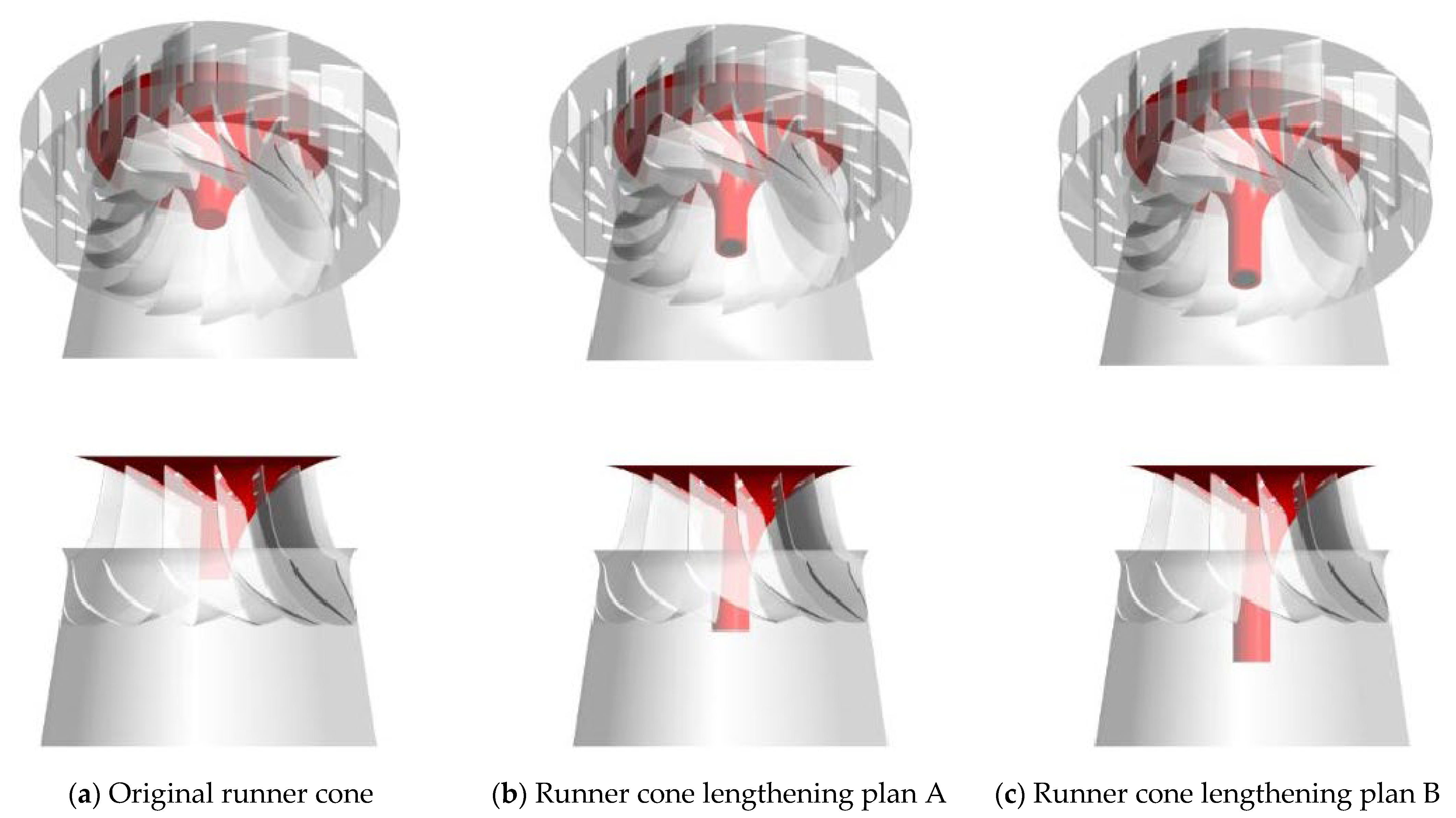
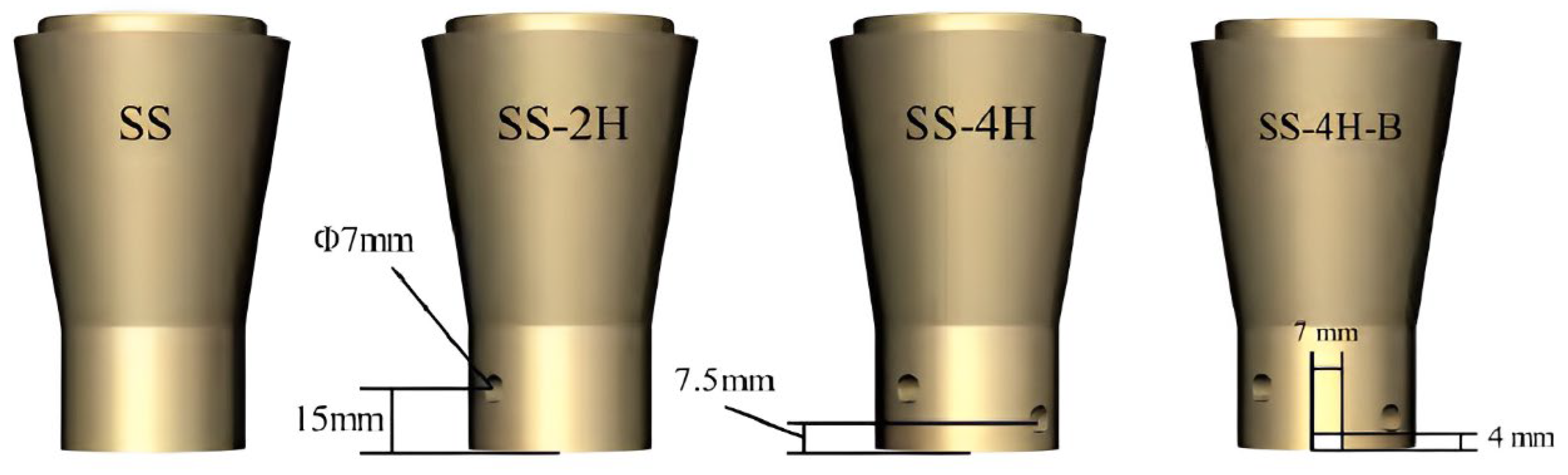
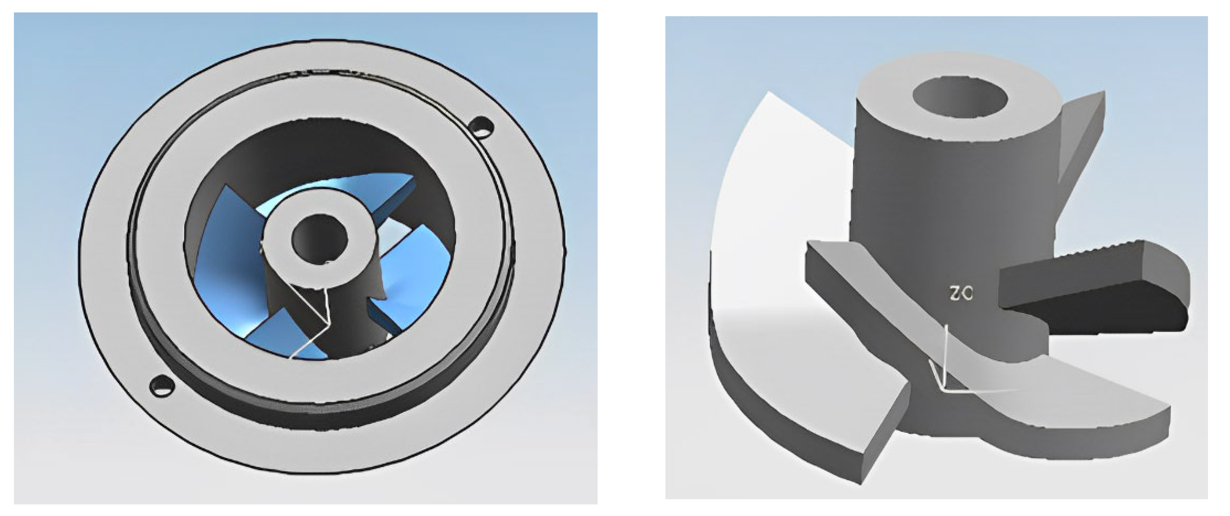
4.1.2. Structure Optimization of Runner Cone

The runner cones are located at the inlet of the draft tube. The structure of the runner cone greatly affects the flow state after the fluid enters the draft tube [66]. By optimizing the structure of the runner cone, the vortex rope and pressure pulse distribution in the draft tube can also be effectively suppressed. Vekve [67] carried out a lot of work on the runner cone extension; with the runner outlet diameter as the reference length, the runner cone extension can effectively reduce the pressure pulse around the draft tube inlet, and the extension of the outlet cone made the vortex rupture further downstream, compressed the development space in the vortex rope in the draft tube, and reduced the strength of the vortex structure. Gao et al. [65] also studied the length of the runner cone. The design scheme of the discharge cone is shown in Figure 15. It was found that the vortex rope in the draft tube decreased, but the eccentric distance of the vortex rope increased under some negative load conditions [68,69,70]. When the unit was running using the same runner, the axial non-eccentric vortex rope with approximate cones appeared in the center of the straight cone section of the draft tube. After the runner was lengthened, the formed vortex rope moved downward with the structural change, and the interference of the vortex rope to the fluid in the runner was reduced. The cavity vortex rope in the straight cone section gradually disappeared, which could not cause a disturbance to the water flow in the draft tube. Scholars have installed fin in the runner cone [71,72,73], the velocity distribution of the draft tube, and the velocity distribution of the flow field greatly affect the formation of the vortex rope and pressure pulsation; the change in the runner cone shape not only leads to the change in the vortex rope formation position but also changes the amplitude of the pressure pulsation in the draft tube.
The discharge cone is usually installed in the axial direction to mix the fluid [47,74]; compared with the simple cone, the discharge cone with the spiral groove has a better inhibition effect on the pressure pulse caused by the vortex rope. Under high spiral current conditions, the velocity around the runner cone increases with the increase in the radius of the spiral groove, which reduces the tangential velocity and pressure fluctuation amplitude, and the hydraulic loss and backflow in the draft tube can be neglected. Figure 16 shows the two runner cones [46]. Yu [73] optimized the design of the spiral groove on the runner cone and set the vortex suppression groove structure opposite to the vortex flow on the runner cone, as shown in Figure 17. The study showed that the vortex suppression groove structure could effectively reduce the diameter and length of the vortex trip, improve the pressure level in the low-pressure area, and the vortex suppression groove could also reduce the circular velocity of the inlet of the tail pipe, thus reducing the vortex flow strength, reducing the eccentric distance of the vortex trip, and playing a role in the vortex suppression. After introducing the vortex suppression trough, scholars found that the amplitude of the pressure pulsation at the monitoring point decreased significantly [75], the pressure average value increased slightly, and the vortex suppression trough significantly improved the lowest pressure value of the monitoring point, and partially reduced the highest-pressure value. The fast Fourier transform of the time-domain map shows that the vortex suppression groove can effectively reduce the amplitude of the pressure pulsation by more than 35% but has little effect on the frequency.
To study the influence of the runner cone punching and groove on vortex rope morphology and the pressure pulse under typical working conditions, Zhang Nan et al. [74] punched and slotted the runner cone, as shown in Figure 18. Under four kinds of runner cone conditions, the vortex rope’s overall shape was roughly the same, a complete spiral ribbon, but with the improvement in the number of holes, the vortex rope appeared broken and disorderly at the beginning; after the development of a certain length of complete ribbon, the slotting process to some extent could weaken the impact of the initial position of the vortex rope, but could not completely offset. The drilling of the runner cone increased the pressure pulse amplitude of the prototype runner cone in the draft tube; the amplitude of the pressure pulsation also increased slightly with double holes compared to large double holes, but the amplitude of the pressure pulsation was reduced when grooving on the basis of drilling.

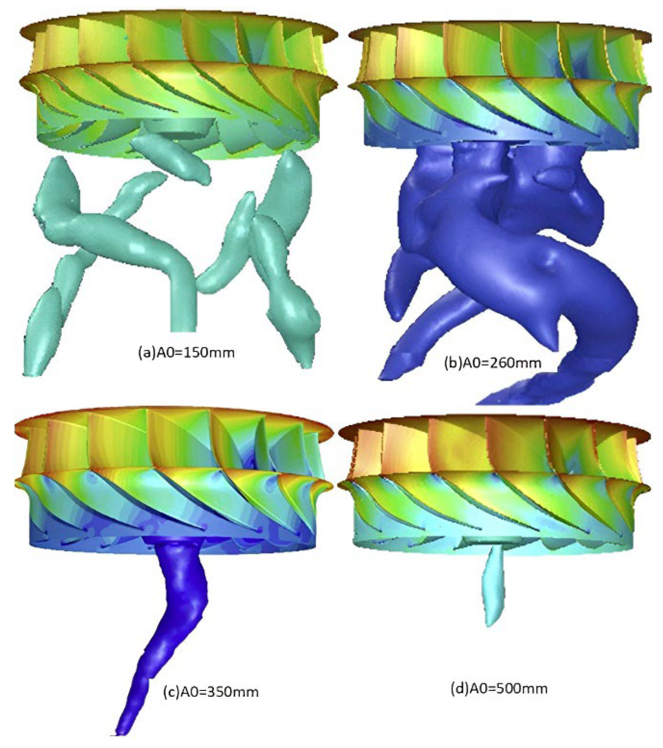
4.1.3. Guide Vane Opening

Minakov [48] conducted the three-dimensional unsteady constant numerical simulation of two different high-head French turbine turbines and conducted simulation calculations of the different guide vane openings, and found that the opening of the guide vane had a certain influence on the formation of the vortex rope. As shown in Figure 19, when the vane opening is relatively small, the vortex trip does not form an obvious shape but some small vortex wires. As the vane opening increases, the vortex trip shape begins to appear, and the vortex trip begins to become smaller [49].
The pressure pulsation is different in the tail pipe under various guide leaf openings [51,52]. When the opening is 40%, there is an irregular main negative pressure area in the central area of the tail pipe section, which is due to the fluid outflow through the runner outlet when the tail pipe wall is thrown out, resulting in a low-pressure cavity on the reference cross-section after fluid diversion. With the increase in the leaf opening, the irregular main negative pressure area at the eccentric area of the reference section occupies major parts of the section. Due to the low pressure in the main negative pressure area and the high pressure at the edge, the cavitation vortex rope may generate in the center area of the tail pipe, which is easy to cause serious cavitation erosion in the draft tube under the long-term action. The main negative pressure area is directly in contact with the wall of the tail pipe, which leads to a more serious pressure pulsation in the tail pipe. With the increase in the guide vane opening, the pressure pulsation at the elbow tube is more obvious than that in the inlet cone tube, indicating that the influence domain of the vortex rope moves downstream with the increase in the flow rate. By controlling the opening of the guide vane, the low-pressure area and the movement of the vortex rope in the draft tube can be controlled effectively, and the influence of the pressure pulsation generated by the vortex rope on the stable operation of the hydro turbine unit can be suppressed. Reasonable control of the guide vane opening can reduce hydraulic vibration and hydraulic loss in the draft tube.

4.2. Active Flow Control

Under a low flow or specific load, there are obvious vortex ropes and severe pressure pulsations in the draft tube of the turbine. These poor flow phenomena may lead to the stable operation of the turbine. Scholars actively replenish the fluid medium (air or water) into the draft tube to control the vortex rope. It can suppress the generation of the vortex in the draft tube and the pressure fluctuations.

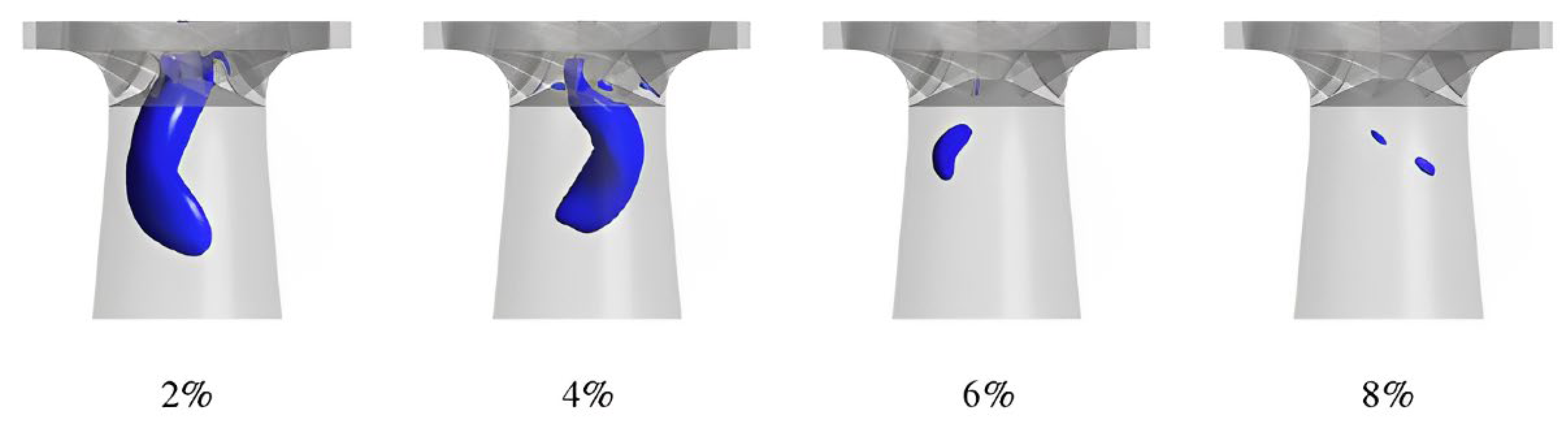
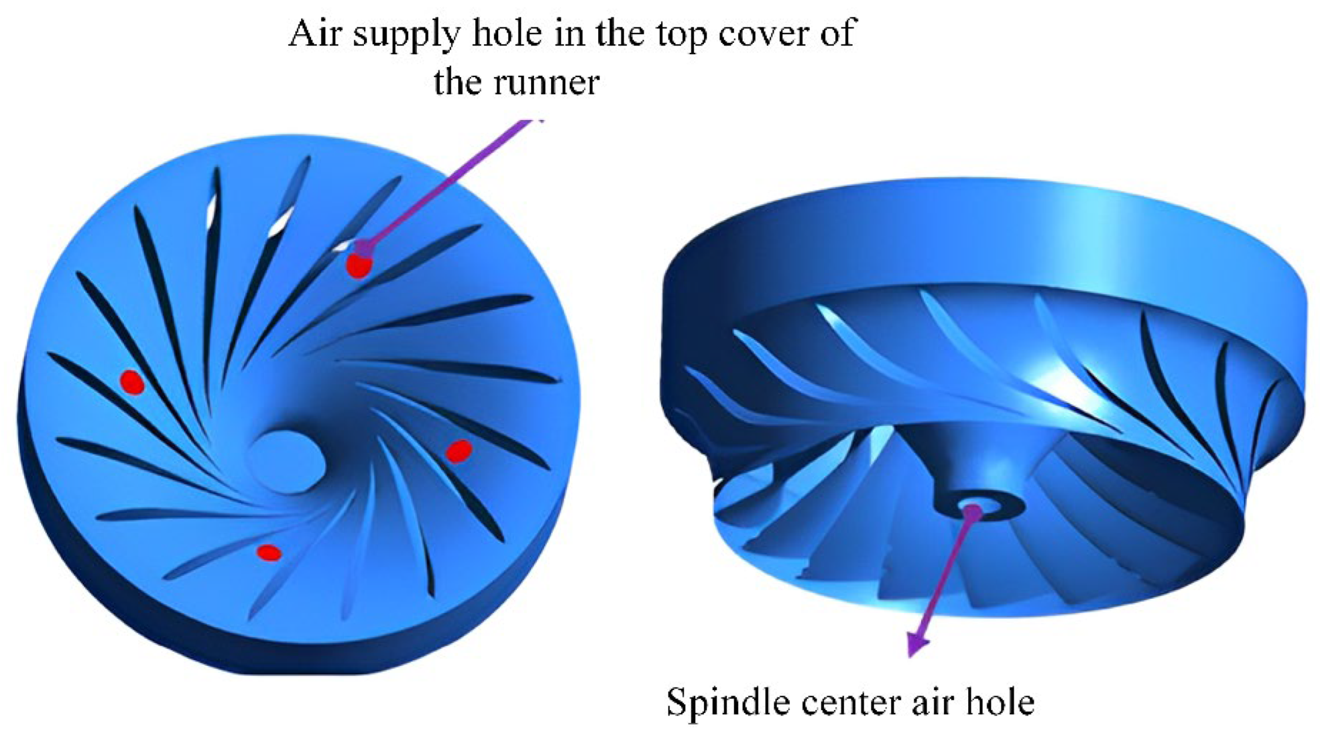
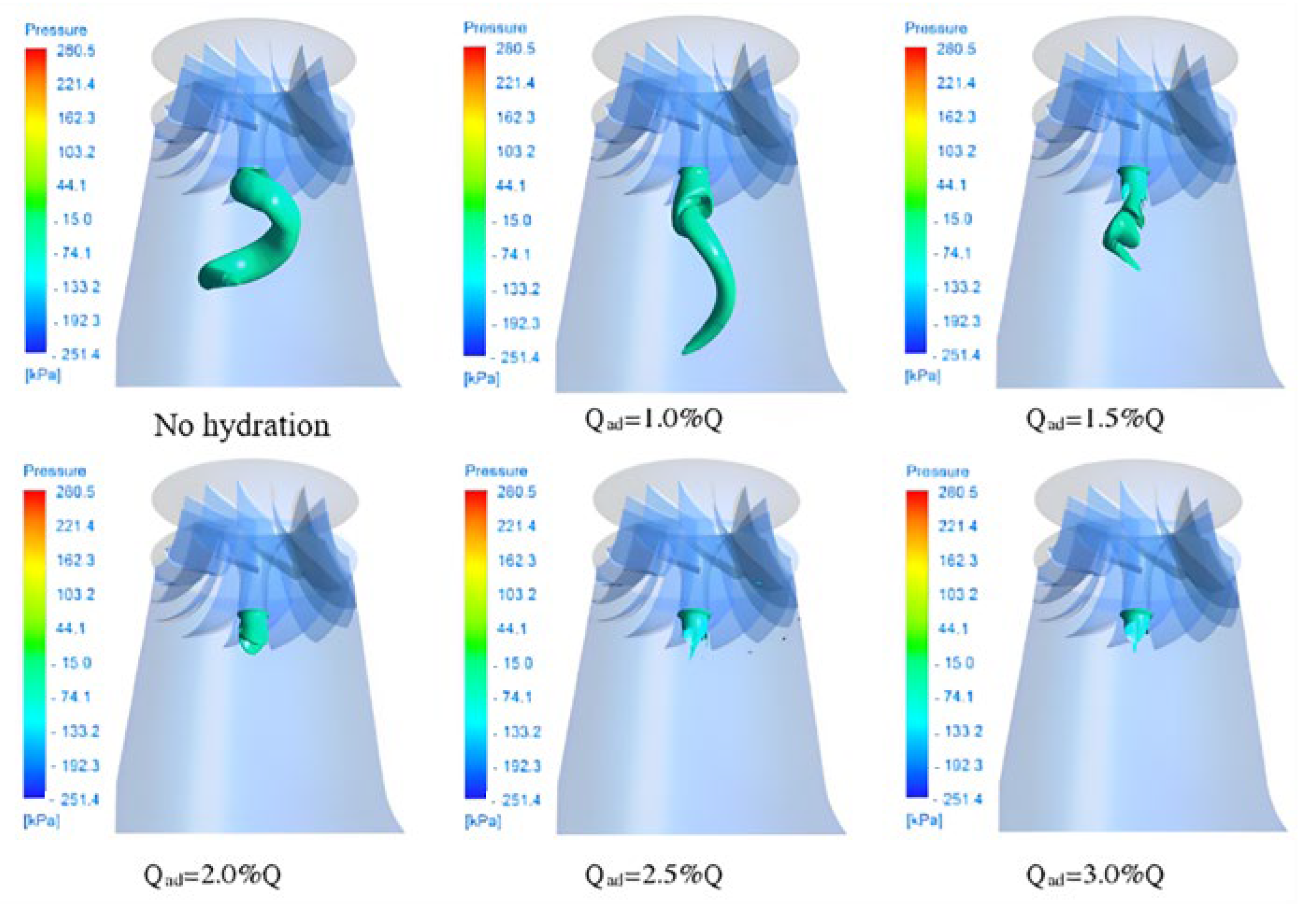
4.2.1. Replenish Air

Some scholars have found that spraying air into the draft tube of the turbine can effectively suppress high-frequency noise, power fluctuation, and vibration [76,77,78]. The schematic diagram of spraying air is shown in Figure 20. In addition to suppressing noise and vibration, the jet air also eliminates pressure pulsations, reduces cavitation effects on the flow path by buffering the shock, and avoids further vortex rope development. The reasonable selection of the amount of supplemental air is an important factor in inhibiting the occurrence of cavitation in the turbine. Studies have shown that only when the amount of supplemental air exceeds a critical value can it inhibit the occurrence of cavitation and effectively reduce the pressure pulsation induced by cavitation. However, excessive air supply not only consumes more external energy but also causes excessive disturbance to the main flow in the turbine, which may adversely deteriorate the hydraulic performance of the turbine. The amount of supplemental air has an important influence on the vortex movement and pressure pulsation in the draft tube. Haruki Murakami [76] found that when the intake air volume in the draft tube cone was 2–3%, the pressure recovery increased, and the pressure amplitude decreased; when the intake air volume was lower than 1.3%, the pressure pulsation and vibration increased. It reduced vibration and pressure pulsation by above 3%. Chen Along [77] used the main shaft center hole for air supply in the draft tube. When the air supply amount was small, the pressure pulsation caused by the vortex rotation disturbance could be suppressed, but the suppression effect on the pressure pulsation induced by cavitation was not obvious. There was no obvious improvement with the increase in the amount of supplemental gas: the improvement effect on the vortex rope was gradually highlighted, the vortex rope became shorter, the twist degree was larger, and the pressure pulsation was suppressed [79]. When the gas supplementation amount was large, the vortex band in the draft tube almost disappeared, leaving only a very small cavitation area; all pressure pulsations were suppressed, and the flow became relatively stable, as shown in Figure 21. Through analysis, the reason for the change in the vortex shape may be due to the decrease in the rotational speed and the decrease in the velocity circulation in the same direction of the draft tube inlet and the runner rotation, and then the vortex intensity generated in the draft tube was weakened. In the case of the partial load, the air supply to the draft tube could effectively reduce the amplitude of the pressure pulsation and change the pressure pulsation of the draft tube, but it could not change the frequency of the pressure pulsation [80]. Nakanishi et al. [81] found that when the best efficiency point was 80%, the flow rate of the supplemental gas was about 2% of the liquid flow rate, and the supplemental gas displaced the liquid phase flow in the draft tube and reduced the vortex flow. Although the eccentricity of the belt and the supplemental gas could not reduce the vorticity change rate, it could optimize the distribution of the vorticity change rate, thereby playing the role of vortex suppression [82]. The air supply can be injected from different positions [53,54]. At present, the widely used method of vapor injection, in addition to the spindle center hole vapor injection, also includes the runner cover vapor injection, especially in the natural vapor injection method and mainly the runner cover vapor injection. Yu [73] conducted research on two air supply methods, the air supply methods are shown in Figure 22. The results show that, compared with the main shaft center hole air supply, the runner top cover air supply can more effectively reduce the pressure pulsation and amplitude and the vortex suppression. The influence of the nuclear pressure level and eccentricity was greater, and the vortex suppression ability was stronger. Different air supply positions had different effects on hydraulic efficiency. The top cover air supply can improve the hydraulic efficiency of the turbine, while the air supply through the central hole of the main shaft reduces the hydraulic efficiency of the turbine, but the effects are relatively small, within 1% [73].

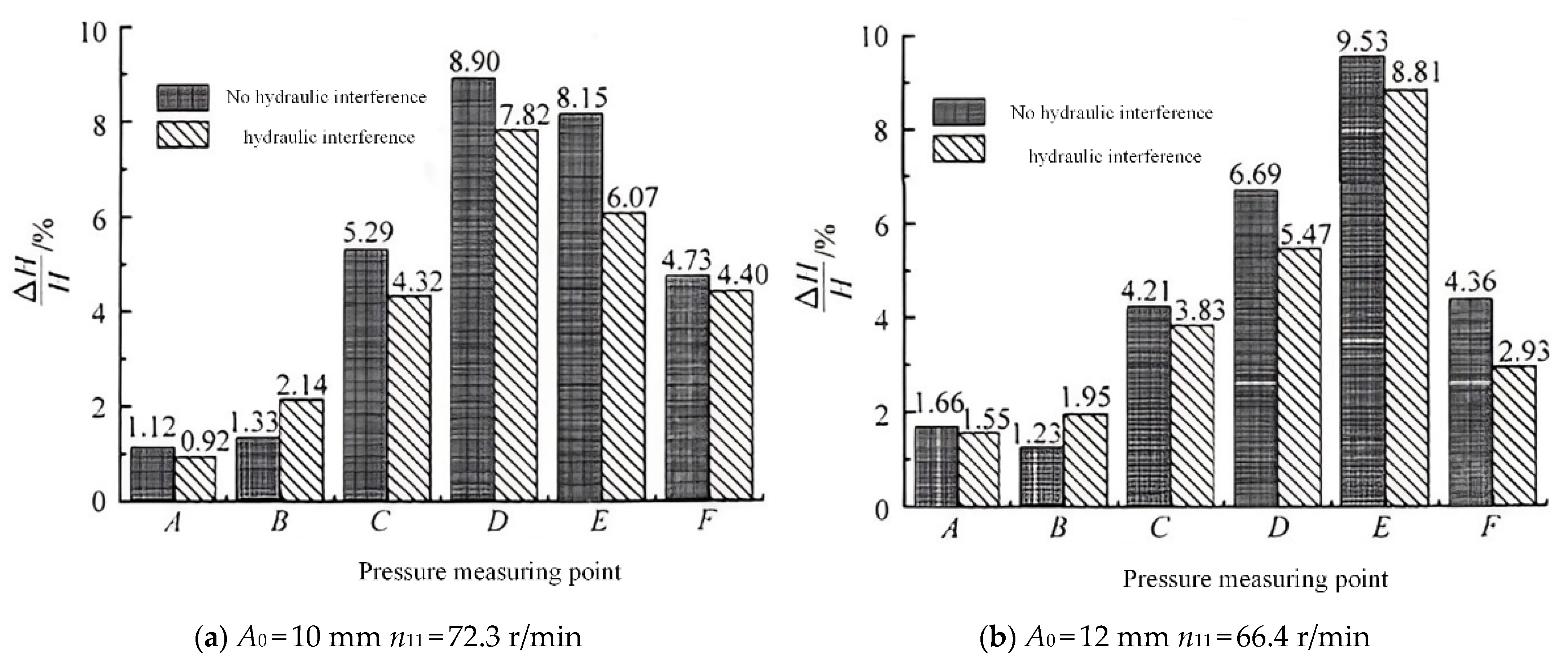
4.2.2. Water Injection

Water injection is also used to suppress the vortex and pressure pulsation in the draft tube, and water injection is usually divided into two categories: tangential water injection and axial water injection [83]. The nozzle for tangential water injection is installed on the wall of the draft tube, and the angle of the nozzle can be adjusted. The tangential water injection in the opposite direction of the eddy current can effectively reduce the amplitude of the pressure pulsation but also reduce the overall efficiency of the turbine. Negative circulation replenishment is similar to tangential replenishment. It also replenishes water in the opposite direction of the eddy current. This requires a special drain cone to achieve the water injection effect. The drain cone and its internal structure are shown in Figure 23 [84]. Li [38] found that 3% Q negative circulation water injection can effectively reduce the pressure pulsation amplitude in the draft tube. As shown in Figure 24, the experiment selected the guide vane opening A0 of 10 mm and 12 mm, respectively, and the speed n11 of 72.3 r/min and 64 r/min, respectively, to study the influence on the pressure pulsation characteristics.
Compared with tangential water injection, axial water injection should be more in engineering [80], and the axial water injection pipeline is shown in Figure 25. Under partial load conditions, with the increase in the draft tube pressure recovery, both draft tube flow and flow channel flow are improved with minimal loss of efficiency. The dominant frequency of the vortex rope can be eliminated by axial water injection, the amplitude of the pressure pulsation can be reduced, and the amplitude of the pressure pulsation decreases with the increase in the jet flow [85]. Hosein [86] effectively eliminated stagnant zones in the draft tube at 91% and 70% of the best efficiency point (BEP) flow rate using an axial make-up method, which improved the draft tube performance and reduced hydraulic losses. At a BEP flow of 91%, the loss factor was reduced by 50%, and at a BEP flow of 70%, the loss factor was reduced by 14%. Comparing the water injection amount and flow velocity, it can be found that the low-speed and high-flow water jet injection was more effective in suppressing the formation of the vortex and the pressure pulsation amplitude than the high-speed and small-flow water jet injection, and the downward movement of the stagnant region of the vortex was the main reason for the reduction in the pressure pulsation amplitude [87].
Draft tube pressure pulsations, noise, and structural vibrations can be effectively mitigated by fluid mitigation methods that either alter the frequency of the vortex or suppress its formation entirely. Figure 26 shows the variation trend of the draft tube vortex with different make-up amounts under partial load conditions. When the water injection is 1.0% Q, the volume of the vortex is reduced to a certain extent, and the eccentricity of the vortex core is relatively reduced, but the eccentric vortex of the draft tube is not completely eliminated. The eccentric vortex is basically eliminated, and there is no obvious draft tube vortex under the discharge cone; only the volume of the clearance cavity formed by the replenished water flow and the original draft tube water flow remains [88,89,90]. At 2.0% Q, the eccentric vortex of the draft tube is largely eliminated, and a good water injection effect is achieved [65]. The axial makeup water is often injected into the draft tube from the discharge cone. With the increase in the injected water, the flow in the center of the draft tube gradually tends to the direction of the mainstream, the flow-blocking effect becomes smaller, and the blocking area moves downstream. The low-frequency pressure pulsation in the draft tube can be improved by injecting a certain flow of water into the drain cone [91,92]. The pressure pulsation is shown in Figure 27. When the water with a flow rate of 0.03 Q is injected into the drain cone, the pressure pulsation in the straight cone section of the draft tube is reduced. When the flow rate is increased to 0.05 Q, the water jet can effectively reduce the pressure pulsation in the draft tube; when the water jet flow rate reaches 0.10 Q, the pressure pulsation amplitude becomes smaller [53].
The two hydraulic interference methods, axial water injection, and negative circulation water injection can effectively reduce the pressure pulsation of the Francis turbine. However, the jet can only reduce the twist of the vortex but cannot significantly reduce the volume of the vortex. With the increase in the water jet, the efficiency of the turbine decreases monotonically, and there is no trend of efficiency improvement. The improvement of the vortex rope and the optimization of the operating efficiency of the turbines are relatively poor, and the air supply method can be applied more in engineering. Further, the optimal parameters of the air injection under various operating conditions can be determined using intelligent optimization algorithms [93,94].

5. Conclusions

During the long-term operation of the turbine units, the vortex generated in the draft tube of the turbine causes the turbine to move away from the optimal working point and enters a partial load condition, reducing the stability and operating life of the turbine unit. A lot of research has been conducted on the harm and suppression methods of the vortex rope in the draft tube, and the main findings can be summarized as follows:
(1)
Under partial load conditions, the spiral belt in the draft tube revolves around the dead water area, which hinders the recovery of kinetic energy and leads to a decrease in the efficiency of the unit. Under the influence of periodic non-equilibrium factors, the volute strikes the wall of the draft tube, causing pressure pulsation in the draft tube and the unit to vibrate, which may lead to an accident in the turbine unit. The huge negative pressure generated by the worm belt forms cavitation, aggravates the axial vibration of the turbine, causes wall wear and damage, and even leads to serious consequences such as weld cracking.
(2)
Passive flow control often passively controls the flow field velocity and pressure distribution in the draft tube by changing the geometry of the main flow components of the turbine. Adding fins to the draft tube inlet cone can effectively inhibit the growth of the cavitation vortex and reduce the volume of the cavitation. The baffle of the inlet cone reduces the peripheral velocity entering the draft tube, making the flow more stable. Increasing the diffusion angle of the draft tube or setting up isolation piers can effectively suppress the development of the vortex and the amplitude of the pressure pulsation. The extended drain cone compresses the development space of the vortex in the draft tube, thereby reducing the vortex strength of the vortex. Designing a groove structure or adding fins on the drain cone can reduce the eccentricity of the vortex rope, and the pressure pulsation amplitude can be significantly reduced. The holes and slots on the drain cone and the opening of the guide vane can all play a role in eddy suppression and vibration reduction to a certain extent.
(3)
Active flow control can actively change the velocity and pressure distribution of the flow field inside the turbine draft tube by injecting media into the turbine flow field. Commonly used media are air and water. Air supplementation can effectively suppress high-frequency noise and pressure pulsation, as well as the generation of vortex ropes and cavitation. Nevertheless, under partial load conditions, the amount of supplemental air is an important factor for vortex suppression. Only when the amount of supplemental air reaches a certain value can a better effect be achieved. When the amount of supplemental gas is excessive, it worsens the performance of the turbine. The optimal amount of supplemental gas is usually about 2% of the liquid flow rate. Water injection is mainly divided into tangential replenishment and axial replenishment. Water injection can effectively reduce the volume and pressure amplitude of the vortex. However, with the increase in the amount of water injection, the efficiency of the turbine decreases monotonically. Compared with the air supply method, the water supply is relatively poor for the improvement of the vortex rope and the optimization of the operation efficiency of the turbine.
The study of vortex suppression is often carried out under abnormal conditions. The change in the controlled flow control method for the structure may affect the stable operation of other working conditions. The active control flow methods require additional systems to cooperate with the turbine unit, which is relatively complicated. At the same time, cavitation will occur in the turbine. Now, how to analyze the vortex suppression effect and practicability of the turbine from multiple dimensions still has a long way to go. The vortex suppression methods summarized by the existing research institutes can play a certain role, but they do not achieve the best results. Therefore, combined with the actual working conditions, it is the primary problem to select the appropriate vortex suppression method to effectively suppress the vortex and pressure pulsation, improve the stability of the turbine unit, and prolong the service life of the turbine unit.

Author Contributions

Conceptualization, L.W. and J.C.; methodology, L.W., L.S. and D.J.; validation, P.Z., J.C., and C.X.; formal analysis, J.C. and L.L.; writing—original draft preparation, J.C.; writing—review and editing, L.W., J.C. and L.L.; supervision, L.W. and C.X. All authors have read and agreed to the published version of the manuscript.

Funding

The authors gratefully acknowledge the financial supports given by the Key R&D Program of Zhejiang (No. 2022C02035), the Welfare Technology Applied Research Project of Zhejiang Province (No. LGG21E090003), and the National Nature Science Foundation of China (No. 51909195).

Data Availability Statement

Not applicable.

Conflicts of Interest

There is no conflicts of interest.

References

  1. Capik, M.; Yılmaz, A.O.; Cavusoglu, I. Hydropower for sustainable energy development in Turkey: The small hydropower case of the Eastern Black Sea Region. Renew. Sustain. Energy Rev. 2012, 16, 6160–6172. [Google Scholar] [CrossRef]
  2. Blair, T. Energy Production Systems Engineering; IEEE Press: Piscataway, NJ, USA, 2016. [Google Scholar]
  3. Mei, Z.Y. Mechanical Design and Manufacture of Hydraulic Machinery; Routledge: New York, NY, USA, 2018. [Google Scholar]
  4. Xu, Y.; Qin, D.; Zhao, Y.; Wang, H. Exploratory analysis on pressure fluctuation conversion in Francis turbine draft tubes. J. Hydroelectr. Eng. 2016, 01, 87–94. (In Chinese) [Google Scholar]
  5. Zhou, P.; Dai, J.; Yan, C.; Zheng, S.; Ye, C.; Zhang, X. Effect of Stall Cells on Pressure Fluctuations Characteristics in a Centrifugal Pump. Symmetry 2019, 11, 1116. [Google Scholar] [CrossRef] [Green Version]
  6. Liu, X.; Luo, Y.; Wang, Z. A review on fatigue damage mechanism in hydro turbines. Renew. Sustain. Energy Rev. 2016, 54, 1–14. [Google Scholar] [CrossRef]
  7. Zuo, Z.; Liu, S.; De-Min, L.; Da-Qing, Q. Numeical analyses of pressure fluctuations induced by interblade vortex in a model Francis turbine. J. Hydrodyn. Ser. B 2015, 27, 513–521. [Google Scholar] [CrossRef]
  8. Paik, J.; Sotiropoulos, F.; Sale, M.J. Numerical simulation of swirling flow in complex hydro turbine draft tube using unsteady statistical turbulence models. J. Hydraul. Eng. 2005, 131, 441–456. [Google Scholar] [CrossRef]
  9. Sandeep, K.; Cervantes Michel, J.; Gandhi Bhupendra, K. Rotating vortex rope formation and mitigation in draft tube of hydro turbines—A review from experimental perspective. Renew. Sustain. Energy Rev. 2021, 136. [Google Scholar]
  10. Goyal, R.; Cervantes, M.J.; Gandhi, B.K. Vortex rope formation in a high head model Francis turbine. J. Fluids Eng. 2017, 139. [Google Scholar] [CrossRef]
  11. Ruprecht, A.; Helmrich, T.; Aschenbrenner, T.; Scherer, T. Simulation of vortex rope in a turbine draft tube. In Proceedings of the 21st IAHR Symposium on Hydraulic Machinery and Systems. EPFL/STI/LMH, Lausanne, Switzerland, 9–12 September 2002; Volume 1, pp. 259–266. [Google Scholar]
  12. Hellström, J.; Marjavaara, B.; Lundström, T. Parallel CFD simulations of an original and redesigned hydraulic turbine draft tube. Adv. Eng. Softw. 2007, 38, 338–344. [Google Scholar] [CrossRef]
  13. Zuo, Z.; Liu, S.; Sun, Y.; Wu, Y. Pressure fluctuations in the vaneless space of High-head pump-turbines—A review. Renew. Sustain. Energy Rev. 2015, 41, 965–974. [Google Scholar] [CrossRef]
  14. Yamamoto, K. Hydrodynamics of Francis Turbine Operation at Deep Part Load Condition; EPFL: Vaud, Switzerland, 2017. [Google Scholar]
  15. Subodh, K.; Singh Krishna, M.; Cervantes Michel, J.; Gandhi Bhupendra, K. Numerical analysis of water jet injection in the draft tube of a Francis turbine at part load operations. J. Fluids Eng. 2022, 144. [Google Scholar]
  16. Iliescu, M.S.; Ciocan, G.D.; Avellan, F. Analysis of the cavitating draft tube vortex in a Francis turbine using particle image velocimetry measurements in two-phase flow. J. Fluids Eng. 2008, 130. [Google Scholar] [CrossRef]
  17. Qian, Z.; Yang, J.-D.; Huai, W.-X. Numerical Simulation and Analysis of Pressure Pulsation in Francis Hydraulic Turbine with Air Admission. J. Hydrodyn. 2007, 19, 467–472. [Google Scholar] [CrossRef]
  18. Pasche, S. Dynamics and Optimal Control of Self-Sustained Instabilities in Laminar and Turbulent Swirling Flows: Application to the Part Load Vortex Rope in Francis Turbines; EPFL: Vaud, Switzerland, 2018. [Google Scholar]
  19. Laouari, A.; Ghenaiet, A. Investigation of steady and unsteady cavitating flows through a small Francis turbine. Renew. Energy 2021, 172, 841–861. [Google Scholar] [CrossRef]
  20. Yan, X. Study on Instability and Improvement Strategy of Draft Vortex of Mixed Flow Turbine; Harbin Institute of Technology: Harbin, China, 2019. (In Chinese) [Google Scholar]
  21. Juposhti, H.J.; Maddahian, R.; Cervantes, M.J. Optimization of axial water injection to mitigate the Rotating Vortex Rope in a Francis turbine. Renew. Energy 2021, 175, 214–231. [Google Scholar] [CrossRef]
  22. Gehrer, A.; Egger, A.; Riener, J. Numerical and Experimental Investigation of the Draft Tube Flow Downstream of a Blub Turbine; IAHR Symposium: Lausanne, Switzerland, 2002; p. 12. [Google Scholar]
  23. Rheingans, W.J. Power swings in hydroelectric power plants. Trans. ASME 1940, 62, 171–184. [Google Scholar]
  24. Nicolet, C.; Zobeiri, A.; Maruzewski, P.; Avellan, F. Experimental Investigations on Upper Part Load Vortex Rope Pressure Fluctuations in Francis Turbine Draft Tube. Int. J. Fluid Mach. Syst. 2011, 4, 179–190. [Google Scholar] [CrossRef] [Green Version]
  25. Nicolle, J.; Morissette, J.F.; Giroux, A.M. Transient CFD simulation of a Francis turbine startup. In Proceedings of the IOP Conference Series: Earth and Environmental Science, Beijing, China, 19–23 August 2012; Volume 15. [Google Scholar]
  26. Sotoudeh, N.; Maddahian, R.; Cervantes, M.J. Investigation of Rotating Vortex Rope formation during load variation in a Francis turbine draft tube. Renew. Energy 2019, 151, 238–254. [Google Scholar] [CrossRef]
  27. Siwani, Y.D. Dynamic Stress Assessment in High Head Francis Runners. 2008. Available online: https:www.mimbersbrunn.se/article?id=11498 (accessed on 4 December 2022).
  28. Nishi, M.; Kubota, T.; Matsunaga, S.; Senoo, Y. Study on swirl flow and surge in an elbow type draft tube. In Proceedings of the IAHR 10th Symposium, Tokyo, Japan, 1980; Volume 1, pp. 557–568. Available online: https://www.researchgate.net/publication/280886636_Study_on_Swirl_Flow_and_Surge_in_an_Elbow_Type_Draft_Tube (accessed on 25 October 2022).
  29. Koutnik, J.; Krüger, K.; Pochyly, F.; Rudolf, P.; Haban, V. On cavitating vortex rope form stability during Francis turbine part load operation. In Proceedings of the First Meeting of the IAHR Internationalss Working Group on Cavitation and Dynamic Problems in Hydraulic Machinery and Systems, Barcelona, Spain, 28–30 June 2006; p. 304. [Google Scholar]
  30. Jacob, T.; Prénat, J.E. Francis turbine surge: Discussion and data base. In Hydraulic Machinery and Cavitation; Springer: Dordrecht, The Netherlands, 1996; pp. 855–864. [Google Scholar]
  31. Shyy, W.; Braaten, M.E. Three-dimensional analysis of the flow in a curved hydraulic turbine draft tube. Int. J. Numer. Methods Fluids 1986, 6, 861–882. [Google Scholar] [CrossRef]
  32. Vu, T.C.; Shyy, W. Viscous Flow Analysis for Hydraulic Turbine Draft Tubes. In IAHR Symposium Trondheim; Trondheim, Norway, 1988. [Google Scholar]
  33. Wang, X.M.; Nishi, M.; Tsukamoto, H. A Simple Model for Predicting the Draft Tube Surge; Chan-guo, D., Schilling, R., Zu-yan, M., Eds.; X VII IAHR Symposiumium Beijing; International Rsearch Center on Hydraulic Machinery: Beijing, China, 1994; pp. 95–106. [Google Scholar]
  34. Wang, X.M.; Nishi, M. Swirling flow with helical vortex core in a draft tube predicted by a vortex method. In Hydraulic Machinery and Cavitation; Springer: Dordrecht, The Netherlands, 1996; pp. 965–974. [Google Scholar]
  35. Jin, G.; Sun, Z.; Zong, Z.; Zou, L.; Hu, Y. Conformal Mapping-Based Discrete Vortex Method for Simulating 2-D Flows around Arbitrary Cylinders. J. Mar. Sci. Eng. 2021, 9, 1409. [Google Scholar] [CrossRef]
  36. Li, Z.; Chang, J.; Xin, Z. Numerical Simulation of Elimination of Pressure Fluctuation in Francis Turbine Draft Tube Using Water Jet. Trans. Chin. Soc. Agric. Mach. 2013, 01, 53–57. (In Chinese) [Google Scholar]
  37. Ruprecht, A.; Maihöfer, M.; Heitele, M.; Helmrich, T. Massively parallel computation of the flow in hydro turbines. In Proceedings of the 21st IAHR Symposium on Hydraulic Machinery and Systems, Lausanne, Switzerland, 9–12 September 2002; pp. 199–206.A. [Google Scholar]
  38. Li, Z. Study on the Stability of Million kW Francis Turbine; China Agricultural University: Beijing, China, 2012. (In Chinese) [Google Scholar]
  39. Anup, K.C.; Lee, Y.H.; Thapa, B. CFD study on prediction of vortex shedding in draft tube of Francis turbine and vortex control techniques. Renew. Energy 2016, 86, 1406–1421. [Google Scholar]
  40. Song, H. Numerical Simulation of Internal Flow and Pressure Fluctuation Characteristics of Medium Head Mixed Flow Turbine; Xihua University: Chengdu, China, 2021. (In Chinese) [Google Scholar]
  41. Tian, Y. Numerical Simulation of Cavitation Flow in Waterwheel Tailpipe; China Agricultural University: Beijing, China, 2006. (In Chinese) [Google Scholar]
  42. Jingchun, W.; Katsumasa, S.; Kiyohito, T.; Kazuo, N.; Joushirou, S. CFD-Based Design Optimization for Hydro Turbines. J. Fluids Eng. 2007, 129, 159–168. [Google Scholar]
  43. Sano, T.; Ookawa, M.; Watanabe, H.; Okamoto, N.; Yano, H.; Fukuda, N.; Maekawa, M.; Miyagawa, K. A new methodology for suppressing pressure pulsation in a draft tube by grooved runner cone. Fluids Eng. Div. Summer Meet. 2011, 44403, 1943–1950. [Google Scholar]
  44. Gao, C. Numerical Analysis of Flow Field Improvement for Draft Tube of Francis Turbine; Xi’an University of Technology: Xi’an, China, 2019. (In Chinese) [Google Scholar]
  45. Xiaoqing, T.; Yuan, Z.; Huachen, P.; Bin, S. Numerical and Experimental Study on a Model Draft Tube with Vortex Generators. Adv. Mech. Eng. 2013, 5, 509314. [Google Scholar] [CrossRef] [Green Version]
  46. Marshall, J.S. The effect of axial pressure gradient on axisymmetrical and helical vortex waves. Phys. Fluids A Fluid Dyn. 1993, 5, 588–599. [Google Scholar] [CrossRef]
  47. Li, G.; Lu, C. Experimental Study on Draft Tube Vortex of Francis Turbine. Hydropower Pumped Storage 2019, 5, 52–57. [Google Scholar]
  48. Minakov, A.; Platonov, D.; Dekterev, A.; Sentyabov, A.; Zakharov, A. The analysis of unsteady flow structure and low frequency pressure pulsations in the high-head Francis turbines. Int. J. Heat Fluid Flow 2015, 53, 183–194. [Google Scholar] [CrossRef]
  49. Gogstad, P.J. Experimental Investigation and Mitigation of Pressure Pulsations in Francis Turbines; NTNU: Trondheim, Norway, 2017. [Google Scholar]
  50. He, W.; Wan, T.; Ma, T.; Lu, Z.; Ma, C. Analysis of the Influence of Air Supplement on the Vibration Characteristics of the Tailrace Vortex rope and Unit. Power Syst. Clean Energy 2021, 37, 101–106+115. (In Chinese) [Google Scholar]
  51. Silva, P.C.O.; Nicolet, C.; Grillot, P.; Drommi, J.-L.; Kawkabani, B. Assessment of power swings in hydropower plants through high-order modeling and eigenanalysis. IEEE Trans. Ind. Appl. 2017, 53, 3345–3354. [Google Scholar] [CrossRef]
  52. Dorfler, P.; Sick, M.; Coutu, A. Flow-Induced Pulsation and Vibration in Hydroelectric Machinery; Springer: London, UK, 2013. [Google Scholar]
  53. Li, Z.; Chang, J. Experiment of Mitigation of Low Frequency Pressure Fluctuation in Draft Tube by Axial Water Jet. Trans. Chin. Soc. Agric. Mach. 2013, 44, 45–49. [Google Scholar]
  54. Li, Z.; Chang, J.; Ji, X.; Liu, W. Hydraulic Disturbance Method to Reduce the Pressure Fluctuation in Francis Turbine Draft Tube. In Proceedings of the ASME-JSME-KSME Joint Fluids Engineering Conference, Hamamatsu, Japan, 24–29 July 2011. [Google Scholar]
  55. Lecher, W.; Baumann, K. Francis turbines at part-load with high back-pressure. In IAHR Section Hydraulic Machinery, Equipment, and Cavitation: 4th Symposium; Lausanne, Switzerland, 1968; p. 4. [Google Scholar]
  56. Müller, A.; Favrel, A.; Landry, C.; Avellan, F. Fluid–structure interaction mechanisms leading to dangerous power swings in Francis turbines at full load. J. Fluids Struct. 2017, 69, 56–71. [Google Scholar] [CrossRef]
  57. Rocha, G.; Sillos, A. Power swing produced by hydropower units. In Proceedings of the 11th IAHR Symposium on Hydraulic Machinery and Cavitation, Amsterdam, The Netherlands, 13–17 September 1982; p. 44. [Google Scholar]
  58. Thicke, R.H. Practical solutions for draft tube instability. Water Power Dam Constr. 1981, 33, 31–37. [Google Scholar]
  59. Doerfler, P.K. Observation of the pressure pulsation on Francis model turbine with high specific speed. Hydropower Dams 1994, 21–26. [Google Scholar]
  60. Skripkin, S.G.; Tsoy, M.A.; Kuibin, P.A.; Shtork, S.I. Study of pressure shock caused by a vortex ring separated from a vortex rope in a draft tube model. J. Fluids Eng. 2017, 139, 081103. [Google Scholar] [CrossRef]
  61. Wu, W.; Li, L.; Lv, R.; Yu, A. A Research on Pressure Pulsation Characteristics and Improvement Measures of Pump Turbine Draft Tube under Different Working Conditions. Hydropower Pumped Storage 2021, 7, 11–19. (In Chinese) [Google Scholar]
  62. Ruizhi, Z.; Daohong, X.; Xianwu, L. Influence of fins on draft tube wall on pressure fluctuation of Francis turbine. Acta Aerodyn. Sin. 2020, 38, 788–795. [Google Scholar]
  63. Zhu, H.Y.; Liu, Q.Y.; Wang, T. Reducing the bottom-hole differential pressure by vortex and hydraulic jet methods. J. Vibroengineering 2014, 16, 2224–2249. [Google Scholar]
  64. Arakawa, C.; Qian, Y.; Kubota, T. Turbulent Flow Simulation of a Runner for Francis Hydraulic Turbines Using Pseudo-Compressibility. J. Fluids Eng. 1996, 118, 285–291. [Google Scholar] [CrossRef]
  65. Zhao, D.; Gao, C.; Sun, W.; Guo, P.; Ma, W. Effect of runner cone length and shaft center hole water feeding on flow charac-teristics in draft tube. J. Drain. Irrig. Mach. Eng. (JDIME) 2019, 37, 413–419 + 434. [Google Scholar]
  66. Subodh, K.; Sandeep, K.; Singh Krishna, M.; Cervantes Michel, J.; Gandhi Bhupendra, K. Influence of the runner cone design on the pressure fluctuations in the draft tube of a low head Francis turbine. IOP Conf. Ser. Earth Environ.Sci. 2021, 774, 012110. [Google Scholar]
  67. Vekve, T. An Experimental Investigation of Draft Tube Flow; NTNU: Trondheim, Norway, 2004. [Google Scholar]
  68. Cheng, H.; Zhou, L.; Liang, Q.; Guan, Z.; Liu, D.; Wang, Z.; Kang, W. A method of evaluating the vortex rope strength in draft tube of Francis turbine. Renew. Energy 2020, 152, 770–780. [Google Scholar] [CrossRef]
  69. Nishi, M.; Wang, X.M.; Yoshida, K.; Takahashi, T.; Tsukamoto, T. An experimental study on fins, their role in control of the draft tube surging. In Hydraulic Machinery and Cavitation; Springer: Dordrecht, The Netherlands, 1996; pp. 905–914. [Google Scholar]
  70. Kuibin, P.; Susan-Resiga, R.F.; Muntean, S. A model for precessing helical vortex in the turbine discharge cone. IOP Conf. Series: Earth Environ. Sci. 2014, 22, 22024. [Google Scholar] [CrossRef] [Green Version]
  71. Kurokawa, J.; Imamura, H.; Choi, Y.-D. Effect of J-Groove on the Suppression of Swirl Flow in a Conical Diffuser. J. Fluids Eng. 2010, 132, 071101. [Google Scholar] [CrossRef]
  72. Sano, T.; Maekawa, M.; Okamoto, N.; Yano, H.; Miyagawa, K. Investigation of flow pattern downstream of spiral grooved runner cone in pump-turbine. IOP Conf. Ser. Earth Environ. Sci. 2012, 15, 022019. [Google Scholar] [CrossRef]
  73. Yu, A. Analysis of the Pressure Fluctuations and Vortical Flow Characteristics in a Francis Turbine Draft Tube with Air Admission; Tsinghua University: Beijing, China, 2017. [Google Scholar]
  74. Zhang, N. Study on Mechanism of the Development of the Cavitation Vortex Rope in the Francis Turbine; Harbin Institute of Technology: Harbin, China, 2020. (In Chinese) [Google Scholar]
  75. Owen, J.C.; Szewczyk, A.A.; Bearman, P.W. Suppression of Karman vortex shedding. Phys. Fluids 2000, 12, S9. [Google Scholar] [CrossRef] [Green Version]
  76. Murakami, M. Vibration of Water Turbine when Air is admitted to its Draft Tube: Experimental Study. Bull. JSME 1958, 1, 298–304. [Google Scholar] [CrossRef] [Green Version]
  77. Chen, A. Study on Characteristics and Improvement Methods of Draft Tube Vortex Rope in a Pump Turbine; Harbin Institute of Technology: Harbin, China, 2017. [Google Scholar]
  78. Casanova García, F.; Mantilla Viveros, C.A. Experimental Analysis of the Vibration on the Draft Tube of a Francis Hydraulic Turbine During Operation at Different Power Levels; Revista Facultad de Ingeniería Universidad de Antioquia: Medellin, Colombia, 2010; pp. 90–98. [Google Scholar]
  79. Doerfler, P. Design criteria for air admission systems in Francis turbines. In Proceedings of the 13th IAHR Symposiums, Montreal, QC, Canada, 1986; Volume 1, p. 8. Available online: https://www.researchgate.net/publication/273144219_Design_criteria_for_air_admission_systems_in_Francis_turbines (accessed on 25 October 2022).
  80. Pasche, S.; Avellan, F.; Gallaire, F. Part Load Vortex Rope as a Global Unstable Mode. J. Fluids Eng. 2017, 139, 051102. [Google Scholar] [CrossRef]
  81. Nakanishi, K.; Ueda, T. Air supply into draft tube of Francis turbine. Fuji Electr. Rev. 1964, 10, 81–91. [Google Scholar]
  82. Yongyan, N.; Renqing, Z.; Xiao, Z.; Zhongyong, P. Numerical investigation on radial impeller induced vortex rope in draft tube under partial load conditions. J. Mech. Sci. Technol. 2018, 32, 157–165. [Google Scholar]
  83. Geng, C.; Li, Y.; Tsujimoto, Y.; Nishi, M.; Luo, X. Pressure oscillations with ultra-low frequency induced by vortical flow inside Francis turbine draft tubes. Sustain. Energy Technol. Assessments 2021, 51, 101908. [Google Scholar] [CrossRef]
  84. Susan-Resiga, R.; Vu, T.C.; Muntean, S.; Ciocan, G.D.; Nennemann, B. Jet control of the draft tube vortex rope in Francis turbines at partial discharge. In Proceedings of the 23rd IAHR Symposium Conference, Ann Arbor, Michigan, 31 May–3 June 2006; pp. 67–80. [Google Scholar]
  85. Stefan, D.; Rudolf, P.; Muntean, S.; Susan-Resiga, R. Proper Orthogonal Decomposition of Self-Induced Instabilities in Decelerated Swirling Flows and Their Mitigation Through Axial Water Injection. J. Fluids Eng. 2017, 139, 081101. [Google Scholar] [CrossRef]
  86. Foroutan, H.; Yavuzkurt, S. An axisymmetric model for draft tube flow at partial load. J. Hydrodyn. 2016, 28, 195–205. [Google Scholar] [CrossRef]
  87. Kirschner, O.; Grupp, J.; Schmidt, H. Experimental Investigation of Vortex Control in a Simplified Straight Draft Tube Model; University of Stuttgart: Stuttgart, Germany, 2008. [Google Scholar]
  88. Zhang, H.; Zou, D.; Yang, X.; Mou, J.; Zhou, Q.; Xu, M. Liquid–Gas Jet Pump: A Review. Energies 2022, 15, 6978. [Google Scholar] [CrossRef]
  89. Luo, H.; Zhou, P.; Shu, L.; Mou, J.; Zheng, H.; Jiang, C.; Wang, Y. Energy Performance Curves Prediction of Centrifugal Pumps Based on Constrained PSO-SVR Model. Energies 2022, 15, 3309. [Google Scholar] [CrossRef]
  90. Huang, R.; Zhang, Z.; Zhang, W.; Mou, J.; Zhou, P.; Wang, Y. Energy performance prediction of the centrifugal pumps by using a hybrid neural network. Energy 2020, 213, 119005. [Google Scholar] [CrossRef]
  91. Sohn, S.-I.; Sakajo, T.; Kim, S.-C. Stability of barotropic vortex strip on a rotating sphere. Proc. R. Soc. A Math. Phys. Eng. Sci. 2018, 474, 20170883. [Google Scholar] [CrossRef] [Green Version]
  92. Zhang, T.; Hu, N.; Tan, X.; Lin, H.; Hu, H. Research on Internal Flow Characteristics of Pump-turbine in Turbine Plate under Different Guide Vane Openings. Hydropower Pumped Storage 2021, 7, 83–88. (In Chinese) [Google Scholar]
  93. Abraham, A.M.; Sadasivan, A.L. Optimization of a Draft Tube Design Using Surrogate Modelling and Genetic Algorithm. J. Inst. Eng. (India) Ser. C 2021, 102, 753–764. [Google Scholar] [CrossRef]
  94. Xu, M.; Zeng, G.; Wu, D.; Mou, J.; Zhao, J.; Zheng, S.; Huang, B.; Ren, Y. Structural Optimization of Jet Fish Pump Design Based on a Multi-Objective Genetic Algorithm. Energies 2022, 15, 4104. [Google Scholar] [CrossRef]
Figure 1. Number of published works every year obtained from Science Direct using the keyword: “vortex rope” (Accessed in December 2022).
Energies 15 09280 g001
Figure 2. Composition diagram of hydro turbine [14].
Energies 15 09280 g002
Figure 3. Schematic diagram of vortex rope evolution [18].
Energies 15 09280 g003
Figure 4. Schematic diagram of vortex motion in axial and radial sections in draft tube [19].
Energies 15 09280 g004
Figure 5. Vortex rope structure [20].
Energies 15 09280 g005
Figure 6. Typical pressure trend in a model Francis turbine draft tube cone [29].
Energies 15 09280 g006
Figure 7. Influence of turbulence model on draft tube vortex rope shape [39].
Energies 15 09280 g007
Figure 8. Frequency domain characteristics of pressure pulsation at monitoring points [40].
Energies 15 09280 g008
Figure 9. Pressure and velocity distribution of sections of the draft tube [40].
Energies 15 09280 g009
Figure 10. Installation position and size of diversion plate [62].
Energies 15 09280 g010
Figure 11. Volume change of hollow bubbles in draft tube [62].
Energies 15 09280 g011
Figure 12. Schematic diagram of diversion plate [61].
Energies 15 09280 g012
Figure 13. Velocity vectors of different sections of draft tube with diversion baffle scheme [61].
Energies 15 09280 g013
Figure 14. Installation of diversion plate at elbow [44].
Energies 15 09280 g014
Figure 15. Extension scheme of runner cone [44].
Energies 15 09280 g015
Figure 16. Physical drawing of runner cone [46].
Energies 15 09280 g016
Figure 17. Different structure forms of runner cone [74].
Energies 15 09280 g017
Figure 18. Structure drawing of different runner cone [74].
Energies 15 09280 g018
Figure 19. Under different guide vane opening, shape of draft tube vortex rope [48].
Energies 15 09280 g019
Figure 20. Schematic diagram of air injection [50].
Energies 15 09280 g020
Figure 21. The shape of the vortex rope under different air supply volumes [77].
Energies 15 09280 g021
Figure 22. Schematic diagram of the positions of different air supply holes [73].
Energies 15 09280 g022
Figure 23. Water injection drain cone [38].
Energies 15 09280 g023
Figure 24. Peak water injection pressure with 3% Q negative circulation [39].
Energies 15 09280 g024
Figure 25. Schematic diagram of the axial water jet structure [36].
Energies 15 09280 g025
Figure 26. Draft tube vortex rope in partial load condition [38].
Energies 15 09280 g026
Figure 27. Frequency domain characteristics of draft tube monitoring points [38].
Energies 15 09280 g027
Table 1. Methods of suppressing vortex and their advantages and disadvantages.
MethodClassificationAdvantagesDisadvantages
Passive Flow ControlStructure Optimization of Draft TubeStabilize the flow in the draft tube and reduce the pressure velocity and cavitation volume of the flow field [44].Little improvement in vortex stability in draft tube [45]
Structure Optimization of Draft TubeIncrease runner efficiency and effectively reduce pressure pulsation amplitude [46].The increase in the eccentricity of the vortex rope under partial negative load [47].
Guide Vane OpeningControl low pressure area in draft tube and movement of vortex rope to reduce hydraulic loss [48].Cavitation vortex generation, severe cavitation erosion over long periods [49].
Active Flow ControlReplenish AirEffectively suppress high frequency noise and pressure pulsation [50,51,52].Only to reach a certain value, to achieve better results [53].
Supplemental WaterEffectively improve the draft tube vortex shape, reduce the pressure pulse assignment [54].Causes the amount of water jest to increase and the turbine efficiency to decrease monotonously [53].
Publisher’s Note: MDPI stays neutral with regard to jurisdictional claims in published maps and institutional affiliations.

