Review

Single-Phase Fault Tolerant Multilevel Inverter Topologies—Comprehensive Review and Novel Comparative Factors

1
Department of Electrical Engineering, ZHCET, Aligarh Muslim University, Aligarh 202002, India
2
Department of Electrical and Computer Engineering, Florida International University, Miami, FL 33174, USA
3
Department of Electrical Engineering, College of Engineering, Jouf University, Sakaka 72341, Saudi Arabia
4
Queensland Micro and Nanotechnology Centre, Griffith University, Nathan, QLD 4111, Australia
5
Department of Electrical and Electronics Engineering, Yanbu Industrial College, Al Kulliyyah, Yanbu 46452, Saudi Arabia
*
Authors to whom correspondence should be addressed.
Energies 2022, 15(24), 9319; https://doi.org/10.3390/en15249319
Submission received: 25 September 2022 / Revised: 25 October 2022 / Accepted: 18 November 2022 / Published: 8 December 2022
(This article belongs to the Special Issue Integration of Power Electronics in Power Systems)

Abstract

:
Multilevel inverters (MLIs) are used in a variety of industrial applications in high- and medium-voltage systems. The modularity, high-power output from medium voltages, and low harmonic content are some of the advantages of MLIs. The reliability of MLIs is quite important. The reliability is affected by different kinds of faults occurring in the MLIs. In MLI circuits, switching devices are the most vulnerable components and have a major involvement in all types of faults. As an outcome, it is necessary to take proper corrective action in the event of a fault. This work provides a comprehensive review of different fault tolerant (FT) solutions for MLIs in the event of switch fault. Moreover, various single-phase FT MLI topologies are reviewed, along with their constructional features, merits, and demerits. This work also proposes a comparison approach that integrates novel factors to account for fault tolerance quantitatively. A comparison investigation verifies the effectiveness of the proposed method. The FT operation of an existing five-level FT MLI topology is discussed, simulated, and experimentally verified.

1. Introduction

Multilevel inverters are gaining importance in medium-voltage and high-power industrial applications [1,2]. The three MLI topologies, i.e., cascaded H-bridge (CHB), neutral point clamped (NPC), and flying capacitor (FC), are included in classical MLI topologies [3,4]. MLIs find applications in standalone or grid-connected PV systems [5,6,7,8], pumped storage power plants [9], active power filters [10,11], flexible AC transmission systems (FACTSs) [12], variable frequency drives [13], high-voltage DC (HVDC) system [14,15], etc.
Some of the merits of MLIs over two-level inverters have been discussed in the literature [1,2,16,17,18,19,20]. They include the following:
  • MLI provides a high-quality output voltage waveform with low harmonic content; hence, total harmonic distortion (THD) is reduced considerably.
  • Due to lower harmonic content, the need for low-frequency bulky filter requirement reduces, thereby reducing electromagnetic interference (EMI). Moreover, it has good electromagnetic compatibility (EMC).
  • MLI provides low voltage stress across switches. Hence, it enables users to generate high voltages by using low-rating semiconductor devices.
  • MLI can operate with both low frequency and a fundamental frequency modulation scheme satisfactorily. Switching losses are reduced in a low-frequency modulation scheme. Hence the efficiency of the inverter increases.
  • The reduction in overall inverter loss reduces the requirement for cooling arrangement.
  • MLI can provide FT operation under single- or multiple-switch faults.
Figure 1 depicts the fault distributions in power electronic converter components [21]. The semiconductor devices and capacitors are the most vulnerable components in MLIs. Significant failures in the semiconductor switching devices (insulated gate bipolar transistors (IGBTs) or metal oxide semiconductor field effect transistors (MOSFETs)) are open circuit (OC) faults and short circuit (SC) faults [22]. The causes of OC faults can be a loss of gating signals, thermal cycling, or the malfunctioning of gate driver circuits. The causes of SC faults can be high temperatures, avalanche stress, overvoltage, or incorrect gate voltage. The OC fault is not serious and hence does not cause damage to the system. On the other hand, the SC fault is critical and may cause severe damage to the system due to the high current flowing under faulty conditions [23]. Hence, it is recommended to remove the faulty device(s) as soon as a fault is detected in order to avoid fault propagation to other healthy switching devices. This is known as fault isolation.
As the number of voltage levels increases in conventional MLIs, the requirement for semiconductor switching devices increases. As a result, the FT operation is possible due to the presence of redundant switching states for generating the same voltage level. These redundant switches are utilized during a fault in the switch to ensure FT operation, thereby bypassing the faulty switching state [3]. The ability of an MLI to continue operation either with full or reduced power rating in case of component(s) failure is referred to as the fault tolerance of an MLI.
The conventional MLIs have the drawback of a higher number of components (semiconductor devices, DC sources, capacitors, and inductors) as the voltage level increases. Hence, MLIs result in higher costs and large sizes. Researchers are optimally reducing the active and passive components in MLIs to ensure cost reduction and modularity [1]. The focus to reduce semiconductor devices and other components as the number of level increases is reflected in “reduced device count (RDC) MLIs” was reviewed in [1,4,24,25,26,27].
In the case of switch faults in RDC MLIs, the healthy switches are utilized to generate the output voltage levels. The maximum number of voltage levels that can be generated in the case of a fault in switches depends on the available redundant states. Reducing the switches may lead to the loss of redundant states. Hence, there may be loss of output voltage level(s) [28,29]. The semiconductor switching device failure can lead to either complete shutdown of MLI or operation of MLI at reduced levels. The first option, i.e., complete shutdown of an MLI, may cause immeasurable economic and life losses in critical applications such as hospitals, electric vehicles, financial markets, military, PV systems, wind turbines, industries, etc. [30,31]. Low reliability is the limitation of RDC MLIs because of the loss of redundant switching states [28]. To overcome this limitation of RDC MLIs, FT MLIs are developed.
The FT MLI is one of the types of MLI that has an optimal number of switches and other components with the possibility of fault tolerance. FT MLI has the benefits of fault tolerance, as seen in conventional MLIs, and a smaller number of components, as seen in RDC MLIs [23]. The FT MLI would ensure the following [3]:
  • Tolerance to single and/or multiple OC and SC faults.
  • Uninterrupted power supply to the loads.
  • Satisfactory system efficiency.
  • Fewer switches and other components.
  • Lesser cost.
The optimal reduction of the switches and other components while preserving the output voltage levels and power in different switch faulty conditions is still a significant challenge. Several FT MLI topologies are proposed in the literature based on different FT techniques.
Figure 2 depicts the FT MLI operation in case of fault. It has four steps [22,32].
Fault diagnosis and fault tolerance are the two back-to-back processes in the FT MLI operation. The steps fault detection and fault identification come under fault diagnosis [22]. The algorithms based on fault diagnosis are reviewed in [33]. The steps fault isolation and fault reconfiguration come under fault tolerance [22]. Various fault isolation and fault reconfiguration techniques are reviewed in [30,33]. The primary goal of FT MLI operation is to avoid fault transmission and its catastrophic effects by detecting and diagnosing any type of malfunction early in order to avoid system shutdowns.
In the case of any fault, the fault detection is the first step. During this period, the fault alarm is activated, and the faulty component remains unknown. The second step is fault identification. This step helps in identifying the type (OC or SC fault) and location (which component of the MLI topology is faulty?) of the fault. The third step is fault isolation. During this period, the isolation of the faulty components takes place to avoid catastrophic failure of the healthy components and damage to the MLI. The last step is fault reconfiguration. During this period, reconfiguration of the MLI topology and/or modulation scheme takes place for uninterrupted power supply and safe operation [22]. The solutions used for MLI fault tolerance are known as MLI FT solutions.
Pre-fault is the period in which an MLI is working in normal (or healthy) conditions. During fault is the period in which the MLI may or may not work similarly to the normal condition due to the fault. Post-fault is the period in which the MLI is working after taking certain FT measures. FT MLI operation is necessary as a fault occurs to bring the MLI back in working condition.
In this paper, the authors review various recently developed single-phase FT MLI topologies. The features of the work include the following:
  • Classification of MLI FT solutions.
  • Review of single-phase FT MLI topologies with their constructional features, merits, and limitations.
  • Comparison of different single-phase FT MLI based on proposed novel factors.
  • Simulation and experimental verification of existing five-level FT MLI topology.

2. MLI FT Solutions

Different MLI FT solutions are presented in the literature. The classification is shown in Figure 3.
The MLI FT solutions can be classified into the following categories [22]:
  • Solution based on extra hardware components (EHC).
  • Solution based on no extra hardware components (NEHC).
  • Hybrid solutions.

2.1. MLI FT Solutions Based on EHC

In this MLI FT solution, the additional components (e.g., switching devices, power diodes, modules, relays, fuses, etc.) are added to the original MLI topology to continue supply by generating levels that are lost due to faulty switching device(s) [22]. In this solution, the process is mainly based on the use of extra hardware redundancy and FT control. The function of additional components is to add redundancy by providing conduction paths that are lost under faulty conditions in MLI topology. It also alters the modulation scheme to generate new switching angles. The MLI FT solutions based on extra hardware components can further be classified as follows [30]:
  • MLI FT solution based on switch(es) addition.
  • MLI FT solution based on leg addition.
  • MLI FT solution based on module replacement.
  • MLI FT solution based on parallel redundant inverter.

2.1.1. MLI FT Solution Based on Switch(es) Addition (SA)

In this MLI FT solution, the redundant switch(es) is added in the original MLI topology in order to provide redundant switching states. These redundant states generate voltage levels that are lost under faulty conditions. (a) The first solution is to add redundant switches, parallel or series, to the main switches. These solutions are reviewed in [30]. Higher switch count, higher conduction losses, and higher cost are the main drawbacks of the first solution. (b) The second solution is to add redundant switches in such a position that they can tolerate maximum faulty conditions. The merits of the second solution are less switches, lower cost, and single-switch fault tolerance. Reduced voltage levels and the inability to tolerate multiple-switch faults are the drawbacks of this second solution. The second solution is better than the first solution. Generally, this second solution is employed in those MLI topologies that cannot tolerate a few single-switch faults and result in a complete system shutdown. This second solution is investigated in [23,28].

2.1.2. MLI FT Solution Based on Leg Addition (LA)

In this MLI FT solution, a set of switches forming a leg (it is referred to as a redundant leg) is attached to the original MLI topology to generate redundant switching states. In case of any switch fault, these redundant paths are utilized to compensate for the lost voltage levels. Fault tolerance to single- and/or multiple-switch faults and the ability to preserve more voltage levels (as compared to the SA solution) are the merits of this solution. The main drawbacks of this solution include a greater number of switches, higher cost, and non-utilization of redundant switches under healthy conditions. This solution is reviewed in [30]. This solution is investigated in various recently developed single-phase FT MLIs [3,31,34,35] and three-phase FT MLIs [36].

2.1.3. MLI FT Solution Based on Module Replacement (MR)

This MLI FT solution is applicable to modular MLIs (MMLIs) and cascaded MLIs (CMLIs). In this solution, a faulted module is replaced with a healthy module (known as a redundant module) if a fault occurs in any module to allow for continuous power supply. The significant advantage of this solution is that it is easy to control. The major drawbacks are the higher cost and large size. This solution is reviewed in [30].

2.1.4. MLI FT Solution Based on Parallel Redundant Inverter (PRI)

This MLI FT solution is utilized in critical applications, i.e., in industries. In this solution, a similar inverter (referred to as a redundant inverter) is connected in parallel with the original inverter. This redundant inverter only works in the condition of complete failure of the original inverter. The merit of this solution is an uninterruptable power supply without causing economic losses. The drawbacks of this solution include the very high cost and greater space requirements. This solution is reviewed in [30].

2.2. MLI FT Solutions Based on NEHC

In this MLI FT solution, there is no need for extra hardware components to provide FT operation [22]. The MLI FT solutions free of additional components can further be classified as follows [22,30]:
  • MLI FT solution based on inherent hardware redundancy.
  • MLI FT solution based on module bypass.
  • MLI FT solution based on modulation scheme.

2.2.1. MLI FT Solution Based on Inherent Hardware Redundancy (IHR)

This MLI FT solution utilizes the inherent hardware redundancy of the original MLI topology without any need for additional switches. Such MLI topologies have redundant switching states for generating a particular voltage level. In the case of any switch fault, the MLI continues to deliver power through available healthy switches. The merits of this solution are 100% utilization of all switches under healthy conditions and no requirement for additional hardware components. The drawbacks of this solution include reduced voltage levels and the inability to tolerate some switch faults. This solution was investigated in various recently developed FT MLIs [31,37,38,39,40,41,42].

2.2.2. MLI FT Solution Based on Module Bypass (MB)

This MLI FT solution is applicable to MMLIs and CMLIs. In this solution, if a fault occurs in any module, the faulted module is bypassed, and the output power is supplied with the remaining healthy module(s). The merit of this solution includes no requirement for additional hardware components. The drawback of this solution is that it provides output power at reduced voltage levels. This solution is reviewed in [30].

2.2.3. MLI FT Solution Based on Modulation Scheme (MS)

This MLI FT solution is applicable in the case of three-phase MLIs. The three-phase MLI output results in an unbalanced output voltage due to a fault in one or more phases. Hence, it results in the complete shutdown of the MLI. However, a modulation-scheme-based MLI FT solution maintains a balanced output voltage by modifying the modulation strategy under post-fault conditions. Some of the modulation schemes utilized in this technique are phase-shift pulse width modulation (PS-PWM) and space-vector PWM. The FT operation of these modulation schemes is explained and reviewed in [30,33,43,44]. The merit of this solution includes no requirement for additional hardware components. The drawbacks of this solution include complex mathematical computations and output power at reduced voltage levels.

2.3. Hybrid Solutions

Hybrid solutions may either use additional components and MS solution, MB and MS solution, or miscellaneous methods to tolerate faults. Multiple fault tolerance and higher reliability are the merits of this solution. The drawbacks of this solution include reduced voltage levels under multiple faults and complex control. These solutions are investigated in [45,46,47].

3. Review of Single-Phase FT MLI Topologies

In this section, several single-phase FT MLIs, with their constructional features, merits, and limitations, are reviewed and compared based on proposed novel parameters. The topologies are named from TP1 to TP53.

3.1. Single-Phase FT MLIs

3.1.1. TP1 and TP2

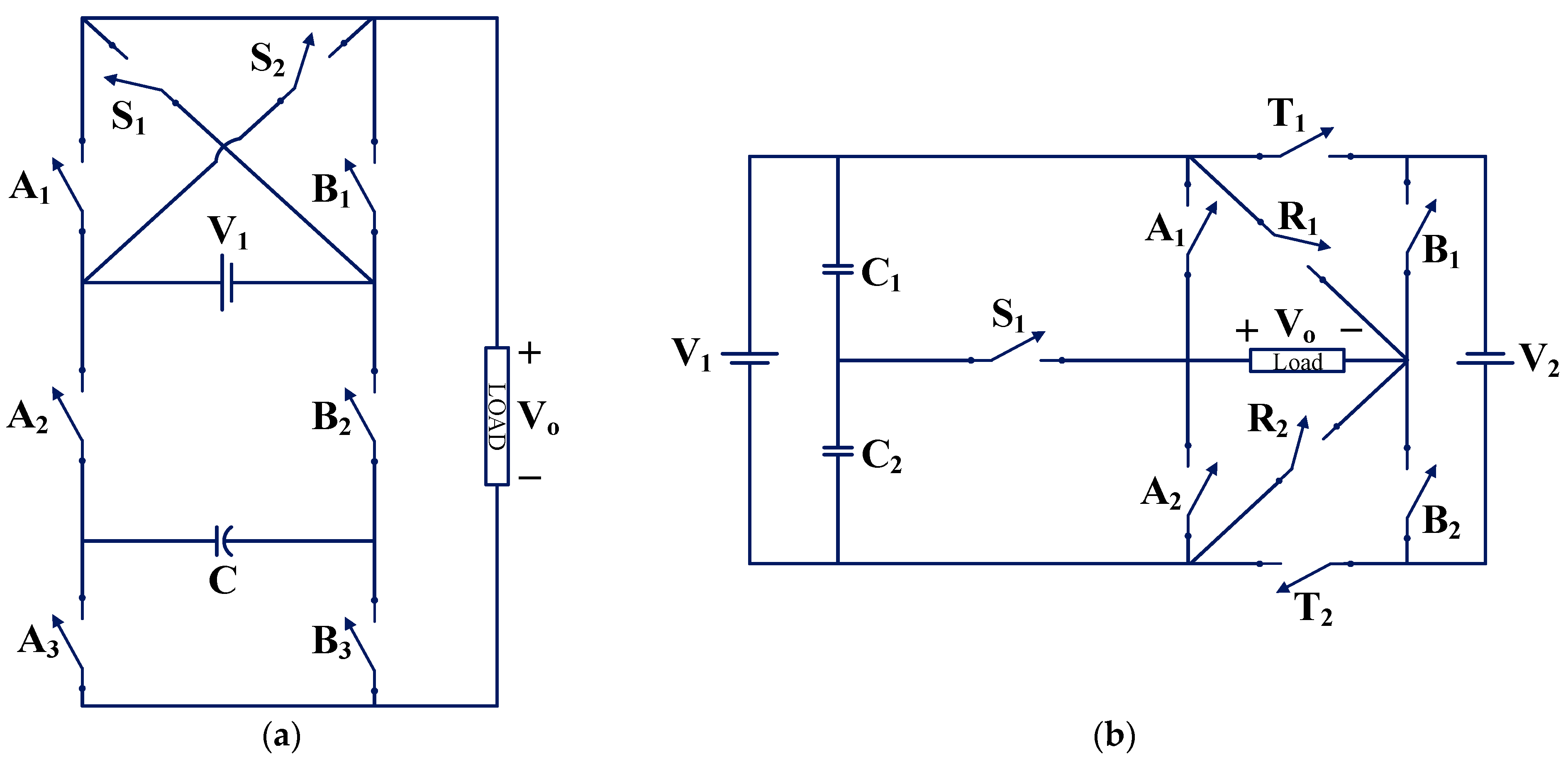
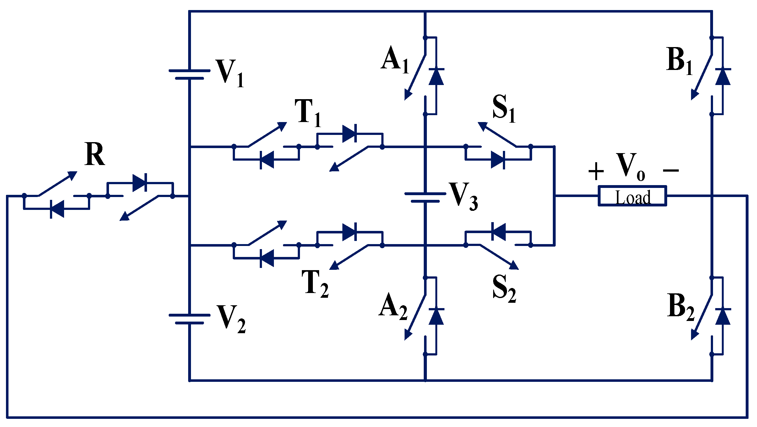
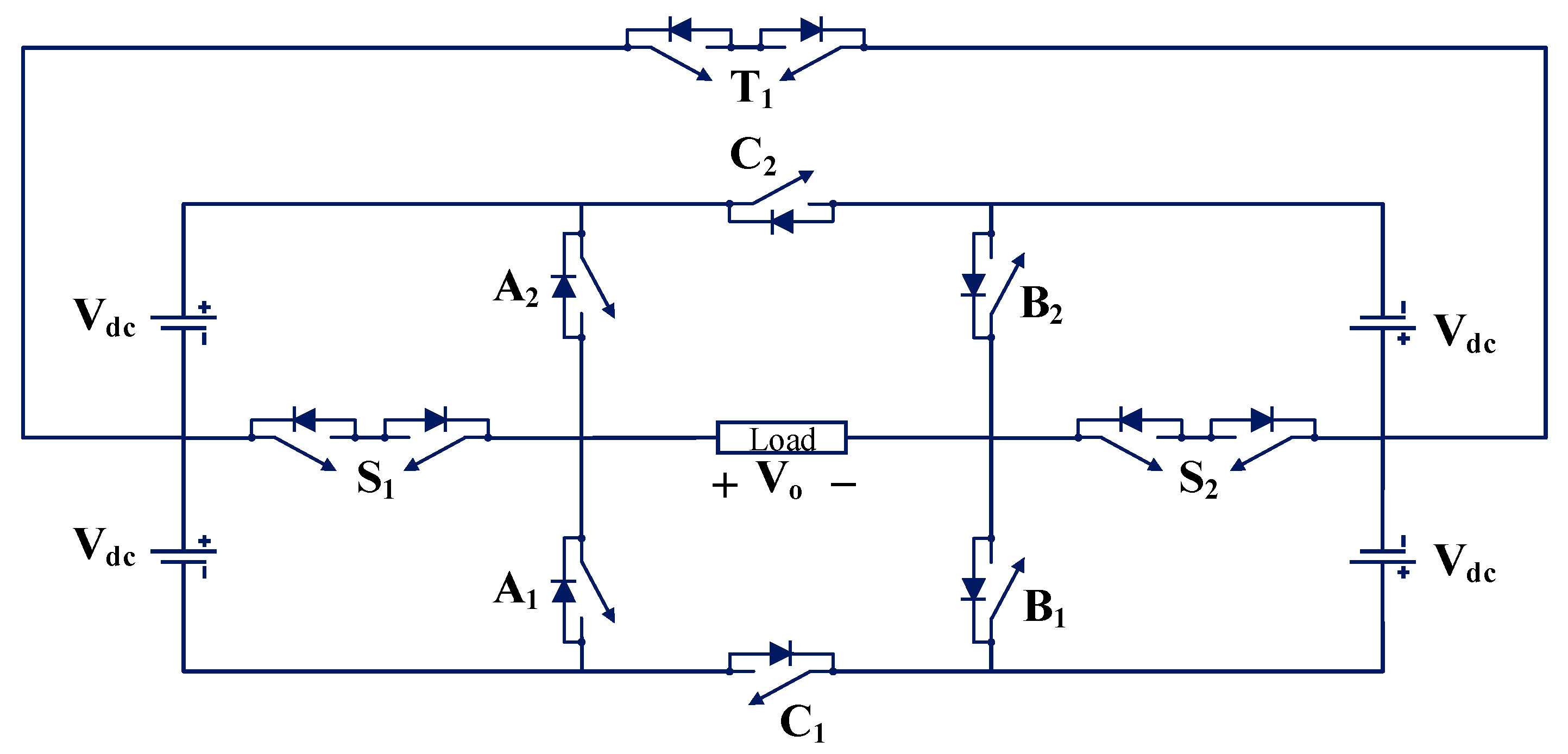
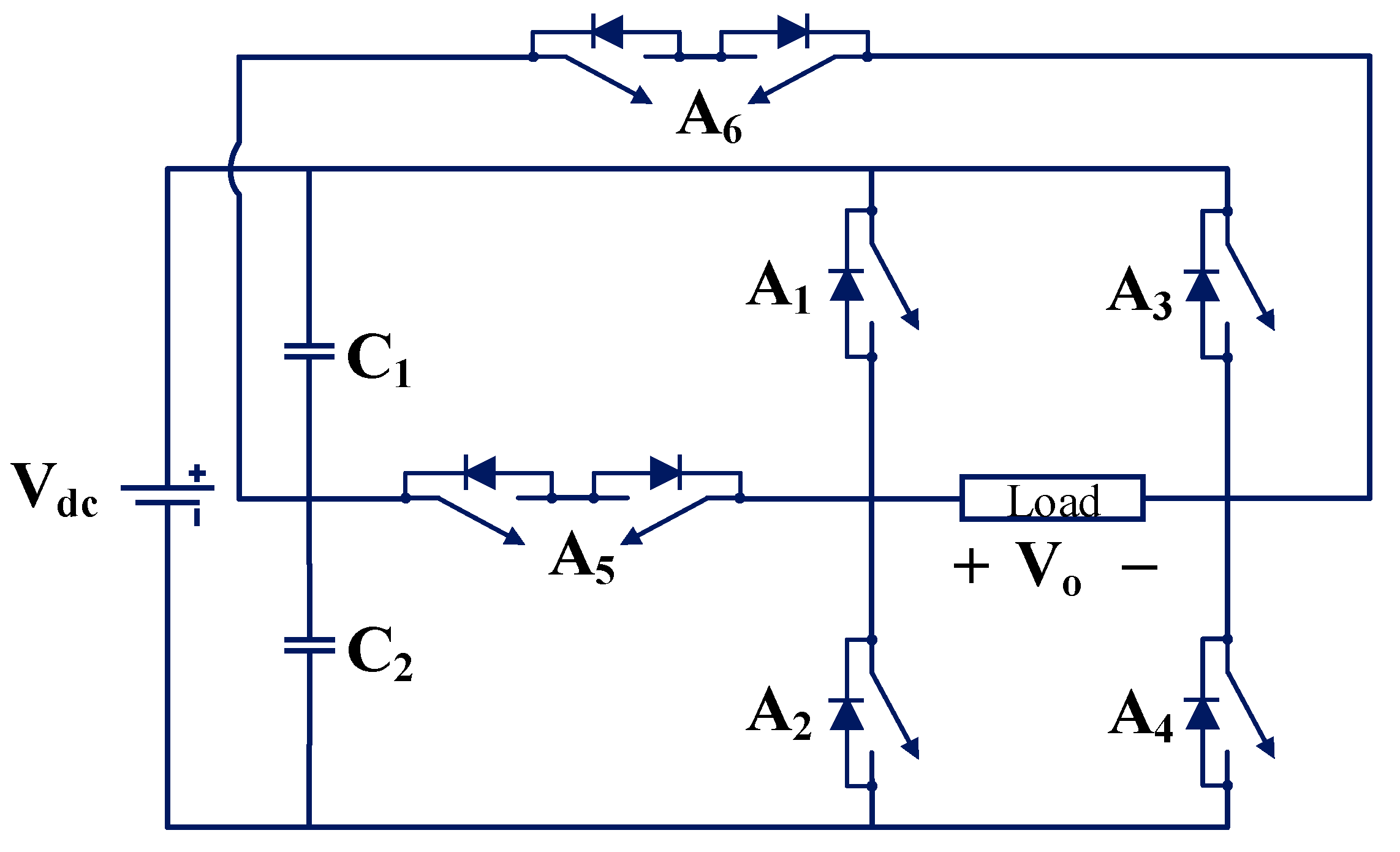
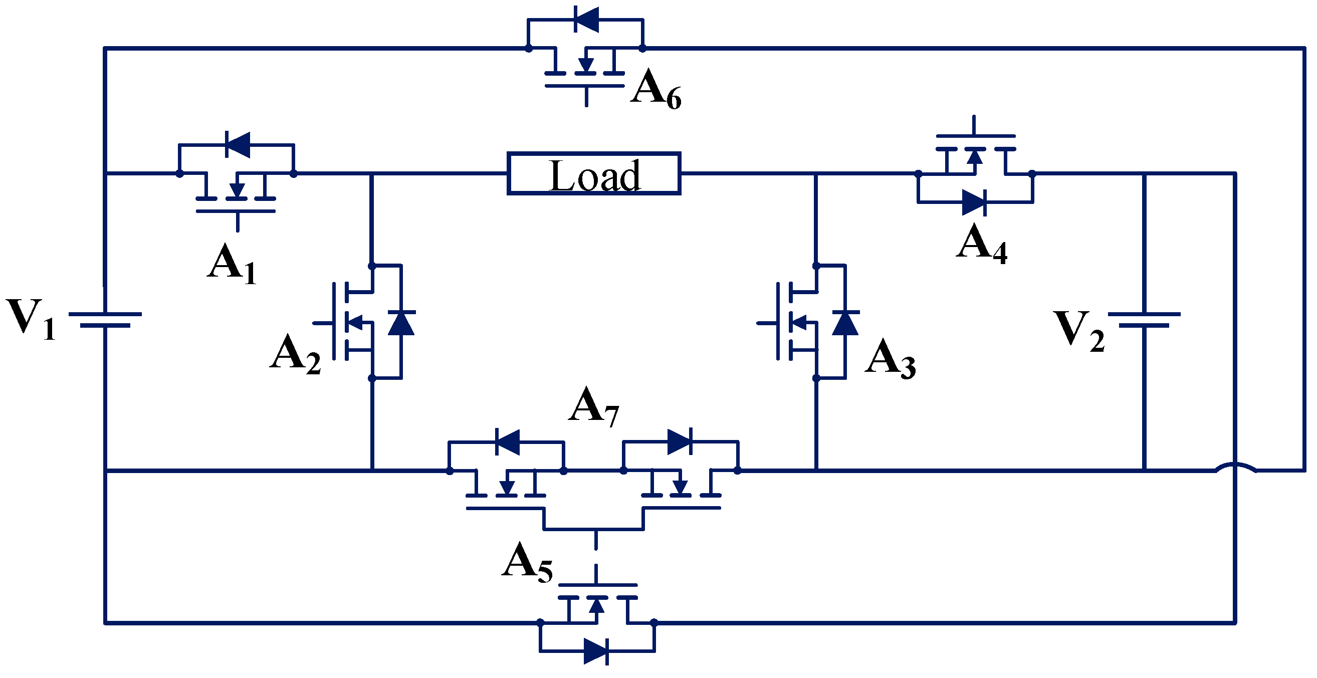
Other authors modified a cross-connected-sources-based MLI (CCS-MLI) and T-type MLI for FT operation in [28] by connecting switches S1 and S2, respectively. Both MLIs are single-phase five-level inverters. The circuit for FT CCS-MLI is shown in Figure 4a. The circuit for FT T-type MLI is shown in Figure 4b. A phase opposition disposition sinusoidal PWM (POD-SPWM) scheme is employed for generating switching pulses in both the topologies. Both the topologies use the SA FT solution for fault tolerance.
The topology TP1, i.e., modified CCS-MLI (as shown in Figure 4a), comprises two DC sources, one bidirectional switch (S1), and six unidirectional switches. It can generate only three levels for a single-switch OC fault in faulty conditions. This topology can tolerate a single-switch OC fault in the circuit with a loss of levels. A lower number of switches is the merit of the topology. The limitations of topology are the inability to tolerate multiple-switch faults and decreased output voltage levels under post-fault conditions.
The topology TP2, i.e., modified T-type inverter (as shown in Figure 4b), comprises two DC sources, two bidirectional switches (T1 and S2), and four unidirectional switches. It can generate three or five levels for a single-switch OC fault in faulty conditions. The topology can tolerate a single-switch OC fault in the circuit with a loss of levels. A lower number of switches is the merit of the topology. The limitations of topology are the inability to tolerate multiple-switch faults and decreased output voltage levels under post-fault conditions.

3.1.2. TP3 and TP4

Other authors modified a single-phase five-level Packed U-Cell MLI (PUC-MLI) and single-phase seven-level symmetrical and asymmetrical MLI topology for FT operation in [48] by connecting switches S1 and S2, and R1 and R2, respectively. The circuit for FT PUC-MLI (TP3) is shown in Figure 5a. The circuit for FT symmetrical and asymmetrical MLI (TP4) is shown in Figure 5b. A level-shifted SPWM (LS-SPWM) scheme is employed for generating switching pulses in both topologies. Both topologies use the SA FT solution for fault tolerance.
The topology TP3, i.e., modified PUC MLI (as shown in Figure 5a), comprises one DC source, one capacitor, and eight unidirectional switches. It can generate three or five levels for a single-switch OC fault in a faulty condition. This topology can tolerate a single-switch OC fault in the circuit with a loss of levels. A smaller number of switches is the merit of the topology. The limitations of topology are the inability to tolerate multiple-switch faults and decreased output voltage levels under post-fault conditions.
The topology TP4, i.e., modified symmetrical and asymmetrical MLI (as shown in Figure 5b), comprises two DC sources, two capacitors, three bidirectional switches, and six unidirectional switches. Switches (S1, R1, and R2) are bidirectional switches. It can generate five levels for a single-switch OC fault in a faulty condition. This topology can tolerate a single-switch OC fault in the circuit with a loss of levels. A smaller number of switches is the merit of the topology. The limitations of topology are the use of bidirectional switches, the inability to tolerate multiple-switch faults, and decreased output voltage levels under post-fault conditions.

3.1.3. TP5

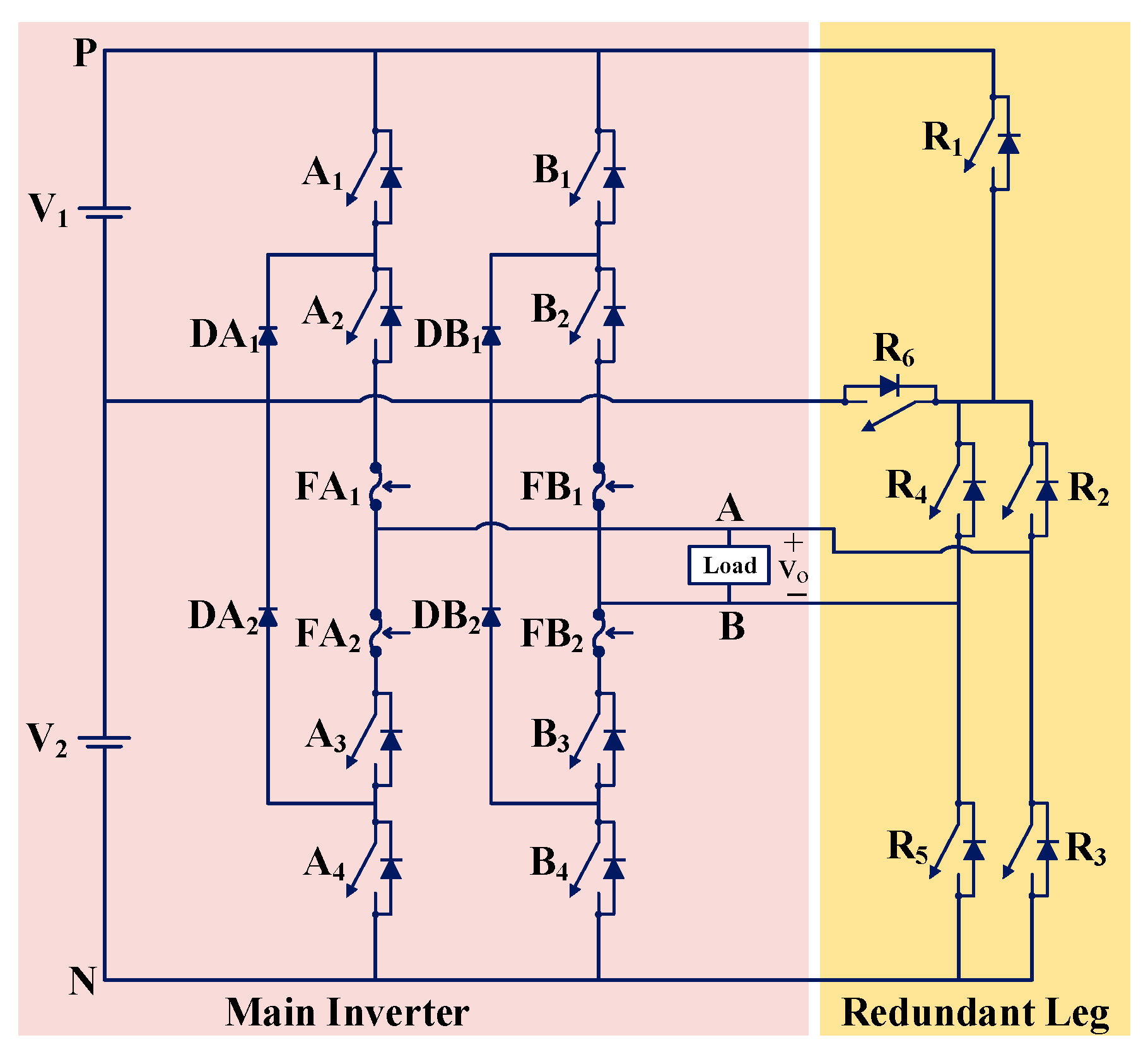
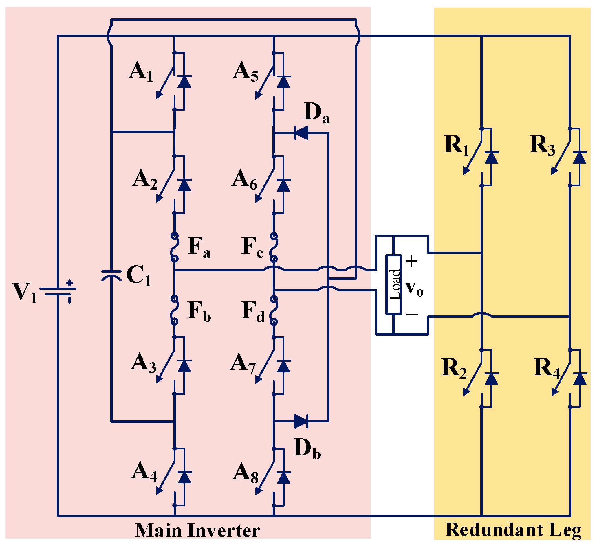
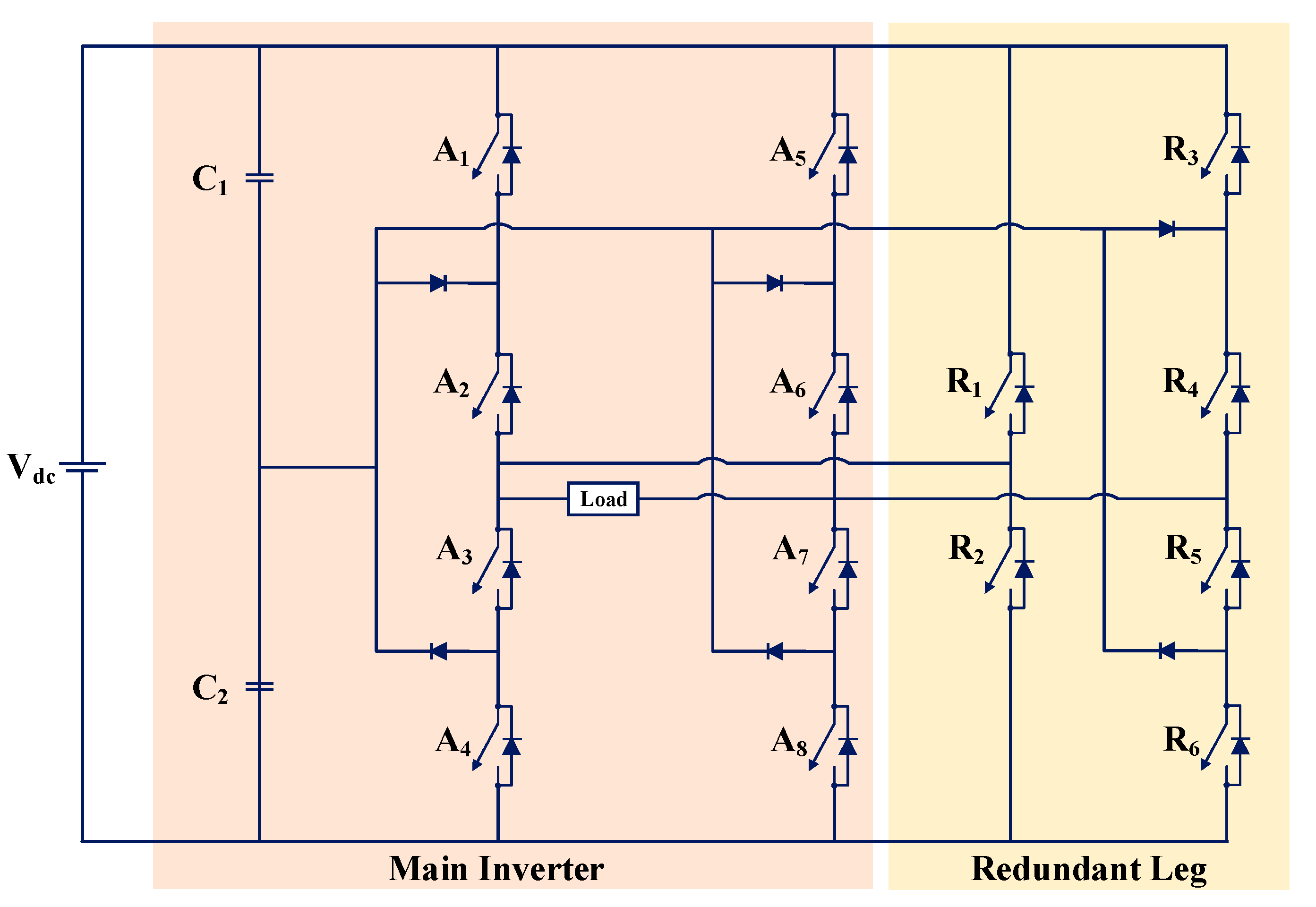
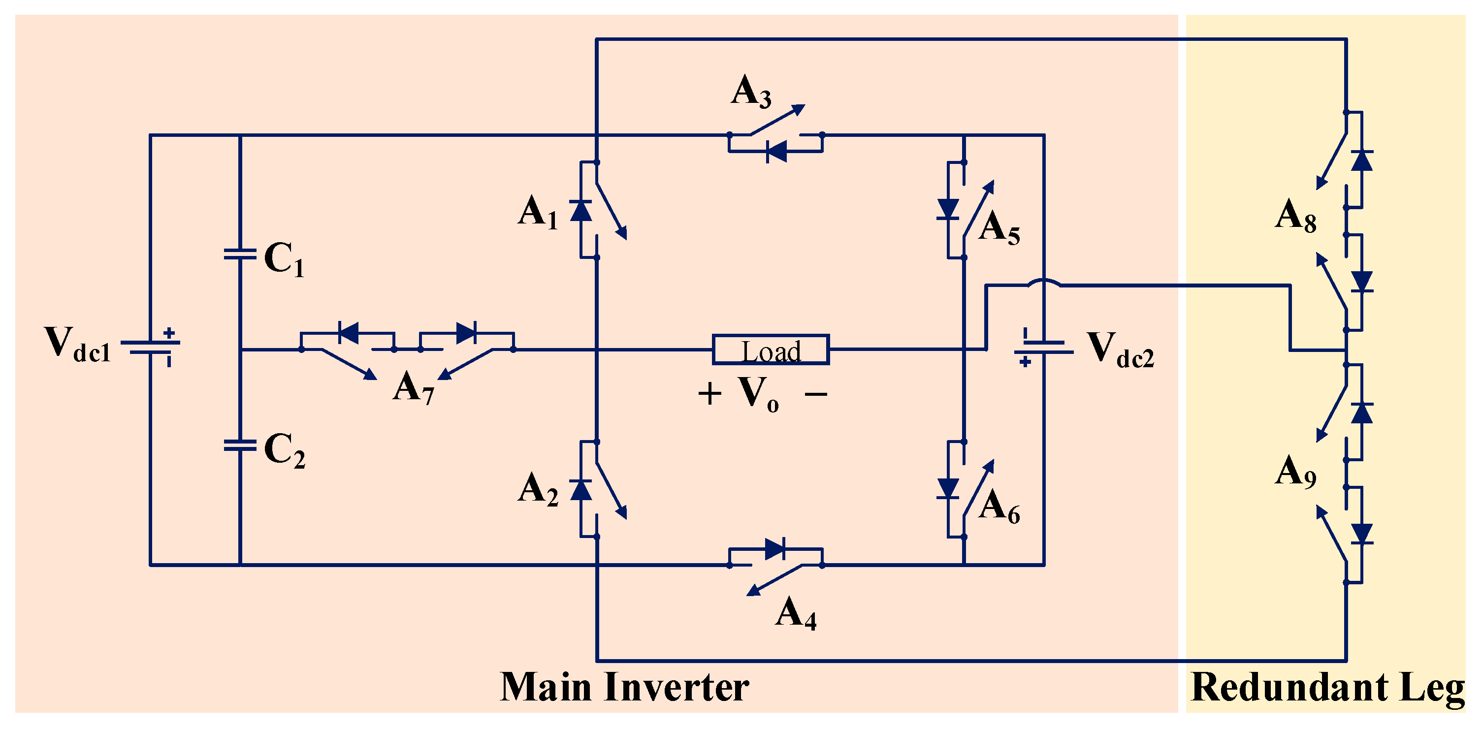
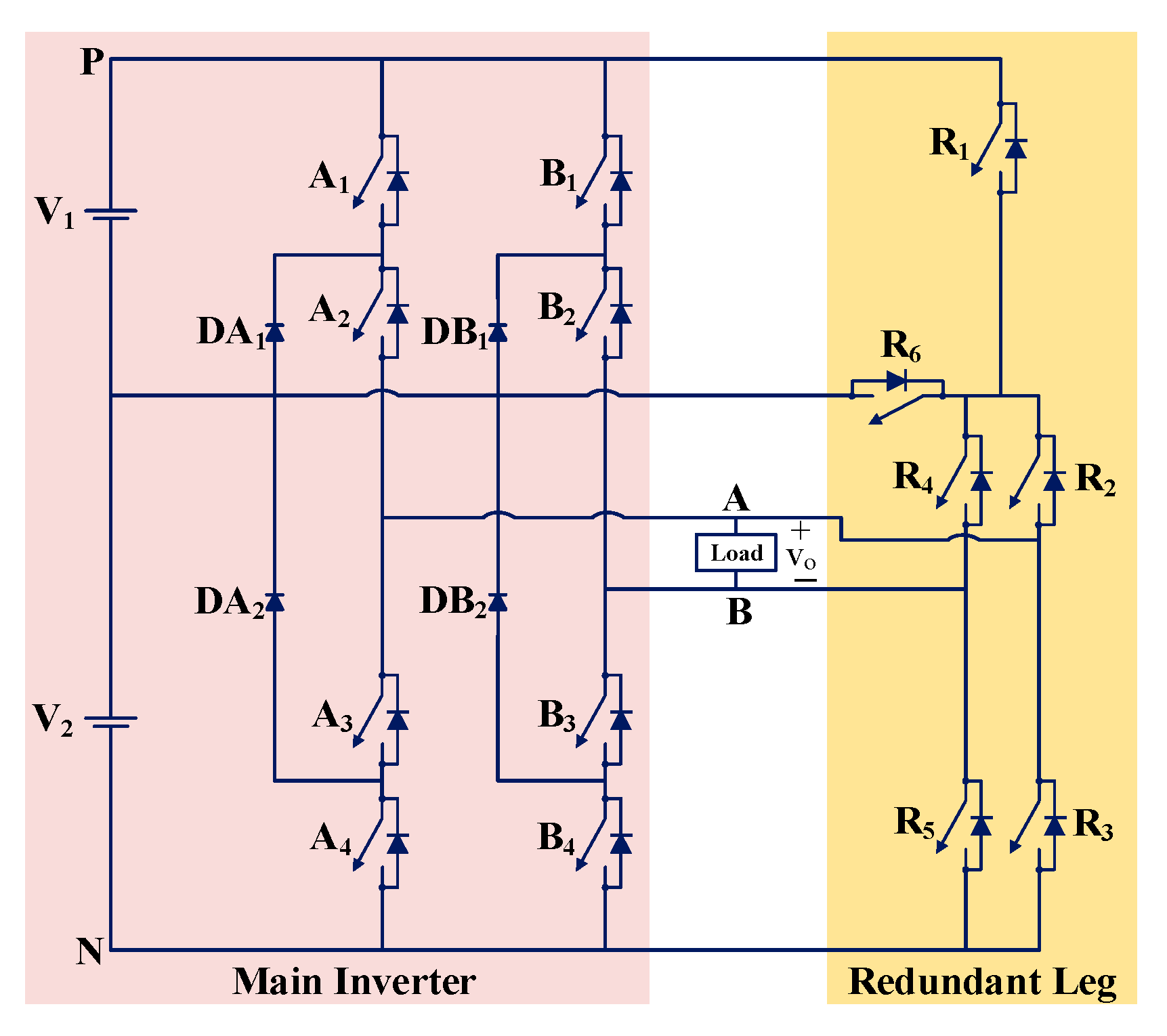
A single-phase five-level FT MLI topology (TP5) is proposed in [34]. The authors added a redundant leg to the full-bridge NPC inverter topology to make it FT. TP5 has a main inverter and a redundant leg. TP5 comprises two DC sources, four diodes, four fuses, and fourteen unidirectional switches. The circuit is shown in Figure 6. The LS-SPWM scheme is used for generating the gating pulses in the topology. The topology uses the LA FT solution for fault tolerance. This topology is able to generate voltage levels by using the same or a smaller number of switching devices (IGBTs). The efficiency achieved in the post-fault condition is the same or even higher than in the pre-fault condition. The topology tolerates SC faults by using fewer fuses compared to other topologies. The topology can handle single and multiple OC and SC switch faults in one or two legs of the main inverter circuit. The merits of the topology include no use of bidirectional switches, fewer conducting switches in post-fault conditions, and the preservation of all output voltage levels for all single and multiple (two switches) switch faults. No utilization of redundant legs’ switches under healthy conditions is the limitation of the topology.

3.1.4. TP6

Another single-phase five-level FT MLI topology (TP6) is proposed in [3]. The authors combined a conventional flying capacitor (FC) leg, cascaded H-bridge (CHB) leg, and active neutral point clamped (ANPC) leg to develop FT topology. TP6 has a main inverter and a redundant leg. It comprises one DC source, one capacitor, and twelve unidirectional switches. The circuit is shown in Figure 7. The LS-SPWM scheme is employed for generating switching pulses in the topology. The topology uses the LA FT solution for fault tolerance. The topology has the ability to tolerate single- and multiple-switch OC faults in the circuit. The merits of topology include no use of bidirectional switches, the efficiency achieved in post-fault conditions being the same as the healthy operation, preservation of the output power in the faulty condition same as in the healthy operation, and self-balancing of flying capacitor voltage. No utilization of redundant legs’ switches under healthy conditions is the limitation of the topology. The topology was used in [49] for more electric aircraft applications.

3.1.5. TP7

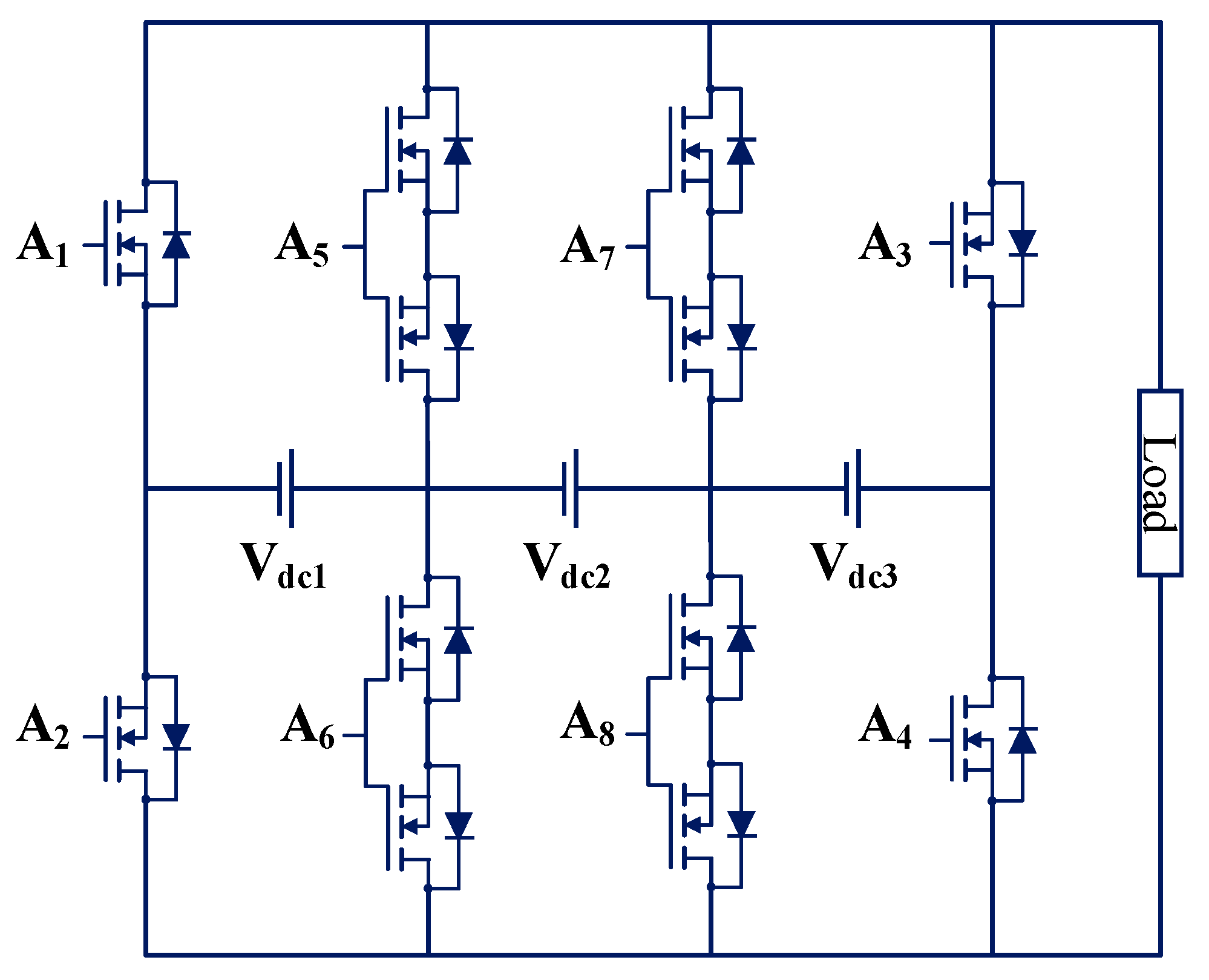
A single-phase nine-level FT MLI topology (TP7) is proposed in [35]. The FT MLI consists of the main inverter and the redundant leg. The main inverter is composed of two three-level flying capacitor legs. TP7 comprises two DC sources, two capacitors, and sixteen unidirectional switches. The circuit is shown in Figure 8.
The phase-disposition SPWM (PD-SPWM) scheme is employed for generating switching pulses in the topology. The topology uses the LA FT solution for fault tolerance. The topology does not include any bidirectional switches. The topology can generate voltage levels under single and multiple OC faults while preserving output power both in healthy and post-fault operations. The merits of this topology include the efficiency achieved in post-fault conditions being higher as compared with the healthy operation, the ability to tolerate single- and multiple-switch OC and SC faults, and the self-balancing of the flying capacitor voltage both in healthy and post-fault operation. No utilization of redundant legs’ switches under healthy conditions is the limitation of the topology.

3.1.6. TP8 and TP9

A single-phase five-level FT MLI topology is proposed in [31]. Two topologies are proposed in the publication. In the first topology (TP8), there is a loss of levels in output voltage after a fault; this is termed partial fault tolerance. In the second topology (TP9), there is no loss of levels in output voltage after a fault; this is termed complete fault tolerance. The circuits for partial and complete fault tolerance are shown in Figure 9a,b, respectively. The LS-SPWM scheme is employed for generating switching pulses in both topologies. TP8 and TP9 use IHR and LA FT solutions, respectively, for fault tolerance.
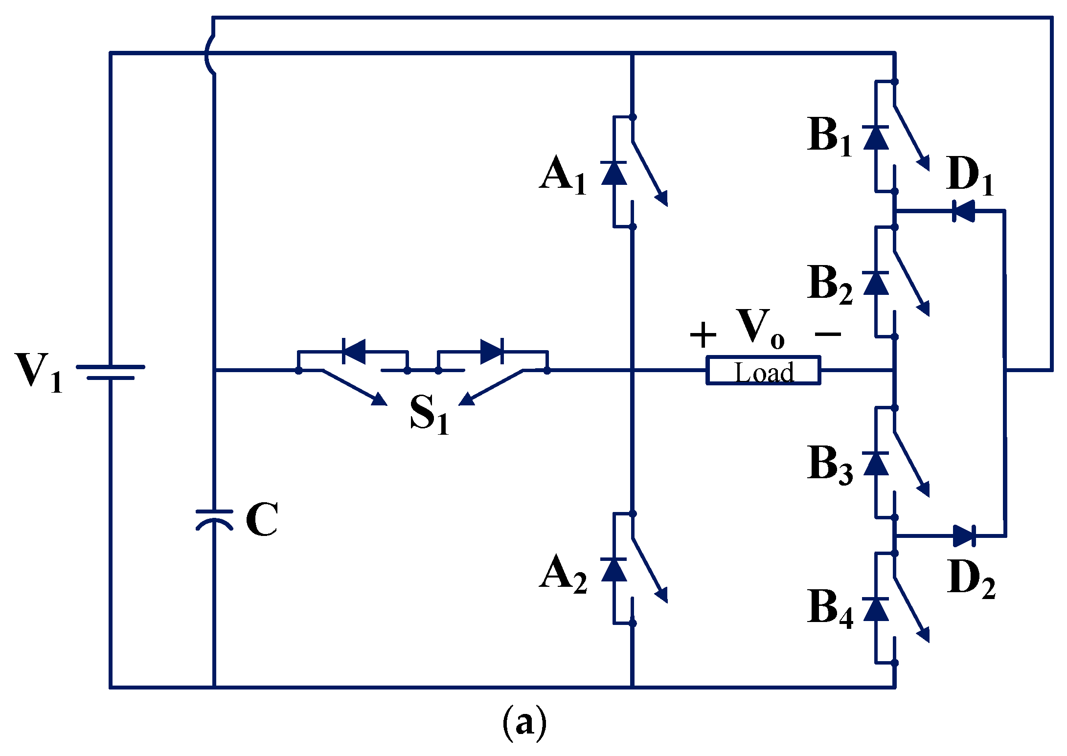
The first part of the publication discusses the partial solution to the faults since there are losses of levels. TP8 (as shown in Figure 9a) comprises one DC source, one capacitor, two diodes, one bidirectional switch, and six unidirectional switches. This partial solution topology can be generalized for any number of levels by cascading basic topology. The topology achieves the self-balancing of the capacitor voltage both in healthy and faulty operation. The capacitor voltage ripples increase under post-fault operation. This topology can tolerate all single-switch OC and SC faults in the circuit with loss of levels. The merits of the topology include the self-balancing of the capacitor voltage under faulty conditions, 100% utilization of all switches under healthy conditions, and FT MLI can be extended by cascading similar units depending upon the number of output voltage levels needed. The use of bidirectional switches, the inability to preserve all output voltage levels for all single-switch faults, the increase in capacitor voltage ripples under post-fault operating conditions, and the inability to tolerate multiple-switch faults are the limitations of the topology.
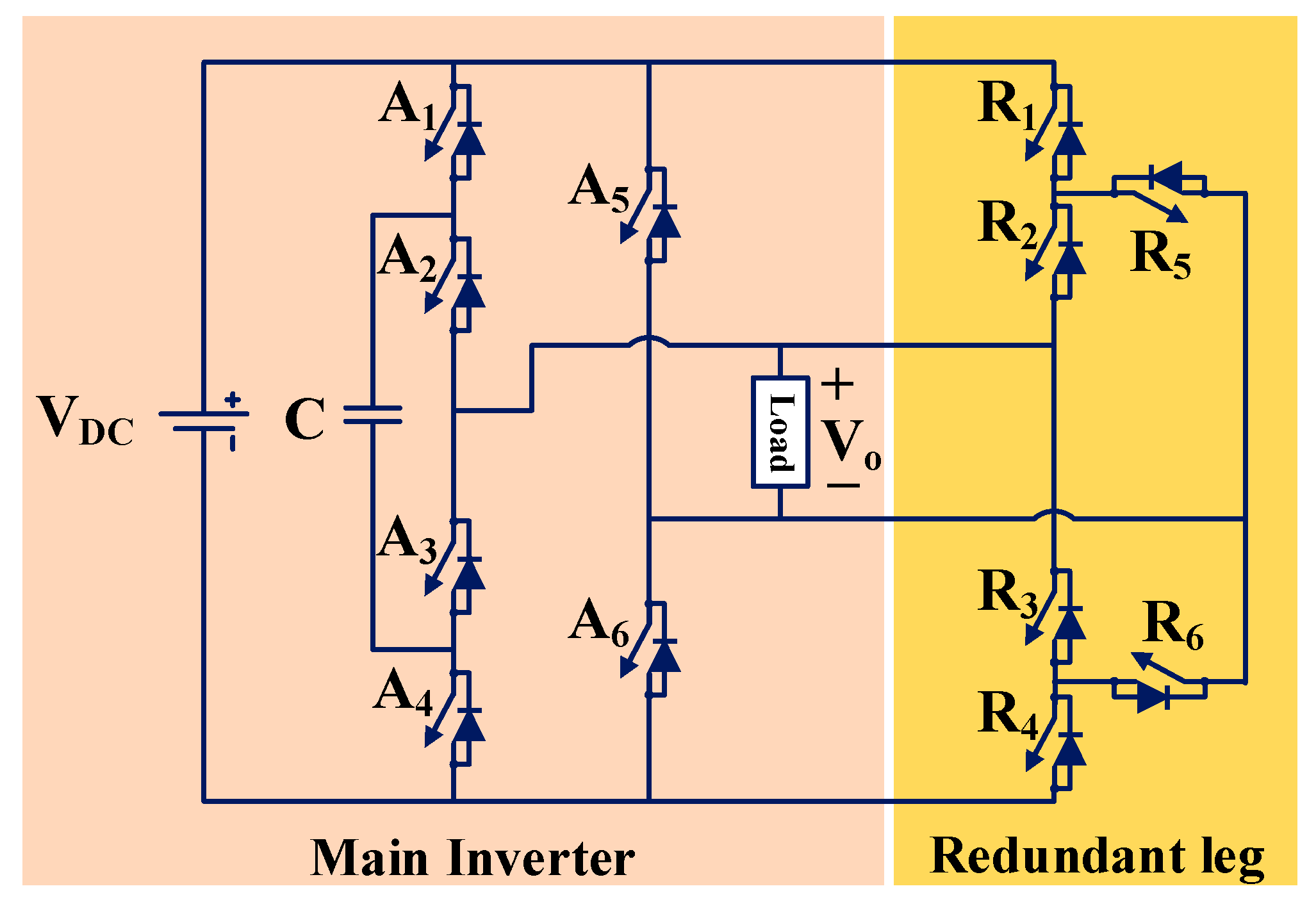
The second part of the publication discusses the complete solution to the faults since there is no loss of levels. TP9 (as shown in Figure 9b) has a main inverter and a redundant leg. It consists of one DC source, one capacitor, two diodes, three bidirectional switches, and eight unidirectional switches. The topology TP9 achieves the self-balancing of the capacitor voltage both in healthy and faulty operation. The capacitor voltage ripples under post-fault operation remain the same as in pre-fault operation. The topology can tolerate all single-switch OC and SC faults in the circuit without loss of levels. The redundant legs’ switches are only utilized in the case of a fault. The merits of the topology include the self-balancing of the capacitor voltage under faulty conditions, no increase in capacitor voltage ripples under post-fault operating conditions, and the preservation of all output voltage levels for all single-switch faults. The use of bidirectional switches, higher cost, no utilization of redundant legs’ switches under healthy conditions, higher number of conducting switches under post-fault condition (hence it results in higher switching power loss under post-fault condition), and inability to tolerate multiple-switch faults are the limitations of the topology.

3.1.7. TP10

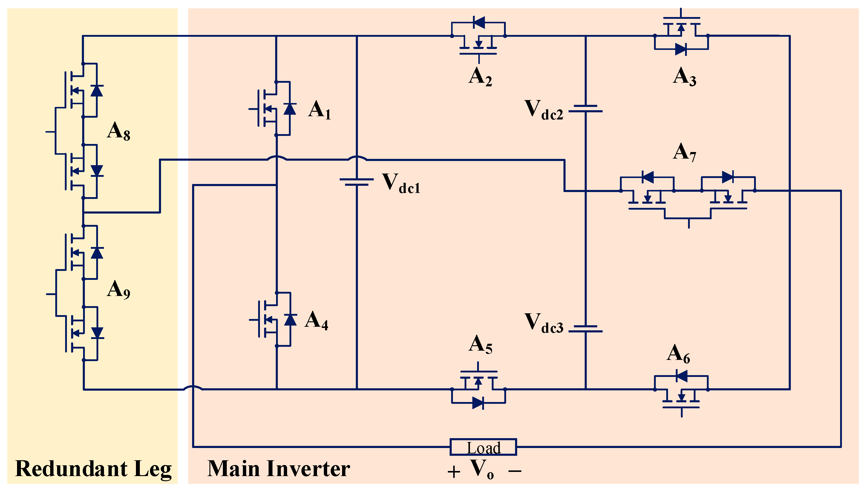
An FT MLI topology (TP10) presented in [50] by modifying the FT MLI topology given in [31]. The authors added a novel redundant leg to the main inverter. TP10 consists of one DC source, one capacitor, two diodes, one bidirectional switch, and twelve unidirectional switches. The circuit of topology TP10 is shown in Figure 10.
The LS-SPWM scheme is employed for generating switching pulses in the topology. TP10 uses the LA FT solution for fault tolerance. The main inverter has a drawback of lesser post-fault efficiency as compared to pre-fault efficiency. This limitation is solved in this work by proposing a novel redundant leg. The novel redundant leg provides an overload-current-sharing characteristic, which is absent in the original topology. It is capable of working at reduced voltage levels if a switch fault occurs. It can tolerate single-switch OC faults with preserved power. Overload-current-handling capability by utilizing redundant legs’ switches under healthy conditions is the merit of the topology. The limitations of the topology include a higher number of conducting switches under post-fault conditions (hence, it results in higher switching power loss under post-fault conditions).

3.1.8. TP11

A single-phase five-level FT MLI topology (TP11) is proposed in [51]. The topology TP11 is capable of tolerating OC and SC faults for single and multiple switches. TP11 comprises one DC source, one capacitor, two diodes, four fuses, and twelve unidirectional switches. The circuit of the single-phase five-level FT MLI is shown in Figure 11. It consists of a main inverter and a redundant leg. The main inverter topology is constructed by using the legs of conventional three-level neutral point clamped inverter and three-level flying capacitor inverter. The redundant leg is constructed by using a conventional three-level cascaded H-bridge (CHB) inverter. The LS-SPWM scheme is employed for generating switching pulses in the topology. TP11 uses the LA FT solution for fault tolerance. The main feature of the topology is to tolerate single- and multiple-switch faults, no matter whether they are OC or SC faults. The merits of the topology include inherent capacitor voltage balancing under both single-switch and multiple-switch faults; multiple-switch faults tolerance for any pair, triplet, or quadruple of switches; and output power will remain to preserve post-fault, similar to pre-fault output power. Decreased voltage levels (leading to higher harmonic distortions of the output voltage waveform) and no utilization of redundant legs’ switches under healthy operation are the limitations of the topology.

3.1.9. TP12

A single-phase five-level FT MLI (TP12) is proposed in [37]. The authors named it DITHB, i.e., developed inverter with two half-bridges. TP12 comprises two DC sources and nine unidirectional switches. The circuit for TP12 is shown in Figure 12. The LS-SPWM scheme is employed for generating switching pulses in the topology. TP12 uses the IHR FT solution for fault tolerance. In faulty conditions, the topology can generate three levels for a single-switch OC fault. This topology can tolerate a single-switch OC fault in the circuit with a loss of levels. A higher number of conducting switches under healthy and faulty conditions is the limitation of the topology. The following are the merits of the topology:
  • It has switching states which can bring two sources in parallel. Due to this advantage, it is possible to maintain power in post-fault similar to the pre-fault power.
  • Single unit can be connected in series depending upon the number of output voltage levels required.

3.1.10. TP13

A single-phase thirteen-level FT MLI (TP13) is proposed in [52]. TP13 comprises three DC sources, three bidirectional switches, and six unidirectional switches. The circuit for TP13 is shown in Figure 13. The nearest level control PWM (NLC-PWM) scheme is employed for generating switching pulses in the topology. TP13 uses the SA FT solution for fault tolerance. This topology can tolerate a single-switch OC fault in the circuit with a loss of levels. The merit of the topology includes the ability to tolerate all single-switch OC faults. The limitations of the topology include a higher number of bidirectional switches and the inability to tolerate multiple-switch faults.

3.1.11. TP14

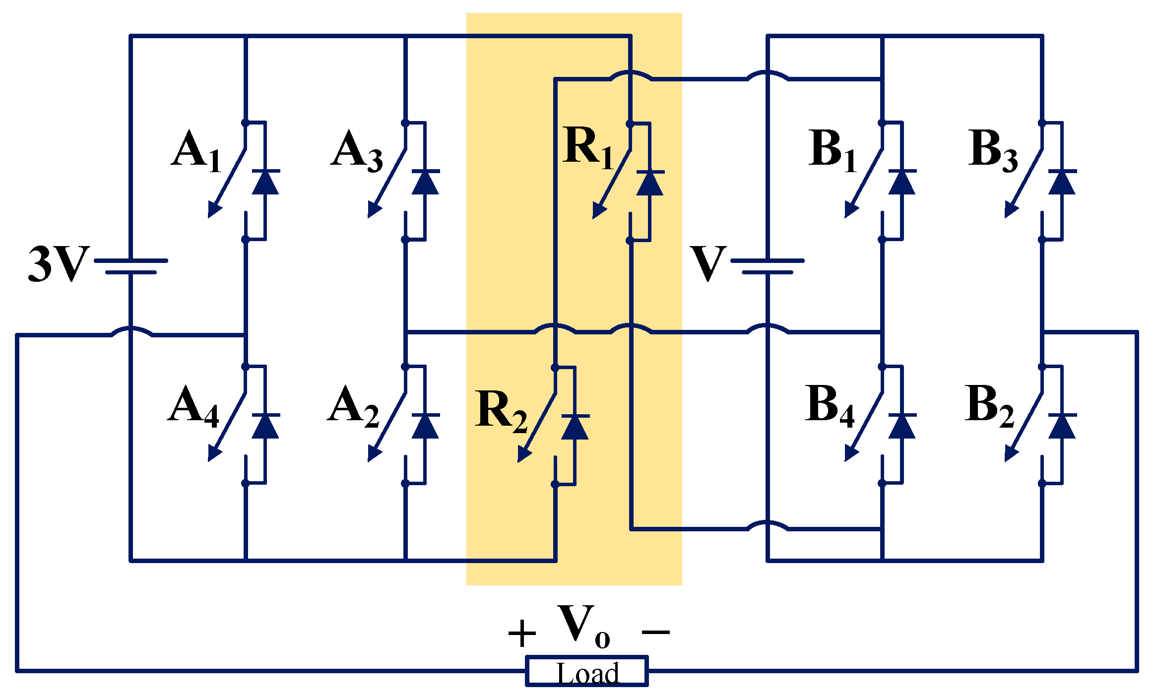
The authors of another study modified a single-phase nine-level cascaded H-bridge (CHB) inverter with an asymmetrical configuration for fault tolerance in [39]. TP14 comprises two DC sources and ten unidirectional switches. The circuit for TP14 is shown in Figure 14. A hybrid modulation technique comprising NLC and LS-PWM is employed for generating switching pulses in the topology. TP14 uses the SA FT solution for fault tolerance. It can tolerate switch OC faults. It utilizes two redundant switches, R1 and R2, to provide fault tolerance under faulty conditions. The merit of the topology includes the ability to tolerate all single-switch OC faults. The inability to tolerate all multiple-switch OC and SC faults is the limitation of the topology.

3.1.12. TP15 and TP16

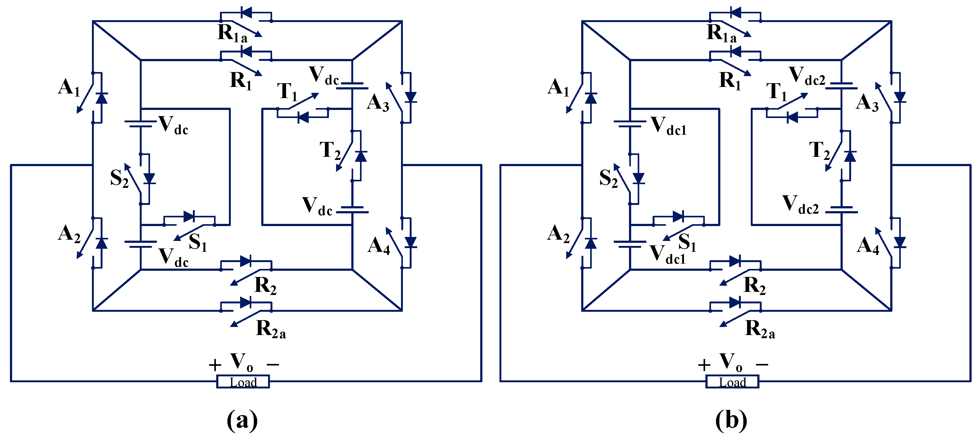
A generalized single-phase FT MLI is proposed in [53]. It can work in symmetric and asymmetric modes. When all the sources are equal, the mode of operation is called symmetric, whereas when sources are different, the mode of operation is called asymmetric. The circuit of a single-phase nine-level FT MLI (TP15) is shown in Figure 15a. The circuit of a single-phase seventeen-level FT MLI (TP16) is shown in Figure 15b. TP15 and TP16 comprise four DC sources and twelve unidirectional switches. The modified level-shifted carrier PWM (LSCPWM) scheme is used for generating the gating pulses in the topology. Both topologies use the IHR FT solution for fault tolerance. The proposed topology can tolerate single- and multiple-switch OC and SC faults. The proposed topology can operate under both symmetric and asymmetric modes. The proposed topology can generate higher voltage levels with respect to its modular structure. The switches R1a and Ra2 operate only in the case of switch R1 and R2 failure. The ability to tolerate both source and/or switches faults and the ability to extend topology depending upon the number of output voltage levels requirement are the merits of the topology. No utilization of switches R1a and Ra2 under healthy operation is the limitation of the topology.

3.1.13. TP17

A single-phase five-level FT MLI (TP17) is proposed in [8]. TP17 comprises two DC sources, two diodes, one bidirectional switch, and six unidirectional switches. The circuit of TP17 is shown in Figure 16. The phase-disposition sinusoidal PWM (PD-SPWM) scheme is employed for generating switching pulses in the topology. The topology uses the SA FT solution for fault tolerance. If a fault occurs in the source and/or switch, the topology can generate three voltage levels instead of five levels. The output voltage magnitude reduces after the fault. Therefore, to maintain the rated output voltage, a transformer is used. The merits of the topology are as follows:
  • TP17 topology is capable of tolerating faults caused by the failure of the source.
  • TP17 reduces the uneven charging of batteries that is caused to partial shading or hotspots on one side of the PV panels due to energy-balancing between sources.
The limitations of the topology are as follows:
  • Use of bidirectional switch.
  • Inner leg switches in the NPC leg are not FT.
  • Implementation of center-tapped transformer.

3.1.14. TP18

A single-phase nine-level FT MLI topology (TP18) is proposed in [40]. TP18 comprises two DC sources, one capacitor, three bidirectional switches, and six unidirectional switches. The circuit of TP18 is shown in Figure 17.
The PD-SPWM scheme is used for generating the gating pulses in the topology. The topology uses the IHR FT solution for fault tolerance. The topology can generate nine levels, using three bidirectional and six unidirectional switches and a capacitor under healthy operation. It does not need any redundant leg or extra switches. It is capable of working at reduced voltage levels if a switch fault occurs. The merits of the topology include 100% utilization of all switches in healthy condition, and the switching scheme proposed in the work achieves the natural capacitor voltage balancing without any external circuit. The use of a higher number of bidirectional switches is the limitation of the topology.

3.1.15. TP19

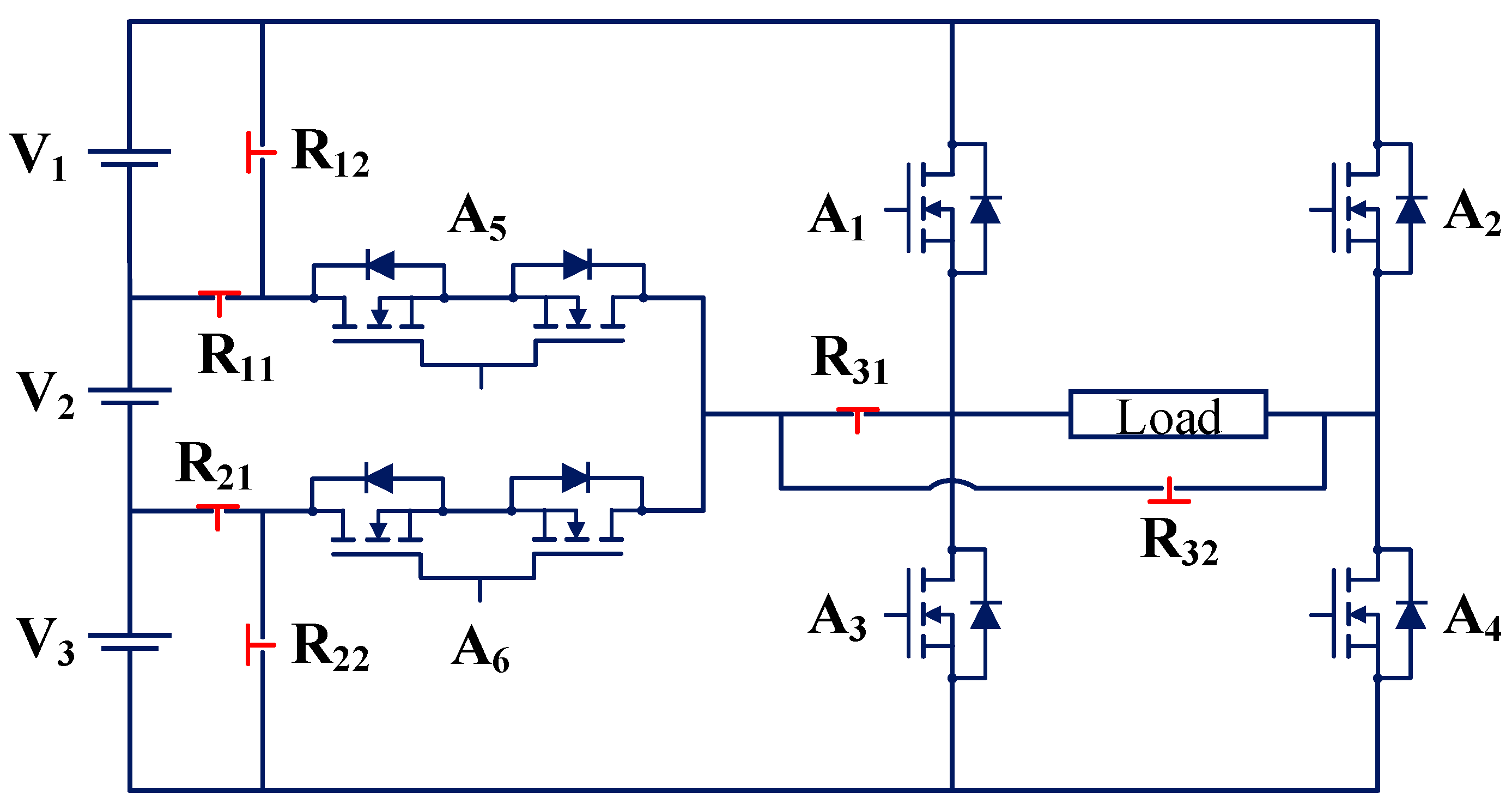
A single-phase five-level FT MLI (TP19) is proposed in [54]. The proposed inverter topology is capable of tolerating both OC and SC faults on all single switches and some multiple switches. TP19 comprises two DC sources, nine fuses, three bidirectional switches, and six unidirectional switches. The circuit of TP19 is shown in Figure 18. The LS-SPWM scheme is used for generating the gating pulses in the topology. The topology uses the SA FT solution for fault tolerance. The switches A6 and A7 operate only under FT operation. A fast-acting switch is used in series with each switch to detect SC faults. The controller sees a short circuit as an open circuit and provides separate operations for OC and SC faults. The merits of the topology include the ability to tolerate both OC and SC faults and the ability to provide rated output voltage and power under any switch fault. The use of a higher number of bidirectional switches and no utilization of switches A6 and A7 under healthy conditions are the limitations of the topology.

3.1.16. TP20

A single-phase nine-level FT MLI topology (TP20) is proposed in [41]. TP20 comprises two DC sources, two capacitors, three bidirectional switches, and six unidirectional switches. The circuit of TP20 is shown in Figure 19. The LS-SPWM scheme is used for generating the gating pulses in the topology. The topology uses the IHR FT solution for fault tolerance. The topology is unable to provide rated output voltage and power in some faults. A smaller number of conducting switches under post-fault conditions is the merit of the topology. The use of a higher number of bidirectional switches and the inability to tolerate fault on the bidirectional switch connected between the capacitor and load terminal are the limitations of the topology [35,55].

3.1.17. TP21

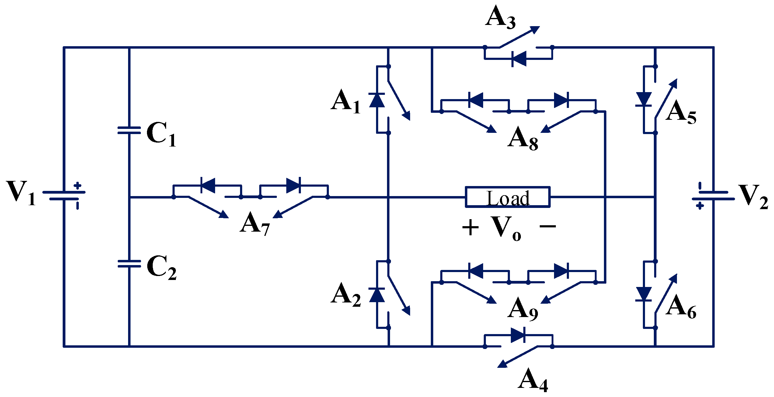
A single-phase eleven-level FT MLI topology (TP21) is proposed in [56]. TP21 comprises three DC sources, three bidirectional switches, and six unidirectional switches. The circuit of TP21 is shown in Figure 20. The publication deals only with OC faults. The switches A8 and A9 work only under faulty conditions. The NLC-PWM scheme is employed for generating switching pulses in the topology. The topology uses the SA FT solution for fault tolerance. The ability to tolerate all single-switch OC faults and some multiple-switch OC faults is the merit of the topology. The use of bidirectional switches, no utilization of switches A8 and A9 under healthy conditions, and the inability to tolerate SC faults are the limitation of the topology.

3.1.18. TP22

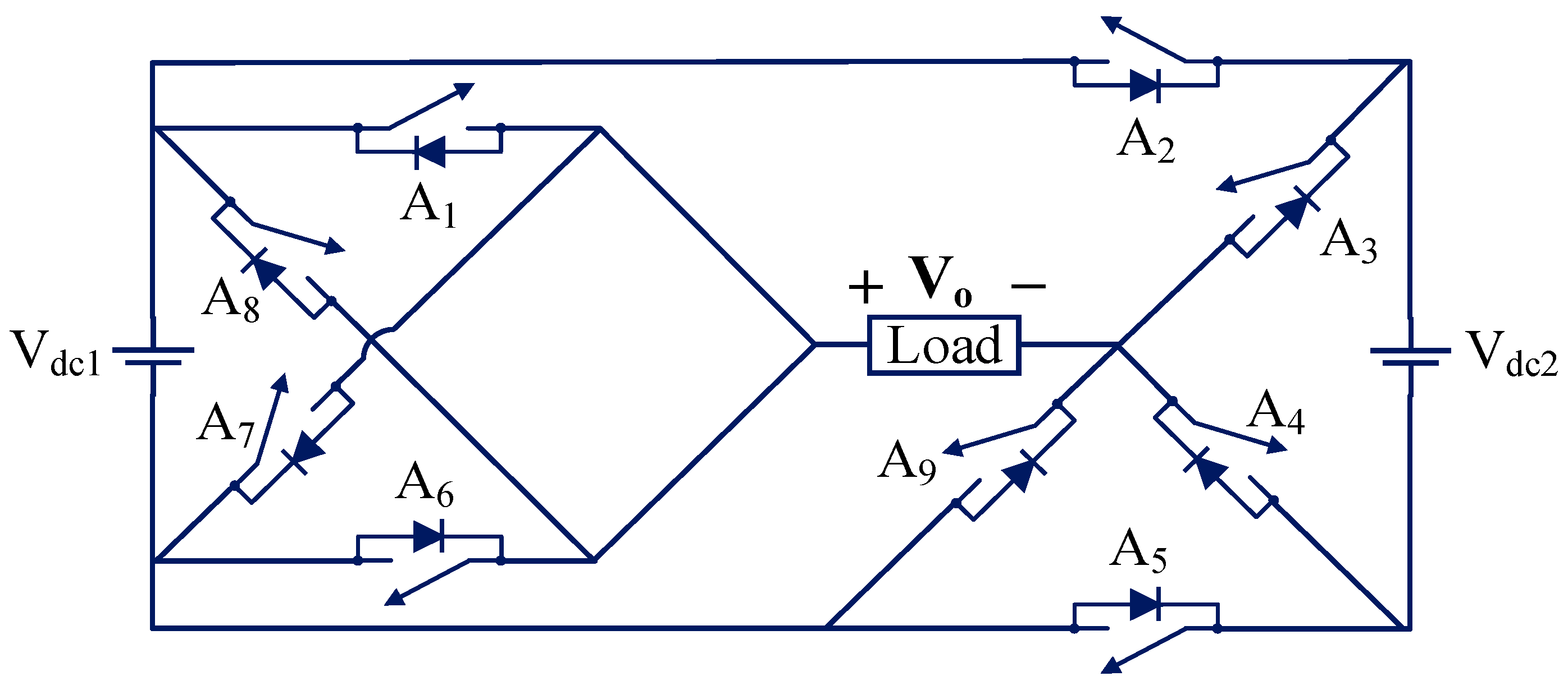
A fifteen-level FT MLI topology (TP22) is proposed in [57], and it is shown in Figure 21. TP22 comprises four DC sources, one bidirectional switch, and ten unidirectional switches. This FT MLI topology does not utilize additional hardware components to create redundancy for FT operation. It utilizes inherent hardware redundancy for fault tolerance. It is able to tolerate all single-switch OC faults. A combination of nearest level modulation (NLM) and selective harmonic elimination (SHE) is employed for generating switching pulses in the topology. The topology uses the IHR FT solution for fault tolerance. The merit of the topology includes 100% utilization of all switches under healthy conditions. The use of a higher number of DC sources is the limitation of the topology.

3.1.19. TP23

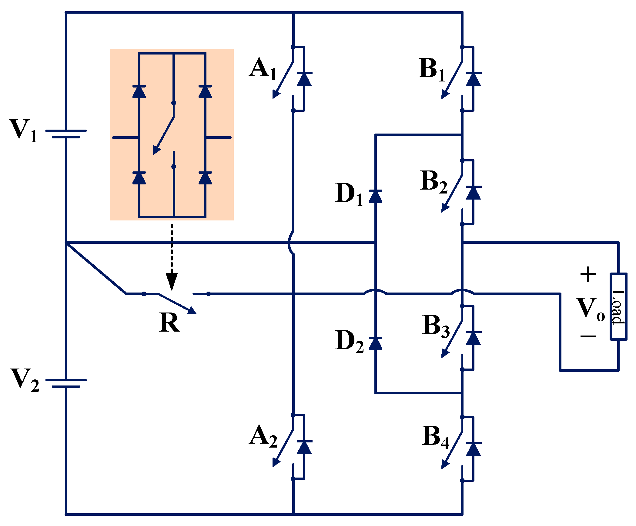
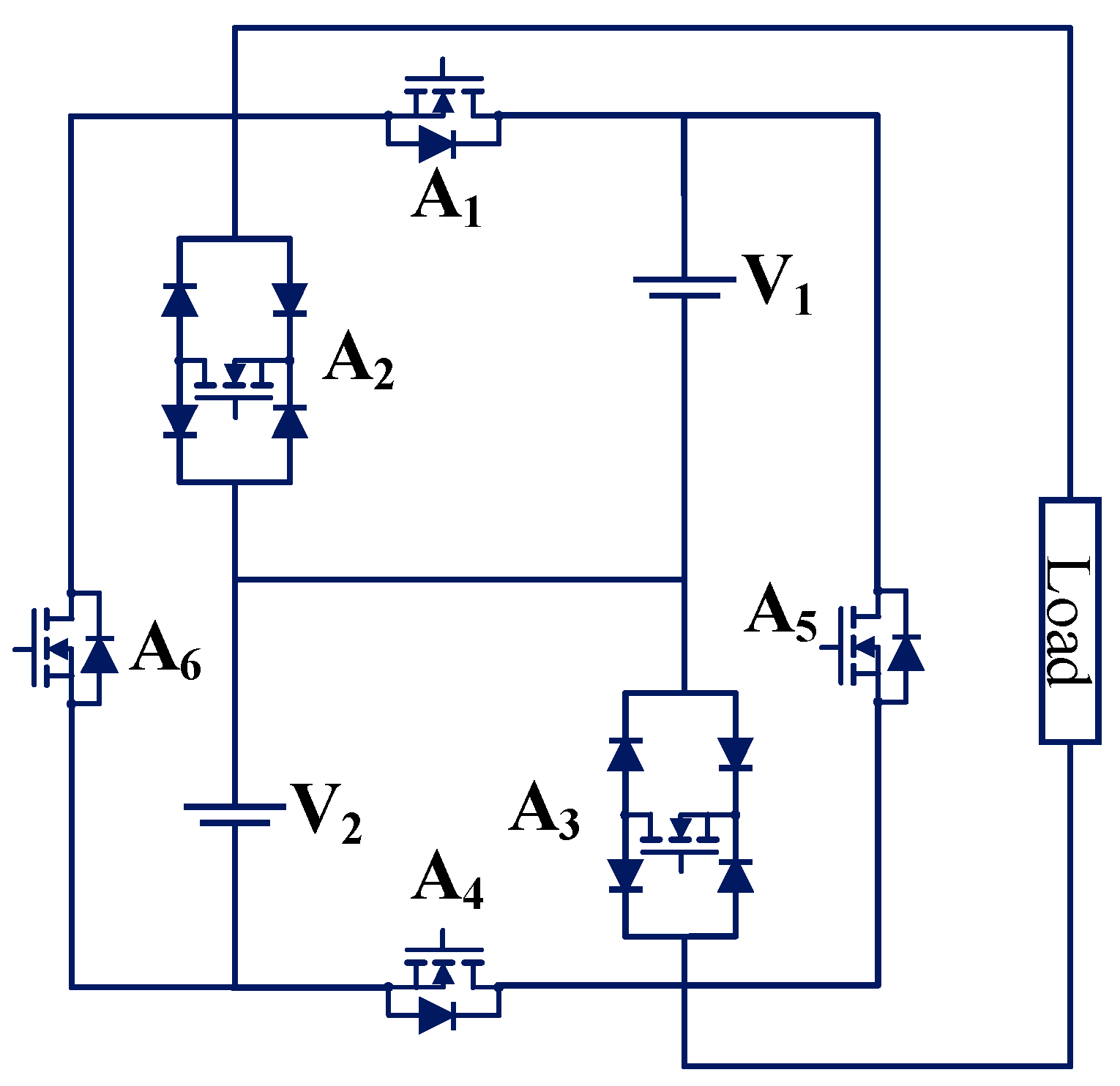
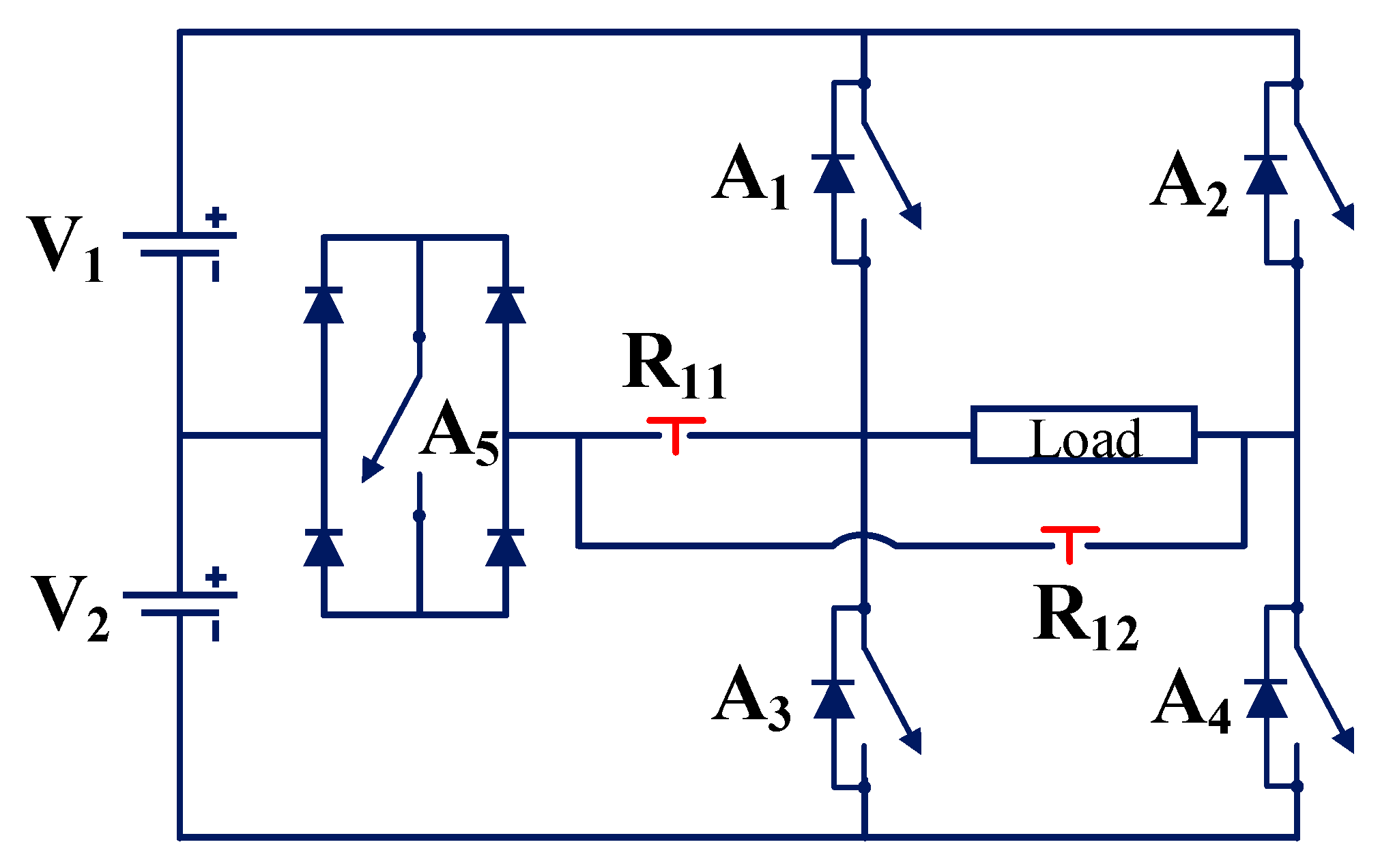
Other authors proposed a five-level FT MLI topology (TP23) in [38] by modifying a five-level modified PUC (MPUC5) inverter topology, which is shown in Figure 22. Three redundant switches (A7, A8, and A9) are added to the original MPUC5. TP23 comprises two DC sources and nine unidirectional switches. This topology can tolerate all single-switch OC faults. The NLC-PWM scheme is used for generating the gating pulses in the topology. The topology uses the SA FT solution for fault tolerance. The use of a smaller number of switches is the merit of the topology. The limitations of the topology include the inability to tolerate SC faults and multiple-switch faults.

3.1.20. TP24 and TP25

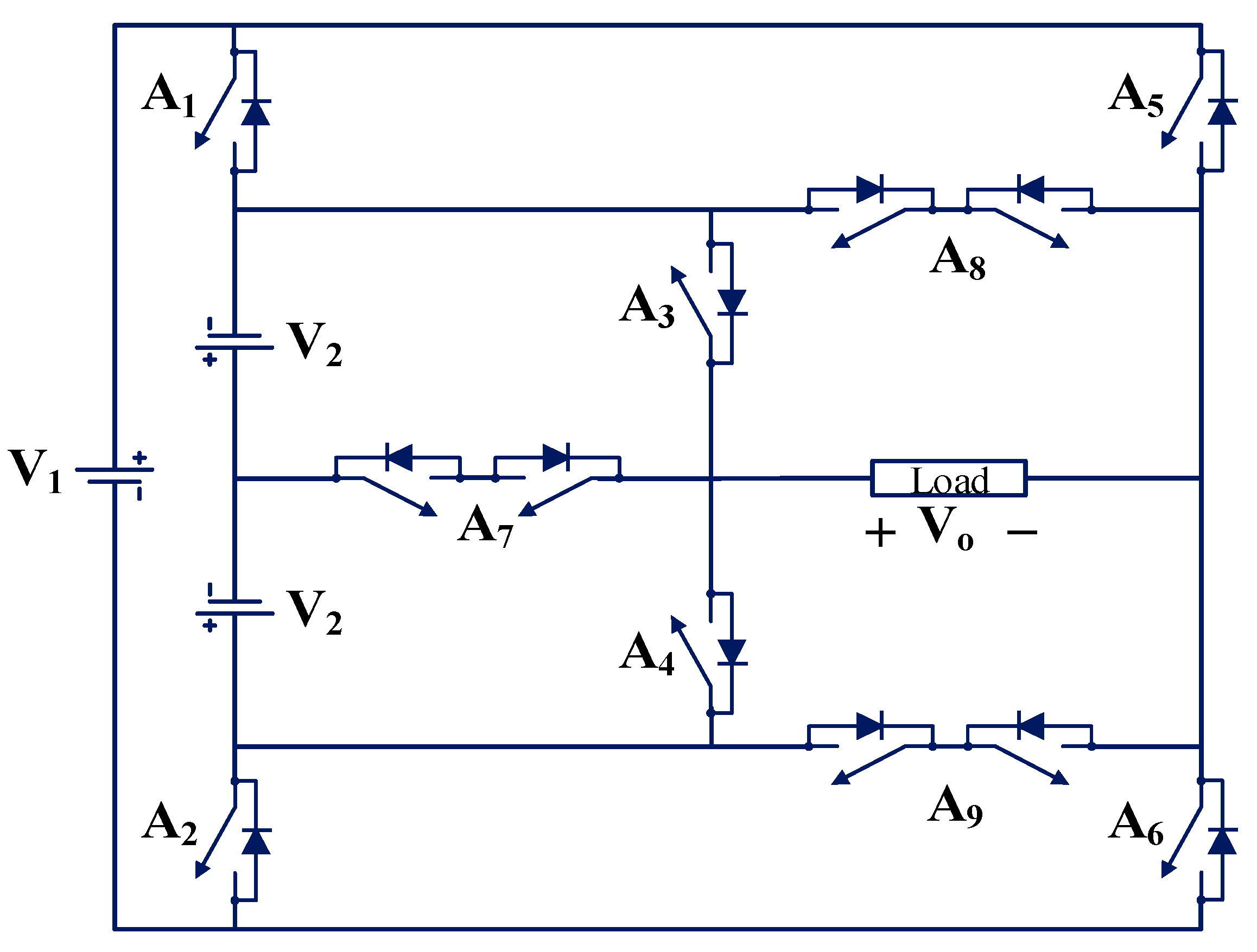
The authors in [42] proposed FT MLI topologies (TP24 and TP25), and these are shown in Figure 23. Topologies TP24 and TP25 comprise four DC sources and twelve unidirectional switches. Two switches, A7r and A8r, are used as redundant switches. It can generate 9 levels and 17 levels of waveform depending upon the values of DC sources. The topology TP24 generates nine levels with Vdc1 = Vdc2 = Vdc3 = Vdc4 = V in the symmetric mode of operation. The topology TP25 generates 17 levels with Vdc1 = Vdc2 = V, and Vdc3 = Vdc4 = 3V in the asymmetric mode of operation. It can tolerate all single- and multiple-switch OC faults. The modified LSCPWM scheme is used for generating the gating pulses in the topology. TP24 and TP25 use the IHR FT solution for fault tolerance. The merit of the topology includes its lower total standing voltage (TSV). The inability to tolerate the SC fault on all switches is the limitation of the topology.

3.1.21. TP26

A single-phase five-level FT MLI is proposed in [58], and it is shown in Figure 24. It comprises two DC sources, two bidirectional switches, and four unidirectional switches. The POD-SPWM scheme is used for creating the gating pulses in the topology. The topology uses the IHR FT solution for fault tolerance. The topology can tolerate OC single-switch faults in all switches and some OC double-switch faults. The topology can be generalized for the “N” number of levels. This FT MLI topology can be used in solar-based charging station applications. The topology is used in [59] for wave power plant applications. The merit of the topology includes 100% utilization of all switches under healthy conditions. The use of bidirectional switches is the limitation of the topology.

3.1.22. TP27 and TP28

A single-phase seven-level FT MLI is proposed in [60], and it is shown in Figure 25. It comprises three DC sources, five bidirectional switches, and five unidirectional switches. The topology is modular in nature. It can be generalized for the “N” number of levels. The seven-level FT MLI can be modified and made into a nine-level FT MLI by adding a module consisting of one DC source, one bidirectional switch, and one unidirectional source. The POD-SPWM scheme is used for creating the gating pulses in the topology. TP28 uses the IHR FT solution for fault tolerance. The topology can tolerate OC single- and double-switch faults in switches and OC and SC faults in sources. The modular nature and ability to extend the topology for the “N” number of output voltage levels are the benefits of this topology.

3.1.23. TP29

A single-phase FT MLI is proposed in [61] for multi-string photovoltaic (PV) applications, and it is shown in Figure 26. It consists of two H-bridges and comprises four DC sources, two bidirectional switches, and ten unidirectional switches. This topology can synthesize a nine-level output voltage under symmetric conditions (V1 = V2 = V3 = V4 = V/4). This topology can synthesize a thirteen-level output voltage under asymmetric conditions (V1 = V2 = V/6 and V3 = V4 = V/3). The PD-SPWM scheme is used for creating the gating pulses in the topology. The topology uses the IHR FT solution for fault tolerance. In the event of partial shading of PV panels, TP29 is capable of energy balancing between sources.

3.1.24. TP30

A single-phase seven-level FT MLI is proposed in [62], as shown in Figure 27. It comprises three DC sources, two bidirectional switches, and eight unidirectional switches. The NLC-PWM technique is employed for generating the switching pulses in the topology. The topology uses the IHR FT solution for fault tolerance. The topology can be extended to the “N” number of output voltage levels. It can tolerate single-switch OC faults on switches.

3.1.25. TP31

A single-phase nine-level FT MLI is proposed in [63], and it is shown in Figure 28. It comprises four DC sources, three bidirectional switches, and six unidirectional switches. The POD-SPWM scheme is used for creating the gating pulses in the topology. The topology uses the SA FT solution for fault tolerance. It can tolerate single- and multiple-switch OC faults.

3.1.26. TP32

A single-phase five-level FT MLI is proposed in [64], and it is shown in Figure 29. It comprises two DC sources, two bidirectional switches, and four unidirectional switches. The NLC-PWM technique is employed for generating the switching pulses in the topology. The topology uses the IHR FT solution for fault tolerance. The topology can be extended to the “N” number of output voltage levels. TP32 can tolerate OC/SC faults in sources. It can also tolerate all single OC faults and some multiple OC faults in switches.

3.1.27. TP33

A single-phase FT MLI is proposed in [65], and it is shown in Figure 30. It comprises three DC sources, four bidirectional switches, and four unidirectional switches. This topology can synthesize a seven-level output voltage under symmetric conditions (same DC sources) and term it TP33A. This topology can synthesize a thirteen-level output voltage under asymmetric conditions (different DC sources) and term it TP33B. The NLC-PWM technique is employed for generating the switching pulses in the topology. The topology uses the IHR FT solution for fault tolerance. The topology can be extended to the “N” number of output voltage levels. TP33 can tolerate OC faults in all switches. A higher number of bidirectional switches is the limitation of this topology.

3.1.28. TP34

A single-phase seven-level FT MLI is proposed in [66], and it is shown in Figure 31. It comprises three DC sources and eight unidirectional switches. A sine wave reference with an inverted sine carrier pulse generation scheme is used for creating the gating pulses in the topology. The topology uses the IHR FT solution for fault tolerance. It can tolerate all single-switch OC faults.

3.1.29. TP35

A single-phase five-level FT MLI is proposed in [67], as shown in Figure 32. It comprises a single DC source, two capacitors, two bidirectional switches, and four unidirectional switches. The POD-SPWM scheme is used for creating the gating pulses in the topology. The topology uses the IHR FT solution for fault tolerance. TP35 can tolerate all single-switch OC faults. It can also tolerate any OC fault occurring in any leg of the H-bridge. This topology also achieves the self-balancing of the DC-link capacitors.

3.1.30. TP36

A single-phase seven-level FT MLI is proposed in [68], and it is shown in Figure 33. It comprises two DC sources, two capacitors, three bidirectional switches, and six unidirectional switches. The LS-SPWM scheme is used for creating the gating pulses in the topology. The topology uses the SA FT solution for fault tolerance. TP36 can tolerate all single-switch OC faults. This topology also achieves the self-balancing of the DC-link capacitors.

3.1.31. TP37

A single-phase fifteen-level FT MLI is proposed in [69], and it is shown in Figure 34. It comprises a single DC source, eight capacitors, six bidirectional switches, and twenty-four unidirectional switches. The NLM-PWM scheme is used for creating the gating pulses in the topology. The topology uses the IHR FT solution for fault tolerance. TP37 can boost the input voltage seven times according to the concept of a switch capacitor. This topology can tolerate both OC and SC faults on single and multiple switches. This topology also achieves the self-balancing of the DC-link capacitors. The requirement of a single DC source is the merit of the topology.

3.1.32. TP38

A single-phase nine-level FT MLI is proposed in [70], and it is shown in Figure 35. It comprises four DC sources, two bidirectional switches, and eight unidirectional switches. POD-SPWM and NLC-PWM schemes are used for creating the gating pulses in the topology. The topology uses the IHR FT solution for fault tolerance. TP38 can tolerate all single-switch OC faults. The requirement of a higher number of DC sources is the limitation of the topology.

3.1.33. TP39

A single-phase nine-level FT MLI is proposed in [71], and it is shown in Figure 36. It comprises two DC sources, two capacitors, four bidirectional switches, and six unidirectional switches. The LS-SPWM scheme is used for creating the gating pulses in the topology. The topology uses the SA FT solution for fault tolerance. TP39 achieves self-voltage balancing of DC-link capacitors under healthy and faulty conditions. The topology can tolerate both single-switch and multiple-switch faults. The use of a higher number of bidirectional switches is the limitation of the topology.

3.1.34. TP40

A single-phase five-level FT MLI topology is proposed in [72]. The authors added a redundant leg to the conventional five-level NPC inverter to make it FT. The topology has a main inverter and a redundant leg. It comprises a single DC source, six diodes, two capacitors, and fourteen unidirectional switches. The circuit is shown in Figure 37. The LS-SPWM scheme is used for creating the gating pulses in the topology. The topology uses the LA FT solution for fault tolerance. TP40 can tolerate both single-switch and multiple-switch OC and SC faults.

3.1.35. TP41

A single-phase seven-level FT MLI is proposed in [73], and it is shown in Figure 38. It comprises three DC sources, six relays, two bidirectional switches, and four unidirectional switches. The NLC-PWM technique is employed for generating the switching pulses in the topology. The topology uses the IHR FT solution for fault tolerance. TP41 can tolerate all single-switch OC faults.

3.1.36. TP42

A single-phase five-level FT MLI is proposed in [74], and it is shown in Figure 39. It comprises two DC sources, one bidirectional switch, and six unidirectional switches. The LS-PWM scheme is used for creating the gating pulses in the topology. The topology uses the IHR FT solution for fault tolerance. TP42 can tolerate all single-switch OC faults.

3.1.37. TP43

A single-phase nine-level FT MLI topology is proposed in [75]. The topology has a main inverter and a redundant leg. It comprises two DC sources, two capacitors, three bidirectional switches, and six unidirectional switches. The circuit is shown in Figure 40. The LS-SPWM scheme is employed for generating switching pulses in the topology. The topology uses the LA FT solution for fault tolerance. TP43 can tolerate all single-switch OC faults.

3.1.38. TP44

A single-phase five-level FT MLI is proposed in [76], and it is shown in Figure 41. It comprises two DC sources, two relays, one bidirectional switch, and four unidirectional switches. Using relays, it is possible to bypass faulty switches and create symmetrical output voltages under faulty conditions. The LS-SPWM scheme is used for creating the gating pulses in the topology. The topology uses the IHR FT solution for fault tolerance. TP44 can tolerate all single-switch OC faults.

3.1.39. TP45

A single-phase nine-level FT MLI is proposed in [77], and it is shown in Figure 42. TP45 is the modified form of the topology that is proposed in [78]. It comprises two DC sources, two capacitors, and thirteen unidirectional switches. The LS-SPWM scheme is used for creating the gating pulses in the topology. The topology uses the IHR FT solution for fault tolerance. This work does not explore faults in CHB switches. TP45 can tolerate single- and multiple-switch OC faults. It achieves the self-voltage balancing of capacitors. The limitations of this topology are the inability to achieve a pre-fault voltage rating under post-fault conditions and the inability to tolerate faults on CHB switches.

3.1.40. TP46

A single-phase nine-level FT MLI topology is proposed in [79] for PV applications. The topology has the main inverter and the redundant leg. It comprises three DC sources, seven fuses, three bidirectional switches, and six unidirectional switches. The circuit is shown in Figure 43. A fast-acting fuse is connected to each switch in the main inverter. The LS-SPWM scheme is employed for generating switching pulses in the topology. The topology uses the LA FT solution for fault tolerance. TP46 can tolerate single- and multiple-switch OC and SC faults.

3.2. Single-Phase FT MLIs Based on Module

3.2.1. TP47 and TP48

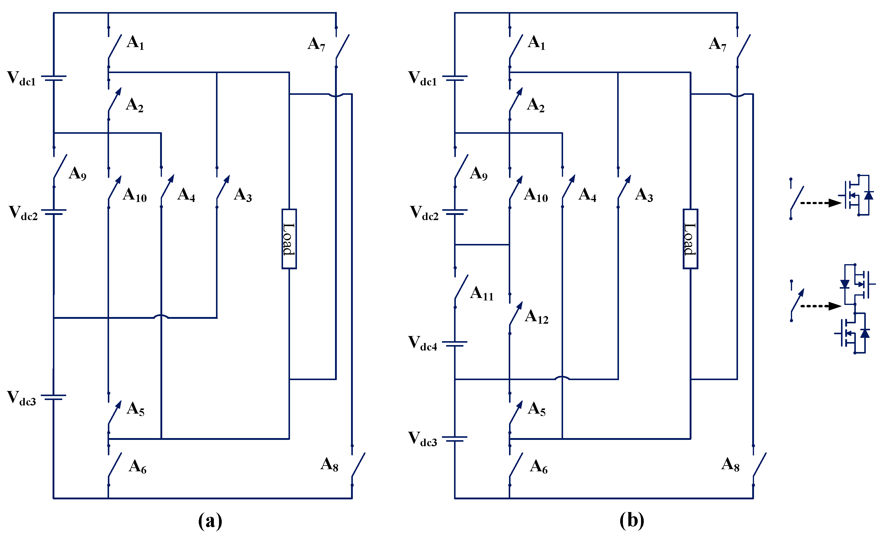
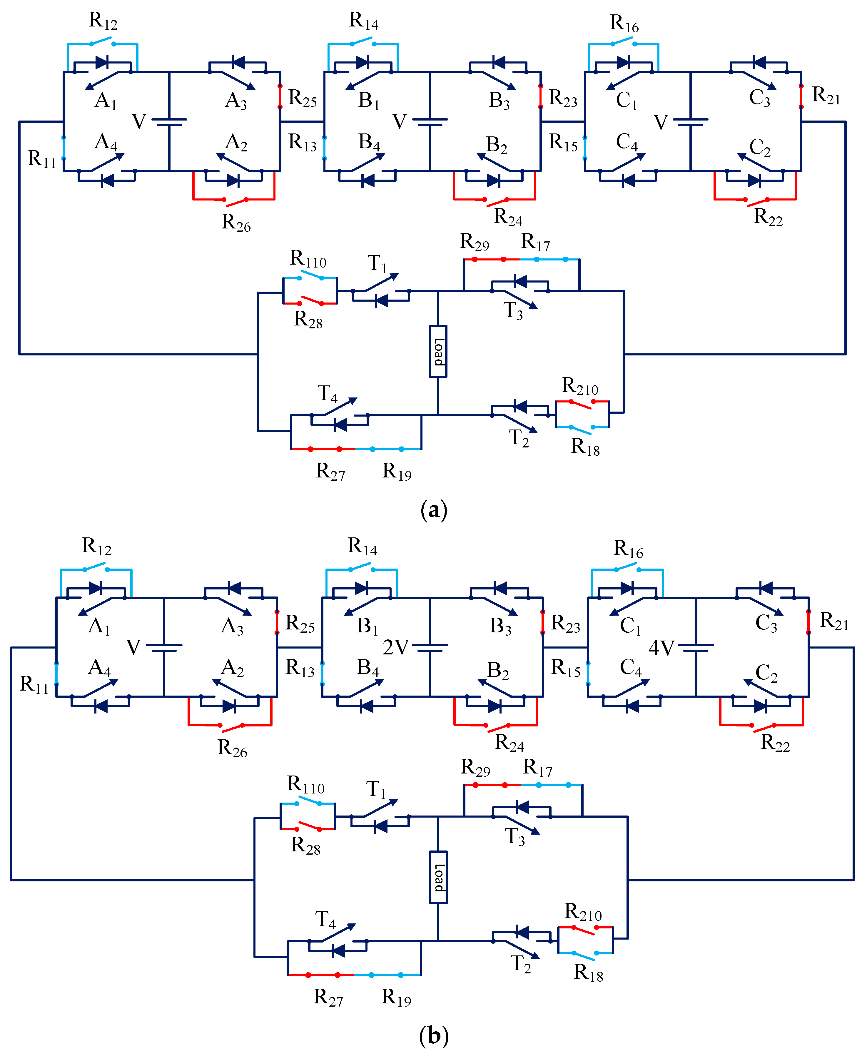
The authors of another study modified the CHB MLI and provided fault tolerance through their proposed scheme in [80]. The circuit of the single-phase seven-level FT MLI (TP47) (symmetric CHB, i.e., with the same sources) is shown in Figure 44a. The circuit of the single-phase fifteen-level FT MLI (TP48) (asymmetric CHB, i.e., with different sources) is shown in Figure 44b. This MLI topology consists of three CHB cells connected in cascade and one load-side H-bridge cell. The fault is removed by two relays. Each cell has one normally open (NO) and one normally closed (NC) conductor of each relay. The load-side H-bridge cell has two normally open (NO) and two normally closed (NC) conductors of each relay. The authors proposed an FT scheme for this MLI. The cascaded full-bridge CHB cells reconfigure to cascaded half-bridge CHB cells when the first fault occurs. The cascaded half-bridge CHB cells reconfigure to series-connected dc sources when a second fault occurs. This is the basic principle of this FT scheme. TP47 and TP48 use MB FT solution for fault tolerance.
The merits of the topology include the use of a smaller number of relays, low voltage stress exerted on healthy switches in case of fault, and utilization of all dc voltage sources under post-fault conditions. The limitations of the topology are as follows:
  • Load side CHB cannot be made FT with fewer devices [3].
  • Cannot generate pre-fault power after multiple-switch faults [35].

3.2.2. TP49

An FT structure and control scheme for CHB MLI are presented in [81]. The circuit diagram of the proposed single-phase seven-level FT MLI is shown in Figure 45. Each CHB module has four relays. The topology uses MB FT solution for fault tolerance. In any module’s switch fault (OC or SC fault), the proposed control scheme eliminates the defected module from the circuit. The MLI continues the power supply with reduced voltage levels, with the remaining healthy modules. The merit of the topology includes the ability to tolerate both OC and SC switch faults. The limitations of the topology are as follows:
  • High voltage stress is exerted on healthy switches in case of fault [80].
  • Higher conduction losses.
  • Higher cost.

3.2.3. TP50 and TP51

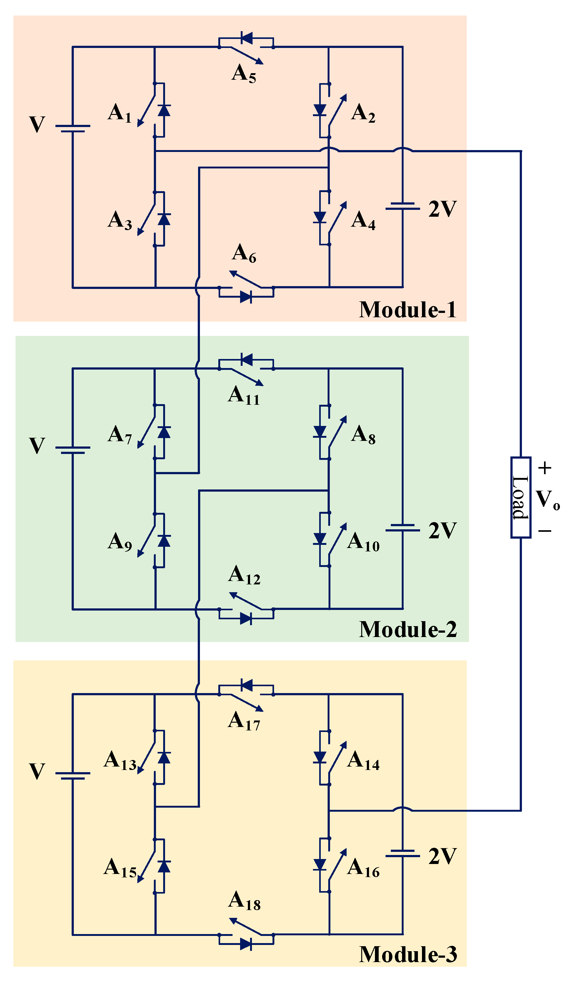
Other authors proposed a three-phase hybrid CHB FT MLI by adding an X-CHB inverter to the CHB inverter in [82]. The proposed three-phase inverter can generate an “N” number of levels. The circuit diagram of the proposed three-phase seven-level hybrid CHB inverter (TP50) is shown in Figure 46a. The circuit diagram of the proposed single-phase seven-level hybrid CHB inverter (TP51) is shown in Figure 46b. TP50 and TP51 use MB FT solution for fault tolerance. If a switch fault occurs in any H-bridge cell, the faulty H-bridge cell is bypassed and provides power from the remaining H-bridge cells and X-CHB cell. The proposed topology continues to deliver power at pre-fault voltage levels in case of OC or SC switch faults. It also provides self-balancing capacitor voltage. Battery energy storage systems (BESSs) and uninterrupted power systems are good examples of industrial applications that can utilize the topology. The merits of the topology include the ability to tolerate OC or SC faults and the ability to extend topology to an “N” number of levels. A higher device count is the limitation of the topology.

3.2.4. TP52

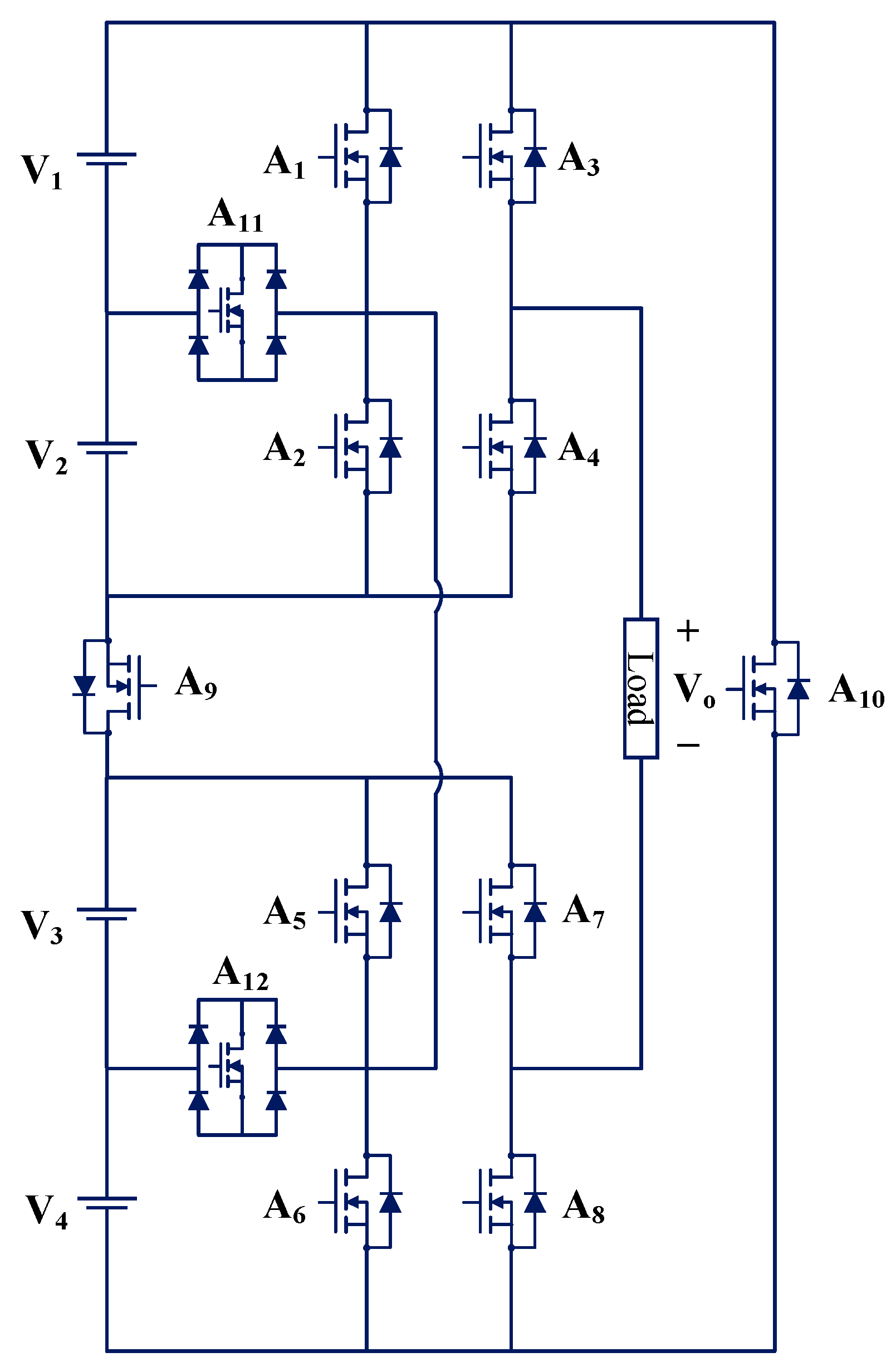
A single-phase thirteen-level FT MLI is proposed in [83], and it is shown in Figure 47. The topology consists of three modified CHB bridge modules. Each module comprises two DC sources and six unidirectional switches. One module always acts as a redundant module. Overall, the topology comprises six DC sources and eighteen unidirectional switches. The thirteen-level output is synthesized by two modules, whereas the faulty module is bypassed. The LS-SPWM scheme is used for creating the gating pulses in the topology. The topology uses the MB FT solution for fault tolerance. All the modules are equally used during normal operation. TP52 can tolerate single-switch OC and SC faults.

3.2.5. TP53

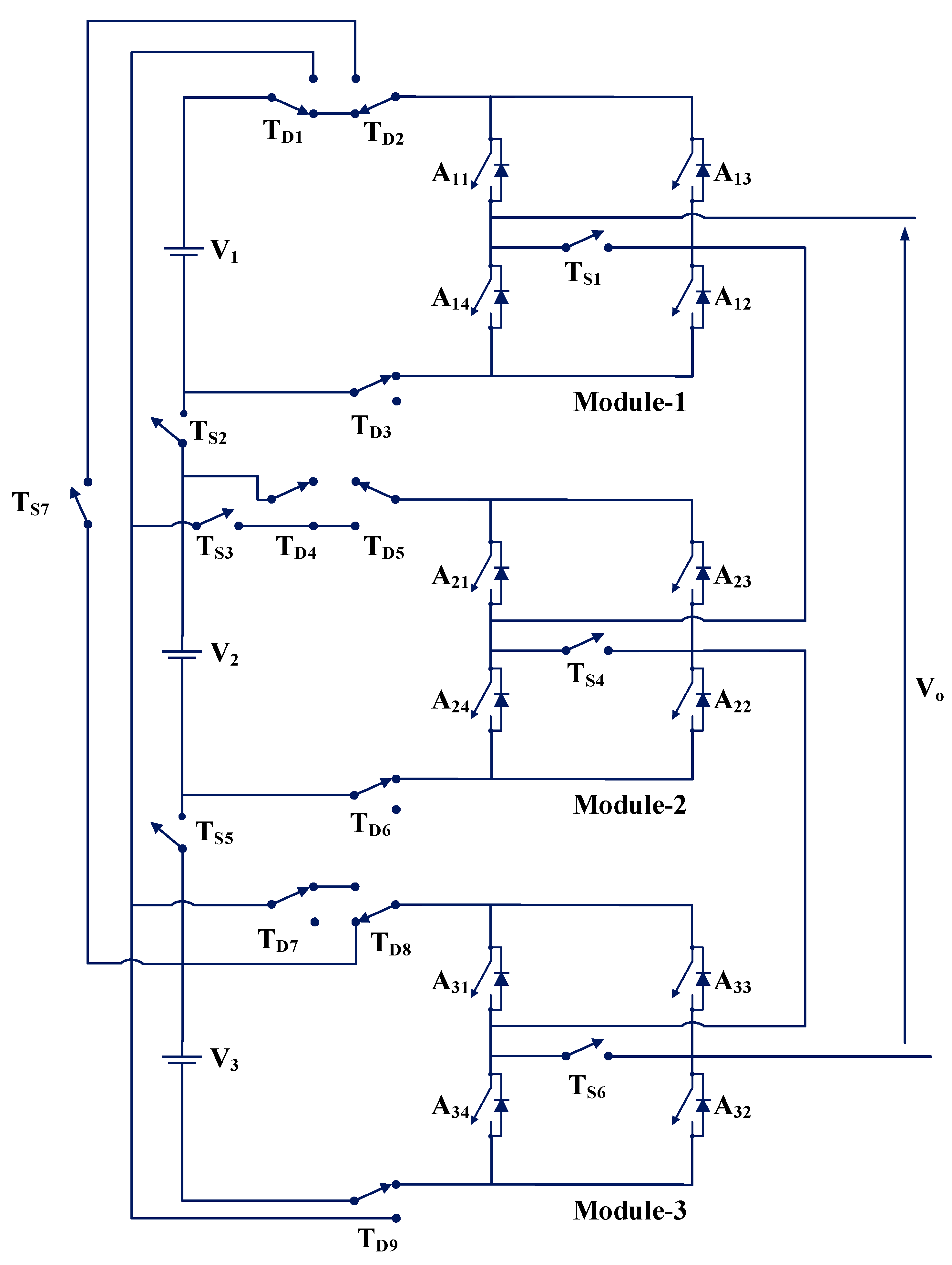
A single-phase seven-level FT MLI is proposed in [84], and it is shown in Figure 48. It comprises three DC sources, sixteen relays, and twelve unidirectional switches. During faulty operation, relays are used to reroute conducting paths. It is important to note that TS1 to TS7 are single-pole, single-throw (SP-ST) relays, and TD1 to TD9 are single-pole, double-throw (SP-DT) relays [84]. The PD-SPWM scheme is used for creating the gating pulses in the topology. The topology uses MB FT solution for fault tolerance. When one module is faulty, the faulty module is isolated, and the faulty module’s source is connected in series with one of the sources of healthy modules. If one module becomes faulty, the TP53 can continue to provide the same output voltage waveform and amplitude, as it did in the pre-fault operation. The use of a large number of relays is the drawback of this topology.

4. Comparison of Recently Developed Single-Phase FT MLI Topologies

In the previous section, several recently developed single-phase FT MLI topologies proposed in the literature were discussed. In this section, firstly, a comparison of these topologies based on comparative factors proposed in the literature is made. Finally, single-phase FT MLIs are compared based on proposed novel factors.
The topologies are compared based on the number of output voltage levels (X1), number of bidirectional switches (X2), number of DC supply (X3), number of capacitors (X4), total number of switches (IGBT or MOSFET devices) (X5), number of diodes (X6), number of fuses (X7), maximum number of switches to operate in the healthy condition (X8), maximum number of switches to operate in the faulty condition (X9), number of inductors (X10), number of relays (X11), and number of gate driver circuits (X12). It is assumed that a bidirectional switch (IGBT or MOSFET with four diodes) counts as a bidirectional switch (two IGBTs or two MOSFETs).
Single-phase FT MLI topologies are categorized into different groups according to the number of output voltage levels. The following factors are calculated for each topology.

4.1. Level to Switch Count Ratio (LSCR)

It is defined as the ratio of output voltage levels to the total switch (total IGBTs/MOSFETs) count. It was used for comparing MLIs in [85]. The higher value of LSCR implies better MLI topology than those with a lower LSCR value in terms of switch count. The LSCR is given as follows:
LSCR = X 1 X 5

4.2. Component Count to Level Ratio (CCLR)

It is defined as the ratio of total component counts to the output voltage levels. This factor is proposed in [86] for comparing MLIs. The lower value of CCLR implies better MLI topology than those with a higher CCLR value in terms of total component count. The CCLR is given as follows:
C C L R = X 3 + X 4 + X 5 + X 6 + X 7 + X 10 + X 11 + X 12 X 1
The inverse of the CCLR is used in this work. It represents the level to total component count ratio (LCCR). The higher value of the LCCR implies better MLI topology than those with a lower LCCR value in terms of total component count. The LCCR is given as follows:
L C C R = X 1 X 3 + X 4 + X 5 + X 6 + X 7 + X 10 + X 11 + X 12

4.3. Total Standing Voltage (TSV) and Cost Function (CF)

The TSV refers to the amount of voltage stress exerted on all power switches and power diodes. In mathematical terms, it is the sum of the maximum voltage that can be blocked by each power switch and power diode [87]. The TSV can be calculated as follows:
T S V = i = 1 P V P S i + t = 1 Q V P D t
where V P S i and V P D t are the magnitude of the maximum standing or blocking voltage for the ith power switch and tth power diode, respectively. Moreover, i = 1, 2, 3, …, P; and t = 1, 2, 3, …, Q. P and Q are the total number of power switches and power diodes, respectively, in the FT MLI.
The TSV per unit (TSVP.U.) can be calculated by taking the ratio of TSV to the maximum output voltage (Vomax) [88]:
T S V P . U . = T S V V o m a x
The TSV can be used to determine the ratings and costs of the power electronic devices that will be used in the topology, as well as the overall cost of the inverter circuit [89]. Devices with a lower voltage blocking capability will have a lower rating, which will result in a lower cost. Devices with a higher voltage blocking capability will have a higher rating, which will result in a higher cost. The TSV is an essential factor in reducing the cost of MLIs. A lower TSV results in a lower MLI cost, while a higher TSV results in a higher MLI cost. Hence, different power electronic devices in an MLI should be evaluated for voltage stress [88,90].
In general, the implementation feasibility of an MLI topology is approximated by its cost function (CF) [91]. The CF can be calculated in the following manner:
C F = X 3 + X 4 + X 5 + X 6 + X 7 + X 10 + X 11 + X 12 + µ × T S V P . U .
It should be noted that µ is the weighting coefficient for the TSV; µ can be chosen to be greater than unity when the TSV needs to be given more importance. When moderate attention is paid to TSV, µ between 0 and 1 is chosen. In this work, µ = 1.5 is selected for the first case, and µ = 0.5 is chosen for the second case [91].
The ratio of CF to the number of output voltage levels, denoted by CFLR, is calculated in this work. The lower value of CFLR implies cheaper MLI topology compared to those with higher CFLR values [91]. The CFLR is given as follows:
C F L R = C F   X 1
The inverse of CFLR is also used in this work. It represents the level to CF ratio (LCFR). The higher value of LCFR implies a cheaper MLI topology than those with a lower LCFR value. LCFR is given as follows:
L C F R = X 1   C F
Table 1 compares single-phase FT MLIs in terms of LSCR and LCCR. Different topologies are divided into six groups depending upon the number of output voltage levels. Group-I, Group-II, Group-III, Group-IV, Group-V, Group-VI, and Group-VII have 5-level, 7-level, 9-level, 11-level, 13-level, 15-level, and 17-level FT MLI topologies, respectively. In Group-I, topology TP44 is the best topology for a lower component count (higher LCCR or LSCR). In Group-II, topology TP34 is the best topology regarding a higher LSCR value or higher LCCR value. In Group-III, topology TP14 is the best topology regarding a higher LSCR value or higher LCCR value. In Group-V, TP13 and TP33B have the same LSCR value, but TP33B is best in terms of the LCCR value. In Group-VI, topology TP22 is the best topology regarding a higher LSCR value or higher LCCR value. In Group-VII, TP16 and TP25 have the same LSCR and LCCR values.
Table 2 compares single-phase FT MLIs based on modules in terms of LSCR and LCCR. Different topologies are divided into three groups depending on the number of output voltage levels. Group-VIII, Group-IX, and Group-X have 7-level, 13-level, and 15-level FT MLI topologies, respectively. In Group-VIII, topologies (TP49 and TP53) have higher and the same LSCR values. TP47 is the best topology in terms of a higher LCCR value.
The TSV, CF, and CFLR values were calculated for all FT MLI topologies. Table 3 compares single-phase FT MLIs in terms of TSV, CF, and CFLR. In Group-I, topology TP44 has the lowest CFLR value in the case of µ = 0.5, whereas TP35 has the lowest CFLR value in the case of µ = 1.5. In Group-II, topology TP34 has the lowest CFLR value in both cases, i.e., µ = 0.5 and µ = 1.5. In Group-III, topology TP14 has the lowest CFLR value in the case of µ = 0.5, whereas TP18 has the lowest CFLR value in the case of µ = 1.5. In Group-VI, topology TP22 has the lowest CFLR value in both cases, i.e., µ = 0.5 and µ = 1.5.
Table 4 compares single-phase FT MLIs in terms of TSV, CF, and CFLR. In Group-VIII, topology TP47 has the lowest CFLR value in the case of µ = 0.5, whereas TP49 has the lowest CFLR value in the case of µ = 1.5.

4.4. Fault Tolerance Factor and Complete Fault Tolerance Factor

The factors LSCR, LCCR, CFLR, and LCFR only measure the MLI’s cost and size by considering the number of components for generating “N” levels of the output waveform. These factors are good for comparing MLI topologies without fault tolerance capability. LSCR, LCCR, CFLR, and LCFR do not quantitatively measure an MLI’s fault tolerance capability. This work proposes a novel factor known as the fault tolerance factor (FTF) to measure the fault tolerance of an MLI quantitively. It can be calculated as follows:
F T F = 1 G k H k
where G is the total number of switching devices in the MLI; H is the available number of levels for a faulty switch to synthesize output voltage waveform; k is the switching device of the original topology; and k = 1, 2, 3, …, G. The higher value of FTF implies better FT MLI topology as compared to those that have a lower FTF value. FTF actually measures the fault tolerance of the MLI at the expense of the number of switches.
Let us understand with an example of a single-switch OC (SSOC) fault in a redundant leg-based MLI. For a topology (TP5) given in [34], FTF is calculated for faulty switches, taking one at a time. FTFO is FTF for MLI without extra hardware (without redundant leg), and FTFPF is FTF for an MLI with fault reconfiguration (after adding a redundant leg). It is noted that FTFO is only calculated for MLI topologies in which some additional hardware components are added. In the case of the IHR type of FT solution, FTF can be calculated only for post-fault conditions, as these topologies do not add any additional hardware components. The available number of levels for faulty switch A1, A2, A3, A4, B1, B2, B3, and B4 is 3, 0, 0, 3, 3, 0, 0, and 3, respectively, during the faulty condition. Here the total number of switches (G) in MLI (before adding the redundant leg) is 8.
F T F O = 1 G k = 1 , 2 , , 8 H k
F T F O = 1 8 H 1 + H 2 + H 3 + H 4 + H 5 + H 6 + H 7 + H 8
F T F O = 1 8 3 + 0 + 0 + 3 + 3 + 0 + 0 + 3 = 1.5
After adding a redundant leg to the main inverter (or original topology), the available number of levels for faulty switch A1, A2, A3, A4, B1, B2, B3, and B4 are 5, 5, 5, 5, 5, 5, 5, and 5, respectively, under post-fault condition. Here, the total number of switches (G) in MLI (after adding the redundant leg) is 14.
F T F P F = 1 G k = 1 , 2 , , 8 H k
F T F P F = 1 14 H 1 + H 2 + H 3 + H 4 + H 5 + H 6 + H 7 + H 8
F T F P F = 1 14 5 + 5 + 5 + 5 + 5 + 5 + 5 + 5 = 2.857
For the topology TP5, without extra hardware FTF (FTFO) and post-fault (or with reconfiguration) FTF (FTFPF) are 1.5 and 2.857, respectively. It means that MLI topology after adding the redundant leg becomes 90.47% more FT compared to the original (main inverter) MLI topology for SSOC faults.
The FTF can be calculated for single- and multiple-switch OC and SC faults. Multiple-switch faults can be for a pair, triplet, or quadruple of switches. Table 5 compares single-phase five-level FT MLIs based on the proposed novel factor, FTF for a SSOC fault. To compare FT MLI from its previous version (original topology), FTFO and FTFPF values can be compared. There is an improvement of 66.67% SSOC fault tolerance capability in the case of topology TP6 by adding a redundant leg. There is an improvement of 28.55% SSOC fault tolerance capability in the case of topology TP1 by switch addition. There is an improvement of 136.08% SSOC fault tolerance capability in the case of topology TP2 by switch addition. There is an improvement of 37.5% SSOC fault tolerance capability in the case of topology TP3 by switch addition. There is an improvement of 77.76% SSOC fault tolerance capability in the case of topology TP11 by adding a redundant leg.
The FTF only measures the FT capability of an MLI quantitatively and does not include total component counts or cost in consideration. Hence, it cannot be used alone to compare the different FT MLIs. Therefore, another parameter, known as the complete fault tolerance factor (CFTF), is proposed to compare the different FT MLIs. The CFTF is given as follows:
(i)
When TSV is not considered,
CFTF = LCCR + (FTFPF)SOCF + (FTFPF)MOCF + (FTFPF)SSCF + (FTFPF)MSCF
(ii)
When TSV is considered,
CFTF = LCFR + (FTFPF)SOCF + (FTFPF)MOCF + (FTFPF)SSCF + (FTFPF)MSCF
where LCCR is level to total component count ratio, LCFR is level to cost function ratio, (FTFPF)SOCF is FTF for single-switch OC (SSOC) fault, (FTFPF)MOCF is FTF for multiple-switch OC (MSOC) fault, (FTFPF)SSCF is FTF for single-switch SC (SSSC) fault, and (FTFPF)MSCF is FTF for multiple-switch SC (MSSC) fault.
CFTF provides a complete solution for comparing FT MLIs topologies in terms of fault tolerance and the total component count or cost quantitatively. CFTF includes fault-type (OC or SC) and fault-number (single or multiple) information to calculate the fault tolerance of an FT MLI. The higher value of CFTF implies better FT MLI topology (lower component count and higher FT capability) as compared to those that have a lower CFTF value.
Table 5 compares single-phase five-level FT MLI topologies for SSOC faults when TSV is not considered. It shows that TP11 is the best single-phase five-level FT MLI topology in terms of SSOC fault tolerance and the lower total component count or cost in Group-I by using the parameter (LCCR + FTFPF). Topology TP11, TP2, and TP12 are the best (higher LCCR + FTFPF value) FT MLI among LA, SA, and IHR type of FT MLI, respectively.
Table 6 shows the comparison of single-phase five-level FT MLI topologies for SSOC faults when the TSV factor is considered. It shows that TP11 is the best single-phase five-level FT MLI topology in both cases, i.e., µ = 0.5 and µ = 1.5, in terms of SSOC fault tolerance and lower cost in Group-I by using the parameter (LCFR + FTFPF). Topology TP11, TP23, and TP12 are the best (higher LCFR + FTFPF value) FT MLIs among LA, SA, and IHR types of FT MLI, respectively, in both cases, i.e., µ = 0.5 and µ = 1.5.
Only (FTFPF)SOCF is used in this work; the (FTFPF)MOCF, (FTFPF)SSCF, and (FTFPF)MSCF values are not calculated in this work and are left for future analysis. This will lead to more accurate results and provide the best FT MLI topologies in fault tolerance and cost. Including the LCFR factor in CFTF provides more realistic results than the LCCR factor by considering the TSV factor.
The evaluation of reliability can be carried out in a variety of ways. Markov chain theory (MCT) is a popular method to evaluate reliability. The reliability of TP42 is found to be higher than TP17 in [74], using MCT. It can be seen that the fault tolerance capability of TP42 is higher than TP17 in Table 5 and Table 6. The reliability of TP32 is found to be higher than TP17 in [64], using MCT. It can be seen that the fault tolerance capability of TP32 is higher than TP17 in Table 5 and Table 6. The reliability of TP19 is found to be higher than TP8 and TP9 in [54], using MCT. It can be seen that the fault tolerance capability of TP19 is higher than TP8 and TP9 from Table 5 and Table 6. Hence, the proposed factor (CFTF) verifies the effectiveness in evaluating fault tolerance. The proposed method provides approximately the same results as the MCT method. The proposed method uses the number of voltage levels and the component count or costs, whereas MCT uses the component failure rate to calculate reliability. The proposed method is less complex, more accurate, and easy to compare different FT MLIs. CFTF value gives information on component count or cost, as well as fault tolerance, whereas MCT gives only information on reliability or fault tolerance. The drawback of CFTF is that it does not provide reliability as a function of time because of the exclusion of the failure rate of the components.

5. Simulation and Experimental Results of a FT MLI

This paper performs and describes the FT operation of the FT MLI topology proposed in [34].
Only switch OC fault operation is analyzed in this work. The fuses were removed from the original topology because this work does not deal with SC faults. The topology is shown in Figure 49. The topology consists of the main inverter and the redundant leg.
The FT MLI topology consists of two dc sources (V1 = V2 = E), four clamping diodes, and fourteen switches (IGBTs). Out of fourteen switches, six switches were only utilized under faulty conditions. These six switches form a redundant leg in this FT MLI topology. This topology can generate a five-level output voltage waveform under healthy operation (or pre-fault condition).
The switching states of FT MLI under healthy operation are described in Table 7. The levels L1, L2, L3, L4, and L5 denote output voltage amplitude 2E, E, 0, −E, and −2E, respectively. There are two switching combinations for levels L2 and L4, three switching combinations for level L3, and one switching combination for levels L1 and L5.

5.1. Nearest Level Control

Switching loss, harmonics, and filter size are all impacted by modulation methods. A fundamental frequency switching scheme is employed in this work to control the FT MLI topology. The NLC-PWM scheme is employed in this work.
For higher output voltage applications, the NLC offers the advantage of reduced switching losses and minimal low-order harmonics [92]. In the NLC, a sinusoidal signal with fundamental frequency is utilized as a reference signal, and it is compared to other carrier signals (Q1 to Qn) to implement each switching state. A sampled waveform can be obtained in NLC by comparing a reference sinusoidal waveform with the desired output waveform. Between the two levels, a 0.5Vdc DC loss error is generally maintained [38]. The waveform generated is then rounded off to the nearest level and compared appropriately to the switching states in Table 7 to generate gate signals for the respective IGBTs [92]. Figure 50 [93] shows a comparison of the reference sine wave with the desired output voltage levels. The NLC’s working principle is depicted in Figure 51 [92].
For generating N-level (Nlevel) output voltage waveform, the carrier signal is given by Table 8 [38]. Here u is given by
u = N l e v e l 1 2
In the case of conventional NLC, the switching angle is calculated as follows [94]:
θ i = M sin 1 i 0.5 u
where i = 1, 2, 3, …, u; and M is referred to as modulation index and is stated as follows [92,95]:
M = V r e f V o = V r e f N l e v e l 1 2   V d c = 2 V r e f N l e v e l 1 V d c = V r e f u V d c
The modulation scheme is altered whenever an OC switch fault is detected to generate new switching angles [39]. This operation ensures continuous operation after a fault. The redundant leg is used for providing a conduction path in the case of a switch fault. Table 9 depicts the status of output voltage waveform levels under healthy, faulty, and post-fault conditions for all single switches and two multiple-switch pairs.

5.2. Simulation Results and Discussion

In the case of the FT MLI topology, the output voltage and load current for the (RL) load during the pre-fault, fault, and post-fault period are simulated by using MATLAB/Simulink® 2018b environment. The OC fault is imitated by disconnecting the specified switching device’s gating pulse. NLC-PWM is utilized to generate the gate triggering pulses to the switches of the FT MLI. Three different cases were chosen to evaluate the performance of FT MLI under OC fault. The three different cases include single device fault, two device faults in the same leg, and two device faults in different legs. In Table 10, all the parameters of the device that were used in the simulation are listed.
Based on simulation results for the FT MLI for RL load, Figure 52 illustrates the output voltage and load current for three different operating conditions, i.e., pre-fault state, faulty state, and post-fault state. An OC fault is simulated by removing gate pulses of the faulty switching device at a time of 0.442 s to know the voltage level status during an OC fault. The instance of fault (FI) means the instant at which OC fault occurs. The instance of reconfiguration (RI) represents the instant at which reconfiguration operation is made to provide fault tolerance to an FT MLI. At 0.518 s, the reconfiguration operation takes place as marked with RI. Redundant leg switches are used during reconfiguration to provide different conduction paths in order to generate voltage levels that would be lost in the event of an OC fault. This FT MLI topology’s operation preserves original output voltage levels by utilizing switches present in the redundant leg.

5.2.1. Single-Switch OC Fault

The simulation results of a single-switch OC fault are shown in Figure 52a. Single-switch OC fault in switch A1 shows the loss of L1 voltage level. This is because of the loss of connection between point P and point A, as shown in Figure 49. A different conduction path may be provided during reconfiguration operation, using redundant leg switches R1, R2, and R5 to preserve the L1 voltage level. Consequently, the voltage waveforms remain unchanged before and after the OC fault. Similarly, Figure 52b–h show OC fault simulation results for switch A2, A3, A4, B1, B2, B3, and B4, respectively.

5.2.2. Multiple-Switch OC Fault

The simulation result of multiple-switch OC faults in the same leg is shown in Figure 52i. The loss of the output voltage levels L1 and L5 is caused by two switch OC faults in switches A1 and A4. A different conduction path may be provided during reconfiguration operation, using redundant leg switches R1, R2, and R5 to preserve the L1 voltage level and R1, R3, and R4 to preserve the L5 voltage level.
The simulation result of multiple-switch OC faults in different legs is shown in Figure 52j. The loss of the output voltage levels L4 and L5 is caused by two switch OC faults in switches A4 and B1. A different conduction path may be provided during reconfiguration operation by using redundant leg switches R3, R4, and R6 to preserve the L4 voltage level and R1, R3, and R4 to preserve the L5 voltage level.

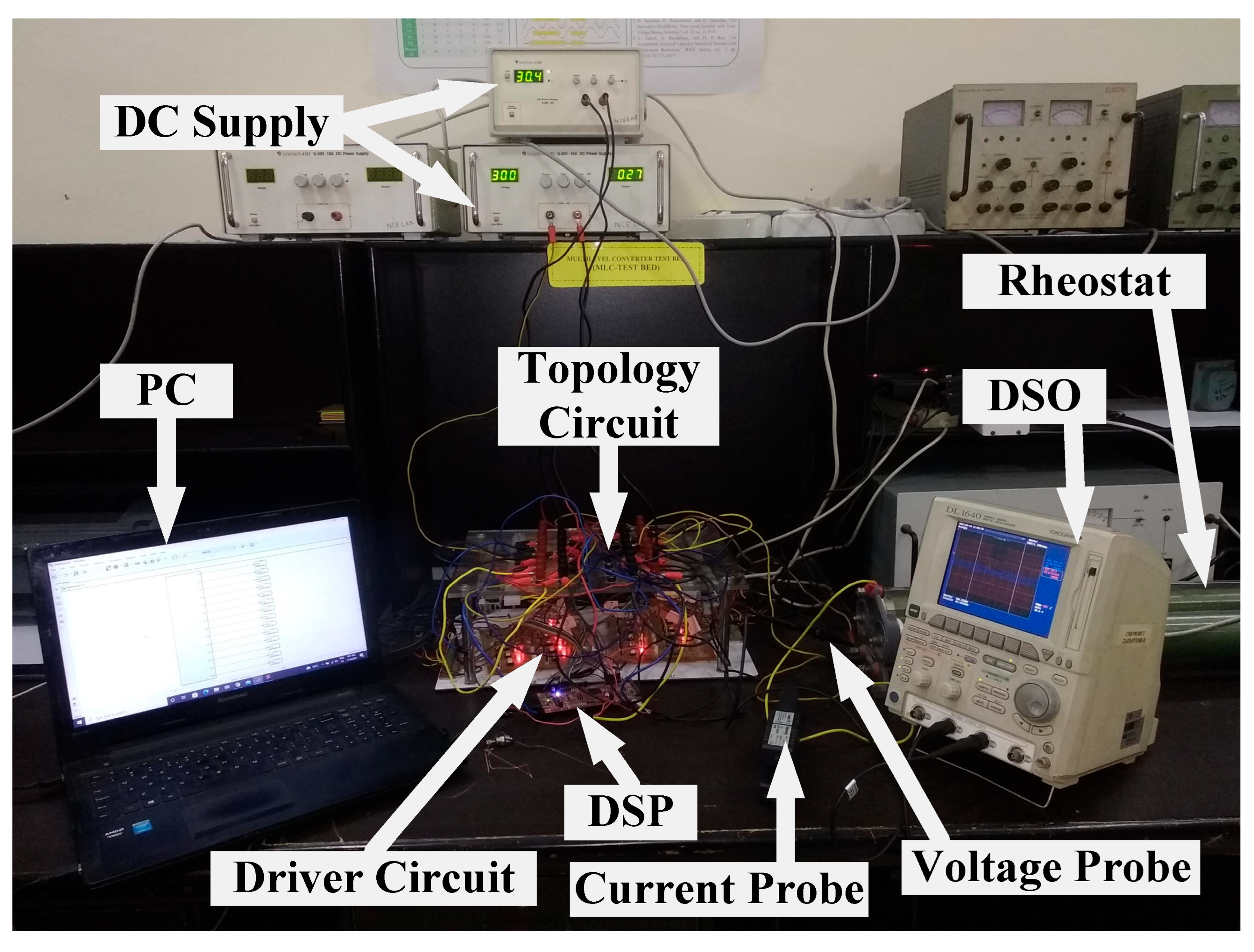
5.3. Experimental Results and Discussion

A variety of experimental tests are conducted to examine the feasibility and robustness of the five-level FT MLI for OC faults in switching device(s). The experiment is carried out on a purely resistive (R) load. The FT MLI topology is constructed with fourteen IGBTs (FGA25N120) which act as switching devices. A gate driver circuit based on the TOSHIBA TLP-250 optocoupler is used for giving gating signals to individual IGBTs. In accordance with the NLC-PWM scheme, the gating pulses are generated by a digital signal processor (DSP) TMS320F28379D. In order to record different output waveforms, the scope coder YOKOGAWA DL1640 is used. A list of the experimental parameters utilized for performing studies on different switch faults on the FT MLI can be found in Table 11. Figure 53 shows an illustration of the experimental setup that was used in this work.

5.3.1. Single-Switch OC Fault

Figure 54a illustrates the experimental results obtained under the switch A1 OC fault of the FT MLI. Under normal or healthy operating conditions, −2E, −E, 0, E, and 2E output voltage levels are generated by using P9, P7, P4, P2, and P1, respectively. Upon reviewing Table 9, it can be seen that the OC fault on switch A1 results in the loss of 2E voltage level. The FI mark shows the failure of switch A1. In the reconfiguration operation, the switching path P1 is replaced by the path through redundant leg switches R1, R2, and R5. The RI mark represents the turn-on of redundant switches. It is important to note that, in this instance, the post-fault voltage is able to regain its level and preserve the level of voltage prior to the fault. Similarly, Figure 54b–h show OC fault experimental results for switch A2, A3, A4, B1, B2, B3, and B4, respectively.

5.3.2. Multiple-Switch OC Fault

The experimental result of multiple-switch OC faults in the same leg is shown in Figure 54i. Two switches’ OC fault in switches A1 and A4 displays loss of L1 and L5 voltage levels that are available under healthy operation, as described in Table 9. The missing voltage levels for the switches A1 and A4 OC faults can also be seen in Table 7. FI indicates that switches A1 and A4 have failed. The next is the reconfiguration stage, in which the redundant leg’s switches (R1, R2, and R5 to preserve the L1 voltage level and R1, R3, and R4 to preserve the L5 voltage level) are activated accordingly in order to produce the five-level voltage waveform at the output. RI demonstrates that redundant switches are being turned ON.
The experimental result of multiple-switch OC faults in the different legs is shown in Figure 54j. Two switches’ OC fault in switches A4 and B1 displays loss of L4 and L5 voltage levels that are available under healthy operation, as described in Table 9. The missing voltage levels for the OC faults of switches A4 and B1 can also be seen in Table 7. FI indicates that switches A4 and B1 have failed. The next is the reconfiguration stage, in which the redundant leg’s switches (R3, R4, and R6 to preserve the L4 voltage level and R1, R3, and R4 to preserve the L5 voltage level) are activated accordingly in order to produce the five-level voltage waveform at the output. RI demonstrates that redundant switches are being turned ON.
Thus, it can be observed from the simulation, and experimental results that the five-level FT MLI topology is capable of delivering the full voltage levels at rated output power under SSOC fault, MSOC fault in the same leg, and MSOC faults in the different legs.

6. Conclusions

This paper provides a comprehensive survey of FT solutions used in MLI, as reported in the literature. Various FT solutions are explained, along with their merits and demerits. Furthermore, a comprehensive review of single-phase FT MLI topologies provides a clear picture of the current research status. There is a growing interest in fault diagnosis and fault tolerance in power electronic systems. To ensure the reliability of MLIs, their application in MLIs is of great importance. FT MLI topologies are reviewed based on their constructional features, merits, and limitations. A comparison between different proposed FT MLI topologies in terms of LSCR, LCCR, CFLR, and LCFR parameters is summarized in the tables. New comparative factors—FTF and CFTF—were introduced to compare FT MLI topologies more effectively. An FTF-and-CFTF-factors-based comparison is validated with the results from the MCT method to evaluate fault tolerance or reliability. A comparative analysis is presented to demonstrate the utility of the proposed parameters for comparing FT MLIs, allowing for a future evaluation of newer FT MLI topologies easier. The existing redundant leg-based single-phase five-level FT MLI topology is analyzed to show the FT operation in case of single- and multiple-switch OC faults. The pre-fault, during fault, and post-fault operation of this FT MLI topology are demonstrated with the help of simulation and experimental results. Based on the research, the following limitations are identified:
  • There are relatively few single-phase FT MLI topologies designed to handle multiple-switch OC and/or SC faults, owing to the fact that a majority of single-phase FT MLI topologies are only appropriate for single-switch OC and/or SC faults. The development of single-phase FT MLI topologies capable of handling multiple-switch faults is an area that requires further study.
  • It has been observed that redundant switches or redundant legs of FT MLIs have zero percent utilization under normal or healthy conditions. Hence, redundant switches remain non-operational under healthy conditions and increase the MLI cost. The development of FT MLI topologies where all switches operate under healthy conditions is an area that requires further investigation.
  • Redundant switches or redundant legs of FT MLIs only operate under faulty condition. If redundant switches were to participate during times of overload current under healthy conditions, the thermal stress on the main inverter’s switches would be significantly reduced. Hence, the FT MLI topology would be more reliable and longer lasting. Few works in the literature analyzed the overload capability characteristics of redundant-leg or redundant-switch-based FT MLIs. Further investigation can be performed on this type of MLIs.
  • Some FT MLI topologies are unable to preserve output rated voltage post-fault. Hence, topologies use a step-up transformer to maintain the output rated voltage. This will increase the cost and size of the system. The development of FT MLI topologies where output rated voltage can be achieved post-fault under the maximum number of switch fault occurrences is an area that requires further study.
  • The development of FT MLI topologies where output power and efficiency can be achieved post-fault similar to pre-fault condition is an area that requires further investigation.
  • Most of the FT MLI topologies in the literature focused on the switch fault. Very few works in the literature analyzed the capacitor and DC source failures in FT MLIs. The design of new FT MLI topologies that ensure operational continuity in the event of a capacitor and/or source failure requires further investigation.
  • Few FT MLIs that can be extended for the “N” number of voltage levels are reported in the literature. New FT MLI topologies that can be extended to higher voltage levels for high-voltage applications require further investigation.

Author Contributions

Conceptualization, H.R., M.T. and A.S.; methodology, H.R., M.T. and A.S.; validation, H.R., M.T. and A.S.; formal analysis, H.R., M.T. and A.S.; investigation, H.R., M.T. and A.S.; resources M.T. and A.S.; writing—original draft preparation, H.R., M.T. and A.S.; writing—review and editing, W.A., M.A.H. and S.M.B.; supervision, M.T. and A.S.; project administration, M.T. and W.A.; funding acquisition, M.T. and W.A. All authors have read and agreed to the published version of the manuscript.

Funding

The authors extend their appreciation to the Deputyship of Research Innovation, Ministry of Education in Saudi Arabia, for funding this research work through project number “375213500”.

Acknowledgments

The authors acknowledge the technical support provided by the Hardware-In-the-Loop (HIL) lab, Department of Electrical Engineering, ZHCET, Aligarh Muslim University, Aligarh, India.

Conflicts of Interest

The authors declare no conflict of interest.

References

  1. Salem, A.; Van Khang, H.; Robbersmyr, K.G.; Norambuena, M.; Rodriguez, J. Voltage Source Multilevel Inverters with Reduced Device Count: Topological Review and Novel Comparative Factors. IEEE Trans. Power Electron. 2021, 36, 2720–2747. [Google Scholar] [CrossRef]
  2. Kouro, S.; Malinowski, M.; Gopakumar, K.; Pou, J.; Franquelo, L.G.; Wu, B.; Rodriguez, J.; Perez, M.A.; Leon, J.I. Recent Advances and Industrial Applications of Multilevel Converters. IEEE Trans. Ind. Electron. 2010, 57, 2553–2580. [Google Scholar] [CrossRef]
  3. Nistane, T.J.; Sahu, L.K.; Jalhotra, M.; Gautam, S.P. Single and multiple switch fault-tolerance capabilities in a hybrid five-level inverter topology. IET Power Electron. 2020, 13, 1257–1266. [Google Scholar] [CrossRef]
  4. Bana, P.R.; Panda, K.P.; Naayagi, R.T.; Siano, P.; Panda, G. Recently Developed Reduced Switch Multilevel Inverter for Renewable Energy Integration and Drives Application: Topologies, Comprehensive Analysis and Comparative Evaluation. IEEE Access 2019, 7, 54888–54909. [Google Scholar] [CrossRef]
  5. Daher, S.; Schmid, J.; Antunes, F.L.M. Multilevel Inverter Topologies for Stand-Alone PV Systems. IEEE Trans. Ind. Electron. 2008, 55, 2703–2712. [Google Scholar] [CrossRef]
  6. Xiao, B.; Hang, L.; Mei, J.; Riley, C.; Tolbert, L.M.; Ozpineci, B. Modular Cascaded H-Bridge Multilevel PV Inverter with Distributed MPPT for Grid-Connected Applications. IEEE Trans. Ind. Appl. 2015, 51, 1722–1731. [Google Scholar] [CrossRef]
  7. Zhang, X.; Zhao, T.; Mao, W.; Tan, D.; Chang, L. Multilevel Inverters for Grid-Connected Photovoltaic Applications: Examining Emerging Trends. IEEE Power Electron. Mag. 2018, 5, 32–41. [Google Scholar] [CrossRef]
  8. Madhukar Rao, A.; Sivakumar, K. A Fault-Tolerant Single-Phase Five-Level Inverter for Grid-Independent PV Systems. IEEE Trans. Ind. Electron. 2015, 62, 7569–7577. [Google Scholar] [CrossRef]
  9. Joseph, A.; Chelliah, T.R. A Review of Power Electronic Converters for Variable Speed Pumped Storage Plants: Configurations, Operational Challenges, and Future Scopes. IEEE J. Emerg. Sel. Top. Power Electron. 2018, 6, 103–119. [Google Scholar] [CrossRef]
  10. Hoon, Y.; Radzi, M.A.M.; Hassan, M.K.; Mailah, N.F. Operation of Three-Level Inverter-Based Shunt Active Power Filter Under Nonideal Grid Voltage Conditions with Dual Fundamental Component Extraction. IEEE Trans. Power Electron. 2018, 33, 7558–7570. [Google Scholar] [CrossRef]
  11. Varschavsky, A.; Dixon, J.; Rotella, M.; Moran, L. Cascaded Nine-Level Inverter for Hybrid-Series Active Power Filter, Using Industrial Controller. IEEE Trans. Ind. Electron. 2010, 57, 2761–2767. [Google Scholar] [CrossRef]
  12. Soto, D.; Green, T. A comparison of high-power converter topologies for the implementation of FACTS controllers. IEEE Trans. Ind. Electron. 2002, 49, 1072–1080. [Google Scholar] [CrossRef] [Green Version]
  13. Nair, R.N.; Gopakumar, K.; Franquelo, L.G. A Very High Resolution Stacked Multilevel Inverter Topology for Adjustable Speed Drives. IEEE Trans. Ind. Electron. 2018, 65, 2049–2056. [Google Scholar] [CrossRef]
  14. Ghat, M.B.; Shukla, A. A New H-Bridge Hybrid Modular Converter (HBHMC) for HVDC Application: Operating Modes, Control, and Voltage Balancing. IEEE Trans. Power Electron. 2018, 33, 6537–6554. [Google Scholar] [CrossRef]
  15. Jung, J.-J.; Cui, S.; Lee, J.-H.; Sul, S.-K. A New Topology of Multilevel VSC Converter for a Hybrid HVDC Transmission System. IEEE Trans. Power Electron. 2017, 32, 4199–4209. [Google Scholar] [CrossRef]
  16. El-Hosainy, A.; Hamed, H.A.; Azazi, H.Z.; El-Kholy, E. A review of multilevel inverter topologies, control techniques, and applications. In Proceedings of the 2017 Nineteenth International Middle East Power Systems Conference (MEPCON), Cairo, Egypt, 19–21 December 2017; pp. 1265–1275. [Google Scholar] [CrossRef]
  17. Rodriguez, J.; Lai, J.-S.; Peng, F.Z. Multilevel inverters: A survey of topologies, controls, and applications. IEEE Trans. Ind. Electron. 2002, 49, 724–738. [Google Scholar] [CrossRef] [Green Version]
  18. Franquelo, L.G.; Rodriguez, J.; Leon, J.I.; Kouro, S.; Portillo, R.; Prats, M.A. The age of multilevel converters arrives. IEEE Ind. Electron. Mag. 2008, 2, 28–39. [Google Scholar] [CrossRef] [Green Version]
  19. Vijeh, M.; Rezanejad, M.; Samadaei, E.; Bertilsson, K. A General Review of Multilevel Inverters Based on Main Submodules: Structural Point of View. IEEE Trans. Power Electron. 2019, 34, 9479–9502. [Google Scholar] [CrossRef]
  20. Debnath, S.; Qin, J.; Bahrani, B.; Saeedifard, M.; Barbosa, P. Operation, Control, and Applications of the Modular Multilevel Converter: A Review. IEEE Trans. Power Electron. 2015, 30, 37–53. [Google Scholar] [CrossRef]
  21. Choi, U.-M.; Blaabjerg, F.; Lee, K.-B. Study and Handling Methods of Power IGBT Module Failures in Power Electronic Converter Systems. IEEE Trans. Power Electron. 2015, 30, 2517–2533. [Google Scholar] [CrossRef]
  22. Kumar, G.K.; Elangovan, D. Review on fault-diagnosis and fault-tolerance for DC–DC converters. IET Power Electron. 2020, 13, 1–13. [Google Scholar] [CrossRef]
  23. Dewangan, N.K.; Prakash, T.; Tandekar, J.K.; Gupta, K.K. Open-circuit fault-tolerance in multilevel inverters with reduced component count. Electr. Eng. 2020, 102, 409–419. [Google Scholar] [CrossRef]
  24. Gupta, K.K.; Ranjan, A.; Bhatnagar, P.; Sahu, L.K.; Jain, S. Multilevel Inverter Topologies with Reduced Device Count: A Review. IEEE Trans. Power Electron. 2016, 31, 135–151. [Google Scholar] [CrossRef]
  25. Krishnachaitanya, D.; Chitra, A. Quantitative Analysis of Asymmetric Multilevel Inverters with Reduced Device Count From Reliability and Cost Function Perspective—A Review. IEEE Trans. Power Electron. 2021, 36, 11068–11086. [Google Scholar] [CrossRef]
  26. Omer, P.; Kumar, J.; Surjan, B.S. A Review on Reduced Switch Count Multilevel Inverter Topologies. IEEE Access 2020, 8, 22281–22302. [Google Scholar] [CrossRef]
  27. Prabaharan, N.; Palanisamy, K. A comprehensive review on reduced switch multilevel inverter topologies, modulation techniques and applications. Renew. Sustain. Energy Rev. 2017, 76, 1248–1282. [Google Scholar] [CrossRef]
  28. Dewangan, N.K.; Gupta, S.; Gupta, K.K. Approach to synthesis of fault tolerant reduced device count multilevel inverters (FT RDC MLIs). IET Power Electron. 2019, 12, 476–482. [Google Scholar] [CrossRef]
  29. Firdous, Z.; Rehman, H.; Tariq, M.; Sarwar, A. Investigation of Fault-Tolerant Capabilities of a Reduced Device Multilevel Inverter. In Proceedings of the 2022 2nd International Conference on Emerging Frontiers in Electrical and Electronic Technologies (ICEFEET), Patna, India, 24–25 June 2022; pp. 1–5. [Google Scholar] [CrossRef]
  30. Zhang, W.; Xu, D.; Enjeti, P.N.; Li, H.; Hawke, J.T.; Krishnamoorthy, H.S. Survey on Fault-Tolerant Techniques for Power Electronic Converters. IEEE Trans. Power Electron. 2014, 29, 6319–6331. [Google Scholar] [CrossRef]
  31. Gautam, S.P.; Kumar, L.; Gupta, S.; Agrawal, N. A Single-Phase Five-Level Inverter Topology with Switch Fault-Tolerance Capabilities. IEEE Trans. Ind. Electron. 2017, 64, 2004–2014. [Google Scholar] [CrossRef]
  32. Aleenejad, M.; Jafarishiadeh, S.; Mahmoudi, H.; Ahmadi, R. Reduced number of auxiliary H-bridge power cells for post-fault operation of three phase cascaded H-bridge inverter. IET Power Electron. 2019, 12, 2923–2931. [Google Scholar] [CrossRef]
  33. Lezana, P.; Pou, J.; Meynard, T.A.; Rodriguez, J.; Ceballos, S.; Richardeau, F. Survey on Fault Operation on Multilevel Inverters. IEEE Trans. Ind. Electron. 2010, 57, 2207–2218. [Google Scholar] [CrossRef] [Green Version]
  34. Aly, M.; Ahmed, E.M.; Shoyama, M. A New Single-Phase Five-Level Inverter Topology for Single and Multiple Switches Fault Tolerance. IEEE Trans. Power Electron. 2018, 33, 9198–9208. [Google Scholar] [CrossRef]
  35. Chappa, A.; Gupta, S.; Sahu, L.K.; Gupta, K.K. A Fault-Tolerant Multilevel Inverter Topology with Preserved Output Power and Voltage Levels Under Pre- and Postfault Operation. IEEE Trans. Ind. Electron. 2021, 68, 5756–5764. [Google Scholar] [CrossRef]
  36. Katebi, R.; He, J.; Weise, N. Investigation of Fault-Tolerant Capabilities in an Advanced Three-Level Active T-Type Converter. IEEE J. Emerg. Sel. Top. Power Electron. 2019, 7, 446–457. [Google Scholar] [CrossRef] [Green Version]
  37. Dewangan, N.K.; Tailor, T.K.; Agrawal, R.; Bhatnagar, P.; Gupta, K.K. A multilevel inverter structure with open circuit fault-tolerant capability. Electr. Eng. 2021, 103, 1613–1628. [Google Scholar] [CrossRef]
  38. Asif, M.; Tariq, M.; Sarwar, A.; Hussan, R.; Ahmad, S.; Mihet-Popa, L.; Mohamed, A.S.N. A Robust Multilevel Inverter Topology for Operation under Fault Conditions. Electronics 2021, 10, 3099. [Google Scholar] [CrossRef]
  39. Sarwar, M.I.; Sarwar, A.; Farooqui, S.A.; Tariq, M.; Fahad, M.; Beig, A.R.; Alamri, B. A Hybrid Nearest Level Combined with PWM Control Strategy: Analysis and Implementation on Cascaded H-Bridge Multilevel Inverter and its Fault Tolerant Topology. IEEE Access 2021, 9, 44266–44282. [Google Scholar] [CrossRef]
  40. Chappa, A.; Gupta, S.; Sahu, L.K.; Gupta, K.K. Resilient multilevel inverter topology with improved reliability. IET Power Electron. 2020, 13, 3384–3395. [Google Scholar] [CrossRef]
  41. Jalhotra, M.; Kumar, L.; Gautam, S.P.; Gupta, S. Development of fault-tolerant MLI topology. IET Power Electron. 2018, 11, 1416–1424. [Google Scholar] [CrossRef]
  42. Peddapati, S.; Prasadarao, K.V.S. A New Fault-Tolerant Multilevel Inverter Structure with Reduced Device Count and Low Total Standing Voltage. IEEE Trans. Power Electron. 2022, 37, 8333–8344. [Google Scholar] [CrossRef]
  43. Mirafzal, B. Survey of Fault-Tolerance Techniques for Three-Phase Voltage Source Inverters. IEEE Trans. Ind. Electron. 2014, 61, 5192–5202. [Google Scholar] [CrossRef]
  44. Correa, P.; Pacas, M.; Rodriguez, J. Modulation Strategies for Fault-Tolerant Operation of H-Bridge Multilevel Inverters. In Proceedings of the 2006 IEEE International Symposium on Industrial Electronics, Montreal, QC, Canada, 9–13 July 2006; pp. 1589–1594. [Google Scholar] [CrossRef]
  45. Choi, U.-M.; Blaabjerg, F. A novel active T-type three-level converter with open-circuit fault-tolerant control. In Proceedings of the 2015 IEEE Energy Conversion Congress and Exposition (ECCE), Montreal, QC, Canada, 20–24 September 2015; pp. 4765–4772. [Google Scholar] [CrossRef]
  46. Sahoo, M.; Keerthipati, S. Fault tolerant three-level boost inverter with reduced source and LC count. IET Power Electron. 2018, 11, 399–405. [Google Scholar] [CrossRef]
  47. Do, D.-T.; Nguyen, M.-K.; Quach, T.-H.; Tran, V.-T.; Blaabjerg, F.; Vilathgamuwa, D.M. A PWM Scheme for a Fault-Tolerant Three-Level Quasi-Switched Boost T-Type Inverter. IEEE J. Emerg. Sel. Top. Power Electron. 2020, 8, 3029–3040. [Google Scholar] [CrossRef] [Green Version]
  48. Kumar, D.; Nema, R.K.; Gupta, S. Investigation of fault-tolerant capabilities of some recent multilevel inverter topologies. Int. J. Electron. 2021, 108, 1957–1976. [Google Scholar] [CrossRef]
  49. Rehman, H.; Iqbal, H.; Tariq, M.; Sarwar, A.; Sarfraz, M.; Gupta, G.M.; Maswood, A.I. Fault Tolerant Operation in Multilevel Inverter for More Electric Aircraft. In Proceedings of the 2022 2nd International Conference on Emerging Frontiers in Electrical and Electronic Technologies (ICEFEET), Patna, India, 24–25 June 2022; pp. 1–6. [Google Scholar] [CrossRef]
  50. Sadanala, C.; Pattnaik, S.; Singh, V.P. Fault tolerant architecture of an efficient five-level multilevel inverter with overload capability characteristics. IET Power Electron. 2020, 13, 368–376. [Google Scholar] [CrossRef]
  51. Jalhotra, M.; Sahu, L.K.; Gupta, S.; Gautam, S.P. Highly Resilient Fault-Tolerant Topology of Single-Phase Multilevel Inverter. IEEE J. Emerg. Sel. Top. Power Electron. 2021, 9, 1915–1922. [Google Scholar] [CrossRef]
  52. Siddique, M.D.; Rawa, M.; Mekhilef, S.; Shah, N.M. A new cascaded asymmetrical multilevel inverter based on switched dc voltage sources. Int. J. Electr. Power Energy Syst. 2021, 128, 106730. [Google Scholar] [CrossRef]
  53. Prasadarao, K.V.S.; Peddapati, S.; Naresh, S. A New Fault-Tolerant MLI—Investigating Its Skipped Level Performance. IEEE Trans. Ind. Electron. 2022, 69, 1432–1442. [Google Scholar] [CrossRef]
  54. Saketi, S.K.; Chaturvedi, P.; Yadeo, D.; Atkar, D. Loss study and reliability analysis of a new reconfigurable fault-tolerant multilevel inverter topology. IET Power Electron. 2020, 13, 4291–4303. [Google Scholar] [CrossRef]
  55. Reddy, K.N.; Pradabane, S. Modified H-bridge inverter based fault-tolerant multilevel topology for open-end winding induction motor drive. IET Power Electron. 2019, 12, 2810–2820. [Google Scholar] [CrossRef]
  56. Fahad, M.; Tariq, M.; Sarwar, A.; Modabbir, M.; Zaid, M.; Satpathi, K.; Hussan, R.; Tayyab, M.; Alamri, B.; Alahmadi, A. Asymmetric Multilevel Inverter Topology and Its Fault Management Strategy for High-Reliability Applications. Energies 2021, 14, 4302. [Google Scholar] [CrossRef]
  57. Fahad, M.; Alsultan, M.; Ahmad, S.; Sarwar, A.; Tariq, M.; Khan, I.A. Reliability Analysis and Fault-Tolerant Operation in a Multilevel Inverter for Industrial Application. Electronics 2021, 11, 98. [Google Scholar] [CrossRef]
  58. Maddugari, S.K.; Borghate, V.B.; Sabyasachi, S.; Karasani, R.R. A fault tolerant cascaded multilevel inverter topology for open circuit faults in switches. In Proceedings of the 2017 IEEE Transportation Electrification Conference, ITEC-India, Pune, India, 13–15 December 2017; pp. 1–5. [Google Scholar] [CrossRef]
  59. Maddugari, S.K.; Borghate, V.B.; Sabyasachi, S.; Karasani, R.R. A Linear-Generator-Based Wave Power Plant Model Using Reliable Multilevel Inverter. IEEE Trans. Ind. Appl. 2019, 55, 2964–2972. [Google Scholar] [CrossRef]
  60. Kumar, M.S.; Borghate, V.B.; Karasani, R.R.; Sabyasachi, S.; Suryawanshi, H.M. A fault-tolerant modular multilevel inverter topology. Int. J. Circuit Theory Appl. 2018, 46, 1028–1043. [Google Scholar] [CrossRef]
  61. Airineni, M.R.; Bhimireddy, P.R.; Sahoo, M.; Keerthipati, S. A multi-string fault-tolerant multilevel inverter configuration for off-grid photovoltaic applications. Int. Trans. Electr. Energy Syst. 2021, 31, e12803. [Google Scholar] [CrossRef]
  62. Choupan, R.; Golshannavaz, S.; Nazarpour, D.; Barmala, M. A new structure for multilevel inverters with fault-tolerant capability against open circuit faults. Electr. Power Syst. Res. 2019, 168, 105–116. [Google Scholar] [CrossRef]
  63. Kumar, V.; Singh, S.; Jain, S. A Reduced Switch Count Symmetric T-type Multilevel Inverter with Single and Multiple Switch Open Circuit Fault Tolerant Capabilities. IETE J. Res. 2022, 1–23. [Google Scholar] [CrossRef]
  64. Maddugari, S.K.; Borghate, V.B.; Sabyasachi, S. A reliable and efficient single-phase modular multilevel inverter topology. Int. J. Circuit Theory Appl. 2019, 47, 718–737. [Google Scholar] [CrossRef]
  65. Soni, N.; Borghate, V.B.; Maddugari, S.K.; Ambhore, D.; Sabyasachi, S. A Simple Fault Tolerant Multilevel Inverter Topology. In Proceedings of the 2018 8th IEEE India International Conference on Power Electronics (IICPE), Jaipur, India, 13–15 December 2018. [Google Scholar] [CrossRef]
  66. Sulake, N.R.; Pranupa, S.; Indira, M.S. Cross Connected Source based Reduced Switch Count Multilevel Inverter Topology with Fault Tolerance. In Proceedings of the 2019 Global Conference for Advancement in Technology (GCAT), Bangalore, India, 18–20 October 2019. [Google Scholar] [CrossRef]
  67. Kumar, D.; Nema, R.K.; Gupta, S. Development of a novel fault-tolerant reduced device count T-type multilevel inverter topology. Int. J. Electr. Power Energy Syst. 2021, 132, 107185. [Google Scholar] [CrossRef]
  68. Kumar, D.; Nema, R.K.; Gupta, S. Development of fault-tolerant reduced device version with switched-capacitor based multilevel inverter topologies. Int. Trans. Electr. Energy Syst. 2021, 31, e12893. [Google Scholar] [CrossRef]
  69. Hassani, M.; Azimi, E.; Khodaparast, A.; Adabi, J.; Pouresmaeil, E. Fault-Tolerant Operation Strategy for Reliability Improvement of a Switched-Capacitor Multilevel Inverter. IEEE Trans. Ind. Electron. 2022, 69, 9916–9926. [Google Scholar] [CrossRef]
  70. Kumar, V.; Singh, S.; Jain, S. Fault Tolerant T-Type Cross Connected Source Nine Level Inverter. In Proceedings of the PIICON 2020—9th IEEE Power India International Conference, Sonepat, India, 28 February–1 March 2020. [Google Scholar] [CrossRef]
  71. Jalhotra, M.; Gautam, S.P.; Kumar, L.; Gupta, S. Single and multi switch fault tolerant topology of multi level inverter. In Proceedings of the 2018 IEEE International Conference on Power, Instrumentation, Control and Computing, PICC 2018, Thrissur, India, 18–20 January 2018. [Google Scholar] [CrossRef]
  72. Ponnada, G.N.; Babu, C.S.; Satyanarayana, S.; Biswas, S.S. Fault Detection and Tolerance of a Hybrid Five Level Inverter. Iran. J. Sci. Technol. Trans. Electr. Eng. 2021, 45, 895–904. [Google Scholar] [CrossRef]
  73. Maddugari, S.K.; Borghate, V.B.; Sabyasachi, S.; Sanjeevini, G. A Reliable Fault Tolerant Inverter. In Proceedings of the 2020 IEEE 1st International Conference on Smart Technologies for Power, Energy and Control, STPEC, Nagpur, India, 25–26 September 2020. [Google Scholar] [CrossRef]
  74. Kumar, M.S.; Borghate, V.B.; Sabyasachi, S. A Generalized Fault Tolerant Multilevel Inverter for Switch Open-Circuit Faults. In Proceedings of the 2018 IEEE International Conference on Power Electronics, Drives and Energy Systems, PEDES, Chennai, India, 18–21 December 2018. [Google Scholar] [CrossRef]
  75. Manik; Gautam, S.P.; Kumar, L.; Gupta, S.; Chander, A.H. Reliability Analysis of a Novel Fault Tolerant Multilevel Inverter Topology. In Proceedings of the IECON 2018—44th Annual Conference of the IEEE Industrial Electronics Society, Washington, DC, USA, 21–23 October 2018; pp. 1460–1465. [Google Scholar] [CrossRef]
  76. Saketi, S.K.; Chaturvedi, P.; Yadeo, D. A New Fault Tolerant Single Phase 5-Level Inverter Topology. In Proceedings of the India International Conference on Power Electronics, IICPE, Jaipur, India, 13–15 December 2018. [Google Scholar] [CrossRef]
  77. Dewangan, N.; Jalhotra, M.; Sahu, L.K.; Gautam, S.P.; Gupta, S. Fault Tolerant Analysis of Single Phase Multilevel Inverter. In Proceedings of the 2018 IEEE International Conference on Power Electronics, Drives and Energy Systems, PEDES, Chennai, India, 18–21 December 2018. [Google Scholar] [CrossRef]
  78. Zamiri, E.; Vosoughi, N.; Hosseini, S.H.; Barzegarkhoo, R.; Sabahi, M. A New Cascaded Switched-Capacitor Multilevel Inverter Based on Improved Series–Parallel Conversion with Less Number of Components. IEEE Trans. Ind. Electron. 2016, 63, 3582–3594. [Google Scholar] [CrossRef]
  79. Kumar, D.; Nema, R.K.; Gupta, S.; Nema, S.; Dewangan, N.K. A New Fault-Tolerant Multilevel Inverter Topology with Enhanced Reliability for PV Application. Arab. J. Sci. Eng. 2022, 47, 14841–14858. [Google Scholar] [CrossRef]
  80. Jahan, H.K.; Panahandeh, F.; Abapour, M.; Tohidi, S. Reconfigurable Multilevel Inverter with Fault-Tolerant Ability. IEEE Trans. Power Electron. 2018, 33, 7880–7893. [Google Scholar] [CrossRef]
  81. Haji-Esmaeili, M.M.; Naseri, M.; Khoun-Jahan, H.; Abapour, M. Fault-tolerant structure for cascaded H-bridge multilevel inverter and reliability evaluation. IET Power Electron. 2017, 10, 59–70. [Google Scholar] [CrossRef]
  82. Mhiesan, H.; Wei, Y.; Siwakoti, Y.P.; Mantooth, H.A. A Fault-Tolerant Hybrid Cascaded H-Bridge Multilevel Inverter. IEEE Trans. Power Electron. 2020, 35, 12702–12715. [Google Scholar] [CrossRef]
  83. Agarwal, S.; Kapoor, A.K. Full-Fault-Tolerant Single-Phase 13-Level Cascaded Multilevel Inverter with Modified H-Bridge Modules. In Proceedings of the 2018 International Conference on Computing, Power and Communication Technologies, GUCON, Greater Noida, India, 28–29 September 2018; pp. 941–945. [Google Scholar] [CrossRef]
  84. Patel, M.D.; Pandya, D.J.; Raval, D.Y.; Yagnik, N.Y. Fault-Tolerant Structure for Cascaded H-bridge Multilevel Inverter using Relays. In Proceedings of the 8th International Conference on Computation of Power, Energy, Information and Communication, ICCPEIC 2019, Melmaruvathur, India, 27–28 March 2019; pp. 8–13. [Google Scholar] [CrossRef]
  85. Hasan, M.; Mekhilef, S.; Ahmed, M. Three-phase hybrid multilevel inverter with less power electronic components using space vector modulation. IET Power Electron. 2014, 7, 1256–1265. [Google Scholar] [CrossRef] [Green Version]
  86. Salem, A.; Ahmed, E.M.; Orabi, M.; Ahmed, M. New Three-Phase Symmetrical Multilevel Voltage Source Inverter. IEEE J. Emerg. Sel. Top. Circuits Syst. 2015, 5, 430–442. [Google Scholar] [CrossRef]
  87. Hosseinzadeh, M.A.; Sarebanzadeh, M.; Rivera, M.; Babaei, E.; Wheeler, P. A Reduced Single-Phase Switched-Diode Cascaded Multilevel Inverter. IEEE J. Emerg. Sel. Top. Power Electron. 2021, 9, 3556–3569. [Google Scholar] [CrossRef]
  88. Sarwer, Z.; Siddique, M.D.; Iqbal, A.; Sarwar, A.; Mekhilef, S. An improved asymmetrical multilevel inverter topology with reduced semiconductor device count. Int. Trans. Electr. Energy Syst. 2020, 30, e12587. [Google Scholar] [CrossRef]
  89. Fahad, M.; Siddique, M.D.; Iqbal, A.; Sarwar, A.; Mekhilef, S. Implementation and Analysis of a 15-Level Inverter Topology with Reduced Switch Count. IEEE Access 2021, 9, 40623–40634. [Google Scholar] [CrossRef]
  90. Siddique, M.D.; Iqbal, A.; Sarwar, A.; Mekhilef, S. Analysis and implementation of a new asymmetric double H-bridge multilevel inverter. Int. J. Circuit Theory Appl. 2021, 49, 4012–4026. [Google Scholar] [CrossRef]
  91. Bin Arif, M.S.; Mustafa, U.; Ayob, S.B.M.; Rodriguez, J.; Nadeem, A.; Abdelrahem, M. Asymmetrical 17-Level Inverter Topology with Reduced Total Standing Voltage and Device Count. IEEE Access 2021, 9, 69710–69723. [Google Scholar] [CrossRef]
  92. Hussan, R.; Sarwar, A.; Siddique, M.D.; Mekhilef, S.; Ahmad, S.; Sharaf, M.; Zaindin, M.; Firdausi, M. A Novel Switched-Capacitor Multilevel Inverter Topology for Energy Storage and Smart Grid Applications. Electronics 2020, 9, 1703. [Google Scholar] [CrossRef]
  93. Tayyab, M.; Sarwar, A.; Khan, I.; Tariq, M.; Hussan, R.; Murshid, S.; Alhosaini, W. A Single Source Switched-Capacitor 13-Level Inverter with Triple Voltage Boosting and Reduced Component Count. Electronics 2021, 10, 2321. [Google Scholar] [CrossRef]
  94. Hu, P.; Jiang, D. A Level-Increased Nearest Level Modulation Method for Modular Multilevel Converters. IEEE Trans. Power Electron. 2015, 30, 1836–1842. [Google Scholar] [CrossRef]
  95. Fahad, M.; Tariq, M.; Faizan, M.; Ali, A.; Sarwar, A.; Tafti, H.D.; Ahmad, S.; Mohamed, A.S.N. A Dual Source Switched-Capacitor Multilevel Inverter with Reduced Device Count. Electronics 2021, 11, 67. [Google Scholar] [CrossRef]
Figure 1. Distributions of faults in power electronic converter components.
Energies 15 09319 g001
Figure 2. FT MLI operation in case of fault.
Energies 15 09319 g002
Figure 3. Classification of MLI FT solutions.
Energies 15 09319 g003
Figure 4. (a) Single-phase five-level modified CCS-MLI with fault tolerance capability (TP1) [28]. (b) Single-phase five-level modified T-type inverter with fault tolerance capability (TP2) [28].
Energies 15 09319 g004
Figure 5. (a) Single-phase five-level modified PUC MLI with fault tolerance capability (TP3) [48]. (b) Single-phase seven-level modified symmetrical and asymmetrical MLI with fault tolerance capability (TP4) [48].
Energies 15 09319 g005
Figure 6. Single-phase five-level FT MLI (TP5) [34].
Energies 15 09319 g006
Figure 7. Single-phase five-level FT MLI (TP6) [3].
Energies 15 09319 g007
Figure 8. Single-phase nine-level FT MLI (TP7) [35].
Energies 15 09319 g008
Figure 9. (a) Single-phase five-level MLI for partial fault tolerance (TP8) [31]. (b) Single-phase five-level MLI for complete fault tolerance (TP9) [31].
Energies 15 09319 g009aEnergies 15 09319 g009b
Figure 10. Single-phase five-level FT MLI (TP10) [50].
Energies 15 09319 g010
Figure 11. Single-phase five-level FT MLI (TP11) [51].
Energies 15 09319 g011
Figure 12. Single-phase five-level DITHB inverter with fault tolerance capability (TP12) [37].
Energies 15 09319 g012
Figure 13. Single-phase thirteen-level inverter with fault tolerance capability (TP13) [52].
Energies 15 09319 g013
Figure 14. Single-phase nine-level CHB inverter with fault-tolerance capability (TP14) [39].
Energies 15 09319 g014
Figure 15. Single-phase symmetric FT MLI: (a) nine-level symmetric configuration (TP15) and (b) seventeen-level asymmetric configuration (TP16) [53].
Energies 15 09319 g015
Figure 16. Single-phase five-level FT MLI (TP17) [8].
Energies 15 09319 g016
Figure 17. Single-phase nine-level FT MLI (TP18) [40].
Energies 15 09319 g017
Figure 18. Single-phase five-level FT MLI (TP19) [54].
Energies 15 09319 g018
Figure 19. Single-phase nine-level FT MLI (TP20) [41].
Energies 15 09319 g019
Figure 20. Single-phase eleven-level FT MLI (TP21) [56].
Energies 15 09319 g020
Figure 21. Single-phase fifteen-level FT MLI (TP22) [57].
Energies 15 09319 g021
Figure 22. Single-phase five-level FT MLI (TP23) [38].
Energies 15 09319 g022
Figure 23. Single-phase FT MLI (symmetric configuration = TP24; asymmetric configuration = TP25) [42].
Energies 15 09319 g023
Figure 24. Single-phase five-level FT MLI (TP26) [58].
Energies 15 09319 g024
Figure 25. (a) Single-phase seven-level FT MLI (TP27). (b) Single-phase nine-level FT MLI (TP28) [60].
Energies 15 09319 g025
Figure 26. Single-phase FT MLI (TP29) [61].
Energies 15 09319 g026
Figure 27. Single-phase seven-level FT MLI (TP30) [62].
Energies 15 09319 g027
Figure 28. Single-phase nine-level FT MLI (TP31) [63].
Energies 15 09319 g028
Figure 29. Single-phase five-level FT MLI (TP32) [64].
Energies 15 09319 g029
Figure 30. Single-phase FT MLI (TP33) [65].
Energies 15 09319 g030
Figure 31. Single-phase seven-level FT MLI (TP34) [66].
Energies 15 09319 g031
Figure 32. Single-phase five-level FT MLI (TP35) [67].
Energies 15 09319 g032
Figure 33. Single-phase seven-level FT MLI (TP36) [68].
Energies 15 09319 g033
Figure 34. Single-phase fifteen-level FT MLI (TP37) [69].
Energies 15 09319 g034
Figure 35. Single-phase nine-level FT MLI (TP38) [70].
Energies 15 09319 g035
Figure 36. Single-phase nine-level FT MLI (TP39) [71].
Energies 15 09319 g036
Figure 37. Single-phase five-level FT MLI (TP40) [72].
Energies 15 09319 g037
Figure 38. Single-phase seven-level FT MLI (TP41) [73].
Energies 15 09319 g038
Figure 39. Single-phase five-level FT MLI (TP42) [74].
Energies 15 09319 g039
Figure 40. Single-phase nine-level FT MLI (TP43) [75].
Energies 15 09319 g040
Figure 41. Single-phase five-level FT MLI (TP44) [76].
Energies 15 09319 g041
Figure 42. Single-phase nine-level FT MLI (TP45) [77].
Energies 15 09319 g042
Figure 43. Single-phase nine-level FT MLI (TP46) [79].
Energies 15 09319 g043
Figure 44. (a) Single-phase seven-level FT MLI (TP47) [80]. (b) Single-phase fifteen-level FT MLI (TP48) [80].
Energies 15 09319 g044
Figure 45. Single-phase seven-level FT MLI (TP49) [81].
Energies 15 09319 g045
Figure 46. (a) Three-phase seven-level FT MLI (TP50) [82]. (b) Single-phase seven-level FT MLI (TP51) [82].
Energies 15 09319 g046
Figure 47. Single-phase thirteen-level FT MLI (TP52) [83].
Energies 15 09319 g047
Figure 48. Single-phase seven-level FT MLI (TP53) [84].
Energies 15 09319 g048
Figure 49. Single-phase five-level FT MLI [34].
Energies 15 09319 g049
Figure 50. Sampled reference signal [93].
Energies 15 09319 g050
Figure 51. NLC working principle for switching pulse generation [92].
Energies 15 09319 g051
Figure 52. Simulations results (output voltage and load current) for FT operation of the topology in the case of OC single-switch fault for switch (a) A1, (b) A2, (c) A3, (d) A4, (e) B1, (f) B2, (g) B3, and (h) B4; and OC multiple-switch fault for switches (i) A1 and A4 and (j) A4 and B1.
Energies 15 09319 g052
Figure 53. Experimental setup.
Energies 15 09319 g053
Figure 54. Experimental results (output voltage, vo; and load current, io) for FT operation of the topology in the case of single-switch OC fault for switch (a) A1, (b) A2, (c) A3, (d) A4, (e) B1, (f) B2 (g) B3 and (h) B4; and multiple-switch OC fault for switches (i) A1 and A4 and (j) A4 and B1.
Energies 15 09319 g054
Table 1. Comparison of single-phase FT MLIs in terms of LSCR and LCCR.
GroupReferenceTopologyFT SolutionX1X2X3X4X5X6X7X8X9X11X12LSCRLCCR
I[34]TP5LA50201444430140.35710.1316
[3]TP6LA50111200340120.41670.1923
[31]TP8IHR511182033070.62500.2632
[31]TP9LA53111420340110.35710.1724
[28]TP1SA512080034070.62500.2941
[28]TP2SA522080033060.62500.3125
[48]TP3SA501180033080.62500.2778
[37]TP12IHR502090055090.55560.2500
[8]TP17SA51 *2082033070.62500.2632
[50]TP10LA51111420440130.35710.1613
[54]TP19SA53 *20120933090.41670.1563
[51]TP11LA50111224430120.41670.1563
[38]TP23SA502090033090.55560.2500
[58]TP26IHR52 *2080033060.62500.3125
[64]TP32IHR52 *2080033060.62500.3125
[67]TP35IHR521280033060.62500.2942
[72]TP40LA50121460330140.35710.1351
[74]TP42IHR512080044070.62500.2941
[76]TP44IHR51 *2060033250.83330.3333
II[48]TP4SA73 *22120033090.58330.2800
[62]TP30IHR72301200440100.58330.2800
[65]TP33AIHR7430120034080.58330.3043
[66]TP34IHR703080044080.87500.3684
[68]TP36SA7322120045090.58330.2800
[73]TP41IHR723080033660.87500.3043
III[35]TP7LA90221600550160.56250.2500
[39]TP14SA90201000440100.90000.4091
[53]TP15IHR90401200550120.75000.3214
[40]TP18IHR9321120033090.75000.3750
[41]TP20IHR9322120044090.75000.3600
[42]TP24IHR90401200550120.75000.3214
[60]TP28IHR96401800550120.50000.2647
[61]TP29IHR92 *401400550120.64280.3000
[63]TP31SA9340120045090.75000.3600
[70]TP38IHR92401200550100.75000.3462
[71]TP39SA94221400440100.64280.3214
[75]TP43LA9322120044090.75000.3600
[77]TP45IHR90221300330130.69230.3000
[79]TP46LA9330120734090.75000.2903
IV[56]TP21SA11330120033090.91670.4583
V[52]TP13SA13330120033091.08330.5417
[65]TP33BIHR13430120034081.08330.5652
VI[57]TP22IHR151401200440111.25000.5556
[69]TP37IHR15618360010190300.41670.2000
VII[53]TP16IHR170401200550121.41670.6071
[42]TP25IHR170401200550121.41670.6071
* Bidirectional switch = IGBT or MOSFET with four diodes.
Table 2. Comparison of single-phase FT MLIs based on modules in terms of LSCR and LCCR.
GroupReferenceTopologyFT SolutionX1X3X4X5X7X10X11X12LSCRLCCR
VIII[80]TP47MB73016002160.43750.1892
[81]TP49MB730120212120.58330.1707
[82]TP51MB73416600160.43750.1556
[84]TP53MB730120016120.58330.1628
IX[83]TP52MB136018000180.72220.3095
X[80]TP48MB153016002160.93750.4054
Table 3. Comparison of single-phase FT MLIs in terms of TSV, CF, and CFLR.
GroupReferenceTopologyX1X3X4X5X6X7X11X12TSVVdc)TSVp.u.CFCFLR
(µ = 0.5)(µ = 1.5)(µ = 0.5)(µ = 1.5)
I[34]TP55201444014221143.554.58.710.9
[3]TP65111200012168303867.6
[31]TP85118200710521.526.54.35.3
[31]TP95111420011221134.545.56.99.1
[28]TP15208000794.519.2523.753.854.75
[28]TP25208000610518.523.53.74.7
[48]TP3511800086319.522.53.94.5
[37]TP125209000994.522.2526.754.455.35
[8]TP1752082007199.523.7533.254.756.65
[50]TP105111420013115.533.7539.256.757.85
[54]TP19520120909136.535.2541.757.058.35
[51]TP1151112240128434386.87.6
[38]TP235209000973.521.7525.254.355.05
[58]TP265208000610518.523.53.74.7
[64]TP325208000612619253.85
[67]TP355128000652.518.2520.753.654.15
[72]TP405121460014115.539.7545.257.959.05
[74]TP425208000794.519.2523.753.854.75
[76]TP445206002594.517.2521.753.454.35
II[48]TP4722120009196.3328.1734.54.024.93
[62]TP307301200010206.6728.33354.055
[65]TP33A730120008206.6726.33333.764.71
[66]TP3473080008124212533.57
[68]TP36722120009175.6727.8333.53.984.79
[73]TP4173080066165.3325.67313.674.43
III[35]TP7922160001616438424.224.67
[39]TP14920100001024625312.783.44
[53]TP15940120001220530.535.53.393.94
[40]TP18921120009133.2525.6328.882.853.21
[41]TP20922120009133.2526.6329.882.963.32
[42]TP249401200012184.530.2534.753.363.86
[60]TP289401800012338.2538.1346.384.245.15
[61]TP299401400012266.533.2539.753.694.42
[63]TP3194012000920527.532.53.063.61
[70]TP38940120001020528.533.53.173.72
[71]TP399221400010143.529.7533.253.313.69
[75]TP43922120009133.2526.6329.882.963.32
[77]TP45922130001328733.540.53.724.5
[79]TP46930120709235.7533.8839.633.764.40
IV[56]TP211130120009183.625.829.42.352.67
V[52]TP131330120009132.16725.0827.251.932.09
VI[57]TP2215401200011365.1429.5734.711.972.31
[69]TP3715183600030466.5778.2984.865.225.66
VII[42]TP2517401200012364.530.2534.751.782.04
Table 4. Comparison of single-phase FT MLIs based on modules in terms of TSV, CF, and CFLR.
GroupReferenceTopologyX1X3X4X5X7X10X11X12TSVVdc)TSVp.uCFCFLR
(µ = 0.5)(µ = 1.5)(µ = 0.5)(µ = 1.5)
VIII[80]TP477301600216268.6741.33505.907.14
[81]TP4973012021212165.3343.67496.247
[82]TP517341660016206.6748.33556.917.86
X[80]TP481530160021656841492.733.27
Table 5. Comparison of single-phase five-level FT MLIs for SSOC faults (TSV is not considered).
GroupReferenceTopologyFT SolutionX1X5LCCRFTFOFTFPFLCCR + FTFPF
[34]TP5LA5140.13161.5002.8572.9886
[3]TP6LA5120.19231.5002.5002.6923
[31]TP8IHR580.2632-1.5001.7632
[31]TP9LA5140.1724-2.5002.6724
[28]TP1SA580.29412.0002.5712.8651
[28]TP2SA580.31251.2002.8333.1455
I[48]TP3SA580.27782.0002.7503.0278
[37]TP12IHR590.2500-3.0003.2500
[8]TP17SA580.2632-1.5001.7632
[50]TP10LA5140.1613-2.2142.3753
[54]TP19SA5120.1563-2.7502.9063
[51]TP11LA5120.15631.8753.3333.4893
[38]TP23SA590.25002.0002.8903.1400
[58]TP26IHR580.3125-2.7503.0625
[64]TP32IHR580.3125-2.7503.0625
[67]TP35IHR580.2942-2.7503.0442
[72]TP40LA5140.1351-2.8572.9921
[74]TP42IHR580.2941-2.8753.1691
[76]TP44IHR560.3333-2.5002.8333
Table 6. Comparison of single-phase five-level FT MLIs for SSOC faults (TSV is considered).
GroupReferenceTopologyFT solutionFTFPFCFLRLCFRLCFR + FTFPF
(µ = 0.5)(µ = 1.5)(µ = 0.5)(µ = 1.5)(µ = 0.5)(µ = 1.5)
I[34]TP5LA2.8578.710.90.11490.09172.97192.9487
[3]TP6LA2.50067.60.16670.13162.66672.6316
[31]TP8IHR1.5004.35.30.23250.18871.73251.6887
[31]TP9LA2.5006.99.10.14490.10992.64492.6099
[28]TP1SA2.5713.854.750.25970.21052.83072.7815
[28]TP2SA2.8333.74.70.27030.21283.10333.0458
[48]TP3SA2.7503.94.50.25640.22223.00642.9722
[37]TP12IHR3.0004.455.350.22470.18693.22473.1869
[8]TP17SA1.5004.756.650.21050.15041.71051.6504
[50]TP10LA2.2146.757.850.14810.12742.36212.3414
[54]TP19SA2.7507.058.350.14180.11982.89182.8698
[51]TP11LA3.3336.87.60.14710.13163.48013.4646
[38]TP23SA2.8904.355.050.22990.19803.11993.0880
[58]TP26IHR2.7503.74.70.27030.21283.02032.9628
[64]TP32IHR2.7503.850.26320.20003.01322.9500
[67]TP35IHR2.7503.654.150.27390.24103.02392.9910
[72]TP40LA2.8577.959.050.12580.11052.98282.9675
[74]TP42IHR2.8753.854.750.25970.21053.13473.0855
[76]TP44IHR2.5003.454.350.28990.22992.78992.7299
Table 7. Switching states under healthy conditions.
LevelAmplitudeA1A2A3A4B1B2B3B4Path
L12E11000011P1
L2E01100011P2
11000110P3
L3001100110P4
00110011P5
11001100P6
L4−E00110110P7
01101100P8
L5−2E00111100P9
1 = ON switch, 0 = OFF switch.
Table 8. Carrier signals.
Q1Q2Q3Q4...Qu−2Qu−1Qu
0.51.52.53.5...(u − 3) + 0.5(u − 2) + 0.5(u − 1) + 0.5
Table 9. Output voltage level status under healthy, faulty, and post-fault conditions.
Faulty Switch(es)Levels Status Prior FaultLevels Status during FaultLevels Status after Fault
L1L2L3L4L5L1L2L3L4L5L1L2L3L4L5
A1
A2
A3
A4
B1
B2
B3
B4
A1 and A4
A4 and B1
✓ = Level availability; ✗ = level unavailability.
Table 10. List of simulation parameters.
DC Voltage Source 1100 V
DC Voltage Source 2100 V
Load Resistance (R)70 Ω
Load Inductance (L)140 mH
Modulation Index (M)1
Switching Frequency50 Hz
Table 11. List of experimental parameters.
DC Voltage Source 130 V
DC Voltage Source 230 V
Load Resistance171 Ω
SwitchesIGBT (FGA25N120)
DSP KitC2000, Texas
Switching Frequency50 Hz
Publisher’s Note: MDPI stays neutral with regard to jurisdictional claims in published maps and institutional affiliations.