Abstract
To realize the coordinated distribution of power in the multi-source system, maintain the charging balance among energy storage units, and improve the anti-interference capability of the bus voltage, a cascade control for an isolated PV-battery DC microgrid is proposed in this paper. First, to provide inertia for the microgrid so that it can cope with external disturbance, the parameters of the droop curve were adjusted by correlating the bus voltage variation rate, which improved the conventional droop control. Secondly, a nonsingular terminal sliding mode control was proposed to track voltage and current references and, thus, enhance the robustness of the DC microgrid. Moreover, the high-frequency chattering of the sliding mode control was inhibited with the exponential reaching law, and the Lyapunov function was utilized to verify the stability of the proposed nonsingular terminal sliding mode control method. Both the simulated and experimental results verified the correctness and effectiveness of the proposed method.
1. Introduction
Energy shortages and air pollution are becoming increasingly serious. Solar energy has attracted much attention with its clean energy characteristics, and the photovoltaic industry has gradually matured [1]. For remote areas where traditional AC power grids cannot be built or where independent power supply and distribution are required, the isolated island operation mode of PV-battery DC microgrids is generally studied and applied. However, PV power generation is limited by many factors, such as light intensity, temperature, region, longitude, and latitude [2]. Therefore, the energy storage battery plays an important role in PV systems [3]. When the PV output power is excessive, the battery absorbs excess energy. Then, when the PV output power is inadequate, the battery compensates for the energy required by the system by discharging to guarantee the continuity and reliability of the power supply [4]. Nevertheless, the battery has a limited number of times that it can charge and discharge, so it has a short service life and, hence, a high economic cost [5]. Therefore, for PV-battery DC microgrids, it is mandatory to select the appropriate control method for the system to enhance the efficiency of the PV power generation and reduce the economic cost [6].
Maximum power point tracking (MPPT) control is designed to sustain the maximum power output of the PV battery, reduce power generation costs, and improve system efficiency [7]. Since several energy storage units connect to the DC bus in parallel, the power distribution per storage unit is the main control objective for the microgrid [8]. To avoid the various problems caused by communication technology, the power distribution for each unit can be achieved via droop control without communication [9], which is more appropriate for distributed DC microgrids [10]. However, droop control also has certain limitations [11]. Conventional droop control involves contradictions between voltage deviation and current distribution accuracy owing to the presence of cable impedance [12].
Secondary compensation control is employed to minimize the voltage deviation and increase the current distribution accuracy. The general compensation method optimizes the original droop curve through the association of physical quantities, such as voltage and current deviations. Many researchers have proposed their own improved control strategies. The authors of [13] proposed a decentralized droop control method. A fixed gain is set for the light load stage and a high gain for the heavy load stage to optimize the voltage regulation accuracy and current-sharing capabilities under full-load conditions. In this way, a positive control result can be achieved by adjusting the fixed gain under light-load conditions; however, the voltage deviation is significant under heavy-load conditions. The authors of [14] proposed a low-bandwidth communication (LBC)-based droop control method for distributed multi-source DC microgrids. On the basis of the conventional fixed-gain droop control, the average voltage deviation for the access point-based PI secondary compensation control was determined, and a double closed-loop linear control structure was constructed for each micro-source to enhance the current-sharing capabilities and minimize the voltage deviation. The control parameters of this method are fixed, making it easy to implement in engineering, but the linear control has limitations regarding its large-scale adaptability. The authors of [15] proposed a droop control method based on a robust adaptive algorithm for the influence of external noise and interference on DC microgrids. A two-layer control structure based on an adaptive gain table was used to correct the droop curve online in real-time and obtain a compromise between enhancing the current-sharing capabilities and minimizing the voltage deviation. This method can be applied to nonlinear systems, but the low inertia characteristics of DC microgrids were not considered, which makes the bus voltage extremely sensitive to load disturbances, the power fluctuations of renewable power sources, and system faults.
However, it remains an effective method to provide inertia support to the bus voltage. In this manner, the voltage quality in the DC microgrid can be improved satisfactorily [16]. Usually, inertial support can be obtained from both renewable energy sources [17] and energy storage units. To reduce the dependence on the main grid power regulation and avoid the repeated regulation of primary energy, energy storage units are preferentially considered for the provision of inertia support for the microgrid [18]. Therefore, considering the battery as the control target, flexible droop coefficient-based inertia control has been proposed to obtain the appropriate inertia for the microgrid, which takes into account the bus voltage variation rate.
In addition, various voltage and current tracking controls have been designed to address the complex nonlinearity, parameter uncertainty, external disturbance, and other problems in the battery model. The design of the classic PI controller is simple, yet it is easy for the bus voltage to oscillate and for the control quantity to become saturated. The sliding mode control methods suppress the bus voltage fluctuation and the disturbance from nonlinear factors, with the advantages of fast response, insensitivity to disturbance, and high robustness. However, the problems of high-frequency chattering, an overly high controller bandwidth, and long convergence time affect the general sliding mode control. Many papers have proposed improved sliding mode control methods. The authors of [19] proposed a sliding mode control method based on a fuzzy model that compensates for disturbance and provides accurate power allocation. The efficiency of the controller depends on the fuzzy rule base and membership function. The authors of [20] proposed an adaptive fractional-order fuzzy control strategy to control the frequency of an AC microgrid system with completely unknown dynamics. This method increases the response time and computational complexity of the system, and the system is prone to fall into local optimizations. The authors of [21] proposed a new constant-frequency dual integral sliding mode control that can adjust the bus voltage of the DC microgrid with unknown load demand and model uncertainty, but the convergence of the system is poor. Compared with the sliding mode control methods mentioned above, terminal sliding mode control (TSMC) presents many advantages. The terminal sliding mode improves the convergence characteristics of the system by introducing a nonlinear term into the sliding mode, so that the system state converges to the given trajectory in a finite time. However, TSMC suffers from a singularity problem. Therefore, nonsingular terminal sliding mode control (NTSMC) has been proposed to track voltage and current references, which not only addresses the singularity problem and the saturation of control quantities but also enhances the anti-interference capability of the microgrid. Moreover, the exponential reaching law is used to inhibit the high-frequency chattering of the sliding mode control, which greatly enhances the robustness of the bus voltage [22].
In view of the above analyses, the contributions of this paper can be summarized as follows: (1) Taking the battery as the control target, an inertia control method is developed with a flexible droop coefficient, taking into account the bus voltage variation rate. In this manner, the inertia for the microgrid can be compensated appropriately. (2) To improve the bus voltage anti-interference capability while taking into account secondary compensation, NTSMC is proposed to track voltage and current references, which solves the complex nonlinearity, parameter uncertainty, and external disturbance problems, as well as other problems, affecting the battery model. (3) A cascade control between the above two techniques successfully realizes the automatic coordinated distribution of energy storage unit power while maintaining the charging balance state among energy storage units and the robustness of bus voltage. (4) Both the simulated and experimental results verify the correctness and effectiveness of the proposed method.
Figure 1 shows the overall structure for the isolated PV-battery DC microgrid. RES consists of PVs connected to the bus through boost converters, ESS consists of batteries connected to the bus through bidirectional DC–DC converters, and DC loads connect to the DC bus in parallel. The PV battery adopts maximum power point tracking (MPPT) control and the batteries adopt the proposed cascade control. The current-reversible bidirectional half-bridge DC/DC converter can realize the bidirectional flow of energy, so the loops of the battery droop discharge control and droop charge control are consistent. The cascade control associated with the flexible V-P droop coefficient-based inertia control and the NTSMC for tracking voltage and current references are described in detail in Section 2 and Section 3.
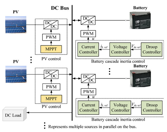
Figure 1.
Overall control structure of PV-battery DC microgrid.
2. Flexible V-P Droop Coefficient-Based Inertia Control
2.1. V-P Characteristic-Based Droop Control
The relationship between the DC voltage and the active power of each battery converter can be used in the DC voltage droop control to achieve the goal of sharing the DC voltage control among multiple batteries. The relationship between DC voltage and active power is as follows:
where Vdc is the battery converter output voltage; Vdc ref is the reference value of the battery converter output voltage generated by the droop controller; P is the battery converter output active power; Pref is the rated value of the battery converter output active power, with the power being positive in the direction of flow into the bus; and 1/G1 is expressed as the coefficient of the droop curve.
In Equation (1), when the battery adopts the V-P characteristic-based droop control, the battery converter output power P is expressed as:
2.2. Inertia Analysis of Battery Converter
The batteries connect to the DC bus in parallel through the current-reversible bidirectional half-bridge DC/DC converter. The circuit model of the battery bidirectional DC/DC converter and the power relationship on the capacitor side are shown in Figure 2.
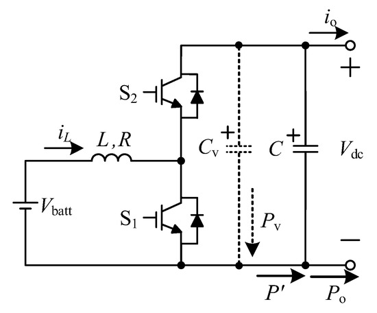
Figure 2.
The battery bidirectional DC/DC converter model and the power relationship on the capacitor side.
As shown in Figure 2, Vbatt and iL are, respectively, the terminal voltage and terminal current of the battery; L and R are, respectively, the filter inductance and internal resistance; C is the inherent filter capacitor; Cv is the virtual capacitor; Vo is the DC bus voltage; io is the battery converter output current; Si is the power switch, i = 1,2; P′ is the active power of the converter flowing into the capacitor C when the battery adopts flexible V-P droop coefficient-based inertia control; Po is the active power flowing from the capacitor C to the DC bus; and Pv is the inertia power introduced. The power relationship between the inherent capacitance and the virtual capacitance side can be obtained as follows:
Supposing that the load power mutation is ΔPo, the active power can be rebuilt as:
Substituting Equations (3) and (4) into Equation (5), we have:
From Equation (6), it can be seen that the inertia control is introduced by increasing the virtual capacitor Cv on the DC side, which improves the power regulation ability of the system and provides a certain degree of inertia compensation for the DC microgrid. Moreover, the control method improves the ability of the bus voltage to cope with sudden changes in the load power, which is conducive to the stable operation of the system.
2.3. Flexible V-P Droop Coefficient-Based Inertia Control
From Equation (1), it can be seen that the change in the active power of the DC microgrid system immediately causes a change in the reference value of the battery converter output voltage Vdc ref. Taking into account the combination of the DC microgrid inertia and the voltage droop control, the adaptive adjustment of the DC microgrid inertia was investigated. When the active power of the DC microgrid changes, the parameters of the droop curve can be adjusted by correlating the voltage variation rate dVdc/dt to compensate the original droop curve and provide a certain degree of inertia for the microgrid, thus helping it cope with disturbances from external uncertain factors.
By improving the droop coefficient in Equation (1), a new droop expression for the battery converter can be obtained as follows:
The improved flexible droop coefficient with dVdc/dt is obtained as follows:
where G1 is the droop coefficient when the microgrid is in a steady state, and G2 is a dynamic coefficient.
Substituting Equation (8) into Equation (7), when the battery adopts flexible V-P droop coefficient-based inertia control, the battery converter output power P′ can be obtained as follows:
Combining Equations (2) and (9), P′ can be simplified as:
By virtue of Equation (3), it can be further obtained as:
Integrating over time on both sides of Equation (11) gives:
where W is the electric energy provided by the battery converter to the capacitor C side, and Wo is the electric energy provided by the capacitor C to the DC bus.
When the microgrid is in a steady state, it can be considered that Vdc ref ≈ Vdc, and Equation (12) can be adapted as follows:
According to Equation (13), the virtual inertia control variable droop coefficient can be utilized to increase the DC-side capacitance of the converter at the instant when the system is perturbed; i.e., the virtual capacitance. The value of the virtual capacitor Cv can be adjusted by changing the value of G2 as follows, so that the inertia of the system can be changed.
To prevent the droop coefficient from exceeding the limit, the upper limit Gmax and the lower limit Gmin of the variation range of the dynamic droop coefficient G2 need to be set. The hyperbolic tangent function tanh (·) is employed to restrict the dynamic droop coefficient:
The new dynamic variable droop coefficient is expressed as follows:
The curve of the new dynamic flexible droop coefficient is shown in Figure 3. If the absolute value of dVdc/dt is small, the droop coefficient curve approximates a straight line with a fixed slope G2. If the absolute value of dVdc/dt is large, the droop coefficient will not exceed the limit due to the limit of the hyperbolic tangent function tanh (·). The battery can provide appropriate inertia for the DC microgrid regardless of whether the load fluctuation is large or small.
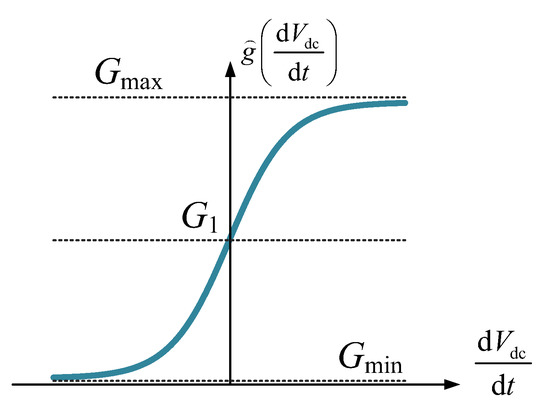
Figure 3.
Flexible curve of the droop coefficient.
3. NTSMC for Tracking Voltage and Current References
3.1. Model of the Battery Bidirectional DC–DC Converter
As indicated by the battery bidirectional DC/DC converter model shown in Figure 2, S1 is controlled by a drive signal with a duty cycle of u, and S2 is controlled by the complementary PWM signal of S1. Depending on Kirchhoff’s voltage–current law, the state space model of the battery converter circuit is expressed as:
In the bidirectional DC-DC converter, when 1 − u = Vbatt/Vdc, there is no power exchange between the battery and DC bus; when 1 − u < Vbatt/Vdc, the battery is in a discharging state; when 1 − u > Vbatt/Vdc, the battery is in a charging state. Thus, the bidirectional flow of battery power can be realized by regulating u.
Assuming that the nominal values of L, R, and C are, respectively, L0, R0, and C0, the corresponding deviations are defined as ΔL = L − L0, ΔR = R − R0, and ΔC = C − C0.
3.2. NTSMC for Tracking Voltage and Current References
To improve the ability of the DC microgrid to suppress model uncertainty, parameter perturbation, and external disturbance; solve the singular problem in ordinary TSMC; improve the dynamic process of error convergence; and increase the convergence speed, exponential reaching law-based NTSMC was used to design the voltage-loop and current-loop control laws.
The deviations zV and zi of the actual and reference values of the voltage loop and current loop can be defined as:
where iL ref is the output current reference value of the voltage controller.
Referring to NTSMC theory [22], the NTSMC switching functions for the voltage loop and the current loop were designed as follows:
where βV > 0, βi > 0; pV, qV, pi, and qi are positive odd numbers; 1 < pV/qV < 2; and 1 < pi/qi < 2.
Combining Equation (21) and Equation (22), the derivatives of sV and si can be expressed as:
After defining , , and λV > 0 and λi > 0, the derivatives of sV and si can be re-expressed as:
It is hard to predict the arrival phase for the sliding mode control because the preliminary condition of the system is not on the sliding mode surface. To ensure that the switching functions sV and si of the voltage loop and current loop can converge within a finite time, the exponential reaching laws of sV and si were designed as:
where ηV > 0, ηi > 0, εV > 0, and εi > 0.
Combining Equation (17), Equation (19), Equation (25), and Equation (27), the control law for the voltage loop is expressed as:
where the parameter Φ is expressed as:
Since the response speed of the second-level voltage loop is much faster than the first-level droop control loop, it can be considered that dVdc ref/dt = 0. Ignoring the uncertain terms uiL and ΦΔC, the control law iL ref of the voltage loop is re-expressed as:
Combining Equations (18), (20), (26) and (28), the control law of the current loop is expressed as:
where the parameter Ψ is expressed as:
In the same way, since the responsiveness of the third-level current loop is far swifter than the second-level voltage loop, it can be considered that diL ref/dt = 0. Ignoring the uncertain terms ΔL and ΔR in the system, the control law u of the current loop is re-expressed as:
The Lyapunov functions VV and Vi of the voltage-loop and current-loop control laws can be defined as:
Combining Equations (17), (19), (25), (27) and (31), the derivative of VV can be expressed as:
If , can be set to obtain the value range of ηV:
Combining Equations (18), (20), (26), (28) and (34), the derivative of Vi can be expressed as:
If , can be set to obtain the value range of ηi as follows:
It can be seen from Equations (38) and (40) that and can be obtained by adjusting the values of ηV, ηi, λV, and λi and the Lyapunov stability conditions of the designed voltage-loop and current-loop control laws ensured.
The cascade control flowchart associated with the flexible V-P droop coefficient-based inertia control and NTSMC for tracking voltage and current references is shown in Figure 4.
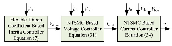
Figure 4.
Cascade control flowchart.
3.3. NTSMC Performance Analysis for Tracking Voltage and Current References
In order to further demonstrate the advantages of NTSMC controllers, we used NTSMC and PI, respectively, to compare the tracking performance with regard to voltage and current references. The overshoot and response time of the output voltage Vdc were compared in detail when the reference voltage changed. The Performance analysis and comparison of NTSMC and PI are shown in Table 1.

Table 1.
Performance analysis and comparison of NTSMC and PI.
At the initial moment of simulation, we set the output voltage reference value Vdc ref to 200 V. When the time = 1 s and 3 s, Vdc ref jumped to 400 V and 300 V, respectively, as shown in Figure 5.
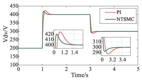
Figure 5.
NTSMC and PI response performance comparison.
4. Simulation Results
The multi-case simulation of the cascade control for an isolated PV-battery DC microgrid described in this paper was carried out in MATLAB/Simulink. The parameters of the proposed NTSMC are shown in Table 2.
Table 2.
Parameters of the proposed NTSMC for tracking voltage and current references.
4.1. Scheme I: Condition Involving Sudden Changes in Load Power
In the isolated PV-battery DC microgrid, the PV uses MPPT control and the battery uses the proposed cascade control (CC). The PV and the battery share the DC microgrid electricity demand according to their respective power ratios. The output power of the PV remains at 3000 W. At the initial moment, the load power is 2000 W; the load power abruptly increases to 3000 W when time = 2 s; the load power abruptly increases to 5000 W when time = 4 s. Figure 6 shows the simulation under the condition involving sudden changes in load power comparing the proposed CC method to the traditional droop control and PI control method (TDPI). Pload is the load power; PPV is the output power of the PV; Pbatt is the output power of the battery; SoC is the state of charge of the battery; and is the flexible droop coefficient.
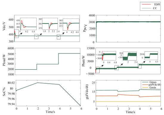
Figure 6.
Simulation under the condition involving sudden changes in load power.
From Figure 6, it can be seen that, when the load power suddenly changes, the droop coefficient of the battery converter changes rapidly, which leads to the rapid adjustment of the discharge power of the battery to maintain the stability of the bus voltage. Compared to the TDPI control method, the proposed CC method can accelerate the response time of the battery converter output voltage and reduce the overshoot significantly when the load power suddenly changes. It can be seen from the SoC curves that the additional power required for inertia control is small and not always needed, so the SoC curves are basically parallel when the battery adopts the CC and TDPI methods.
4.2. Scheme II: Condition Involving Out-of-Operation PV Failure
This simulation scheme analyzes the impact of out-of-operation PV failure on the system. From time = 0 s to 2 s, the PV output power remains at 3000 W, and the load power remains at 2000 W. When time = 2 s, the PV suddenly fails to run due to being out of operation, and the PV output power is zero. The simulation results are shown in Figure 7. The battery uses the CC method for the isolated PV-battery DC microgrid, and it is compared with the TDPI method.
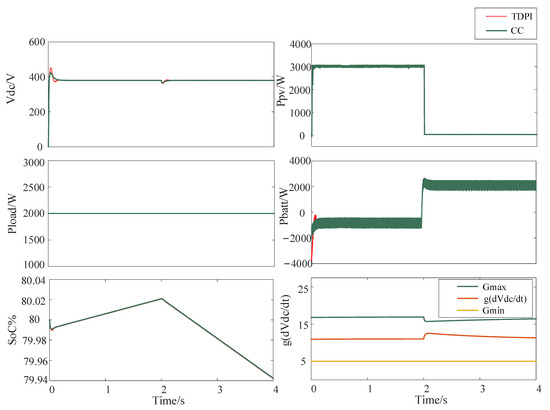
Figure 7.
Simulation under the condition involving out-of-operation PV failure.
As can be seen from Figure 7, when the PV suddenly fails to run due to being out of operation, the battery adopting the proposed CC method more quickly adjusts the state of charge and discharge to provide the power required by the load compared to the TDPI method. The robustness of the bus voltage is enhanced, and good voltage regulation is obtained for the independent DC microgrid.
4.3. Scheme III: Condition Involving Continuous Load Fluctuation
To verify the effect of the CC method proposed in this paper on the continuous dynamic change, the system was simulated under the condition involving a continuous load fluctuation. The output power of the PV remains at 3000 W. From time = 0 s to 2 s, the load power fluctuates randomly within the range of 2000~3000 W; from time = 2 s to 4 s, the load power fluctuates randomly within the range of 3000~4000 W; from time = 4 s to 6 s, the load power fluctuates randomly within the range of 2500~3500 W. Figure 8 shows the simulation results under the condition involving continuous load fluctuation.
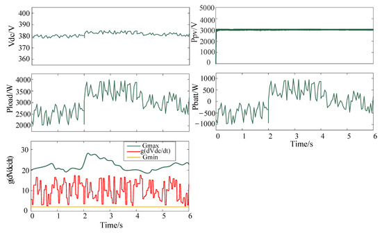
Figure 8.
Simulation under the condition involving continuous load fluctuation.
From Figure 8, it can be seen that the battery converter output voltage certainly fluctuates with the continuous change in the load power. Since the droop coefficient of the battery converter changes rapidly, the inertia of the system increases, the fluctuation range of the battery converter output voltage is small, and the system can run stably. It can be seen from the power curve that, when the load power fluctuates continuously, the battery accepts most of the randomly fluctuating power of the load through rapid power adjustment, which plays a role in smoothing the power.
5. Experimental Results
The hardware for the experiment platform is shown in Figure 9. In the experiment, the voltage source series resistance was equivalent to the photovoltaic cell, and the sudden change in illumination was simulated by switching the series resistance. A TMS320F28335 processor (TI Company) was adopted as the main control chip for the bidirectional DC/DC converter. The current measuring circuit of the converter used 10 mω copper wire as the sampling resistance. SiC-N-channel MOSFET was selected as the switch tube for the bidirectional DC/DC converter, adopting the unipolar PWM trigger mode. The PWM driving circuit of the bidirectional DC/DC converter adopted an IR2104 power driving chip and a 6N137 optocoupler chip.
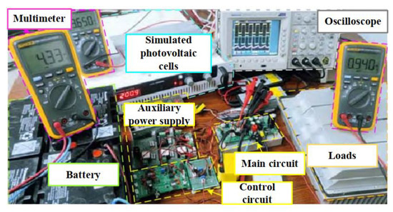
Figure 9.
Hardware for the experiment platform.
Figure 10 shows a comparison of the results for the battery converter output voltage Vdc and battery terminal current iL with the proposed CC and TDPI methods. In Figure 10a, Vdc ref is set as 250 V and the load power Pload decreases from 2 kW to 1 kW. In Figure 10b, Vdc ref is set as 250 V and the load power Pload suddenly increases from 1 kW to 2 kW.
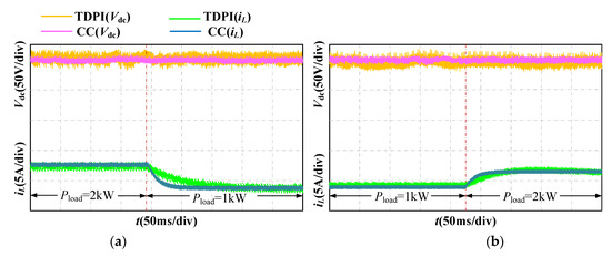
Figure 10.
Experimental results for sudden load power change. (a) Load power suddenly decreases to 1 kW; (b) load power suddenly increases to 2 kW.
It can be seen that, compared with the TDPI method, the DC bus voltage with the proposed CC method has a smaller fluctuation range, which is caused by the load power mutation, and the battery converter can adjust the charging and discharging power more quickly. In other words, the proposed CC method can not only effectively suppress the DC bus voltage fluctuation and improve the stability of the bidirectional DC/DC converter but also produce a fast dynamic response when the system load changes.
Figure 11a,b show the comparison of the results for the battery converter output voltage Vdc with the proposed CC and TDPI methods when the reference value of the battery converter output voltage Vdc ref suddenly increases from 200 V to 225 V and decreases from 250 V to 210 V, respectively.
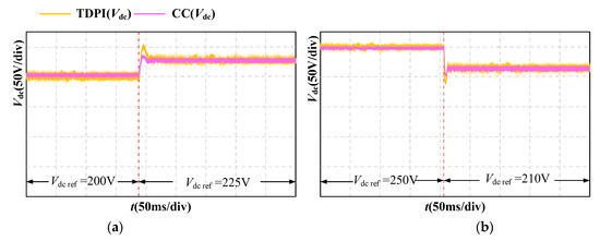
Figure 11.
Experimental results for sudden change in reference voltage. (a) Vdc ref suddenly increases to 225 V; (b) Vdc ref suddenly decreases to 210 V.
Obviously, the proposed CC method shows lower overshoot, faster response speed, and shorter stability time than the TDPI when tracking voltage reference Vdc ref changes. This confirms that the proposed control strategy has better transient and steady-state performance when tracking the changes in the voltage reference value.
Figure 12 shows a comparison of the results when the PV fails due to being out of operation. It can be observed that the battery controlled with the proposed CC method adjusts the discharging state more quickly to provide the power required by the load. The robustness of the bus voltage is obviously enhanced, and good voltage regulation is obtained in the independent DC microgrid.
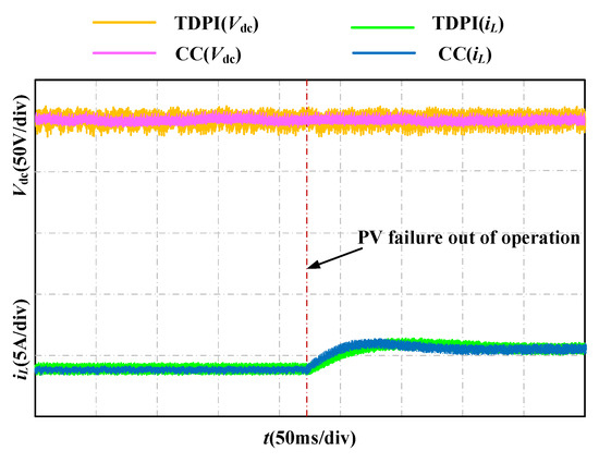
Figure 12.
Experimental results for out-of-operation PV failure.
6. Conclusions
A CC method for an isolated PV-battery DC microgrid was here proposed that makes each power unit share the power demand of the DC microgrid according to its own power ratio. The simulation experiments and analyses were performed under three conditions: sudden change in load power, out-of-operation PV failure, and continuous load fluctuation. The simulated and experimental results show that the flexible V-P droop coefficient-based inertia control proposed in this paper uses the rapidity of inertia control to provide inertia support for the battery converter output voltage, which significantly enhances the flexibility of the system and improves the poor quality of the bus voltage caused by power fluctuations. Compared to the TDPI method, the proposed CC method can quickly change the droop coefficient of the battery converter in response to sudden changes in load power, out-of-operation PV failures, and continuous load fluctuations. In addition, coordinated distribution of power and balancing of charge states between batteries in the multi-source microgrid can be achieved by flexibly adjusting the charge and discharge power of the batteries. The battery converter output voltage shows lower overshoot and shorter settling time and has good anti-disturbance performance.
Author Contributions
Conceptualization, Z.Y. and S.X.; methodology, Z.Y. and S.X.; software, Z.W. and F.Y.; validation, Z.Y. and Z.W.; formal analysis, Z.Y.; investigation, Z.Y.; resources, S.X.; data curation, F.Y. and H.C.; writing—original draft preparation, Z.W.; writing—review and editing, Z.Y.; visualization, F.Y.; supervision, F.Y.; project administration, S.X. All authors have read and agreed to the published version of the manuscript.
Funding
This research was funded by the Intelligent Operation and Maintenance Technology of Distributed Photovoltaic System Program of the National Key Research and Development Plan, grant number 2018YFB1500804.
Conflicts of Interest
The authors declare no conflict of interest.
Nomenclature
| Vdc | Battery converter output voltage | u | Drive signal with a duty cycle |
| Vdc ref | Reference value of the battery converter output voltage | L0 | Nominal values of L |
| P | Battery converter output active power | R0 | Nominal values of R |
| Pref | Rated value of the battery converter output active power | C0 | Nominal values of C |
| Vbatt | Terminal voltage of the battery | zV | Deviations of actual and reference values of the voltage loop |
| io | Battery converter output current | zi | Deviations of actual and reference values of the current loop |
| iL | Terminal current of the battery | iLref | Output current reference value of the voltage controller |
| L | Filter inductance | sV | NTSMC switching functions of the voltage loop |
| R | Internal resistance | si | NTSMC switching functions of the current loop |
| C | Inherent filter capacitor | VV | Lyapunov functions of the voltage-loop control laws |
| Cv | Virtual capacitor | Vi | Lyapunov functions of the current-loop control laws |
| Wo | Electric energy provided by the capacitor C to the DC bus | Vo | DC bus voltage |
| G1 | Droop coefficient when the microgrid is in a steady state | Si | Power switch |
| G2 | Dynamic coefficient | P′ | Active power of the converter flowing to the capacitor C when the battery adopts flexible V-P droop coefficient-based inertia control |
| Gmax | Upper limit of the dynamic coefficient | Po | Active power flowing from the capacitor C to the DC bus |
| Gmin | Lower limit of the dynamic coefficient | Pv | Introduced inertia power |
| dVdc/dt | Voltage variation rate | W | Electric energy provided by the battery converter to the capacitor C side |
| Abbreviation | |||
| TSMC | Terminal sliding mode control | TDPI | Traditional droop control and PI control method |
| NTSMC | Nonsingular terminal sliding mode control | CC | The cascade control proposed in this paper |
References
- Okwako, O.E.; Lin, Z.-H.; Xin, M.; Premkumar, K.; Rodgers, A.J. Neural Network Controlled Solar PV Battery Powered Unified Power Quality Conditioner for Grid Connected Operation. Energies 2022, 15, 6825. [Google Scholar] [CrossRef]
- Pranith, S.; Kumar, S.; Singh, B.; Bhatti, T.S. Improved Gaussian Filter Based Solar PV-BES Microgrid With PLL Based Islanding Detection and Seamless Transfer Control. IEEE Trans. Ind. Electron. 2022, 69, 5815–5825. [Google Scholar] [CrossRef]
- Alramlawi, M.; Li, P. Design Optimization of a Residential PV-Battery Microgrid with a Detailed Battery Lifetime Estimation Model. IEEE Trans. Ind. Appl. 2020, 56, 2020–2030. [Google Scholar] [CrossRef]
- Valibeygi, A.; Konakalla, S.A.R.; Callafon, R.D. Predictive Hierarchical Control of Power Flow in Large-Scale PV Microgrids With Energy Storage. IEEE Trans. Sustain. Energy 2021, 12, 412–419. [Google Scholar] [CrossRef]
- Shubhra, S.; Singh, B. Three-Phase Grid-Interactive Solar PV-Battery Microgrid Control Based on Normalized Gradient Adaptive Regularization Factor Neural Filter. IEEE Trans. Ind. Inform. 2020, 16, 2301–2314. [Google Scholar] [CrossRef]
- Li, D.; Ho, C.N.M. Decentralized PV–BES Coordination Control with Improved Dynamic Performance for Islanded Plug-n-Play DC Microgrid. IEEE Trans. J. Emerg. Sel. Topics Power Electron. 2021, 9, 4992–5001. [Google Scholar] [CrossRef]
- Oliver, J.S.; David, P.W.; Balachandran, P.K.; Mihet-Popa, L. Analysis of Grid-Interactive PV-Fed BLDC Pump Using Optimized MPPT in DC–DC Converters. Sustainability 2022, 14, 7205. [Google Scholar] [CrossRef]
- Dragičević, T.; Guerrero, J.M.; Vasquez, J.C.; Škrlec, D. Supervisory Control of an Adaptive-Droop Regulated DC Microgrid With Battery Management Capability. IEEE Trans. Power Electron. 2014, 29, 695–706. [Google Scholar] [CrossRef]
- Beerten, J.; Belmans, R. Analysis of Power Sharing and Voltage Deviations in Droop-Controlled DC Grids. IEEE Trans. Power Syst. 2013, 28, 4588–4597. [Google Scholar] [CrossRef]
- Shi, M.; Chen, X.; Zhou, J.; Chen, Y.; Wen, J.; He, H. Advanced Secondary Voltage Recovery Control for Multiple HESSs in a Droop-Controlled DC Microgrid. IEEE Trans. Smart Grid. 2019, 10, 3828–3839. [Google Scholar] [CrossRef]
- Wang, W.; Li, Y.; Cao, Y.; Häger, U.; Rehtanz, C. Adaptive Droop Control of VSC-MTDC System for Frequency Support and Power Sharing. IEEE Trans. Power Syst. 2018, 33, 1264–1274. [Google Scholar] [CrossRef]
- Zhang, S.; Zhou, M.; Li, G. Applying power margin tracking droop control to flexible operation in multi-terminal DC collector systems of renewable generation. CSEE J. Power Energy Syst. 2021, 7, 1176–1186. [Google Scholar]
- Prabhakaran, P.; Goyal, Y.; Agarwal, V. Novel nonlinear droop control techniques to overcome the load sharing and voltage regulation issues in DC microgrid. IEEE Trans. Power Electron. 2018, 33, 4477–4487. [Google Scholar] [CrossRef]
- Lu, X.; Guerrero, J.M.; Sun, K.; Vasquez, J.C. An improved droop control method for DC microgrids based on low bandwidth communication with DC bus voltage restoration and enhanced current sharing accuracy. IEEE Trans. Power Electron. 2014, 29, 1800–1811. [Google Scholar] [CrossRef]
- Vu, T.V.; Perkins, D.; Diaz, F.; Gonsoulin, D.; Edrington, C.S.; El-Mezyani, T. Robust adaptive droop control for DC microgrids. Electr. Power Syst. Res. 2017, 146, 95–106. [Google Scholar] [CrossRef]
- Ratnam, K.S.; Palanisamy, K.; Yang, G. Future low-inertia power systems: Requirements, issues, and solutions—A review. Renew. Sust. Energy Rev. 2020, 124, 109773. [Google Scholar] [CrossRef]
- Saxena, P.; Singh, N.; Pandey, A.K. Enhancing the dynamic performance of microgrid using derivative controlled solar and energy storage based virtual inertia system. J. Energy Storage 2020, 31, 101613. [Google Scholar] [CrossRef]
- Jami, M.; Shafiee, Q.; Gholami, M.; Bevrani, H. Control of a super-capacitor energy storage system to mimic inertia and transient response improvement of a direct current micro-grid. J. Energy Storage 2020, 32, 101788. [Google Scholar] [CrossRef]
- Mi, Y.; Zhang, H.; Fu, Y.; Wang, C.; Loh, P.C.; Wang, P. Intelligent power sharing of DC isolated microgrid based on fuzzy sliding mode droop control. IEEE Trans. Smart Grid. 2019, 10, 2396–2406. [Google Scholar] [CrossRef]
- Mohammadzadeh, A.; Kayacan, E. A novel fractional-order type-2 fuzzy control method for online frequency regulation in ac microgrid. Eng. Appl. Artif. Intell. 2020, 90, 103483. [Google Scholar] [CrossRef]
- Cucuzzella, M.; Lazzari, R.; Trip, S.; Rosti, S.; Sandroni, C.; Ferrara, A. Sliding mode voltage control of boost converters in DC microgrids. Control. Eng. Pract. 2018, 73, 161–170. [Google Scholar] [CrossRef]
- Chen, S.Y.; Lin, F.J. Robust Nonsingular Terminal Sliding-Mode Control for Nonlinear Magnetic Bearing System. IEEE Trans. Control. Syst. Technol. 2011, 19, 636–643. [Google Scholar] [CrossRef]


Publisher’s Note: MDPI stays neutral with regard to jurisdictional claims in published maps and institutional affiliations. |
© 2022 by the authors. Licensee MDPI, Basel, Switzerland. This article is an open access article distributed under the terms and conditions of the Creative Commons Attribution (CC BY) license (https://creativecommons.org/licenses/by/4.0/).