
Single-Phase Fault Tolerant Multilevel Inverter Topologies—Comprehensive Review and Novel Comparative Factors

 , , , and
Abstract
:1. Introduction
- MLI provides a high-quality output voltage waveform with low harmonic content; hence, total harmonic distortion (THD) is reduced considerably.
- Due to lower harmonic content, the need for low-frequency bulky filter requirement reduces, thereby reducing electromagnetic interference (EMI). Moreover, it has good electromagnetic compatibility (EMC).
- MLI provides low voltage stress across switches. Hence, it enables users to generate high voltages by using low-rating semiconductor devices.
- MLI can operate with both low frequency and a fundamental frequency modulation scheme satisfactorily. Switching losses are reduced in a low-frequency modulation scheme. Hence the efficiency of the inverter increases.
- The reduction in overall inverter loss reduces the requirement for cooling arrangement.
- MLI can provide FT operation under single- or multiple-switch faults.
- Tolerance to single and/or multiple OC and SC faults.
- Uninterrupted power supply to the loads.
- Satisfactory system efficiency.
- Fewer switches and other components.
- Lesser cost.
- Classification of MLI FT solutions.
- Review of single-phase FT MLI topologies with their constructional features, merits, and limitations.
- Comparison of different single-phase FT MLI based on proposed novel factors.
- Simulation and experimental verification of existing five-level FT MLI topology.
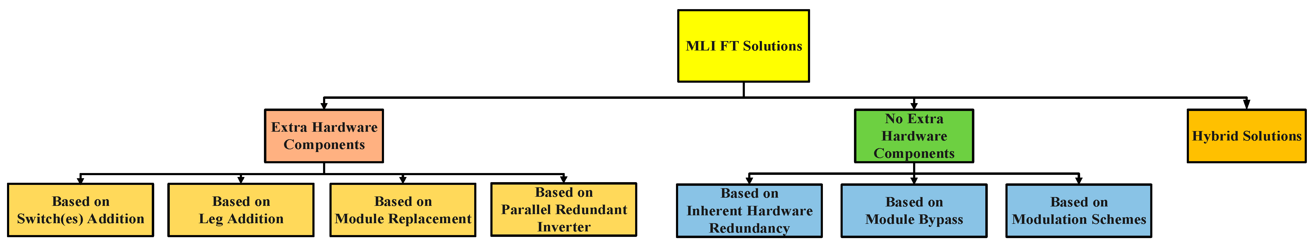
2. MLI FT Solutions
- Solution based on extra hardware components (EHC).
- Solution based on no extra hardware components (NEHC).
- Hybrid solutions.
2.1. MLI FT Solutions Based on EHC
- MLI FT solution based on switch(es) addition.
- MLI FT solution based on leg addition.
- MLI FT solution based on module replacement.
- MLI FT solution based on parallel redundant inverter.
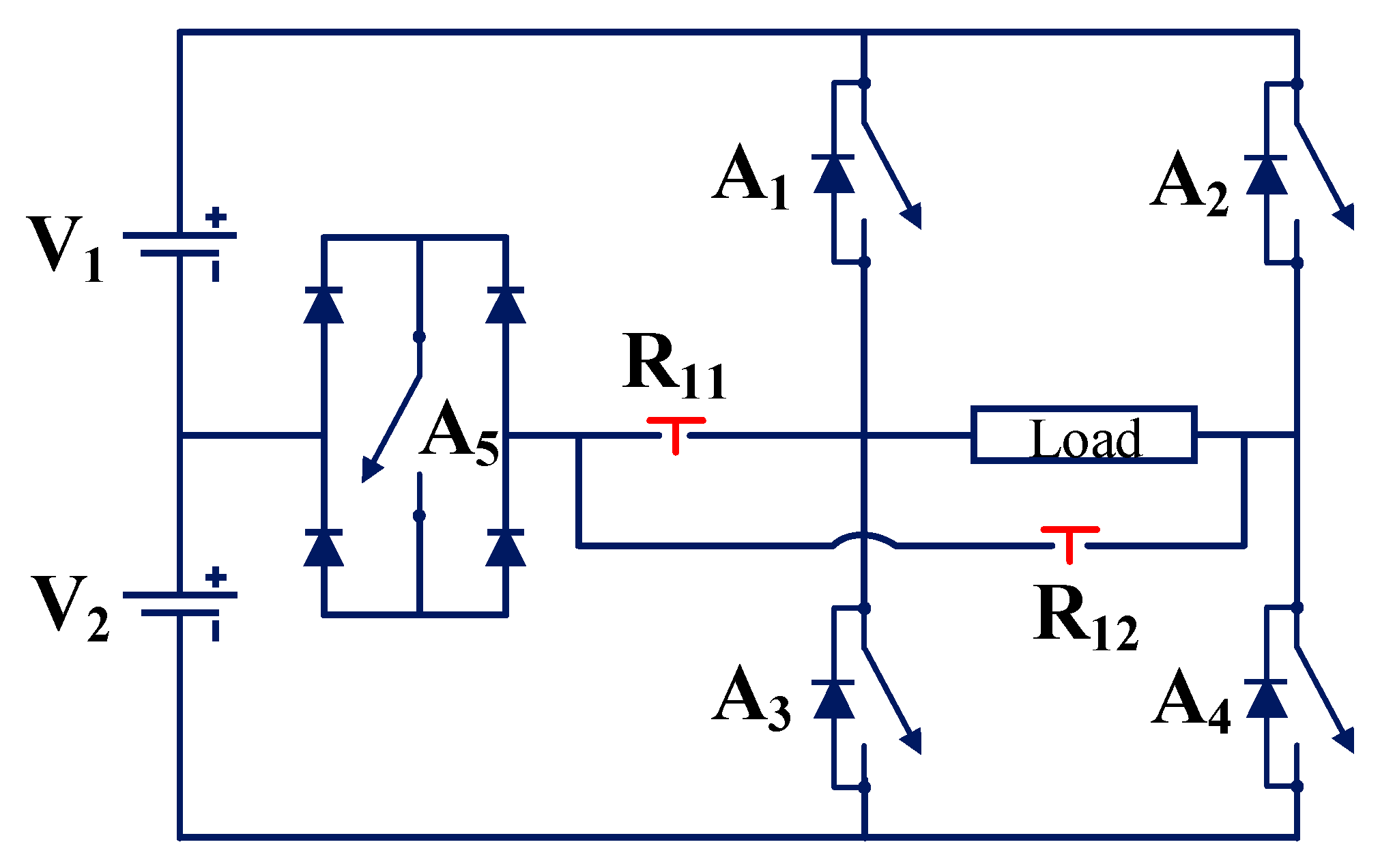
2.1.1. MLI FT Solution Based on Switch(es) Addition (SA)
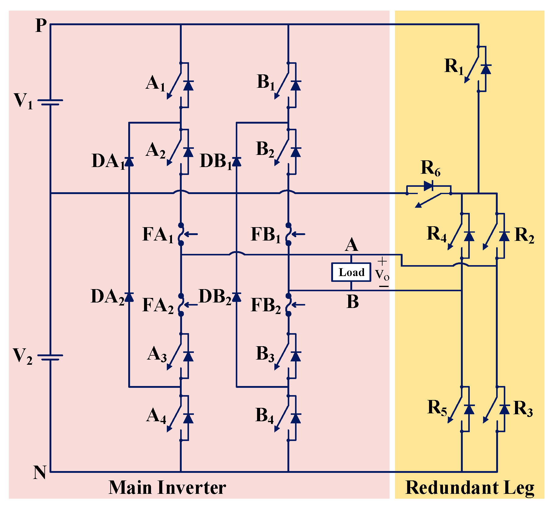
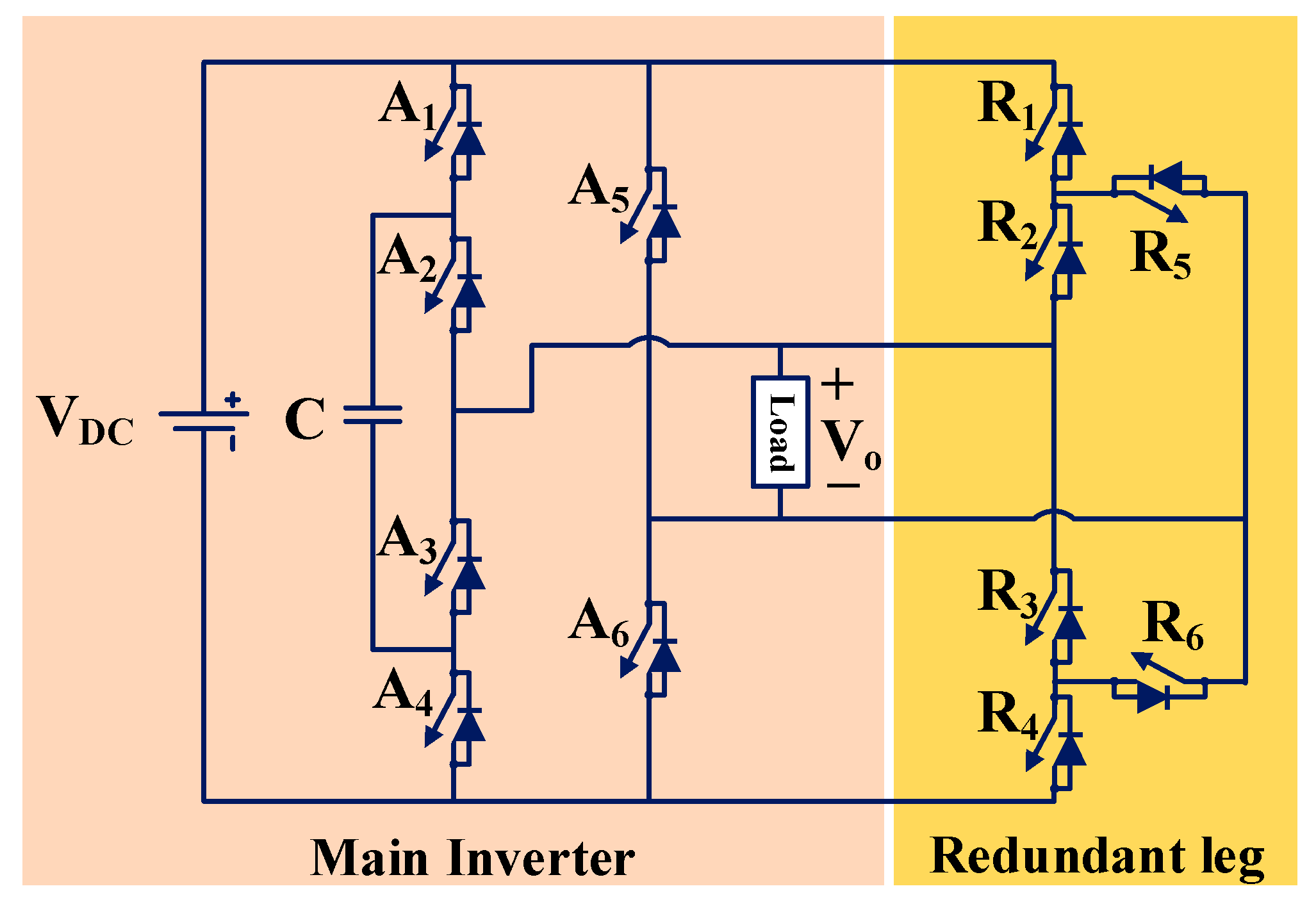
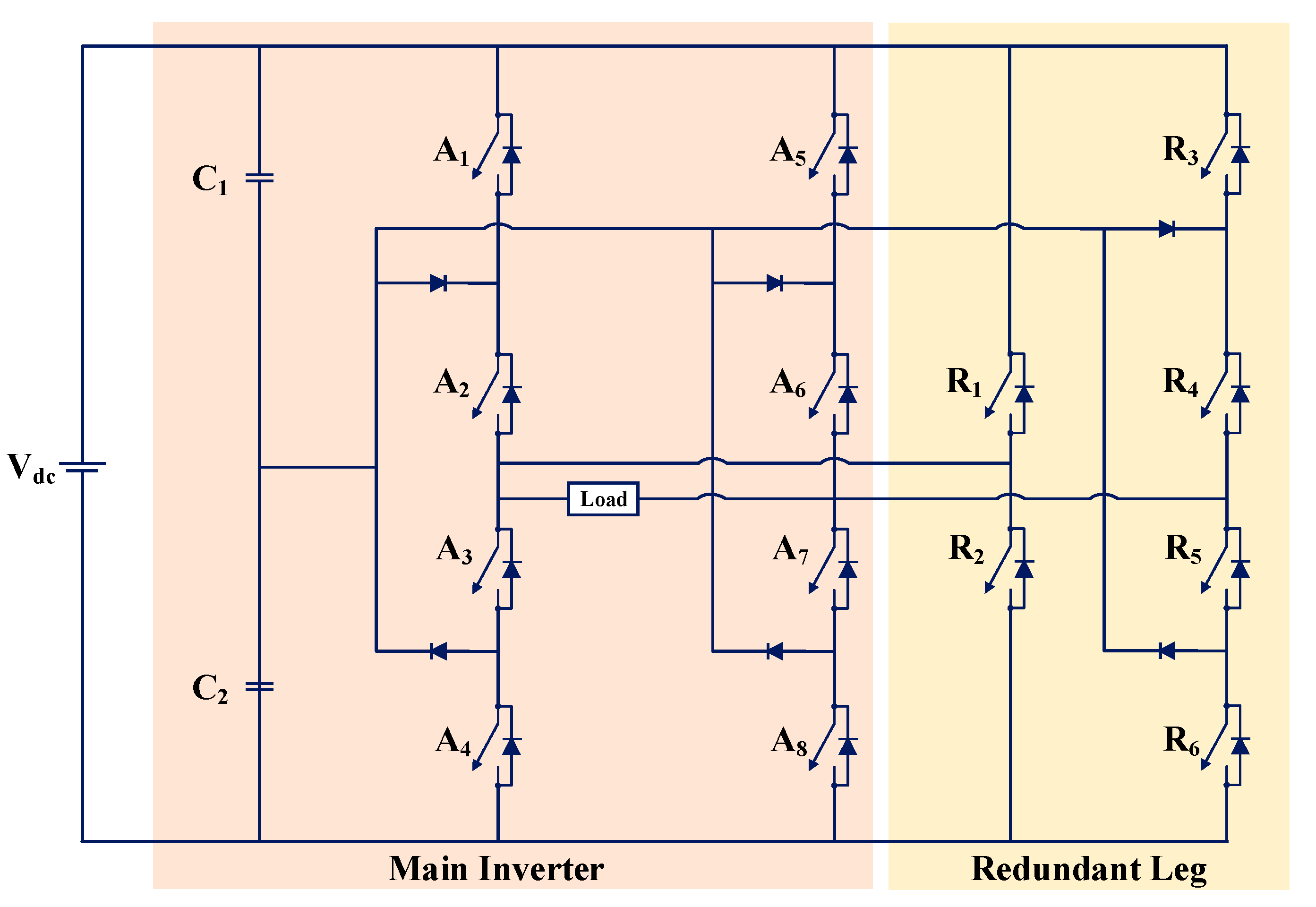
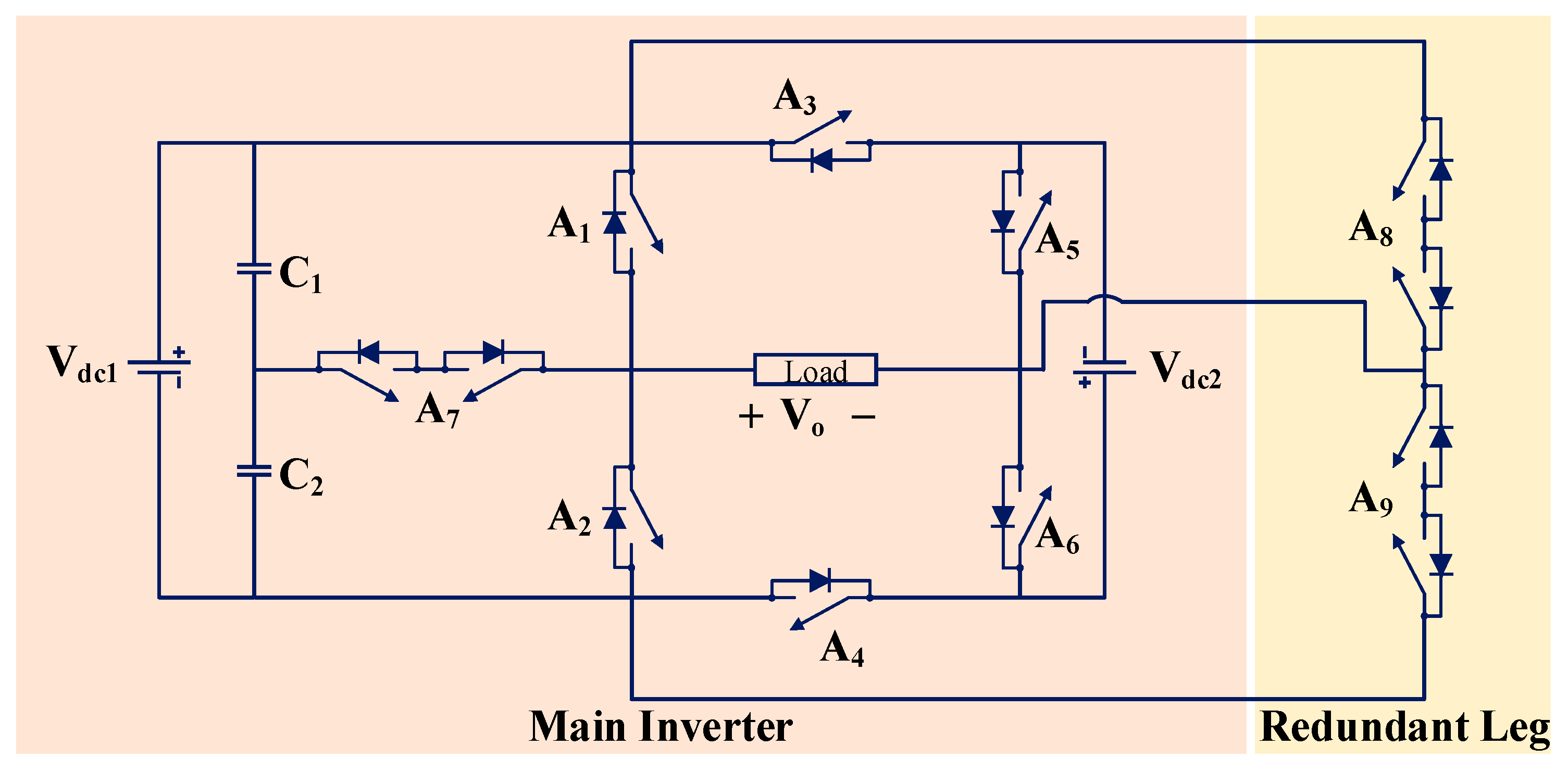
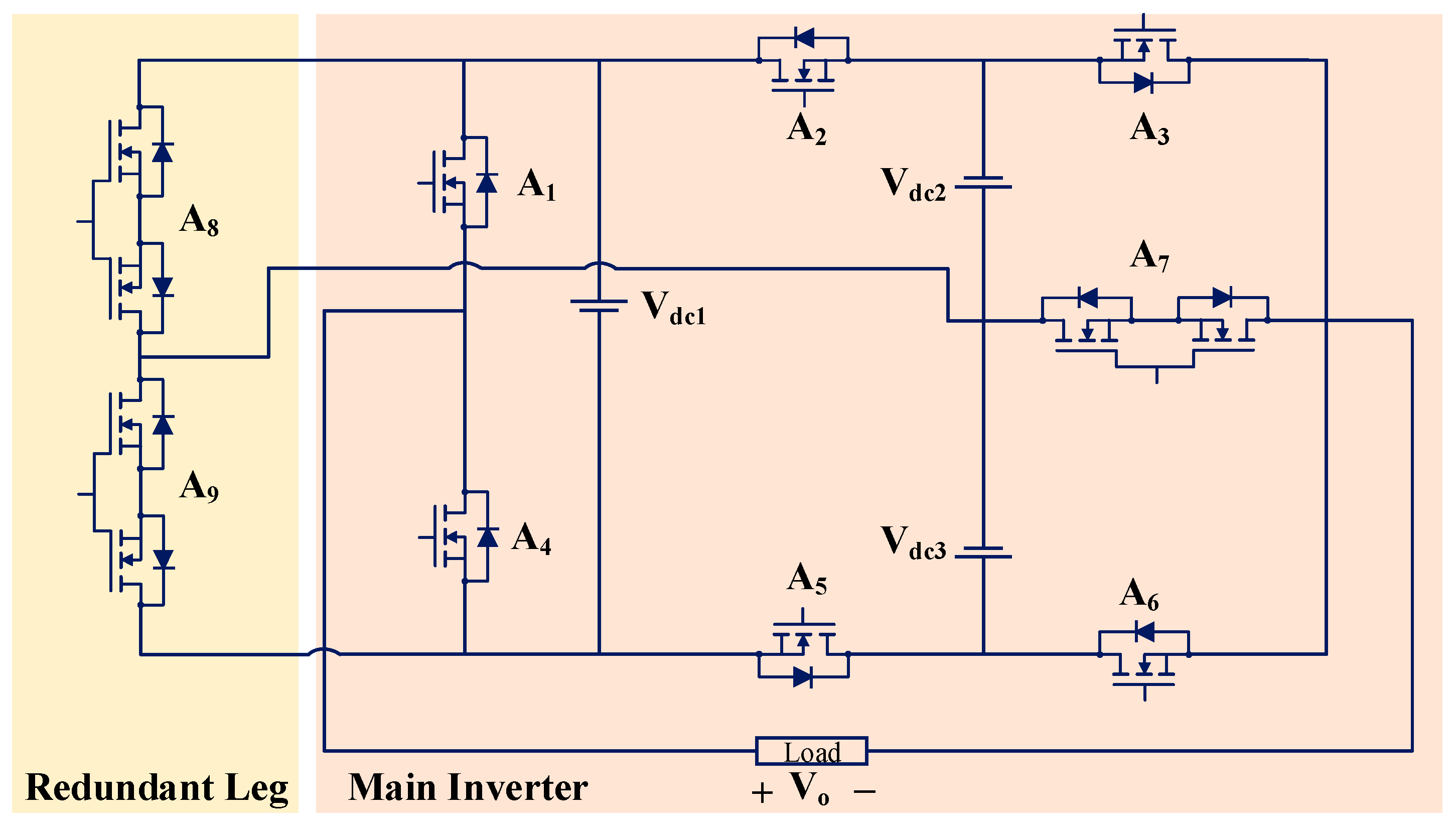
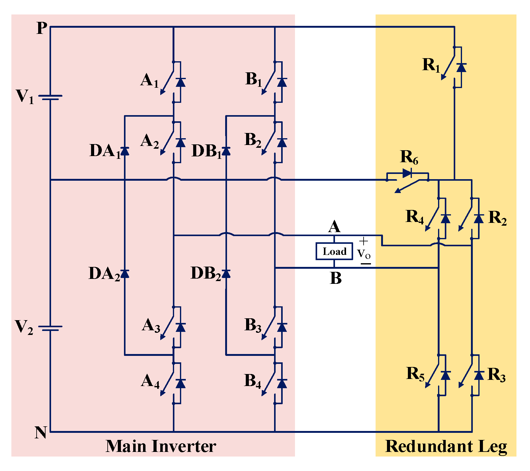
2.1.2. MLI FT Solution Based on Leg Addition (LA)
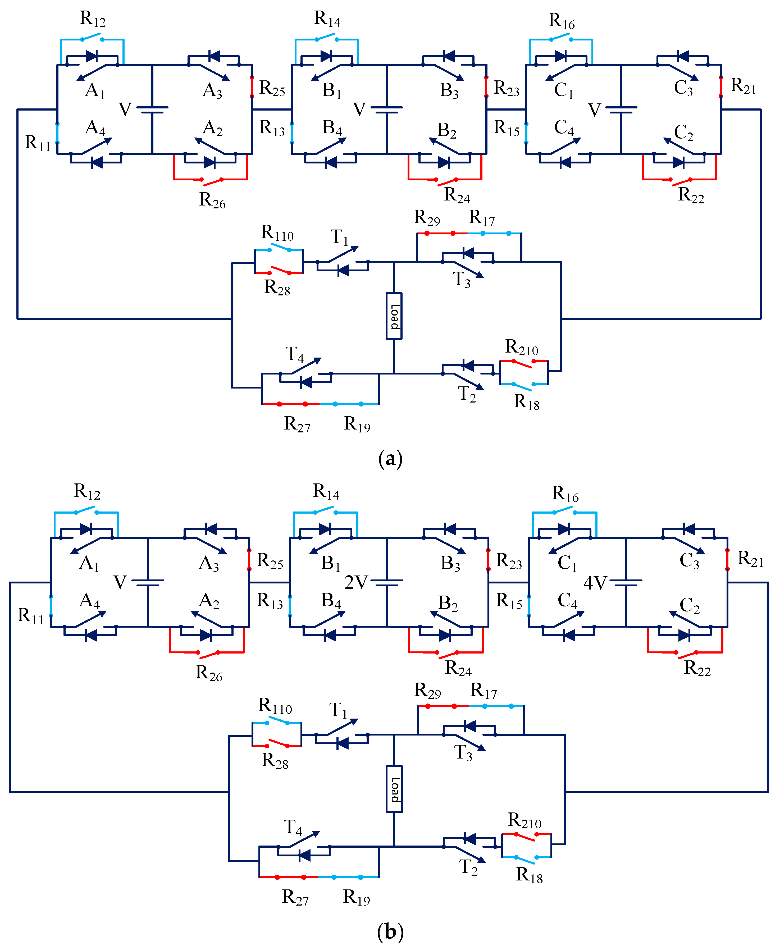
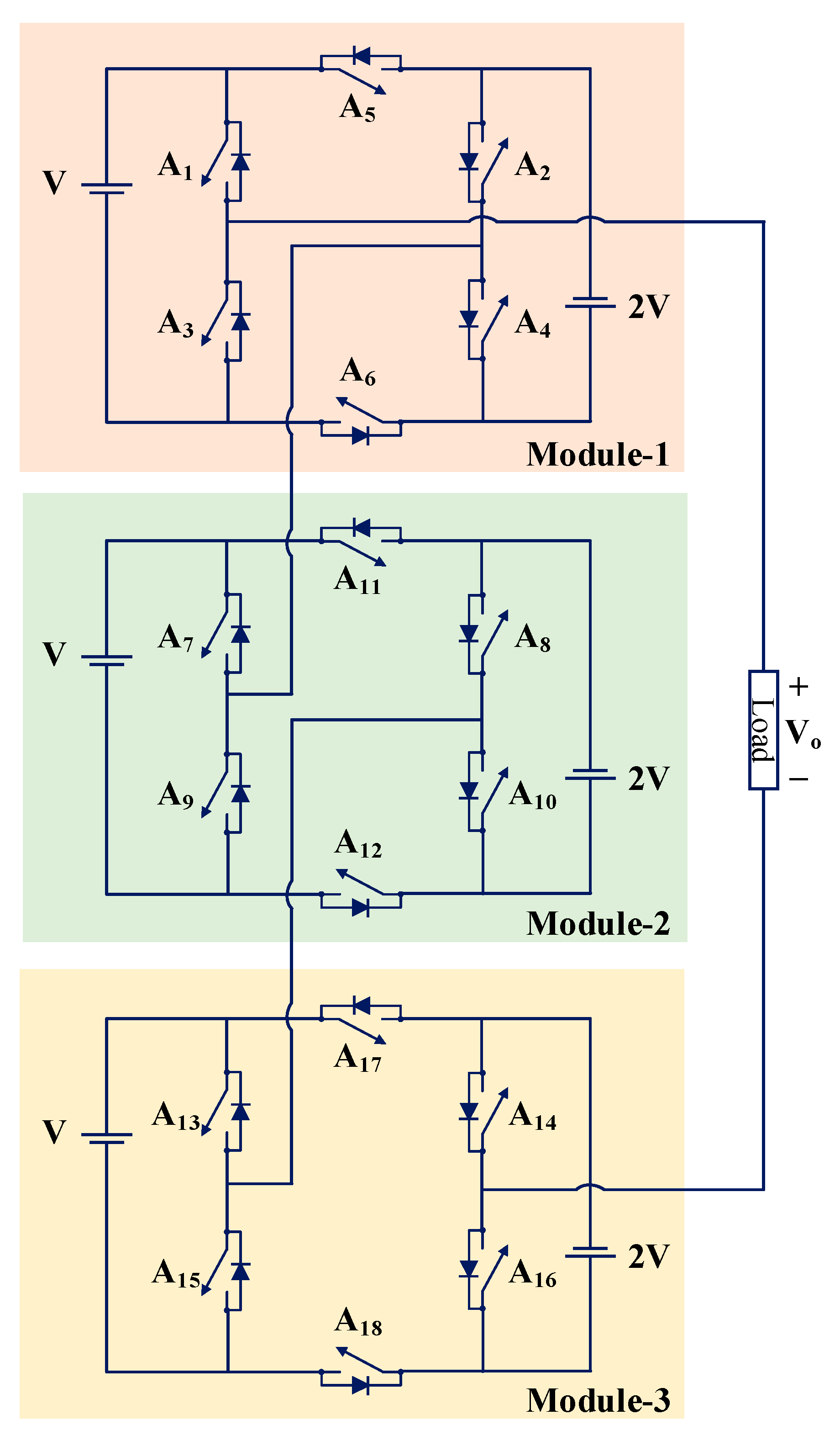
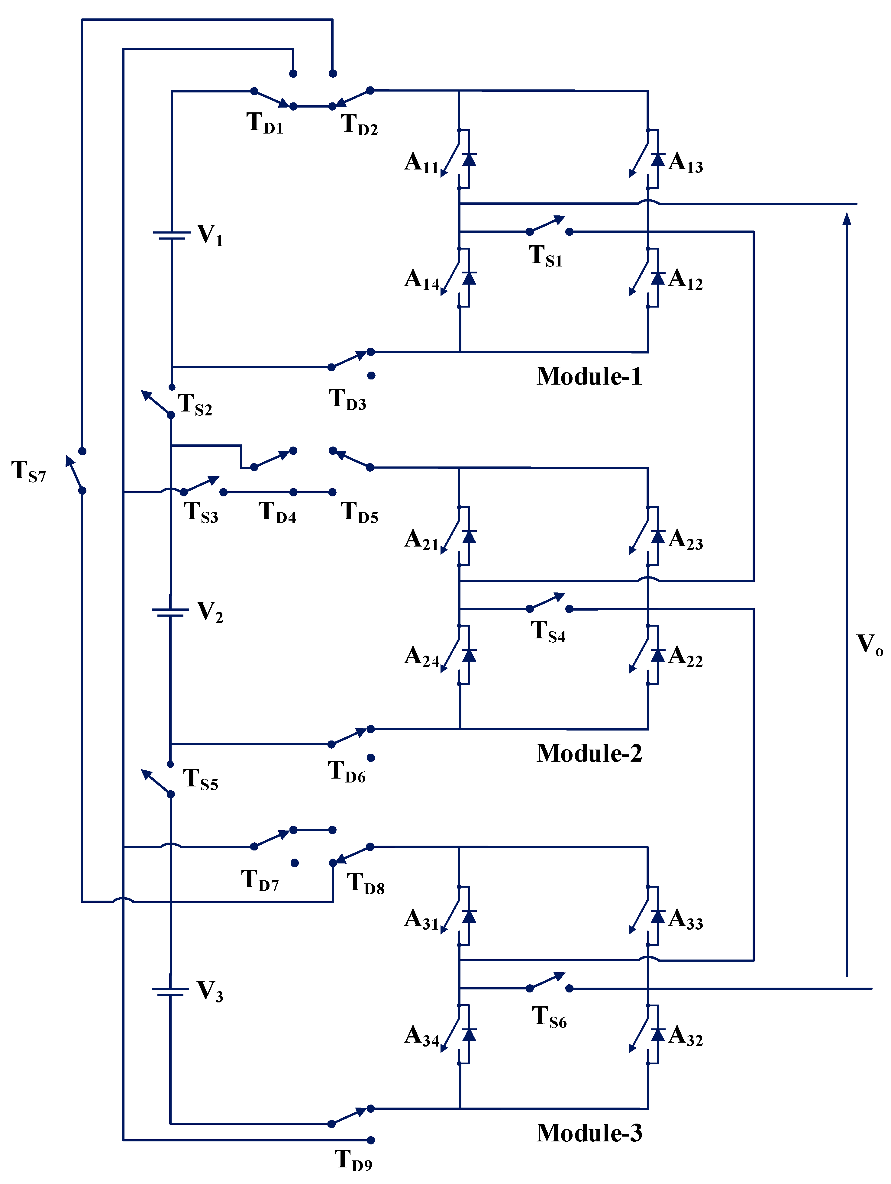
2.1.3. MLI FT Solution Based on Module Replacement (MR)
2.1.4. MLI FT Solution Based on Parallel Redundant Inverter (PRI)
2.2. MLI FT Solutions Based on NEHC
- MLI FT solution based on inherent hardware redundancy.
- MLI FT solution based on module bypass.
- MLI FT solution based on modulation scheme.
2.2.1. MLI FT Solution Based on Inherent Hardware Redundancy (IHR)
2.2.2. MLI FT Solution Based on Module Bypass (MB)
2.2.3. MLI FT Solution Based on Modulation Scheme (MS)
2.3. Hybrid Solutions
3. Review of Single-Phase FT MLI Topologies
3.1. Single-Phase FT MLIs
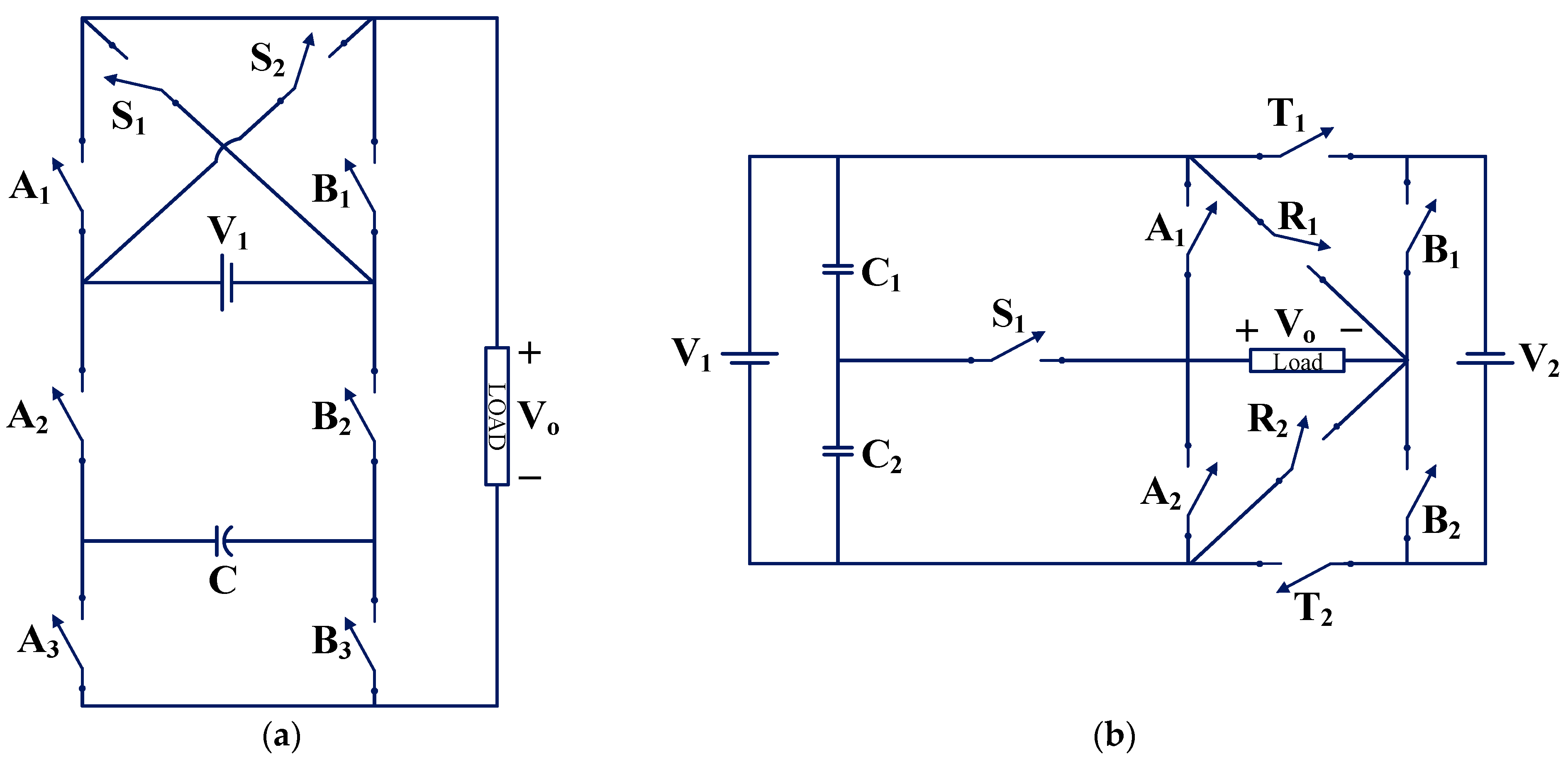
3.1.1. TP1 and TP2
3.1.2. TP3 and TP4
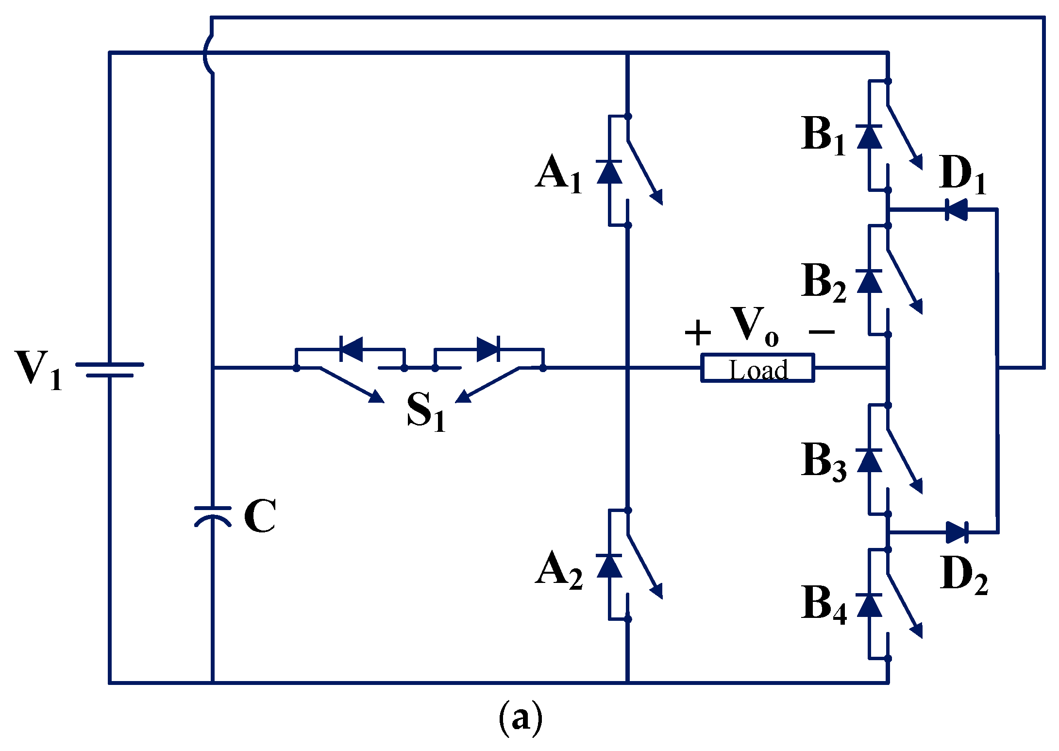
3.1.3. TP5
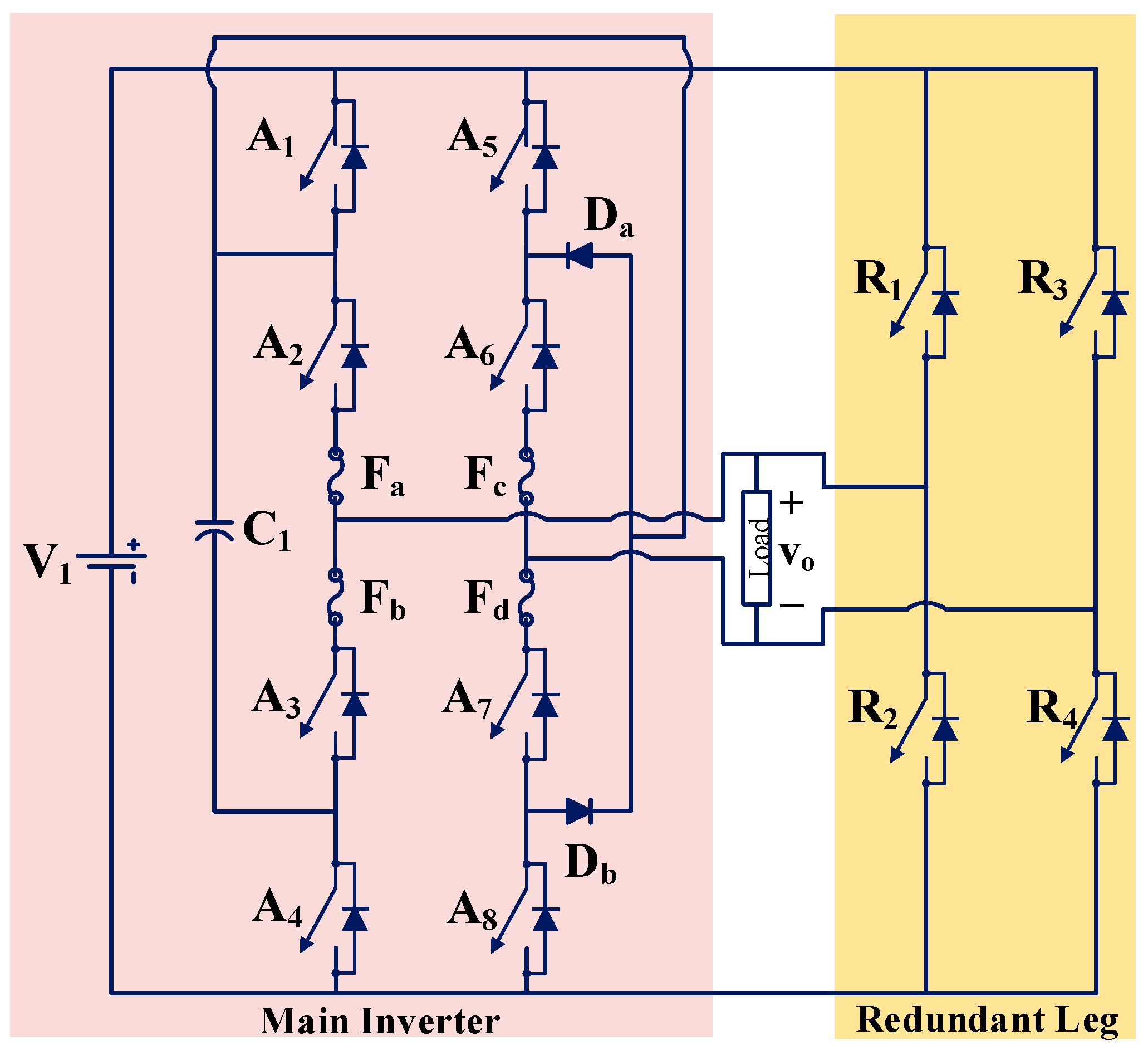
3.1.4. TP6
3.1.5. TP7
3.1.6. TP8 and TP9
3.1.7. TP10
3.1.8. TP11
3.1.9. TP12
- It has switching states which can bring two sources in parallel. Due to this advantage, it is possible to maintain power in post-fault similar to the pre-fault power.
- Single unit can be connected in series depending upon the number of output voltage levels required.
3.1.10. TP13
3.1.11. TP14
3.1.12. TP15 and TP16
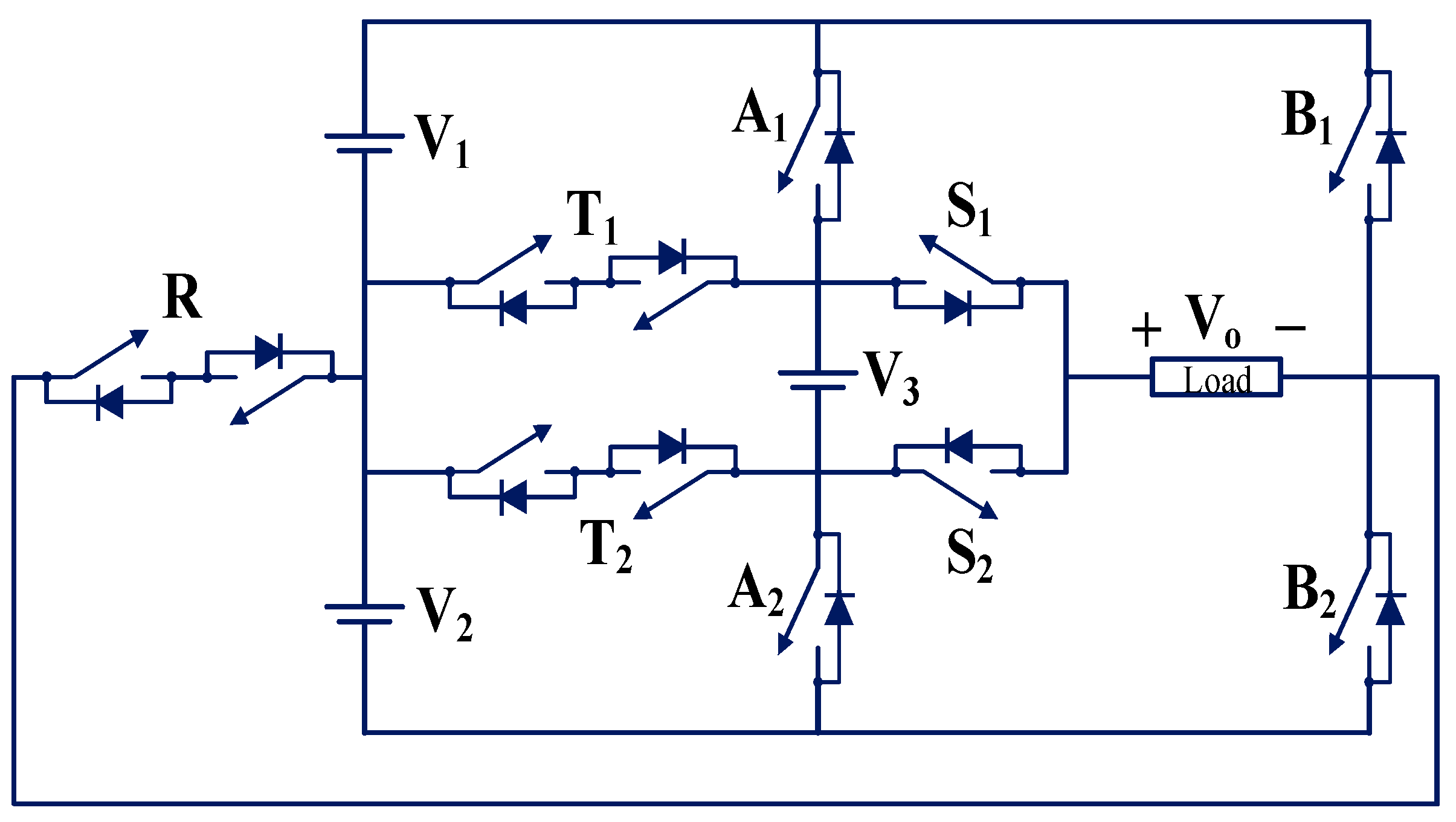
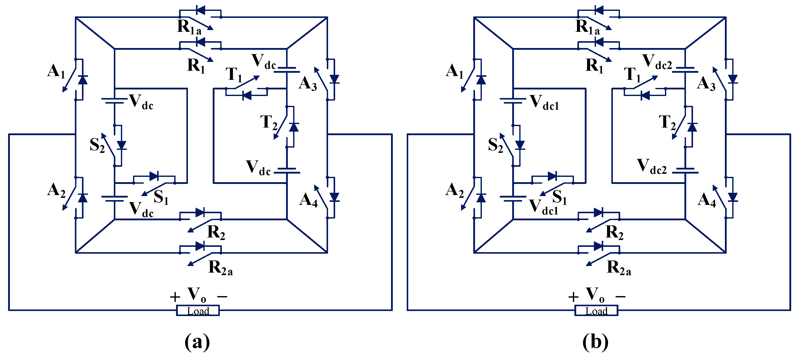
3.1.13. TP17
- TP17 topology is capable of tolerating faults caused by the failure of the source.
- TP17 reduces the uneven charging of batteries that is caused to partial shading or hotspots on one side of the PV panels due to energy-balancing between sources.
- Use of bidirectional switch.
- Inner leg switches in the NPC leg are not FT.
- Implementation of center-tapped transformer.
3.1.14. TP18
3.1.15. TP19
3.1.16. TP20
3.1.17. TP21
3.1.18. TP22
3.1.19. TP23
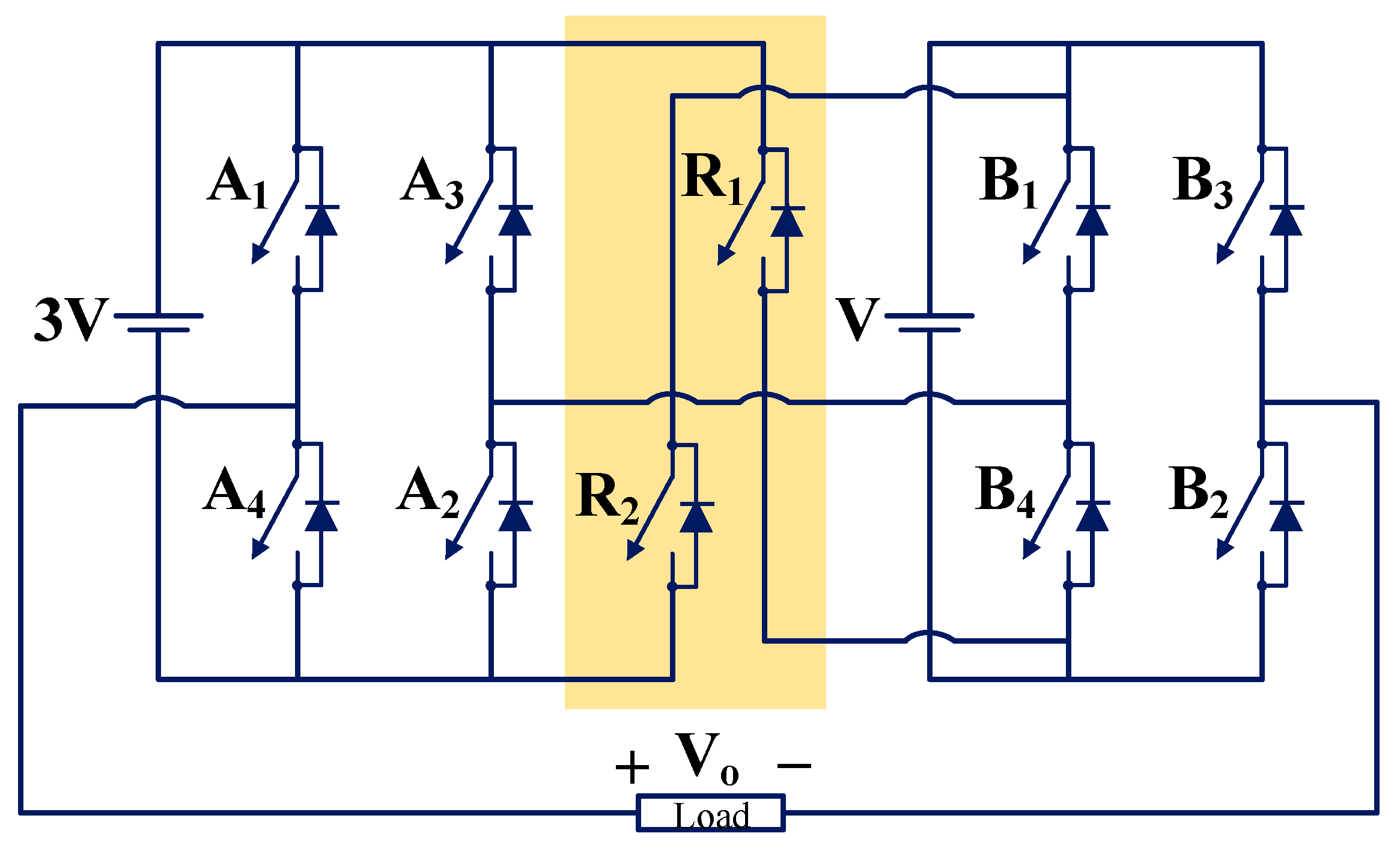
3.1.20. TP24 and TP25
3.1.21. TP26
3.1.22. TP27 and TP28
3.1.23. TP29
3.1.24. TP30
3.1.25. TP31
3.1.26. TP32
3.1.27. TP33
3.1.28. TP34
3.1.29. TP35
3.1.30. TP36
3.1.31. TP37
3.1.32. TP38
3.1.33. TP39
3.1.34. TP40
3.1.35. TP41
3.1.36. TP42
3.1.37. TP43
3.1.38. TP44
3.1.39. TP45
3.1.40. TP46
3.2. Single-Phase FT MLIs Based on Module
3.2.1. TP47 and TP48
3.2.2. TP49
- High voltage stress is exerted on healthy switches in case of fault [80].
- Higher conduction losses.
- Higher cost.
3.2.3. TP50 and TP51
3.2.4. TP52
3.2.5. TP53
4. Comparison of Recently Developed Single-Phase FT MLI Topologies
4.1. Level to Switch Count Ratio (LSCR)
4.2. Component Count to Level Ratio (CCLR)
4.3. Total Standing Voltage (TSV) and Cost Function (CF)
4.4. Fault Tolerance Factor and Complete Fault Tolerance Factor
- (i)
- When TSV is not considered,
- (ii)
- When TSV is considered,
5. Simulation and Experimental Results of a FT MLI
5.1. Nearest Level Control
5.2. Simulation Results and Discussion
5.2.1. Single-Switch OC Fault
5.2.2. Multiple-Switch OC Fault
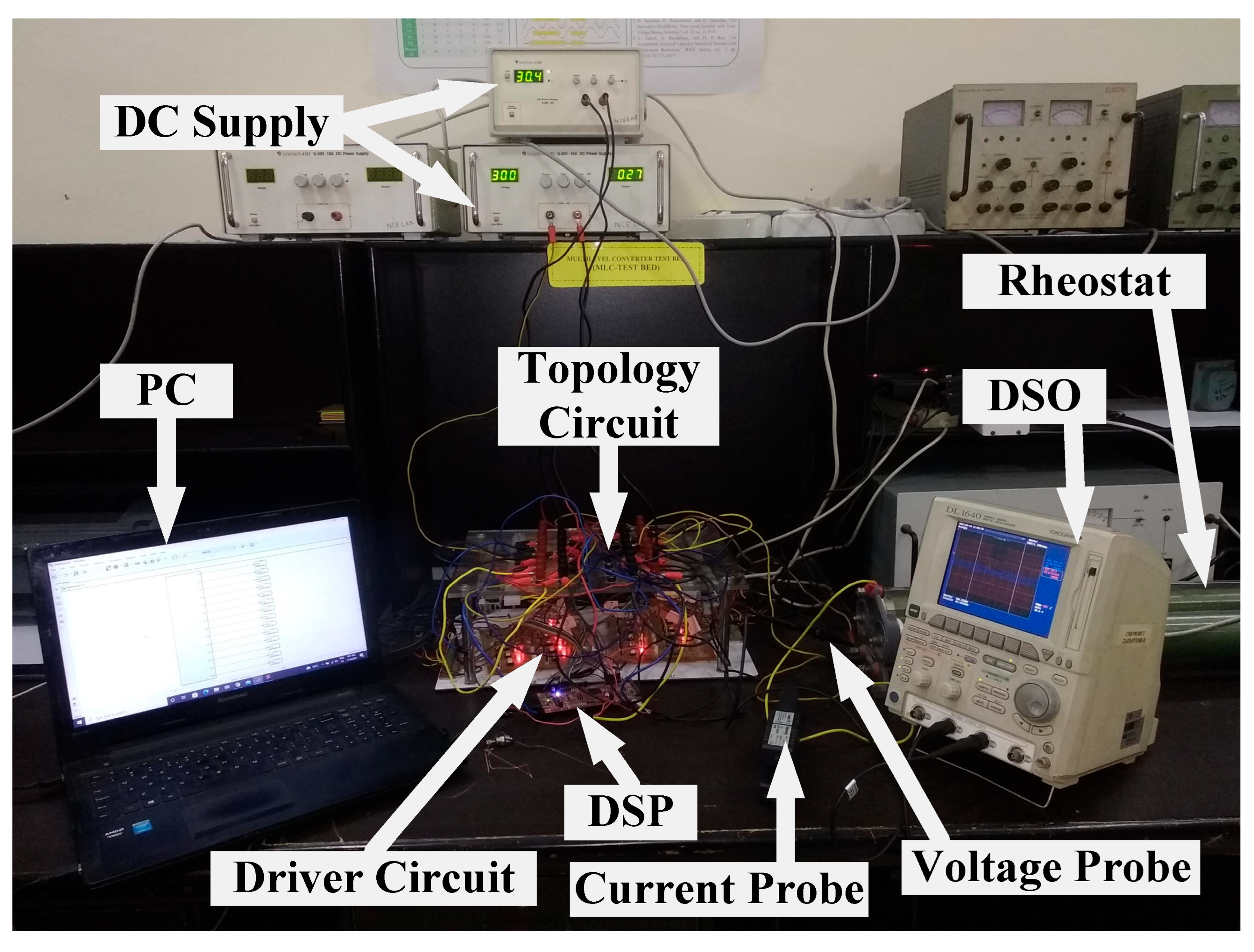
5.3. Experimental Results and Discussion
5.3.1. Single-Switch OC Fault
5.3.2. Multiple-Switch OC Fault
6. Conclusions
- There are relatively few single-phase FT MLI topologies designed to handle multiple-switch OC and/or SC faults, owing to the fact that a majority of single-phase FT MLI topologies are only appropriate for single-switch OC and/or SC faults. The development of single-phase FT MLI topologies capable of handling multiple-switch faults is an area that requires further study.
- It has been observed that redundant switches or redundant legs of FT MLIs have zero percent utilization under normal or healthy conditions. Hence, redundant switches remain non-operational under healthy conditions and increase the MLI cost. The development of FT MLI topologies where all switches operate under healthy conditions is an area that requires further investigation.
- Redundant switches or redundant legs of FT MLIs only operate under faulty condition. If redundant switches were to participate during times of overload current under healthy conditions, the thermal stress on the main inverter’s switches would be significantly reduced. Hence, the FT MLI topology would be more reliable and longer lasting. Few works in the literature analyzed the overload capability characteristics of redundant-leg or redundant-switch-based FT MLIs. Further investigation can be performed on this type of MLIs.
- Some FT MLI topologies are unable to preserve output rated voltage post-fault. Hence, topologies use a step-up transformer to maintain the output rated voltage. This will increase the cost and size of the system. The development of FT MLI topologies where output rated voltage can be achieved post-fault under the maximum number of switch fault occurrences is an area that requires further study.
- The development of FT MLI topologies where output power and efficiency can be achieved post-fault similar to pre-fault condition is an area that requires further investigation.
- Most of the FT MLI topologies in the literature focused on the switch fault. Very few works in the literature analyzed the capacitor and DC source failures in FT MLIs. The design of new FT MLI topologies that ensure operational continuity in the event of a capacitor and/or source failure requires further investigation.
- Few FT MLIs that can be extended for the “N” number of voltage levels are reported in the literature. New FT MLI topologies that can be extended to higher voltage levels for high-voltage applications require further investigation.
Author Contributions
Funding
Acknowledgments
Conflicts of Interest
References
- Salem, A.; Van Khang, H.; Robbersmyr, K.G.; Norambuena, M.; Rodriguez, J. Voltage Source Multilevel Inverters with Reduced Device Count: Topological Review and Novel Comparative Factors. IEEE Trans. Power Electron. 2021, 36, 2720–2747. [Google Scholar] [CrossRef]
- Kouro, S.; Malinowski, M.; Gopakumar, K.; Pou, J.; Franquelo, L.G.; Wu, B.; Rodriguez, J.; Perez, M.A.; Leon, J.I. Recent Advances and Industrial Applications of Multilevel Converters. IEEE Trans. Ind. Electron. 2010, 57, 2553–2580. [Google Scholar] [CrossRef]
- Nistane, T.J.; Sahu, L.K.; Jalhotra, M.; Gautam, S.P. Single and multiple switch fault-tolerance capabilities in a hybrid five-level inverter topology. IET Power Electron. 2020, 13, 1257–1266. [Google Scholar] [CrossRef]
- Bana, P.R.; Panda, K.P.; Naayagi, R.T.; Siano, P.; Panda, G. Recently Developed Reduced Switch Multilevel Inverter for Renewable Energy Integration and Drives Application: Topologies, Comprehensive Analysis and Comparative Evaluation. IEEE Access 2019, 7, 54888–54909. [Google Scholar] [CrossRef]
- Daher, S.; Schmid, J.; Antunes, F.L.M. Multilevel Inverter Topologies for Stand-Alone PV Systems. IEEE Trans. Ind. Electron. 2008, 55, 2703–2712. [Google Scholar] [CrossRef]
- Xiao, B.; Hang, L.; Mei, J.; Riley, C.; Tolbert, L.M.; Ozpineci, B. Modular Cascaded H-Bridge Multilevel PV Inverter with Distributed MPPT for Grid-Connected Applications. IEEE Trans. Ind. Appl. 2015, 51, 1722–1731. [Google Scholar] [CrossRef]
- Zhang, X.; Zhao, T.; Mao, W.; Tan, D.; Chang, L. Multilevel Inverters for Grid-Connected Photovoltaic Applications: Examining Emerging Trends. IEEE Power Electron. Mag. 2018, 5, 32–41. [Google Scholar] [CrossRef]
- Madhukar Rao, A.; Sivakumar, K. A Fault-Tolerant Single-Phase Five-Level Inverter for Grid-Independent PV Systems. IEEE Trans. Ind. Electron. 2015, 62, 7569–7577. [Google Scholar] [CrossRef]
- Joseph, A.; Chelliah, T.R. A Review of Power Electronic Converters for Variable Speed Pumped Storage Plants: Configurations, Operational Challenges, and Future Scopes. IEEE J. Emerg. Sel. Top. Power Electron. 2018, 6, 103–119. [Google Scholar] [CrossRef]
- Hoon, Y.; Radzi, M.A.M.; Hassan, M.K.; Mailah, N.F. Operation of Three-Level Inverter-Based Shunt Active Power Filter Under Nonideal Grid Voltage Conditions with Dual Fundamental Component Extraction. IEEE Trans. Power Electron. 2018, 33, 7558–7570. [Google Scholar] [CrossRef]
- Varschavsky, A.; Dixon, J.; Rotella, M.; Moran, L. Cascaded Nine-Level Inverter for Hybrid-Series Active Power Filter, Using Industrial Controller. IEEE Trans. Ind. Electron. 2010, 57, 2761–2767. [Google Scholar] [CrossRef]
- Soto, D.; Green, T. A comparison of high-power converter topologies for the implementation of FACTS controllers. IEEE Trans. Ind. Electron. 2002, 49, 1072–1080. [Google Scholar] [CrossRef] [Green Version]
- Nair, R.N.; Gopakumar, K.; Franquelo, L.G. A Very High Resolution Stacked Multilevel Inverter Topology for Adjustable Speed Drives. IEEE Trans. Ind. Electron. 2018, 65, 2049–2056. [Google Scholar] [CrossRef]
- Ghat, M.B.; Shukla, A. A New H-Bridge Hybrid Modular Converter (HBHMC) for HVDC Application: Operating Modes, Control, and Voltage Balancing. IEEE Trans. Power Electron. 2018, 33, 6537–6554. [Google Scholar] [CrossRef]
- Jung, J.-J.; Cui, S.; Lee, J.-H.; Sul, S.-K. A New Topology of Multilevel VSC Converter for a Hybrid HVDC Transmission System. IEEE Trans. Power Electron. 2017, 32, 4199–4209. [Google Scholar] [CrossRef]
- El-Hosainy, A.; Hamed, H.A.; Azazi, H.Z.; El-Kholy, E. A review of multilevel inverter topologies, control techniques, and applications. In Proceedings of the 2017 Nineteenth International Middle East Power Systems Conference (MEPCON), Cairo, Egypt, 19–21 December 2017; pp. 1265–1275. [Google Scholar] [CrossRef]
- Rodriguez, J.; Lai, J.-S.; Peng, F.Z. Multilevel inverters: A survey of topologies, controls, and applications. IEEE Trans. Ind. Electron. 2002, 49, 724–738. [Google Scholar] [CrossRef] [Green Version]
- Franquelo, L.G.; Rodriguez, J.; Leon, J.I.; Kouro, S.; Portillo, R.; Prats, M.A. The age of multilevel converters arrives. IEEE Ind. Electron. Mag. 2008, 2, 28–39. [Google Scholar] [CrossRef] [Green Version]
- Vijeh, M.; Rezanejad, M.; Samadaei, E.; Bertilsson, K. A General Review of Multilevel Inverters Based on Main Submodules: Structural Point of View. IEEE Trans. Power Electron. 2019, 34, 9479–9502. [Google Scholar] [CrossRef]
- Debnath, S.; Qin, J.; Bahrani, B.; Saeedifard, M.; Barbosa, P. Operation, Control, and Applications of the Modular Multilevel Converter: A Review. IEEE Trans. Power Electron. 2015, 30, 37–53. [Google Scholar] [CrossRef]
- Choi, U.-M.; Blaabjerg, F.; Lee, K.-B. Study and Handling Methods of Power IGBT Module Failures in Power Electronic Converter Systems. IEEE Trans. Power Electron. 2015, 30, 2517–2533. [Google Scholar] [CrossRef]
- Kumar, G.K.; Elangovan, D. Review on fault-diagnosis and fault-tolerance for DC–DC converters. IET Power Electron. 2020, 13, 1–13. [Google Scholar] [CrossRef]
- Dewangan, N.K.; Prakash, T.; Tandekar, J.K.; Gupta, K.K. Open-circuit fault-tolerance in multilevel inverters with reduced component count. Electr. Eng. 2020, 102, 409–419. [Google Scholar] [CrossRef]
- Gupta, K.K.; Ranjan, A.; Bhatnagar, P.; Sahu, L.K.; Jain, S. Multilevel Inverter Topologies with Reduced Device Count: A Review. IEEE Trans. Power Electron. 2016, 31, 135–151. [Google Scholar] [CrossRef]
- Krishnachaitanya, D.; Chitra, A. Quantitative Analysis of Asymmetric Multilevel Inverters with Reduced Device Count From Reliability and Cost Function Perspective—A Review. IEEE Trans. Power Electron. 2021, 36, 11068–11086. [Google Scholar] [CrossRef]
- Omer, P.; Kumar, J.; Surjan, B.S. A Review on Reduced Switch Count Multilevel Inverter Topologies. IEEE Access 2020, 8, 22281–22302. [Google Scholar] [CrossRef]
- Prabaharan, N.; Palanisamy, K. A comprehensive review on reduced switch multilevel inverter topologies, modulation techniques and applications. Renew. Sustain. Energy Rev. 2017, 76, 1248–1282. [Google Scholar] [CrossRef]
- Dewangan, N.K.; Gupta, S.; Gupta, K.K. Approach to synthesis of fault tolerant reduced device count multilevel inverters (FT RDC MLIs). IET Power Electron. 2019, 12, 476–482. [Google Scholar] [CrossRef]
- Firdous, Z.; Rehman, H.; Tariq, M.; Sarwar, A. Investigation of Fault-Tolerant Capabilities of a Reduced Device Multilevel Inverter. In Proceedings of the 2022 2nd International Conference on Emerging Frontiers in Electrical and Electronic Technologies (ICEFEET), Patna, India, 24–25 June 2022; pp. 1–5. [Google Scholar] [CrossRef]
- Zhang, W.; Xu, D.; Enjeti, P.N.; Li, H.; Hawke, J.T.; Krishnamoorthy, H.S. Survey on Fault-Tolerant Techniques for Power Electronic Converters. IEEE Trans. Power Electron. 2014, 29, 6319–6331. [Google Scholar] [CrossRef]
- Gautam, S.P.; Kumar, L.; Gupta, S.; Agrawal, N. A Single-Phase Five-Level Inverter Topology with Switch Fault-Tolerance Capabilities. IEEE Trans. Ind. Electron. 2017, 64, 2004–2014. [Google Scholar] [CrossRef]
- Aleenejad, M.; Jafarishiadeh, S.; Mahmoudi, H.; Ahmadi, R. Reduced number of auxiliary H-bridge power cells for post-fault operation of three phase cascaded H-bridge inverter. IET Power Electron. 2019, 12, 2923–2931. [Google Scholar] [CrossRef]
- Lezana, P.; Pou, J.; Meynard, T.A.; Rodriguez, J.; Ceballos, S.; Richardeau, F. Survey on Fault Operation on Multilevel Inverters. IEEE Trans. Ind. Electron. 2010, 57, 2207–2218. [Google Scholar] [CrossRef] [Green Version]
- Aly, M.; Ahmed, E.M.; Shoyama, M. A New Single-Phase Five-Level Inverter Topology for Single and Multiple Switches Fault Tolerance. IEEE Trans. Power Electron. 2018, 33, 9198–9208. [Google Scholar] [CrossRef]
- Chappa, A.; Gupta, S.; Sahu, L.K.; Gupta, K.K. A Fault-Tolerant Multilevel Inverter Topology with Preserved Output Power and Voltage Levels Under Pre- and Postfault Operation. IEEE Trans. Ind. Electron. 2021, 68, 5756–5764. [Google Scholar] [CrossRef]
- Katebi, R.; He, J.; Weise, N. Investigation of Fault-Tolerant Capabilities in an Advanced Three-Level Active T-Type Converter. IEEE J. Emerg. Sel. Top. Power Electron. 2019, 7, 446–457. [Google Scholar] [CrossRef] [Green Version]
- Dewangan, N.K.; Tailor, T.K.; Agrawal, R.; Bhatnagar, P.; Gupta, K.K. A multilevel inverter structure with open circuit fault-tolerant capability. Electr. Eng. 2021, 103, 1613–1628. [Google Scholar] [CrossRef]
- Asif, M.; Tariq, M.; Sarwar, A.; Hussan, R.; Ahmad, S.; Mihet-Popa, L.; Mohamed, A.S.N. A Robust Multilevel Inverter Topology for Operation under Fault Conditions. Electronics 2021, 10, 3099. [Google Scholar] [CrossRef]
- Sarwar, M.I.; Sarwar, A.; Farooqui, S.A.; Tariq, M.; Fahad, M.; Beig, A.R.; Alamri, B. A Hybrid Nearest Level Combined with PWM Control Strategy: Analysis and Implementation on Cascaded H-Bridge Multilevel Inverter and its Fault Tolerant Topology. IEEE Access 2021, 9, 44266–44282. [Google Scholar] [CrossRef]
- Chappa, A.; Gupta, S.; Sahu, L.K.; Gupta, K.K. Resilient multilevel inverter topology with improved reliability. IET Power Electron. 2020, 13, 3384–3395. [Google Scholar] [CrossRef]
- Jalhotra, M.; Kumar, L.; Gautam, S.P.; Gupta, S. Development of fault-tolerant MLI topology. IET Power Electron. 2018, 11, 1416–1424. [Google Scholar] [CrossRef]
- Peddapati, S.; Prasadarao, K.V.S. A New Fault-Tolerant Multilevel Inverter Structure with Reduced Device Count and Low Total Standing Voltage. IEEE Trans. Power Electron. 2022, 37, 8333–8344. [Google Scholar] [CrossRef]
- Mirafzal, B. Survey of Fault-Tolerance Techniques for Three-Phase Voltage Source Inverters. IEEE Trans. Ind. Electron. 2014, 61, 5192–5202. [Google Scholar] [CrossRef]
- Correa, P.; Pacas, M.; Rodriguez, J. Modulation Strategies for Fault-Tolerant Operation of H-Bridge Multilevel Inverters. In Proceedings of the 2006 IEEE International Symposium on Industrial Electronics, Montreal, QC, Canada, 9–13 July 2006; pp. 1589–1594. [Google Scholar] [CrossRef]
- Choi, U.-M.; Blaabjerg, F. A novel active T-type three-level converter with open-circuit fault-tolerant control. In Proceedings of the 2015 IEEE Energy Conversion Congress and Exposition (ECCE), Montreal, QC, Canada, 20–24 September 2015; pp. 4765–4772. [Google Scholar] [CrossRef]
- Sahoo, M.; Keerthipati, S. Fault tolerant three-level boost inverter with reduced source and LC count. IET Power Electron. 2018, 11, 399–405. [Google Scholar] [CrossRef]
- Do, D.-T.; Nguyen, M.-K.; Quach, T.-H.; Tran, V.-T.; Blaabjerg, F.; Vilathgamuwa, D.M. A PWM Scheme for a Fault-Tolerant Three-Level Quasi-Switched Boost T-Type Inverter. IEEE J. Emerg. Sel. Top. Power Electron. 2020, 8, 3029–3040. [Google Scholar] [CrossRef] [Green Version]
- Kumar, D.; Nema, R.K.; Gupta, S. Investigation of fault-tolerant capabilities of some recent multilevel inverter topologies. Int. J. Electron. 2021, 108, 1957–1976. [Google Scholar] [CrossRef]
- Rehman, H.; Iqbal, H.; Tariq, M.; Sarwar, A.; Sarfraz, M.; Gupta, G.M.; Maswood, A.I. Fault Tolerant Operation in Multilevel Inverter for More Electric Aircraft. In Proceedings of the 2022 2nd International Conference on Emerging Frontiers in Electrical and Electronic Technologies (ICEFEET), Patna, India, 24–25 June 2022; pp. 1–6. [Google Scholar] [CrossRef]
- Sadanala, C.; Pattnaik, S.; Singh, V.P. Fault tolerant architecture of an efficient five-level multilevel inverter with overload capability characteristics. IET Power Electron. 2020, 13, 368–376. [Google Scholar] [CrossRef]
- Jalhotra, M.; Sahu, L.K.; Gupta, S.; Gautam, S.P. Highly Resilient Fault-Tolerant Topology of Single-Phase Multilevel Inverter. IEEE J. Emerg. Sel. Top. Power Electron. 2021, 9, 1915–1922. [Google Scholar] [CrossRef]
- Siddique, M.D.; Rawa, M.; Mekhilef, S.; Shah, N.M. A new cascaded asymmetrical multilevel inverter based on switched dc voltage sources. Int. J. Electr. Power Energy Syst. 2021, 128, 106730. [Google Scholar] [CrossRef]
- Prasadarao, K.V.S.; Peddapati, S.; Naresh, S. A New Fault-Tolerant MLI—Investigating Its Skipped Level Performance. IEEE Trans. Ind. Electron. 2022, 69, 1432–1442. [Google Scholar] [CrossRef]
- Saketi, S.K.; Chaturvedi, P.; Yadeo, D.; Atkar, D. Loss study and reliability analysis of a new reconfigurable fault-tolerant multilevel inverter topology. IET Power Electron. 2020, 13, 4291–4303. [Google Scholar] [CrossRef]
- Reddy, K.N.; Pradabane, S. Modified H-bridge inverter based fault-tolerant multilevel topology for open-end winding induction motor drive. IET Power Electron. 2019, 12, 2810–2820. [Google Scholar] [CrossRef]
- Fahad, M.; Tariq, M.; Sarwar, A.; Modabbir, M.; Zaid, M.; Satpathi, K.; Hussan, R.; Tayyab, M.; Alamri, B.; Alahmadi, A. Asymmetric Multilevel Inverter Topology and Its Fault Management Strategy for High-Reliability Applications. Energies 2021, 14, 4302. [Google Scholar] [CrossRef]
- Fahad, M.; Alsultan, M.; Ahmad, S.; Sarwar, A.; Tariq, M.; Khan, I.A. Reliability Analysis and Fault-Tolerant Operation in a Multilevel Inverter for Industrial Application. Electronics 2021, 11, 98. [Google Scholar] [CrossRef]
- Maddugari, S.K.; Borghate, V.B.; Sabyasachi, S.; Karasani, R.R. A fault tolerant cascaded multilevel inverter topology for open circuit faults in switches. In Proceedings of the 2017 IEEE Transportation Electrification Conference, ITEC-India, Pune, India, 13–15 December 2017; pp. 1–5. [Google Scholar] [CrossRef]
- Maddugari, S.K.; Borghate, V.B.; Sabyasachi, S.; Karasani, R.R. A Linear-Generator-Based Wave Power Plant Model Using Reliable Multilevel Inverter. IEEE Trans. Ind. Appl. 2019, 55, 2964–2972. [Google Scholar] [CrossRef]
- Kumar, M.S.; Borghate, V.B.; Karasani, R.R.; Sabyasachi, S.; Suryawanshi, H.M. A fault-tolerant modular multilevel inverter topology. Int. J. Circuit Theory Appl. 2018, 46, 1028–1043. [Google Scholar] [CrossRef]
- Airineni, M.R.; Bhimireddy, P.R.; Sahoo, M.; Keerthipati, S. A multi-string fault-tolerant multilevel inverter configuration for off-grid photovoltaic applications. Int. Trans. Electr. Energy Syst. 2021, 31, e12803. [Google Scholar] [CrossRef]
- Choupan, R.; Golshannavaz, S.; Nazarpour, D.; Barmala, M. A new structure for multilevel inverters with fault-tolerant capability against open circuit faults. Electr. Power Syst. Res. 2019, 168, 105–116. [Google Scholar] [CrossRef]
- Kumar, V.; Singh, S.; Jain, S. A Reduced Switch Count Symmetric T-type Multilevel Inverter with Single and Multiple Switch Open Circuit Fault Tolerant Capabilities. IETE J. Res. 2022, 1–23. [Google Scholar] [CrossRef]
- Maddugari, S.K.; Borghate, V.B.; Sabyasachi, S. A reliable and efficient single-phase modular multilevel inverter topology. Int. J. Circuit Theory Appl. 2019, 47, 718–737. [Google Scholar] [CrossRef]
- Soni, N.; Borghate, V.B.; Maddugari, S.K.; Ambhore, D.; Sabyasachi, S. A Simple Fault Tolerant Multilevel Inverter Topology. In Proceedings of the 2018 8th IEEE India International Conference on Power Electronics (IICPE), Jaipur, India, 13–15 December 2018. [Google Scholar] [CrossRef]
- Sulake, N.R.; Pranupa, S.; Indira, M.S. Cross Connected Source based Reduced Switch Count Multilevel Inverter Topology with Fault Tolerance. In Proceedings of the 2019 Global Conference for Advancement in Technology (GCAT), Bangalore, India, 18–20 October 2019. [Google Scholar] [CrossRef]
- Kumar, D.; Nema, R.K.; Gupta, S. Development of a novel fault-tolerant reduced device count T-type multilevel inverter topology. Int. J. Electr. Power Energy Syst. 2021, 132, 107185. [Google Scholar] [CrossRef]
- Kumar, D.; Nema, R.K.; Gupta, S. Development of fault-tolerant reduced device version with switched-capacitor based multilevel inverter topologies. Int. Trans. Electr. Energy Syst. 2021, 31, e12893. [Google Scholar] [CrossRef]
- Hassani, M.; Azimi, E.; Khodaparast, A.; Adabi, J.; Pouresmaeil, E. Fault-Tolerant Operation Strategy for Reliability Improvement of a Switched-Capacitor Multilevel Inverter. IEEE Trans. Ind. Electron. 2022, 69, 9916–9926. [Google Scholar] [CrossRef]
- Kumar, V.; Singh, S.; Jain, S. Fault Tolerant T-Type Cross Connected Source Nine Level Inverter. In Proceedings of the PIICON 2020—9th IEEE Power India International Conference, Sonepat, India, 28 February–1 March 2020. [Google Scholar] [CrossRef]
- Jalhotra, M.; Gautam, S.P.; Kumar, L.; Gupta, S. Single and multi switch fault tolerant topology of multi level inverter. In Proceedings of the 2018 IEEE International Conference on Power, Instrumentation, Control and Computing, PICC 2018, Thrissur, India, 18–20 January 2018. [Google Scholar] [CrossRef]
- Ponnada, G.N.; Babu, C.S.; Satyanarayana, S.; Biswas, S.S. Fault Detection and Tolerance of a Hybrid Five Level Inverter. Iran. J. Sci. Technol. Trans. Electr. Eng. 2021, 45, 895–904. [Google Scholar] [CrossRef]
- Maddugari, S.K.; Borghate, V.B.; Sabyasachi, S.; Sanjeevini, G. A Reliable Fault Tolerant Inverter. In Proceedings of the 2020 IEEE 1st International Conference on Smart Technologies for Power, Energy and Control, STPEC, Nagpur, India, 25–26 September 2020. [Google Scholar] [CrossRef]
- Kumar, M.S.; Borghate, V.B.; Sabyasachi, S. A Generalized Fault Tolerant Multilevel Inverter for Switch Open-Circuit Faults. In Proceedings of the 2018 IEEE International Conference on Power Electronics, Drives and Energy Systems, PEDES, Chennai, India, 18–21 December 2018. [Google Scholar] [CrossRef]
- Manik; Gautam, S.P.; Kumar, L.; Gupta, S.; Chander, A.H. Reliability Analysis of a Novel Fault Tolerant Multilevel Inverter Topology. In Proceedings of the IECON 2018—44th Annual Conference of the IEEE Industrial Electronics Society, Washington, DC, USA, 21–23 October 2018; pp. 1460–1465. [Google Scholar] [CrossRef]
- Saketi, S.K.; Chaturvedi, P.; Yadeo, D. A New Fault Tolerant Single Phase 5-Level Inverter Topology. In Proceedings of the India International Conference on Power Electronics, IICPE, Jaipur, India, 13–15 December 2018. [Google Scholar] [CrossRef]
- Dewangan, N.; Jalhotra, M.; Sahu, L.K.; Gautam, S.P.; Gupta, S. Fault Tolerant Analysis of Single Phase Multilevel Inverter. In Proceedings of the 2018 IEEE International Conference on Power Electronics, Drives and Energy Systems, PEDES, Chennai, India, 18–21 December 2018. [Google Scholar] [CrossRef]
- Zamiri, E.; Vosoughi, N.; Hosseini, S.H.; Barzegarkhoo, R.; Sabahi, M. A New Cascaded Switched-Capacitor Multilevel Inverter Based on Improved Series–Parallel Conversion with Less Number of Components. IEEE Trans. Ind. Electron. 2016, 63, 3582–3594. [Google Scholar] [CrossRef]
- Kumar, D.; Nema, R.K.; Gupta, S.; Nema, S.; Dewangan, N.K. A New Fault-Tolerant Multilevel Inverter Topology with Enhanced Reliability for PV Application. Arab. J. Sci. Eng. 2022, 47, 14841–14858. [Google Scholar] [CrossRef]
- Jahan, H.K.; Panahandeh, F.; Abapour, M.; Tohidi, S. Reconfigurable Multilevel Inverter with Fault-Tolerant Ability. IEEE Trans. Power Electron. 2018, 33, 7880–7893. [Google Scholar] [CrossRef]
- Haji-Esmaeili, M.M.; Naseri, M.; Khoun-Jahan, H.; Abapour, M. Fault-tolerant structure for cascaded H-bridge multilevel inverter and reliability evaluation. IET Power Electron. 2017, 10, 59–70. [Google Scholar] [CrossRef]
- Mhiesan, H.; Wei, Y.; Siwakoti, Y.P.; Mantooth, H.A. A Fault-Tolerant Hybrid Cascaded H-Bridge Multilevel Inverter. IEEE Trans. Power Electron. 2020, 35, 12702–12715. [Google Scholar] [CrossRef]
- Agarwal, S.; Kapoor, A.K. Full-Fault-Tolerant Single-Phase 13-Level Cascaded Multilevel Inverter with Modified H-Bridge Modules. In Proceedings of the 2018 International Conference on Computing, Power and Communication Technologies, GUCON, Greater Noida, India, 28–29 September 2018; pp. 941–945. [Google Scholar] [CrossRef]
- Patel, M.D.; Pandya, D.J.; Raval, D.Y.; Yagnik, N.Y. Fault-Tolerant Structure for Cascaded H-bridge Multilevel Inverter using Relays. In Proceedings of the 8th International Conference on Computation of Power, Energy, Information and Communication, ICCPEIC 2019, Melmaruvathur, India, 27–28 March 2019; pp. 8–13. [Google Scholar] [CrossRef]
- Hasan, M.; Mekhilef, S.; Ahmed, M. Three-phase hybrid multilevel inverter with less power electronic components using space vector modulation. IET Power Electron. 2014, 7, 1256–1265. [Google Scholar] [CrossRef] [Green Version]
- Salem, A.; Ahmed, E.M.; Orabi, M.; Ahmed, M. New Three-Phase Symmetrical Multilevel Voltage Source Inverter. IEEE J. Emerg. Sel. Top. Circuits Syst. 2015, 5, 430–442. [Google Scholar] [CrossRef]
- Hosseinzadeh, M.A.; Sarebanzadeh, M.; Rivera, M.; Babaei, E.; Wheeler, P. A Reduced Single-Phase Switched-Diode Cascaded Multilevel Inverter. IEEE J. Emerg. Sel. Top. Power Electron. 2021, 9, 3556–3569. [Google Scholar] [CrossRef]
- Sarwer, Z.; Siddique, M.D.; Iqbal, A.; Sarwar, A.; Mekhilef, S. An improved asymmetrical multilevel inverter topology with reduced semiconductor device count. Int. Trans. Electr. Energy Syst. 2020, 30, e12587. [Google Scholar] [CrossRef]
- Fahad, M.; Siddique, M.D.; Iqbal, A.; Sarwar, A.; Mekhilef, S. Implementation and Analysis of a 15-Level Inverter Topology with Reduced Switch Count. IEEE Access 2021, 9, 40623–40634. [Google Scholar] [CrossRef]
- Siddique, M.D.; Iqbal, A.; Sarwar, A.; Mekhilef, S. Analysis and implementation of a new asymmetric double H-bridge multilevel inverter. Int. J. Circuit Theory Appl. 2021, 49, 4012–4026. [Google Scholar] [CrossRef]
- Bin Arif, M.S.; Mustafa, U.; Ayob, S.B.M.; Rodriguez, J.; Nadeem, A.; Abdelrahem, M. Asymmetrical 17-Level Inverter Topology with Reduced Total Standing Voltage and Device Count. IEEE Access 2021, 9, 69710–69723. [Google Scholar] [CrossRef]
- Hussan, R.; Sarwar, A.; Siddique, M.D.; Mekhilef, S.; Ahmad, S.; Sharaf, M.; Zaindin, M.; Firdausi, M. A Novel Switched-Capacitor Multilevel Inverter Topology for Energy Storage and Smart Grid Applications. Electronics 2020, 9, 1703. [Google Scholar] [CrossRef]
- Tayyab, M.; Sarwar, A.; Khan, I.; Tariq, M.; Hussan, R.; Murshid, S.; Alhosaini, W. A Single Source Switched-Capacitor 13-Level Inverter with Triple Voltage Boosting and Reduced Component Count. Electronics 2021, 10, 2321. [Google Scholar] [CrossRef]
- Hu, P.; Jiang, D. A Level-Increased Nearest Level Modulation Method for Modular Multilevel Converters. IEEE Trans. Power Electron. 2015, 30, 1836–1842. [Google Scholar] [CrossRef]
- Fahad, M.; Tariq, M.; Faizan, M.; Ali, A.; Sarwar, A.; Tafti, H.D.; Ahmad, S.; Mohamed, A.S.N. A Dual Source Switched-Capacitor Multilevel Inverter with Reduced Device Count. Electronics 2021, 11, 67. [Google Scholar] [CrossRef]


| Group | Reference | Topology | FT Solution | X1 | X2 | X3 | X4 | X5 | X6 | X7 | X8 | X9 | X11 | X12 | LSCR | LCCR |
|---|---|---|---|---|---|---|---|---|---|---|---|---|---|---|---|---|
| I | [34] | TP5 | LA | 5 | 0 | 2 | 0 | 14 | 4 | 4 | 4 | 3 | 0 | 14 | 0.3571 | 0.1316 |
| [3] | TP6 | LA | 5 | 0 | 1 | 1 | 12 | 0 | 0 | 3 | 4 | 0 | 12 | 0.4167 | 0.1923 | |
| [31] | TP8 | IHR | 5 | 1 | 1 | 1 | 8 | 2 | 0 | 3 | 3 | 0 | 7 | 0.6250 | 0.2632 | |
| [31] | TP9 | LA | 5 | 3 | 1 | 1 | 14 | 2 | 0 | 3 | 4 | 0 | 11 | 0.3571 | 0.1724 | |
| [28] | TP1 | SA | 5 | 1 | 2 | 0 | 8 | 0 | 0 | 3 | 4 | 0 | 7 | 0.6250 | 0.2941 | |
| [28] | TP2 | SA | 5 | 2 | 2 | 0 | 8 | 0 | 0 | 3 | 3 | 0 | 6 | 0.6250 | 0.3125 | |
| [48] | TP3 | SA | 5 | 0 | 1 | 1 | 8 | 0 | 0 | 3 | 3 | 0 | 8 | 0.6250 | 0.2778 | |
| [37] | TP12 | IHR | 5 | 0 | 2 | 0 | 9 | 0 | 0 | 5 | 5 | 0 | 9 | 0.5556 | 0.2500 | |
| [8] | TP17 | SA | 5 | 1 * | 2 | 0 | 8 | 2 | 0 | 3 | 3 | 0 | 7 | 0.6250 | 0.2632 | |
| [50] | TP10 | LA | 5 | 1 | 1 | 1 | 14 | 2 | 0 | 4 | 4 | 0 | 13 | 0.3571 | 0.1613 | |
| [54] | TP19 | SA | 5 | 3 * | 2 | 0 | 12 | 0 | 9 | 3 | 3 | 0 | 9 | 0.4167 | 0.1563 | |
| [51] | TP11 | LA | 5 | 0 | 1 | 1 | 12 | 2 | 4 | 4 | 3 | 0 | 12 | 0.4167 | 0.1563 | |
| [38] | TP23 | SA | 5 | 0 | 2 | 0 | 9 | 0 | 0 | 3 | 3 | 0 | 9 | 0.5556 | 0.2500 | |
| [58] | TP26 | IHR | 5 | 2 * | 2 | 0 | 8 | 0 | 0 | 3 | 3 | 0 | 6 | 0.6250 | 0.3125 | |
| [64] | TP32 | IHR | 5 | 2 * | 2 | 0 | 8 | 0 | 0 | 3 | 3 | 0 | 6 | 0.6250 | 0.3125 | |
| [67] | TP35 | IHR | 5 | 2 | 1 | 2 | 8 | 0 | 0 | 3 | 3 | 0 | 6 | 0.6250 | 0.2942 | |
| [72] | TP40 | LA | 5 | 0 | 1 | 2 | 14 | 6 | 0 | 3 | 3 | 0 | 14 | 0.3571 | 0.1351 | |
| [74] | TP42 | IHR | 5 | 1 | 2 | 0 | 8 | 0 | 0 | 4 | 4 | 0 | 7 | 0.6250 | 0.2941 | |
| [76] | TP44 | IHR | 5 | 1 * | 2 | 0 | 6 | 0 | 0 | 3 | 3 | 2 | 5 | 0.8333 | 0.3333 | |
| II | [48] | TP4 | SA | 7 | 3 * | 2 | 2 | 12 | 0 | 0 | 3 | 3 | 0 | 9 | 0.5833 | 0.2800 |
| [62] | TP30 | IHR | 7 | 2 | 3 | 0 | 12 | 0 | 0 | 4 | 4 | 0 | 10 | 0.5833 | 0.2800 | |
| [65] | TP33A | IHR | 7 | 4 | 3 | 0 | 12 | 0 | 0 | 3 | 4 | 0 | 8 | 0.5833 | 0.3043 | |
| [66] | TP34 | IHR | 7 | 0 | 3 | 0 | 8 | 0 | 0 | 4 | 4 | 0 | 8 | 0.8750 | 0.3684 | |
| [68] | TP36 | SA | 7 | 3 | 2 | 2 | 12 | 0 | 0 | 4 | 5 | 0 | 9 | 0.5833 | 0.2800 | |
| [73] | TP41 | IHR | 7 | 2 | 3 | 0 | 8 | 0 | 0 | 3 | 3 | 6 | 6 | 0.8750 | 0.3043 | |
| III | [35] | TP7 | LA | 9 | 0 | 2 | 2 | 16 | 0 | 0 | 5 | 5 | 0 | 16 | 0.5625 | 0.2500 |
| [39] | TP14 | SA | 9 | 0 | 2 | 0 | 10 | 0 | 0 | 4 | 4 | 0 | 10 | 0.9000 | 0.4091 | |
| [53] | TP15 | IHR | 9 | 0 | 4 | 0 | 12 | 0 | 0 | 5 | 5 | 0 | 12 | 0.7500 | 0.3214 | |
| [40] | TP18 | IHR | 9 | 3 | 2 | 1 | 12 | 0 | 0 | 3 | 3 | 0 | 9 | 0.7500 | 0.3750 | |
| [41] | TP20 | IHR | 9 | 3 | 2 | 2 | 12 | 0 | 0 | 4 | 4 | 0 | 9 | 0.7500 | 0.3600 | |
| [42] | TP24 | IHR | 9 | 0 | 4 | 0 | 12 | 0 | 0 | 5 | 5 | 0 | 12 | 0.7500 | 0.3214 | |
| [60] | TP28 | IHR | 9 | 6 | 4 | 0 | 18 | 0 | 0 | 5 | 5 | 0 | 12 | 0.5000 | 0.2647 | |
| [61] | TP29 | IHR | 9 | 2 * | 4 | 0 | 14 | 0 | 0 | 5 | 5 | 0 | 12 | 0.6428 | 0.3000 | |
| [63] | TP31 | SA | 9 | 3 | 4 | 0 | 12 | 0 | 0 | 4 | 5 | 0 | 9 | 0.7500 | 0.3600 | |
| [70] | TP38 | IHR | 9 | 2 | 4 | 0 | 12 | 0 | 0 | 5 | 5 | 0 | 10 | 0.7500 | 0.3462 | |
| [71] | TP39 | SA | 9 | 4 | 2 | 2 | 14 | 0 | 0 | 4 | 4 | 0 | 10 | 0.6428 | 0.3214 | |
| [75] | TP43 | LA | 9 | 3 | 2 | 2 | 12 | 0 | 0 | 4 | 4 | 0 | 9 | 0.7500 | 0.3600 | |
| [77] | TP45 | IHR | 9 | 0 | 2 | 2 | 13 | 0 | 0 | 3 | 3 | 0 | 13 | 0.6923 | 0.3000 | |
| [79] | TP46 | LA | 9 | 3 | 3 | 0 | 12 | 0 | 7 | 3 | 4 | 0 | 9 | 0.7500 | 0.2903 | |
| IV | [56] | TP21 | SA | 11 | 3 | 3 | 0 | 12 | 0 | 0 | 3 | 3 | 0 | 9 | 0.9167 | 0.4583 |
| V | [52] | TP13 | SA | 13 | 3 | 3 | 0 | 12 | 0 | 0 | 3 | 3 | 0 | 9 | 1.0833 | 0.5417 |
| [65] | TP33B | IHR | 13 | 4 | 3 | 0 | 12 | 0 | 0 | 3 | 4 | 0 | 8 | 1.0833 | 0.5652 | |
| VI | [57] | TP22 | IHR | 15 | 1 | 4 | 0 | 12 | 0 | 0 | 4 | 4 | 0 | 11 | 1.2500 | 0.5556 |
| [69] | TP37 | IHR | 15 | 6 | 1 | 8 | 36 | 0 | 0 | 10 | 19 | 0 | 30 | 0.4167 | 0.2000 | |
| VII | [53] | TP16 | IHR | 17 | 0 | 4 | 0 | 12 | 0 | 0 | 5 | 5 | 0 | 12 | 1.4167 | 0.6071 |
| [42] | TP25 | IHR | 17 | 0 | 4 | 0 | 12 | 0 | 0 | 5 | 5 | 0 | 12 | 1.4167 | 0.6071 |
| Group | Reference | Topology | FT Solution | X1 | X3 | X4 | X5 | X7 | X10 | X11 | X12 | LSCR | LCCR |
|---|---|---|---|---|---|---|---|---|---|---|---|---|---|
| VIII | [80] | TP47 | MB | 7 | 3 | 0 | 16 | 0 | 0 | 2 | 16 | 0.4375 | 0.1892 |
| [81] | TP49 | MB | 7 | 3 | 0 | 12 | 0 | 2 | 12 | 12 | 0.5833 | 0.1707 | |
| [82] | TP51 | MB | 7 | 3 | 4 | 16 | 6 | 0 | 0 | 16 | 0.4375 | 0.1556 | |
| [84] | TP53 | MB | 7 | 3 | 0 | 12 | 0 | 0 | 16 | 12 | 0.5833 | 0.1628 | |
| IX | [83] | TP52 | MB | 13 | 6 | 0 | 18 | 0 | 0 | 0 | 18 | 0.7222 | 0.3095 |
| X | [80] | TP48 | MB | 15 | 3 | 0 | 16 | 0 | 0 | 2 | 16 | 0.9375 | 0.4054 |
| Group | Reference | Topology | X1 | X3 | X4 | X5 | X6 | X7 | X11 | X12 | TSV (×Vdc) | TSVp.u. | CF | CFLR | ||
|---|---|---|---|---|---|---|---|---|---|---|---|---|---|---|---|---|
| (µ = 0.5) | (µ = 1.5) | (µ = 0.5) | (µ = 1.5) | |||||||||||||
| I | [34] | TP5 | 5 | 2 | 0 | 14 | 4 | 4 | 0 | 14 | 22 | 11 | 43.5 | 54.5 | 8.7 | 10.9 |
| [3] | TP6 | 5 | 1 | 1 | 12 | 0 | 0 | 0 | 12 | 16 | 8 | 30 | 38 | 6 | 7.6 | |
| [31] | TP8 | 5 | 1 | 1 | 8 | 2 | 0 | 0 | 7 | 10 | 5 | 21.5 | 26.5 | 4.3 | 5.3 | |
| [31] | TP9 | 5 | 1 | 1 | 14 | 2 | 0 | 0 | 11 | 22 | 11 | 34.5 | 45.5 | 6.9 | 9.1 | |
| [28] | TP1 | 5 | 2 | 0 | 8 | 0 | 0 | 0 | 7 | 9 | 4.5 | 19.25 | 23.75 | 3.85 | 4.75 | |
| [28] | TP2 | 5 | 2 | 0 | 8 | 0 | 0 | 0 | 6 | 10 | 5 | 18.5 | 23.5 | 3.7 | 4.7 | |
| [48] | TP3 | 5 | 1 | 1 | 8 | 0 | 0 | 0 | 8 | 6 | 3 | 19.5 | 22.5 | 3.9 | 4.5 | |
| [37] | TP12 | 5 | 2 | 0 | 9 | 0 | 0 | 0 | 9 | 9 | 4.5 | 22.25 | 26.75 | 4.45 | 5.35 | |
| [8] | TP17 | 5 | 2 | 0 | 8 | 2 | 0 | 0 | 7 | 19 | 9.5 | 23.75 | 33.25 | 4.75 | 6.65 | |
| [50] | TP10 | 5 | 1 | 1 | 14 | 2 | 0 | 0 | 13 | 11 | 5.5 | 33.75 | 39.25 | 6.75 | 7.85 | |
| [54] | TP19 | 5 | 2 | 0 | 12 | 0 | 9 | 0 | 9 | 13 | 6.5 | 35.25 | 41.75 | 7.05 | 8.35 | |
| [51] | TP11 | 5 | 1 | 1 | 12 | 2 | 4 | 0 | 12 | 8 | 4 | 34 | 38 | 6.8 | 7.6 | |
| [38] | TP23 | 5 | 2 | 0 | 9 | 0 | 0 | 0 | 9 | 7 | 3.5 | 21.75 | 25.25 | 4.35 | 5.05 | |
| [58] | TP26 | 5 | 2 | 0 | 8 | 0 | 0 | 0 | 6 | 10 | 5 | 18.5 | 23.5 | 3.7 | 4.7 | |
| [64] | TP32 | 5 | 2 | 0 | 8 | 0 | 0 | 0 | 6 | 12 | 6 | 19 | 25 | 3.8 | 5 | |
| [67] | TP35 | 5 | 1 | 2 | 8 | 0 | 0 | 0 | 6 | 5 | 2.5 | 18.25 | 20.75 | 3.65 | 4.15 | |
| [72] | TP40 | 5 | 1 | 2 | 14 | 6 | 0 | 0 | 14 | 11 | 5.5 | 39.75 | 45.25 | 7.95 | 9.05 | |
| [74] | TP42 | 5 | 2 | 0 | 8 | 0 | 0 | 0 | 7 | 9 | 4.5 | 19.25 | 23.75 | 3.85 | 4.75 | |
| [76] | TP44 | 5 | 2 | 0 | 6 | 0 | 0 | 2 | 5 | 9 | 4.5 | 17.25 | 21.75 | 3.45 | 4.35 | |
| II | [48] | TP4 | 7 | 2 | 2 | 12 | 0 | 0 | 0 | 9 | 19 | 6.33 | 28.17 | 34.5 | 4.02 | 4.93 |
| [62] | TP30 | 7 | 3 | 0 | 12 | 0 | 0 | 0 | 10 | 20 | 6.67 | 28.33 | 35 | 4.05 | 5 | |
| [65] | TP33A | 7 | 3 | 0 | 12 | 0 | 0 | 0 | 8 | 20 | 6.67 | 26.33 | 33 | 3.76 | 4.71 | |
| [66] | TP34 | 7 | 3 | 0 | 8 | 0 | 0 | 0 | 8 | 12 | 4 | 21 | 25 | 3 | 3.57 | |
| [68] | TP36 | 7 | 2 | 2 | 12 | 0 | 0 | 0 | 9 | 17 | 5.67 | 27.83 | 33.5 | 3.98 | 4.79 | |
| [73] | TP41 | 7 | 3 | 0 | 8 | 0 | 0 | 6 | 6 | 16 | 5.33 | 25.67 | 31 | 3.67 | 4.43 | |
| III | [35] | TP7 | 9 | 2 | 2 | 16 | 0 | 0 | 0 | 16 | 16 | 4 | 38 | 42 | 4.22 | 4.67 |
| [39] | TP14 | 9 | 2 | 0 | 10 | 0 | 0 | 0 | 10 | 24 | 6 | 25 | 31 | 2.78 | 3.44 | |
| [53] | TP15 | 9 | 4 | 0 | 12 | 0 | 0 | 0 | 12 | 20 | 5 | 30.5 | 35.5 | 3.39 | 3.94 | |
| [40] | TP18 | 9 | 2 | 1 | 12 | 0 | 0 | 0 | 9 | 13 | 3.25 | 25.63 | 28.88 | 2.85 | 3.21 | |
| [41] | TP20 | 9 | 2 | 2 | 12 | 0 | 0 | 0 | 9 | 13 | 3.25 | 26.63 | 29.88 | 2.96 | 3.32 | |
| [42] | TP24 | 9 | 4 | 0 | 12 | 0 | 0 | 0 | 12 | 18 | 4.5 | 30.25 | 34.75 | 3.36 | 3.86 | |
| [60] | TP28 | 9 | 4 | 0 | 18 | 0 | 0 | 0 | 12 | 33 | 8.25 | 38.13 | 46.38 | 4.24 | 5.15 | |
| [61] | TP29 | 9 | 4 | 0 | 14 | 0 | 0 | 0 | 12 | 26 | 6.5 | 33.25 | 39.75 | 3.69 | 4.42 | |
| [63] | TP31 | 9 | 4 | 0 | 12 | 0 | 0 | 0 | 9 | 20 | 5 | 27.5 | 32.5 | 3.06 | 3.61 | |
| [70] | TP38 | 9 | 4 | 0 | 12 | 0 | 0 | 0 | 10 | 20 | 5 | 28.5 | 33.5 | 3.17 | 3.72 | |
| [71] | TP39 | 9 | 2 | 2 | 14 | 0 | 0 | 0 | 10 | 14 | 3.5 | 29.75 | 33.25 | 3.31 | 3.69 | |
| [75] | TP43 | 9 | 2 | 2 | 12 | 0 | 0 | 0 | 9 | 13 | 3.25 | 26.63 | 29.88 | 2.96 | 3.32 | |
| [77] | TP45 | 9 | 2 | 2 | 13 | 0 | 0 | 0 | 13 | 28 | 7 | 33.5 | 40.5 | 3.72 | 4.5 | |
| [79] | TP46 | 9 | 3 | 0 | 12 | 0 | 7 | 0 | 9 | 23 | 5.75 | 33.88 | 39.63 | 3.76 | 4.40 | |
| IV | [56] | TP21 | 11 | 3 | 0 | 12 | 0 | 0 | 0 | 9 | 18 | 3.6 | 25.8 | 29.4 | 2.35 | 2.67 |
| V | [52] | TP13 | 13 | 3 | 0 | 12 | 0 | 0 | 0 | 9 | 13 | 2.167 | 25.08 | 27.25 | 1.93 | 2.09 |
| VI | [57] | TP22 | 15 | 4 | 0 | 12 | 0 | 0 | 0 | 11 | 36 | 5.14 | 29.57 | 34.71 | 1.97 | 2.31 |
| [69] | TP37 | 15 | 1 | 8 | 36 | 0 | 0 | 0 | 30 | 46 | 6.57 | 78.29 | 84.86 | 5.22 | 5.66 | |
| VII | [42] | TP25 | 17 | 4 | 0 | 12 | 0 | 0 | 0 | 12 | 36 | 4.5 | 30.25 | 34.75 | 1.78 | 2.04 |
| Group | Reference | Topology | X1 | X3 | X4 | X5 | X7 | X10 | X11 | X12 | TSV (×Vdc) | TSVp.u | CF | CFLR | ||
|---|---|---|---|---|---|---|---|---|---|---|---|---|---|---|---|---|
| (µ = 0.5) | (µ = 1.5) | (µ = 0.5) | (µ = 1.5) | |||||||||||||
| VIII | [80] | TP47 | 7 | 3 | 0 | 16 | 0 | 0 | 2 | 16 | 26 | 8.67 | 41.33 | 50 | 5.90 | 7.14 |
| [81] | TP49 | 7 | 3 | 0 | 12 | 0 | 2 | 12 | 12 | 16 | 5.33 | 43.67 | 49 | 6.24 | 7 | |
| [82] | TP51 | 7 | 3 | 4 | 16 | 6 | 0 | 0 | 16 | 20 | 6.67 | 48.33 | 55 | 6.91 | 7.86 | |
| X | [80] | TP48 | 15 | 3 | 0 | 16 | 0 | 0 | 2 | 16 | 56 | 8 | 41 | 49 | 2.73 | 3.27 |
| Group | Reference | Topology | FT Solution | X1 | X5 | LCCR | FTFO | FTFPF | LCCR + FTFPF |
|---|---|---|---|---|---|---|---|---|---|
| [34] | TP5 | LA | 5 | 14 | 0.1316 | 1.500 | 2.857 | 2.9886 | |
| [3] | TP6 | LA | 5 | 12 | 0.1923 | 1.500 | 2.500 | 2.6923 | |
| [31] | TP8 | IHR | 5 | 8 | 0.2632 | - | 1.500 | 1.7632 | |
| [31] | TP9 | LA | 5 | 14 | 0.1724 | - | 2.500 | 2.6724 | |
| [28] | TP1 | SA | 5 | 8 | 0.2941 | 2.000 | 2.571 | 2.8651 | |
| [28] | TP2 | SA | 5 | 8 | 0.3125 | 1.200 | 2.833 | 3.1455 | |
| I | [48] | TP3 | SA | 5 | 8 | 0.2778 | 2.000 | 2.750 | 3.0278 |
| [37] | TP12 | IHR | 5 | 9 | 0.2500 | - | 3.000 | 3.2500 | |
| [8] | TP17 | SA | 5 | 8 | 0.2632 | - | 1.500 | 1.7632 | |
| [50] | TP10 | LA | 5 | 14 | 0.1613 | - | 2.214 | 2.3753 | |
| [54] | TP19 | SA | 5 | 12 | 0.1563 | - | 2.750 | 2.9063 | |
| [51] | TP11 | LA | 5 | 12 | 0.1563 | 1.875 | 3.333 | 3.4893 | |
| [38] | TP23 | SA | 5 | 9 | 0.2500 | 2.000 | 2.890 | 3.1400 | |
| [58] | TP26 | IHR | 5 | 8 | 0.3125 | - | 2.750 | 3.0625 | |
| [64] | TP32 | IHR | 5 | 8 | 0.3125 | - | 2.750 | 3.0625 | |
| [67] | TP35 | IHR | 5 | 8 | 0.2942 | - | 2.750 | 3.0442 | |
| [72] | TP40 | LA | 5 | 14 | 0.1351 | - | 2.857 | 2.9921 | |
| [74] | TP42 | IHR | 5 | 8 | 0.2941 | - | 2.875 | 3.1691 | |
| [76] | TP44 | IHR | 5 | 6 | 0.3333 | - | 2.500 | 2.8333 |
| Group | Reference | Topology | FT solution | FTFPF | CFLR | LCFR | LCFR + FTFPF | |||
|---|---|---|---|---|---|---|---|---|---|---|
| (µ = 0.5) | (µ = 1.5) | (µ = 0.5) | (µ = 1.5) | (µ = 0.5) | (µ = 1.5) | |||||
| I | [34] | TP5 | LA | 2.857 | 8.7 | 10.9 | 0.1149 | 0.0917 | 2.9719 | 2.9487 |
| [3] | TP6 | LA | 2.500 | 6 | 7.6 | 0.1667 | 0.1316 | 2.6667 | 2.6316 | |
| [31] | TP8 | IHR | 1.500 | 4.3 | 5.3 | 0.2325 | 0.1887 | 1.7325 | 1.6887 | |
| [31] | TP9 | LA | 2.500 | 6.9 | 9.1 | 0.1449 | 0.1099 | 2.6449 | 2.6099 | |
| [28] | TP1 | SA | 2.571 | 3.85 | 4.75 | 0.2597 | 0.2105 | 2.8307 | 2.7815 | |
| [28] | TP2 | SA | 2.833 | 3.7 | 4.7 | 0.2703 | 0.2128 | 3.1033 | 3.0458 | |
| [48] | TP3 | SA | 2.750 | 3.9 | 4.5 | 0.2564 | 0.2222 | 3.0064 | 2.9722 | |
| [37] | TP12 | IHR | 3.000 | 4.45 | 5.35 | 0.2247 | 0.1869 | 3.2247 | 3.1869 | |
| [8] | TP17 | SA | 1.500 | 4.75 | 6.65 | 0.2105 | 0.1504 | 1.7105 | 1.6504 | |
| [50] | TP10 | LA | 2.214 | 6.75 | 7.85 | 0.1481 | 0.1274 | 2.3621 | 2.3414 | |
| [54] | TP19 | SA | 2.750 | 7.05 | 8.35 | 0.1418 | 0.1198 | 2.8918 | 2.8698 | |
| [51] | TP11 | LA | 3.333 | 6.8 | 7.6 | 0.1471 | 0.1316 | 3.4801 | 3.4646 | |
| [38] | TP23 | SA | 2.890 | 4.35 | 5.05 | 0.2299 | 0.1980 | 3.1199 | 3.0880 | |
| [58] | TP26 | IHR | 2.750 | 3.7 | 4.7 | 0.2703 | 0.2128 | 3.0203 | 2.9628 | |
| [64] | TP32 | IHR | 2.750 | 3.8 | 5 | 0.2632 | 0.2000 | 3.0132 | 2.9500 | |
| [67] | TP35 | IHR | 2.750 | 3.65 | 4.15 | 0.2739 | 0.2410 | 3.0239 | 2.9910 | |
| [72] | TP40 | LA | 2.857 | 7.95 | 9.05 | 0.1258 | 0.1105 | 2.9828 | 2.9675 | |
| [74] | TP42 | IHR | 2.875 | 3.85 | 4.75 | 0.2597 | 0.2105 | 3.1347 | 3.0855 | |
| [76] | TP44 | IHR | 2.500 | 3.45 | 4.35 | 0.2899 | 0.2299 | 2.7899 | 2.7299 | |
| Level | Amplitude | A1 | A2 | A3 | A4 | B1 | B2 | B3 | B4 | Path |
|---|---|---|---|---|---|---|---|---|---|---|
| L1 | 2E | 1 | 1 | 0 | 0 | 0 | 0 | 1 | 1 | P1 |
| L2 | E | 0 | 1 | 1 | 0 | 0 | 0 | 1 | 1 | P2 |
| 1 | 1 | 0 | 0 | 0 | 1 | 1 | 0 | P3 | ||
| L3 | 0 | 0 | 1 | 1 | 0 | 0 | 1 | 1 | 0 | P4 |
| 0 | 0 | 1 | 1 | 0 | 0 | 1 | 1 | P5 | ||
| 1 | 1 | 0 | 0 | 1 | 1 | 0 | 0 | P6 | ||
| L4 | −E | 0 | 0 | 1 | 1 | 0 | 1 | 1 | 0 | P7 |
| 0 | 1 | 1 | 0 | 1 | 1 | 0 | 0 | P8 | ||
| L5 | −2E | 0 | 0 | 1 | 1 | 1 | 1 | 0 | 0 | P9 |
| Q1 | Q2 | Q3 | Q4 | . | . | . | Qu−2 | Qu−1 | Qu |
|---|---|---|---|---|---|---|---|---|---|
| 0.5 | 1.5 | 2.5 | 3.5 | . | . | . | (u − 3) + 0.5 | (u − 2) + 0.5 | (u − 1) + 0.5 |
| Faulty Switch(es) | Levels Status Prior Fault | Levels Status during Fault | Levels Status after Fault | ||||||||||||
|---|---|---|---|---|---|---|---|---|---|---|---|---|---|---|---|
| L1 | L2 | L3 | L4 | L5 | L1 | L2 | L3 | L4 | L5 | L1 | L2 | L3 | L4 | L5 | |
| A1 | ✓ | ✓ | ✓ | ✓ | ✓ | ✗ | ✓ | ✓ | ✓ | ✓ | ✓ | ✓ | ✓ | ✓ | ✓ |
| A2 | ✓ | ✓ | ✓ | ✓ | ✓ | ✗ | ✗ | ✓ | ✓ | ✓ | ✓ | ✓ | ✓ | ✓ | ✓ |
| A3 | ✓ | ✓ | ✓ | ✓ | ✓ | ✓ | ✓ | ✓ | ✗ | ✗ | ✓ | ✓ | ✓ | ✓ | ✓ |
| A4 | ✓ | ✓ | ✓ | ✓ | ✓ | ✓ | ✓ | ✓ | ✓ | ✗ | ✓ | ✓ | ✓ | ✓ | ✓ |
| B1 | ✓ | ✓ | ✓ | ✓ | ✓ | ✓ | ✓ | ✓ | ✓ | ✗ | ✓ | ✓ | ✓ | ✓ | ✓ |
| B2 | ✓ | ✓ | ✓ | ✓ | ✓ | ✓ | ✓ | ✓ | ✗ | ✗ | ✓ | ✓ | ✓ | ✓ | ✓ |
| B3 | ✓ | ✓ | ✓ | ✓ | ✓ | ✗ | ✗ | ✓ | ✓ | ✓ | ✓ | ✓ | ✓ | ✓ | ✓ |
| B4 | ✓ | ✓ | ✓ | ✓ | ✓ | ✗ | ✓ | ✓ | ✓ | ✓ | ✓ | ✓ | ✓ | ✓ | ✓ |
| A1 and A4 | ✓ | ✓ | ✓ | ✓ | ✓ | ✗ | ✓ | ✓ | ✓ | ✗ | ✓ | ✓ | ✓ | ✓ | ✓ |
| A4 and B1 | ✓ | ✓ | ✓ | ✓ | ✓ | ✓ | ✓ | ✓ | ✗ | ✗ | ✓ | ✓ | ✓ | ✓ | ✓ |
| DC Voltage Source 1 | 100 V |
| DC Voltage Source 2 | 100 V |
| Load Resistance (R) | 70 Ω |
| Load Inductance (L) | 140 mH |
| Modulation Index (M) | 1 |
| Switching Frequency | 50 Hz |
| DC Voltage Source 1 | 30 V |
| DC Voltage Source 2 | 30 V |
| Load Resistance | 171 Ω |
| Switches | IGBT (FGA25N120) |
| DSP Kit | C2000, Texas |
| Switching Frequency | 50 Hz |
Publisher’s Note: MDPI stays neutral with regard to jurisdictional claims in published maps and institutional affiliations. |
© 2022 by the authors. Licensee MDPI, Basel, Switzerland. This article is an open access article distributed under the terms and conditions of the Creative Commons Attribution (CC BY) license (https://creativecommons.org/licenses/by/4.0/).
Share and Cite
Rehman, H.; Tariq, M.; Sarwar, A.; Alhosaini, W.; Hossain, M.A.; Batiyah, S.M. Single-Phase Fault Tolerant Multilevel Inverter Topologies—Comprehensive Review and Novel Comparative Factors. Energies 2022, 15, 9319. https://doi.org/10.3390/en15249319
Rehman H, Tariq M, Sarwar A, Alhosaini W, Hossain MA, Batiyah SM. Single-Phase Fault Tolerant Multilevel Inverter Topologies—Comprehensive Review and Novel Comparative Factors. Energies. 2022; 15(24):9319. https://doi.org/10.3390/en15249319
Chicago/Turabian StyleRehman, Haroon, Mohd Tariq, Adil Sarwar, Waleed Alhosaini, Md Alamgir Hossain, and Salem Mohammed Batiyah. 2022. "Single-Phase Fault Tolerant Multilevel Inverter Topologies—Comprehensive Review and Novel Comparative Factors" Energies 15, no. 24: 9319. https://doi.org/10.3390/en15249319