Article

Experimental Study of a Novel Non-Packing Closed Evaporative Cooling Tower with Vertical 3D Deformation Tubes

1
Guangzhou Institute of Energy Conversion, Chinese Academy of Sciences, Guangzhou 510640, China
2
Key Laboratory of Renewable Energy, Chinese Academy of Sciences, Guangzhou 510640, China
3
Guangdong Key Laboratory of New and Renewable Energy Research and Development, Guangzhou 510640, China
4
Harbin Air Conditioning Co., Ltd., Harbin 150078, China
*
Author to whom correspondence should be addressed.
Energies 2022, 15(24), 9336; https://doi.org/10.3390/en15249336
Submission received: 3 November 2022 / Revised: 26 November 2022 / Accepted: 6 December 2022 / Published: 9 December 2022
(This article belongs to the Section J1: Heat and Mass Transfer)

Abstract

:
The closed evaporative cooling tower (CECT) is widely used in the field of industrial cooling. At present, most CECTs still mainly adopt the horizontal-tube falling-film cooling method. In this paper, a novel vertical CECT using 3D deformation tubes is developed. To investigate the vertical surface falling-film evaporative cooling effect of this novel cooling equipment, a traditional horizontal CECT was modified to produce a prototype of vertical non-packing CECT. The cooling performance of the novel vertical CECT has been investigated and compared to the previous traditional horizontal CECT by experimental method. The results show that the convective heat transfer coefficient of the water film outside the tube was increased by 5.87~12.95% and the overall cooling performance was increased by 7.31% on average. This indicates that the cooling load can be increased by changing the traditional horizontal-tube falling-film evaporative cooling method to the vertical falling-film evaporative cooling method. Moreover, the heat flux of the novel vertical CECT decreases by about 7% when the wet bulb temperature increases by 1 °C under the test range of wet bulb temperature, which indicates that the ambient wet bulb temperature has an obvious influence on the cooling load. The research results can provide reference for the optimization design of the CECT.

1. Introduction

Research on heat transfer and energy saving has always been a hot topic worldwide [1,2,3]. The closed evaporative cooling tower (CECT) is widely used in the field of industrial cooling and civil air conditioning because of its high comprehensive cooling performance. However, the structure of the tube bundle has a great influence on the heat transfer performance of the equipment. Optimization of the CECT structure can improve the heat transfer performance of cooling equipment and reduce the cost investment. The exploration of improving the cooling performance of evaporative condensing cooling equipment has never stopped.
Early on, Parker et al. [4] performed a detailed theoretical analysis of the heat and mass transfer characteristics of cross-flow CECT. Mizushina et al. [5] carried out an experimental test under the condition of constant water temperature and obtained the empirical correlations of heat and mass transfer coefficients corresponding to three different tube diameters. Hasan et al. [6,7] conducted a comparative study of heat and mass transfer in evaporative coolers by using flat plate, finned tube, and elliptical tube designs. These early studies provide theoretical guidance for the application of CECT. In the past ten years, researchers and engineers have done much work on improving and perfecting CECT and have achieved good results. These include the study of the distribution of the water film outside the tube, the improvement of heat transfer coil structure, the application of packing-assisted coil cooling technology, the optimization design of the overall structure, the optimization of control parameters for air and water distribution, etc. [8,9,10,11,12,13,14,15]. Plessis et al. [16] established a discretization performance prediction model for a circular-tube CECT and tested the model with experimental methods. Gong et al. [17] modeled the condensation process of mixed steam inside the tube with falling-film evaporation outside the tube by simulating the operating parameters of condensers in power plants. In terms of the influence of tube-type on the performance of CECT, the literature [18,19,20] reports on experimental tests on the influence of special-shaped enhanced heat transfer tubes, such as elliptic, flat, and twisted tubes. Additionally, the results were compared with traditional CECTs. As for the influence of auxiliary packing on the performance of CECT, refs. [21,22,23,24,25] provide a comparative analysis of a countercurrent-flow CECT and a compound CECT. At present, the traditional CECT generally adopts a horizontal heat transfer coil-type distribution structure. Though this structure is flexible and adaptable, there still exist the following shortcomings: (1) External air and the heat transfer coil are in the form of transverse scouring. The distribution of the water film is affected by the interference of the air flow between the tube bundles. (2) The air flow resistance and the fan power consumption are large, which is particularly obvious in the countercurrent flow structure. (3) When the fluid in the tube condenses, the condensate discharge is not smooth. This situation affects the condensing heat transfer coefficient and increases the energy consumption of the compressor and the system.
In view of these shortcomings, some scholars have made preliminary exploration on the heat and mass transfer performance of evaporative cooling on the surface of vertical tubes based on the traditional ammonia vertical condensers. In recent years, some useful attempts have been made concerning the surface film forming on the vertical tube [26,27,28]. Our research team intends to develop a high-efficiency, three-dimensional deformation-tube (3D deformation tube) vertical CECT to replace the traditional CECT. This novel CECT overcomes the abovementioned shortcomings and can give full play to the enhanced heat transfer affecting the 3D deformation tube. The structure of the novel vertical CECT is more compact, which offers a great development prospect. However, some basic research work still needs to be carried out by using the 3D deformation tube in the vertical CECT. These include the selection of appropriate air and water distribution, the optimization of heat transfer coil structure, the arrangement of packings, and the characteristics of heat transfer and flow resistance inside and outside the 3D deformation tube.
In this paper, an existing 3D-deformation-tube horizontal CECT was renovated into a vertical CECT for preliminary heat transfer performance testing. Our research team previously conducted performance testing on this 3D-deformation-tube horizontal CECT. Additionally, the heat transfer area and the fan and water pump configurations were not changed, which can be used to check the effect after changing to the vertical CECT. The cooling performance of the novel vertical non-packing CECT is investigated and compared to the previous traditional horizontal CECT by an experimental method.

2. Experimental Prototype and Experimental System

To investigate the heat transfer performance of the vertical CECT, a countercurrent 3D deformation-tube horizontal packing CECT with a 102 kW cooling load under standard working condition (cooling water volume of 17.6 t/h) was modified. A shell and tube heat exchanger test platform was used for the cooling performance testing. The shell and tube heat exchanger was replaced by the CECT. The heat source and temperature control system of the experimental platform were used for testing. Since the focus of this experiment was to test the heat transfer performance of the heat transfer coil of the non-packing CECT, the existing experimental facilities are used as far as possible on the premise of not affecting the test. The shell of the experimental prototype was directly composed of two countercurrent CECT boxes with a cooling load of 102 kW under standard working conditions. The heat exchange coil was transformed into a 3D deformation-tube vertical arrangement by using a 3D horizontal arrangement coil. The structural parameters of the heat exchange coil were as follows: length 1140 mm × width 1040 mm × height 1420 mm; specification Ф31.8 (long axis) × 21.6 (short axis) × 2.0 mm (wall thickness); number of tubes, 296 (single effective length 1.25 m); two kinds of tube spacing 54/48 mm with staggered arrangement. The material of the 3D deformation-tube was hot-dipped zinc carbon steel. The total heat transfer area was 35.65 m2. The fan still adopted the induced draft fan of the original CECT configuration with the rated power of 3.0 kW. The air volume of the fan was 33,000 m3/h. The rated power of the pump was 1.1 kW. Additionally, the flow volume and the head of the pump were 40 m3/h and 7 m, respectively. As the selection of the pump was too large, a frequency converter was configured to control it. The experimental platform was equipped with a 2 × 150 kW electric heater and a 15 m3 water tank, and the experimental system was controlled by the PLC. The experimental system was equipped with electromagnetic flow meters, thermocouples, and pressure sensors. The hot water circulation pump and the fan were controlled by frequency converters. The temperature and relative humidity of the inlet and outlet air were measured by using a handheld hygrometer. The air volume was measured by a handheld runner anemometer. The main experimental instruments are shown in Table 1.
According to the parameters of the experimental instruments in Table 1, the maximum relative error of the heat transfer coefficient and the maximum relative error of the air side resistance are ±1.83% and ±1.92%, respectively.
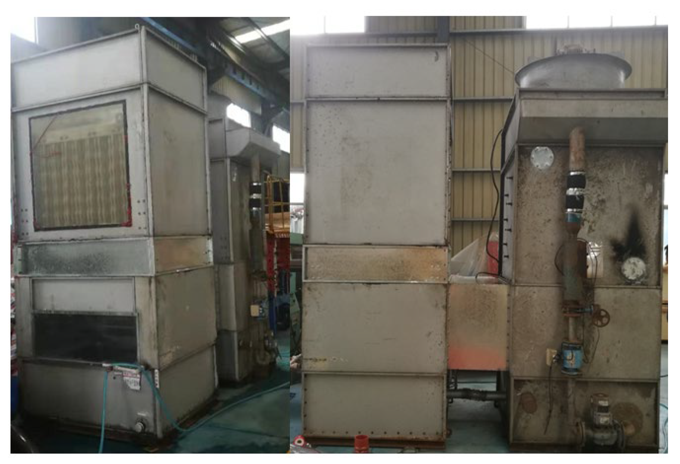
Figure 1, Figure 2, Figure 3 and Figure 4 show the schematic diagram of the CECT before and after the renovation and the photos of the CECT and the experimental system. The experimental test was conducted from 9 to 23 July 2022. With the help of the control system of the shell and tube heat exchanger test platform, the CECT cooling performances under different working conditions were tested. The hot water inlet temperature was controlled by controlling the electric power of the electric heater used in the hot water tank. The spray water volume and cooling air volume were controlled by the frequency converter. The temperature, air humidity, and flow parameters were tested and recorded when the water temperature of the CECT pool was under stable condition. The criterion for the stability of water temperature is that the fluctuation amplitude of the pool temperature is ≤±0.1 °C per minute). From the actual test, the test duration for every operating point needed 40~50 min.

3. Data Reduction

3.1. Cooling Load Test and Heat Balance Analysis

According to the heat transfer rate calculation, the following equation is used to compute the cooling load, where Q is the cooling load; mp is the hot water flow rate; cp is the specific heat of water; Tpi and Tpo are the temperature of inlet and outlet water.
Q = m p c p ( T p i T p o )
In order to test the accuracy of heat dissipation of the CECT, the following equations are used to analyze the heat balance:
Q = Q a + Q l
Q a = m a ( i a o i a i )
Q l = m l c l ( T l i T l o )
where Q′ is the absorbed heat of the air outside the tube and the absorbed heat of the spray water; Qa and Ql are the absorbed heat of the cooling air and the absorbed heat of the spray water; ma and ml are the mass flow rate of the cooling air and the spray water; iai and iao are the air enthalpy at the inlet and the outlet of the CECT; cl is the specific heat of the spray water; and Tli and Tlo are the inlet and the outlet temperature of the spray water.
Generally, when the difference between the heat calculated by using Equations (1) and (2) is within 10%, then it indicates that the experiment has reached the heat balance.

3.2. Overall Heat Transfer Coefficients

The overall heat transfer coefficients of the heat transfer process from the fluid inside the tube to the water film outside the tube can be computed as follows. The average temperature of the water film outside the tube adopts the pool temperature, where Kpw is the overall heat transfer coefficients between the fluid inside the tube and the water film outside the tube; Δtm is the log mean temperature difference (LMTD); Ao is the heat transfer area outside the tubes; and Tw is the average temperature of the water film outside the tube.
K p w = 1000 Q A o Δ t m
Δ t m = T p i T p o ln ( T p i T w T p o T w )

3.3. Pressure Drop of Hot Water

The pressure drop of cooling water for the CECT is calculated by Equation (7), where Δpw is the pressure drop of hot water and ppi and ppo are the inlet and outlet pressure of heat transfer coil.
Δ P w = P w o P w i

3.4. Pressure Drop of Air

The pressure drop of air is determined by Equation (8), where Δpf is the pressure drop of hot air, pfi and pfo are the inlet and outlet pressure of the CECT. Since the inlet pressure can be considered as the local atmospheric pressure, the total pressure drop on the air can be approximately considered as the static pressure at the outlet of the fan.
Δ P f = P f o P f i

3.5. Cooling Tower Performance Evaluation and Cooling Load Modification

There are many evaluation methods for CECTs, although there is no authoritative evaluation standard so far. Commonly used evaluation methods include the cooling amplitude height method, cooling efficiency method, cooling water temperature comparison method, cooling water quantity comparison method, cooling number and ventilation volume comparison evaluation method, etc. [29]. At present, there is no unified CECT performance evaluation standard and many experimental conditions during field cooling performance tests are not controllable. Considering that this experiment mainly investigates the heat transfer performance difference between vertical and horizontal CECT, the experimental test and correction method of cooling load and relative cooling load are adopted for the evaluation [30,31]. This evaluation method takes into account the environmental wet bulb temperature correction and the cooling fluid temperature correction, which are more suitable for the non-packing CECT. The cooling load correction is shown in Equation (9), where Qs and Qb are the measured cooling load and the nominal cooling load; Øτ and Øt are the wet bulb temperature correction coefficient and the cooling fluid temperature correction coefficient, shown in Equations (10) and (11). In the equations, ΔtA is the measured temperature difference between the inlet and outlet of cooling fluid in the tube, which is converted under nominal working conditions. It can be obtained by checking the CECT temperature difference and the wet bulb temperature curve. Additionally, Δtd is the temperature difference between the inlet and outlet of cooling fluid r on the tube side under nominal working condition; ΔTd is the temperature difference between the cooling fluid and wet bulb temperature of the tube side under nominal working condition; ΔTs is the measured temperature difference between the cooling fluid and wet bulb temperature of the tube side under test conditions; and td1, td2, t1, and t2 are the inlet and outlet temperatures of the cooling fluid under the nominal working condition and test condition.
Q b = Q s × τ × t
τ = Δ t d Δ t A
t = Δ T d Δ T s = t d 1 + t d 2 2 t d s t 1 + t 2 2 t s

4. Results and Discussion

Figure 5 shows the comparison between heat dissipation of circulating water in the tube and heat absorption of “air outside the tube + spray water”. It can be seen that the relative errors are within ±10%, mostly within ±5%.
Table 2 gives the comparison between the vertical CECT cooling-load tested value and its conversion to the nominal working-condition under seven different working conditions. The comparison with the nominal working-condition cooling load of the benchmark CECT (the original 3D tube horizontal arrangement CECT) is also shown. The benchmark CECT is a countercurrent 3D horizontal-tube CECT with packing. Its nominal working-condition cooling load is 102 kW. The cooling load of the packed countercurrent CECT is about 1.2 times that of the unpacked countercurrent CECT, according to the performance of the unpacked tower [19,24]. Thus, the cooling load of the benchmark CECT is modified to 85kW under the nominal working condition.
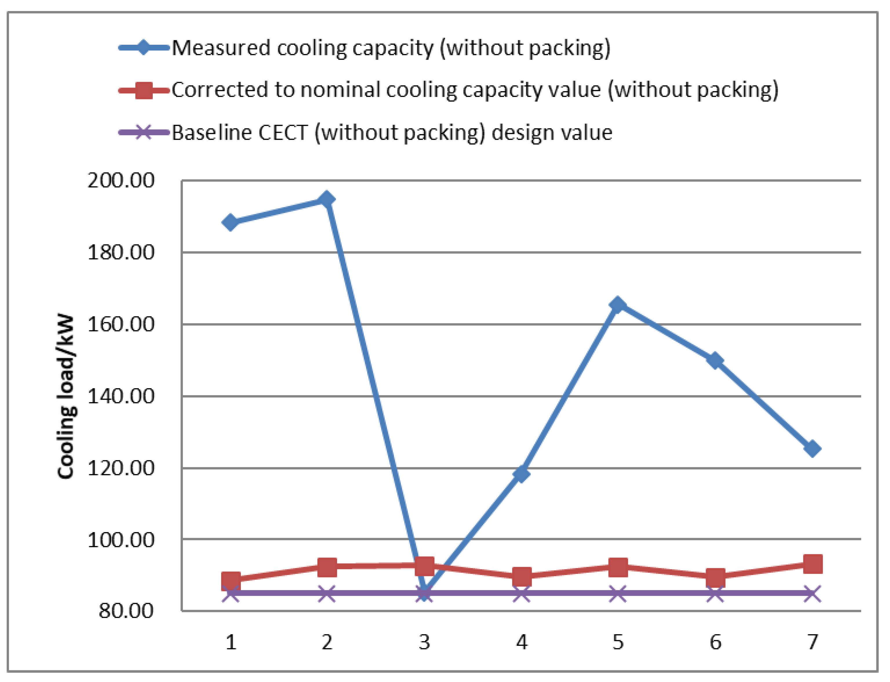
It can be seen from Table 2 and Figure 6 that the measured cooling load of the vertical CECT fluctuates greatly, especially under working condition 3. This phenomenon is due to the influence of the temperature difference between the cooling water and the wet bulb, and the temperature difference between the inlet and outlet cooling water. The temperature difference between the average circulating cooling water and the ambient wet bulb temperature is only 7.95 °C, and the temperature difference between the inlet and outlet temperature of the circulating cooling water is only 2.3 °C for working condition 3. Therefore, the cooling load of the vertical CECT before the correction has a sharp decline compared with other working conditions. The cooling load of the vertical cooling tower for working condition 3 is not very different from the other working conditions after the correction and is even higher than that for working condition 4. This indicates that the cooling water temperature inside the tube and the ambient wet bulb temperature have a significant influence on the cooling load of the cooling tower. After conversion to nominal working conditions, the cooling performance for the vertical 3D deformation-tube CECT is increased by 4.1%~9.6% with an average increase of 7.31% compared with that of the benchmark CECT. Considering that the horizontal and vertical arrangements of tube bundles have little influence on the convective heat transfer inside the tube, it can be assumed that the improvement of the cooling load is mainly caused by the difference in the heat transfer coefficient outside the tube bundle. Perhaps the augmenting mechanism is that the vertical falling-film evaporation effect and the concurrent gas–liquid interface unsaturated evaporation effect of the vertical CECT significantly promote the heat and mass transfer process between the air and water film outside the tube bundle. Thus, the cooling load is enhanced.
h w = 1 1 k p w 1 h f δ d λ d
To further explore the difference between the vertical and horizontal falling-film evaporation outside the tube bundle, the falling-film evaporation heat transfer coefficients of these two different CECT layouts are calculated by using Equation (12). The difference in the tube-side heat transfer coefficient and tube-wall thermal resistance is neglected. The heat transfer coefficient hf in the tube was calculated by the correlation reported in reference [29], where hf and hw are the convective heat transfer coefficients inside the tube and the convective heat transfer coefficient of the water film outside the tube, respectively; and λd and δd are the tube-wall thermal conductivity and tube-wall thickness, respectively. The fouling resistance is neglected.
Figure 7 shows the comparison of the convective heat transfer coefficient of the water film outside the tube bundle of the vertical CECT and of the horizontal CECT under different working conditions. It can be found that under the experimental working conditions, the convective heat transfer coefficient of the water film outside the tube bundle of the vertical CECT is 5.87~12.95% higher than that of the horizontal CECT. The possible reasons for enhanced heat transfer performance of the vertical CECT are as follows. Firstly, the air flow outside the tube bundle is concurrent with the water film, which is conducive to reducing the thickness of the water film and accelerating the flow of the water film. Secondly, the vertical 3D deformation tube is a double-sided wet tube. The special spiral structure is beneficial to the uniform distribution of the water film. In addition, when the water flows through the surface of the 3D deformation-tube bundle, it forms a vortex resulting in circulation and mixing, which enhances the disturbance of the gas–liquid surface. Thirdly, the water film outside the tube bundle of the horizontal CECT is a discontinuous falling-film evaporation process, and it is difficult for the water film to cover the tube surface evenly. Moreover, unusually the settling distance of the water film of the horizontal CECT is too short. The flow state of the water film is usually under laminar or transition flow, resulting in a low heat transfer coefficient for the falling film outside the tube. While a uniform thin layer of water film is formed outside the vertical CECT tube bundle, and the film is continuously falling vertically down along the longitudinal direction of the tube, it thus enhances the turbulence intensity of the water film. Owing to the limitation of the experimental conditions, this experiment cannot detect and quantify the water-film flow state outside the vertical tube bundle.
Figure 8 shows the variation trend of heat flux in the vertical CECT with ambient wet bulb temperature under the same circulating water flow rate, the same spray density, and a similar inlet water temperature (38.5~40.6 °C). It can be seen that with the increase in the wet bulb temperature, the heat flux shows a downward trend. When the wet bulb temperature increased from 22.8 to 27.9 °C, the heat flux decreased from 4.98 to 3.22 kW/m2, a decrease of about 35%. In other words, within this range of wet bulb temperature, the heat flux is reduced by about 7% for every 1 °C increase in the wet bulb temperature. The influence of ambient wet bulb temperature on heat flux is mainly through influencing the temperature of the water film outside the tube. The ambient wet bulb temperature affects the heat transfer temperature difference between the water film and the cooling fluid inside the tube, thus affecting the heat flux. An increase in the wet bulb temperature raises the average water film temperature and decreases the heat flux. Thus, it is easy to understand why the lower the wet bulb temperature (or the drier air), the higher the cooling load of the CECT for the same dry bulb temperature. Under the same cooling load, the relatively dry air can also reduce the cooling air volume and thus reduce the power consumption of the fan.
The overall heat transfer coefficients Kpw (the heat transfer coefficient from the fluid inside the tube to the water film outside the tube) for the horizontal countercurrent CECT (without packing) of circular tube, elliptical tube, and 3D deformation tube are simulated and calculated under several working conditions [32,33]. The results are compared with the tested vertical 3D deformation-tube CECT (without packing). The tested and simulated working conditions are shown in Table 3, and the comparison results are shown in Figure 9.
As can be seen from Figure 9, the variation trend of the tested Kpw value for the vertical CECT is basically consistent with the Kpw calculated value for the other three horizontal CECTs. The overall heat transfer coefficients for the vertical CECT are 35.06%, 18.97%, and 9.45% higher than that for the other three horizontal-arrangement CECT, respectively. This is mainly because the convection heat transfer performance of the fluid inside and outside the irregularly shaped tube is improved compared with that of the circular tube. Moreover, the fluid disturbance of the 3D deformation tube is more obvious, so the performance improvement is the most significant. The overall heat transfer coefficients of the vertical 3D deformation-tube CECT is higher than that of the horizontal 3D deformation-tube CECT. The main reason is that after changing the tube bundle from the horizontal to the vertical arrangement, the wrapping condition of the water film outside the tube is further improved. The heat transfer coefficient of the water-film side outside the tube is increased, leading to a significant improvement in the overall heat transfer coefficients. The measured results only show the comparison of the overall heat transfer coefficient between the vertical arrangement and the horizontal arrangement of the CECT under the same heat exchanger core structure. The influence of optimizing the vertical tube height and space on the overall heat transfer coefficient of CECT needs further study.

5. Conclusions

To overcome the shortcomings of the horizontal-tube CECT, a novel vertical 3D deformation-tube CECT was proposed and developed. The cooling performance of the novel CECT was investigated and compared to the previous traditional horizontal CECT by an experimental method. The findings follow:
(1)
In the range of the test conditions, the cooling load of the novel CECT increases by 4.1~9.6% with an average increase of 7.31% compared to the previous traditional CECT. Additionally, the convective heat transfer coefficient of the water film outside the tube was increased by 5.87~12.95%.
(2)
Compared to the circular, elliptical, and 3D deformation-tube horizontal CECT, the overall heat transfer coefficients of the novel vertical CECT was improved by 35.06%, 18.97%, and 9.45%, respectively.
(3)
The heat flux of the vertical CECT decreases by about 7% when the wet bulb temperature increases by 1 °C under the test range of wet bulb temperature, which indicates that the ambient wet bulb temperature has obvious influence on the cooling load.
(4)
The main reasons for the improvement in cooling performance for the novel vertical CECT may be that the vertical falling-film evaporation effect and concurrent gas–liquid interface unsaturated evaporation effect of the vertical CECT significantly promote the heat and mass transfer process between the air and water film outside the tube bundle, thus augmenting the cooling load.

Author Contributions

Conceptualization, D.Z.; methodology, A.T.; validation, E.C.; formal analysis, A.T., X.M. and X.Z.; investigation, S.L. and X.M.; data curation, X.M., E.C. and X.Z.; writing—original draft preparation, A.T.; writing—review and editing, S.L.; visualization, E.C.; project administration, X.Z. and D.Z.; funding acquisition, S.L. All authors have read and agreed to the published version of the manuscript.

Funding

This research was funded by the Science and Technology Commissioner of Guangdong Province (No. GDKTP2021047200); the Special Cooperation Program of Jilin Province and Chinese Academy of Sciences, (No. 2022SYHZ0027); and the Science and Technology Innovation Project of Foshan National High-tech Zone (No. 2020197000618).

Data Availability Statement

The data presented in this study are available upon reasonable request from the corresponding author.

Conflicts of Interest

The authors declare no conflict of interest.

References

  1. Chaurasiya, V.; Chaudhary, R.K.; Awad, M.M.; Singh, J. A numerical study of a moving boundary problem with variable thermal conductivity and temperature-dependent moving PCM under periodic boundary condition. Eur. Phys. J. Plus 2022, 137, 714. [Google Scholar] [CrossRef]
  2. Chaurasiya, V.; Upadhyay, S.; Rai, K.N.; Singh, J. A new look in heat balance integral method to a two-dimensional Stefan problem with convection. Numer. Heat Transf. Part A Appl. 2022, 82, 529–542. [Google Scholar] [CrossRef]
  3. Chaurasiya, V.; Singh, J. An analytical study of coupled heat and mass transfer freeze-drying with convection in a porous half body: A moving boundary problem. J. Energy Storage 2022, 55, 105394. [Google Scholar] [CrossRef]
  4. Parker, R.O.; Treybal, R.E. The heat mass transfer characteristics of evaporative coolers. AIChE Chem. Eng. Prog. Symp. Ser. 1961, 57, 138–149. [Google Scholar]
  5. Mizushima, T.; Ito, R.; Miyashita, H. Experimental study of evaporative cooler. Int. Chem. Eng. 1967, 7, 727–732. [Google Scholar]
  6. Hasan, A.; Sirén, K. Performance investigation of plain and finned tube evaporatively cooled heat exchangers. Appl. Therm. Eng. 2003, 23, 325–340. [Google Scholar] [CrossRef] [Green Version]
  7. Hasan, A.; Sirén, K. Performance investigation of plain circular and oval tube evaporatively cooled heat exchangers. Appl. Therm. Eng. 2004, 24, 777–790. [Google Scholar] [CrossRef]
  8. Chen, L.; Jiang, B.; Jiang, M.; Feng, Z.; Yang, B.; Liu, Z. Flow pattern criterion and characteristic length of water film outside horizontal tubes. CIESC J. 2010, 61, 15–19. [Google Scholar]
  9. Gao, M.; Zhang, L.; Yang, M.; Li, Z.; Huang, C.; Huang, J.; Su, Y.; Fan, Z. Experimental study on heat transfer performance outside the tube banks for evaporative cooling. J. Eng. Thermophys. 2008, 4, 640–642. [Google Scholar]
  10. He, L.; Ouyang, X.; Zhang, L.; Kong, Q.; Huang, C. Experiment on Resistance of Paralle1-flow and Counter-flow in Closed Cooling Tower. J. Refrig. 2010, 5, 48–52. [Google Scholar]
  11. Harby, K.; Gebaly, D.R.; Koura, N.S.; Hassan, M.S. Performance improvement of vapor compression cooling systems using evaporative condenser: An overview. Renew. Sustain. Energy Rev. 2016, 58, 347–360. [Google Scholar] [CrossRef]
  12. Zhang, L.-X.; Zhang, C.; Liu, J.-N.; Lin, Z.-H.; Ye, J.; Gao, M.; Shen, Y. Nominal condensing capacity and performance evaluation of evaporative condenser. Appl. Therm. Eng. 2016, 107, 79–85. [Google Scholar] [CrossRef]
  13. Fiorentino, M.; Starace, G. Experimental investigations on evaporative condensers performance. Energy Procedia 2017, 140, 458–466. [Google Scholar] [CrossRef]
  14. Xie, X.; He, C.; Zhang, B.; Chen, Q. Counter-Current Gas-Liquid Film Cross-Flow for the Staggered Tube Bundles in Closed Wet Cooling Towers. Chem. Eng. Trans. 2018, 70, 397–402. [Google Scholar]
  15. Bai, Y.; Zhou, Y.; Zhang, X. Analysis of running performance in winter of closed cooling tower. Build. Energy Environ. 2020, 4, 181–186. [Google Scholar]
  16. du Plessis, J.; Owen, M. A validated discretized thermal model for application in bare tube evaporative coolers and condensers. Appl. Therm. Eng. 2020, 175, 115407. [Google Scholar] [CrossRef]
  17. Gong, L.; Zhao, D.; Guo, Y.; Chen, K.; Shen, S. The coupling process of steam condensation and falling film evaporation with non-condensable gas. Int. J. Therm. Sci. 2022, 172, 107201. [Google Scholar] [CrossRef]
  18. Shan, S.; Tan, H. Study on heat and mass transfer characteristics outside flat tube for evaporative condensers. CIESC J. 2019, 70, 69–78. [Google Scholar]
  19. Zheng, W.-Y.; Zhu, D.-S.; Song, J.; Zeng, L.-D.; Zhou, H.-J. Experimental and computational analysis of thermal performance of the oval tube closed wet cooling tower. Appl. Therm. Eng. 2012, 35, 233–239. [Google Scholar] [CrossRef]
  20. Yin, Y.; Zhu, D.; Sun, J.; Li, X.; Tu, A. Experimental investigation of evaporative condensed refrigerating system by variation of heat transfer tube types. Procedia Eng. 2017, 205, 175–182. [Google Scholar] [CrossRef]
  21. Liu, D.; Zhou, Y.; Li, M.; Sha, Z. Simulation of the cooling tower packing’s thermal performance in closed type cooling tower. Build. Energy Environ. 2009, 4, 14–17. [Google Scholar]
  22. Zhou, X.; Deng, K.; Jiang, L. Research on performance of evaporative exchanger with combination use of coil and packing layer. Refrig. Air-Cond. 2010, 4, 88–92. [Google Scholar]
  23. Xie, W. Experimental Research on Heat Transfer Performance of Closed Cooling Tower with Packing Material. Master’s Thesis, Donghua University, Shanghai, China, 2013. [Google Scholar]
  24. Jian, Q.; Dai, C.; Ren, Q.; Zhang, Y. Analysis on flow field and heat transfer of corrugated filler used in evaporative condenser. J. Refrig. 2014, 3, 90–95. [Google Scholar]
  25. Ding, X. Theoretical Analysis and Experimental Verification on Cooling Performance of Closed Cooling Tower with Packing. Master’s Thesis, Donghua University, Shanghai, China, 2015. [Google Scholar]
  26. Wei, J.; Liu, J.; Xu, X.; Ruan, J.; Li, G. Experimental and computational investigation of the thermal performance of a vertical tube evaporative condenser. Appl. Therm. Eng. 2019, 160, 114100. [Google Scholar] [CrossRef]
  27. Du, L.; Sun, H.; Zhang, J.; Shi, X. Experimental study on heat transfer characteristics of cooling falling film outside a vertical tube in open rack vaporizer. Appl. Therm. Eng. 2020, 172, 115187. [Google Scholar]
  28. Shen, Y.; Shi, C.; Zhang, L.; Bu, S.; Xu, W.; Zhang, Z.; Zhu, B.; Xu, C.; Liu, X. Falling film evaporation in a vertical tube with a new type of liquid distributor designed using the brachistochrone principle. Vacuum 2021, 187, 110023. [Google Scholar] [CrossRef]
  29. Bai, H.; Ouyang, X.; Zhao, J.; Li, H. Experiment and performance evaluation of a cross-flow closed cooling tower. J. Eng. Therm. Energy Power 2020, 4, 181–186. [Google Scholar]
  30. JB/T 11530-2013; Closed Cooling Towers for Refrigeration. Ministry of Industry and Information Technology of the People’s Republic of China: Beijing, China, 2013.
  31. GB/T 7190.3-2019; Mechanical Ventilation Cooling Tower—Part 3: Closed Cooling Tower. State Administration for Market Regulation, China National Standardization Administration: Beijing, China, 2019.
  32. Zheng, W. Experimental Investigation and Numerical Simulation of The Heat and Mass Transfer in Evaporative Cooler. Ph.D. Thesis, East China University of Science and Technology, Shanghai, China, 2013. [Google Scholar]
  33. Zhou, X.; Tu, A.; Zhu, D.; Liang, L. Optimization of industrial evaporative cooler operation with energy and water Saving. J. Refrig. 2008, 6, 36–40. [Google Scholar]
Figure 1. Schematic diagram of the CECT before renovation and photo of the heat exchange coil.
Energies 15 09336 g001
Figure 2. Schematic diagram of the vertical CECT: 1—induced draft fan; 2—heat exchanger coil; 3—electromagnetic flowmeter; 4—electronic fouling remover; 5—circulating spray pump; 6—drift eliminator; 7—spray device.
Energies 15 09336 g002
Figure 3. Schematic diagram of the vertical CECT after renovation.
Energies 15 09336 g003
Figure 4. Experimental system control platform and experimental site.
Energies 15 09336 g004
Figure 5. Comparison of heat balance analysis.
Energies 15 09336 g005
Figure 6. Comparison of cooling loads under different operating conditions.
Energies 15 09336 g006
Figure 7. Comparison of the convective heat transfer coefficient of the water film outside the tube bundle under different operating conditions.
Energies 15 09336 g007
Figure 8. Variation trend of heat flux for the vertical CECT with ambient wet bulb temperature.
Energies 15 09336 g008
Figure 9. Comparison of the overall heat transfer coefficients Kpw for the vertical CECT with the other three horizontal CECTs.
Energies 15 09336 g009
Table 1. The main experimental instruments used in the experimental system.
ItemInstrument NameTypeMeasuring RangeMeasuring
Accuracy
Hot water inlet temperatureThermocoupleK−80–400 °CA
Hot water outlet temperatureThermocoupleK−80–400 °CA
Hot water flow rateElectromagnetic flow meterLDBZB-50S-M2F00–50 m3/h0.5%
Spray water temperatureThermocoupleK−80–400 °CA
Spray water flow rateElectromagnetic flow meterLDBZB-50S-M2F00–30m3/h0.5%
Temperature and humidity of air outletHygrometerXM-AR8475~95%RH
−10~80 °C
±3%RH
±0.5 °C
Temperature and humidity of air inletHygrometerXM-AR8475~95%RH
−10~80 °C
±3%RH
±0.5 °C
Air velocityAnemometerTesto 4170.3~20 m/s±(0.1 m/s + 1.5% Measured value)
Atmospheric pressureBarometerYM3800~1064 hPa±2 hPa
Table 2. Comparison between the vertical CECT cooling-load tested value and its conversion to the nominal working-condition under different working conditions.
ItemHot Water Flow VolumeInlet TemperatureOutlet TemperatureDry Bulb TemperatureWet Bulb TemperatureMeasured Cooling LoadTemperature Difference after Wet Bulb CorrectionCooling Load after Wet Bulb CorrectionNominal Operating Cooling LoadDesign Reference Value (without Packing)Ratio to Horizontal Cooling Load
t/h°C°C°C°CkW°CkWkWkW
12843.237.427.724.7188.296156.9188.4885104.10%
23043.237.627.824.8194.795.9165.0792.3985108.70%
33232.229.926.623.185.345.774.8692.8085109.17%
43035.331.926.823.1118.265.75102.8489.6885105.51%
53439.635.426.923.2165.576.4129.3592.3985108.70%
6344036.231.525.4149.805.65132.5789.5785105.38%
73039.335.733.727.3125.224.8130.4493.1785109.61%
Table 3. Comparison of tested value and calculated value for the overall heat transfer coefficients Kpw under several test conditions.
ItemHot Water Flow VolumeAir Flow VolumeInlet TemperatureDry Bulb TemperatureWet Bulb Temperature
m3/hkg/s°C°C°C
1277.743.227.824.8
2307.839.626.923.2
3357.64029.325.4
4407.0639.331.227.3
5456.2440.634.427.4
Publisher’s Note: MDPI stays neutral with regard to jurisdictional claims in published maps and institutional affiliations.