Abstract
Recently, ammonia is emerging as a potential source of energy in power generation and industrial sectors. One of the main concerns with ammonia combustion is the large amount of NO emission. Air staging is a conventional method of reducing NO emission which is similar to the Rich-Burn, Quick-Mix, Lean-Burn (RQL) concept. In air-staged combustion, a major reduction of NO emission is based on the near zero NO emission at fuel-rich combustion of NH3/Air mixture. A secondary air stream is injected for the oxidation of unburned hydrogen and NHx. On the other hand, in fuel-staged combustion, NO emission is reduced by splitting NH3 injection, which promotes the thermal DeNOx process. In this study, NOx emission characteristics of air-staged and fuel-staged combustion of partially cracked ammonia mixture are numerically investigated. First, the combustion system is modeled by a chemical reactor network of a perfectly stirred reactor and plug flow reactor with a detailed chemistry mechanism. Then, the effects of ammonia cracking, residence time, and staging scheme on NOx emission are numerically analyzed. Finally, the limitations and optimal conditions of each staging scheme are discussed.
1. Introduction
In response to global climate change, the combustion society should develop a combustion technology for carbon-neutral fuels. Inherent carbon-free fuels, ammonia, and hydrogen are the potential alternatives to conventional hydrocarbon fuels in the power generation and industry sectors [1,2,3,4,5,6]. Based on the economic analysis using a global cost analysis considering production, storage, transportation, and CO2 capture cost of 30 €/tonCO2 [7], it is expected that, in the near future, ammonia will be produced by renewable hydrogen with a comparative price of methane. The major drawbacks of ammonia combustion are low reactivity and a large amount of NO emission compared to conventional hydrocarbon fuels. The maximum laminar flame speed of NH3/air-premixed flame is about 7 cm/s, and the heating value of ammonia is 18.6 MJ/kg. Therefore, increasing the combustion intensity is essential to realize ammonia combustion for practical applications. Fundamental studies on ammonia combustion focused on this issue in various aspects. These include control of flow dynamics, fuel blending, and oxygen enhancement. Most ammonia gas turbine combustors utilize highly swirling flow [8,9,10,11,12,13], which generates large recirculation zones inside the combustor. These recirculation zones promote the reactions of unburned mixtures by transporting heat and radicals and reducing local flow velocity. Enhancing turbulent mixing can increase turbulent flame speed higher than the laminar flame speed and assist in the stabilization of the flame [14,15]. The mixing of ammonia with more reactive fuel, like hydrogen [16,17,18,19,20,21,22,23,24], methane [25,26,27,28,29], or cracking ammonia [13,23], is another way to improve the reactivity of the fuel. In the oxidizer enhancement approach, the oxygen concentration in the oxidizer increases by mixing air with an oxygen-enriched mixture [14,15,30,31,32]. The two-stage combustion can be used to reduce NOx emissions from the combustion of ammonia. Rich-lean two-stage combustion controls local equivalence ratio and temperature by injecting air after the primary combustion zone [33]. The chemical reactions that oxidize unburned hydrogen and NHx are promoted in the secondary combustion zone. It was reported that air staging can achieve about 32 ppmvd (15% O2) of NO in the model gas turbine combustor [9]. However, the activation of NOx reduction strongly depends on both the equivalence ratio and temperature, and the effective reduction is only valid in a very narrow temperature and equivalence range. Therefore, further research is needed to maximize the advantages of the two-stage combustion as well as explore the operating condition required for NOx reduction.
Numerical simulation could provide helpful guidelines for the design and optimization process of a multi-parameter system. Li et al. [34] developed a Chemical Reactor Network (CRN) of NH3/CH4 fueled gas turbine combustor to analyze the effects of fuel blending and Air-Staged (AS) combustion. Their numerical results showed that low NOx and CO emissions can be achieved for NH3/CH4/air mixtures at H/J class gas turbine conditions with AS combustion. Mashruk et al. numerically assessed humidified Rich-Burn, Quick-Mix, Lean-Burn (RQL) combustors with a CRN [35]. In their research, each part of the reaction zone inside the combustor is modeled as a single reactor based on the thermodynamic state and flow residence time obtained from the RANS CFD analysis. The CRN connects each reactor based on the spatial distribution of the reactors. The fuel is 70–30 (vol%) NH3/H2 mixture, and the oxidizer is an air and steam mixture. This model shows that the humidified RQL system can produce flue gas of 99.97% water with NOx emissions of about 100 ppmv. Bioche et al. [13] performed a large eddy simulation of fuel-rich NH3/H2/air combustion in a model gas turbine combustor. This gas turbine combustor is originally designed for the CH4/air mixture. To adjust the flame characteristics of the mixture to that of methane, they added hydrogen in the NH3/air mixture (XH2 = 0.46). According to their simulation results, there were high emissions of unburned hydrogen and NHx, and the combustion efficiency was about 66% under operating conditions. Authors argued that by adopting AS combustion, combustion efficiency could be increased up to 99.5%.
On the other hand, a stabilization method of pure ammonia flame has to be developed to utilize ammonia in the industrial and power generation sectors. Ammonia has poor combustion characteristics, and its flammable range is much narrower than methane. The maximum laminar flame speed of ammonia is about 1/5 of that of methane. Fuel blending is one way to overcome poor combustion characteristics. Blending ammonia with hydrogen reduces the ignition delay time and the auto-ignition temperature [22] and increases laminar flame speed [21]. Moreover, ammonia is a hydrogen carrier [36]. Hydrogen can be directly converted from ammonia with the cracking process. Mei et al. [23] studied laminar flame propagation of partially cracked NH3/air mixtures in a constant-volume combustion vessel. At 40% of cracking, the laminar burning velocity of the partially cracking ammonia/air mixture is 38.1 cm/s which is close to that of the methane/air mixture. Another interesting result is that the NO formation of a partially cracked ammonia/air mixture exhibits non-monotonic dependency on the cracking ratio. The authors concluded that the transition from ammonia chemistry to cracked gas chemistry is the main source of this behavior.
Even though the development of commercial ammonia-fueled gas turbines has been started [37], there is no systematic study on the staging combustion strategy of ammonia and partially cracked ammonia. Moreover, most study on two-stage combustion is biased toward the rich-lean two-stage combustion concept [9,12,33,34,35,38,39]. The objective of this work is a comparison of conventional and novel two-stage combustion strategies, including air-staging (AS) and fuel-staging (FS) for partially cracked ammonia. The numerical simulations are carried out using a CRN specially developed for two-stage combustion. With this model, we evaluate the concentrations of NO, NO2, and N2O at the exhaust of the combustion system over a wide range of residence time and equivalence ratio.
2. Chemical Reactor Network Model
We developed a CRN model of a partially cracked ammonia combustor with the staged injection to analyze the effect of the staged combustion on the emission characteristics of the NH3/H2/N2/air mixture. The CRN model consists of one Perfectly Stirred Reactor (PSR) and one Plug Flow Reactor (PFR). The PSR represents the primary combustion zone, and the PFR presents the secondary combustion zone. The outlet stream of PSR and secondary stream are mixed, and the mixture flows into the PFR. Figure 1 illustrates a schematic diagram of the CRN model used in this study. The simulation code is written in python using Cantera [40], open source software for thermodynamics and reaction kinetics.
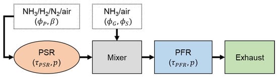
Figure 1.
Schematic diagram of the CRN model of the partially cracked ammonia combustor with staged injection.
The main parameters of the CRN model are the residence time of the PSR reactor (), the residence time of the PFR reactor (), global equivalence ratio (), primary zone equivalence ratio (), staging stream equivalence ratio (), partial cracking ratio (), and operating pressure (p). is the equivalence ratio based on the total injected volumetric flow rate. is the volume fraction of H2 and N2 in the fuel stream. The fuel is a mixture of NH3/H2/N2, and the volume ratio of H2/N2 is fixed at 3:1 to mimic the partially cracked NH3 mixture. The cracking process is an endothermic reaction (2NH3 N2 + 3H2; ΔH0 = 92 kJ/mol−1). However, in order to make the analysis simpler, we did not take into account any heat addition or loss caused by the cracking process. The global reaction of stoichiometric partially cracked ammonia for a given can be written as follows.
The overall ranges of these parameters are summarized in Table 1. For the classification of the staged combustion strategies, we use the following notation. If , then it is the AS combustion. If , we define it as the FS combustion.

Table 1.
The range of the parameters considered in this study.
3. Results and Discussion
3.1. Single PSR Calculation
First, we plot the reactor temperature and NOx concentrations by changing the equivalence ratio and fuel cracking ratio in a single PSR, as shown in Figure 2. All simulation results are computed with the chemistry mechanism of Okafor [28] unless specified otherwise. The peak temperature of the NH3/H2/N2/air mixture is located at a slightly fuel-rich condition. By increasing the portion of cracked ammonia, the peak temperature increases. The maximum temperature of 100% cracked mixture ( = 1) is about 2250 K. On the other hand, the peak of NO is located slightly in fuel-lean condition. Except for = 1, the peak NO concentration increases with increasing H2/N2 mole fraction. Since the main source of NO is fuel-bonded nitrogen, the NO formation mechanism of = 1 and that of others are significantly different, and small amounts of NH3 inside the fuel stream could yield large amounts of NOx in the NH3/H2/N2/air mixture. Most of the NO in the NH3/H2/air mixture is produced by the HNO pathway [23,24,34], and this pathway is limited by the availability of oxygen. Moreover, NO concentration is very sensitive to temperature. For example, at = 0.6, the temperature range for 0 is from 1491 to 1596 K. However, the NO concentration distributes from 474 to 2589 ppmv at that condition. Another important characteristic of the NO concentration profile is the strong non-linearity at the fuel-rich condition. The NO concentration stiffly drops at = 0.95 and reaches about 50 ppmv at = 1.55 for = 0. This preliminary computational result suggests that if the primary combustion zone is in a fuel-rich condition, near zero NO, NO2 and N2O are achievable [9,12]. Thus, the complete combustion of partially oxidized NH3 with a secondary air stream is the key to low NOx combustion. On the other hand, if the primary combustion zone is in fuel-lean condition, then the secondary stream must reduce concentrations of NO, NO2, and N2O below acceptable values. To achieve this, the secondary stream is carefully controlled to activate ammonia-based Selective Non-Catalytic Reduction (SNCR) [41], also known as the thermal DeNOx [42]. It should be noted that the original thermal DeNOx process is developed for NOx reduction in a hydrocarbon fuel combustion. Therefore, past studies on thermal DeNOx were mainly focused on NO reduction. However, the reduction of NO2 and N2O is also an important issue in ammonia combustion. We will investigate the effect of staged combustion on the emission characteristics of NO, NO2, and N2O in the following section.
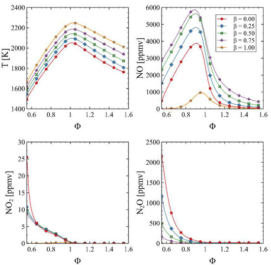
Figure 2.
Effect of equivalence ratio on temperature and NO, NO2, and N2O mole fractions in a PSR ( = 0.1 s).
3.2. Effect of Staged Combustion
CRN model illustrated in Figure 1 is used to demonstrate the effect of staged combustion. Figure 3 shows the effect of in AS with pure ammonia (). It is shown that for the three values, the minimum level of NO is located at the upper left corner of the contour maps. The primary combustion zone needs a relatively long time to minimize the concentration of NO. On the other hand, the secondary combustion zone has to provide efficient mixing of secondary air and product of the primary combustion zone in a short time to delay the thermodynamic state of the mixture’s progress to the chemical equilibrium. This large and small is also the condition for a local minimum of NO2. On the other hand, N2O decreases by increasing . This indicates the trade-off between NO and N2O at the fuel-lean condition, as shown in Figure 2.
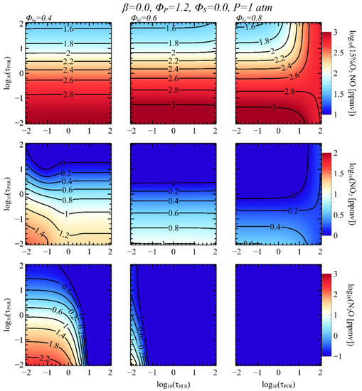
Figure 3.
Contour maps of NOx emission in AS CRN. Each column represents computational results with different .
Figure 4 shows the effect of in FS CRN. Due to the low reactivity of the mixture, the flame is extinguished when the residence time of the primary combustion zone is short (). If is long enough to stabilize the combustion, the determines the overall characteristics of the exhaust emissions. It is identified that the abrupt increase in NO is related to the combustion of the secondary stream NH3/air mixture. The more NH3 is injected, the longer residence time is required to oxidize NH3. For instance, the = 100 s is not enough to secondary injected NH3/air mixture to react in case of = 0.9. Relatively low NO and N2O with a certain level of NO2 are found at the upper left of the contour. However, a large amount of unburned NH3 is also found in this region. The trade-off between NO and N2O is the primary issue with FS combustion at high global equivalence ratios. In Figure 4, the contours of NO and N2O have the same interface where the stiff variations of species concentration with opposite directions are observed for = 0.7 and 0.8. It shows the trade-off between NO and N2O and the limitations of FS combustion with high-temperature exhaust gas. Figure 5 shows the effect of and on the emission map of two-stage combustion. Three operating conditions with fixed are simulated. On the left side of the figure, the computational results of = 0.6/ = 0 are shown. It is AS combustion with a lean primary combustion zone. The figure shows a very high level of NO concentration for all stable combustion, but the NO2 and N2O levels are very low if is larger than 1 s. There is no effective regime for NOx reduction. Thus, AS combustion is not an effective way of NOx reduction when is fuel-lean. On the other hand, the other two cases simulate FS combustion. It is clearly shown that a small amount of ammonia addition in the secondary stream yields a remarkable reduction of NO. Moreover, for = 0.6/ = 0.1, there exists a clean combustion regime where NO, NO2, and N2O levels are below 10 ppmv. It seems that should be longer than a certain limit to achieve this condition, and this critical depends on the equivalence ratio of the secondary injected stream. The critical residence time for = 0.6/ = 0.1 and = 0.6/ = 0.2 is about 10 and 100 s, respectively.
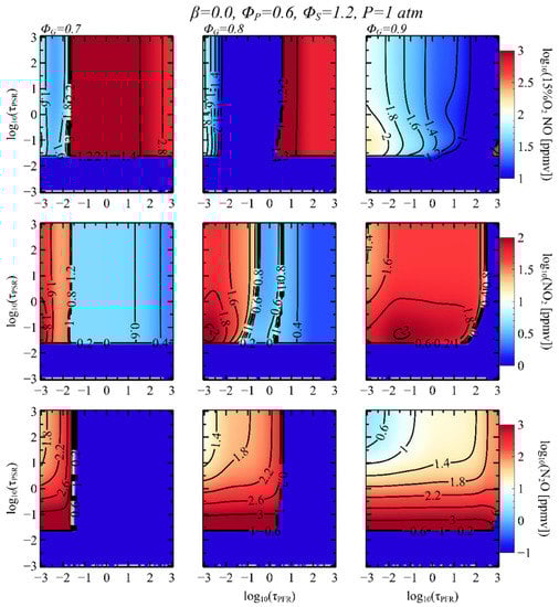
Figure 4.
Contour maps of NOx emission in FS CRN. Each column represents computational results with different .
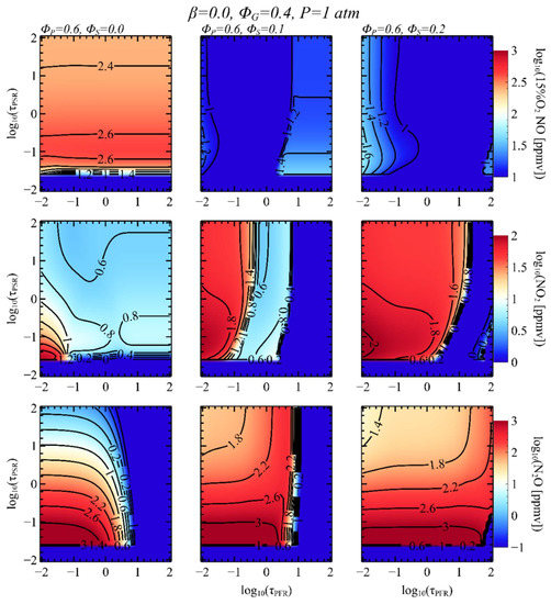
Figure 5.
Contour maps of NOx emission in FS CRN. Each column represents computational results with different and .
In Figure 6, we compare two staged combustion strategies at = 0.45. NOx mole fraction and temperature versus are plotted. For FS combustion, a high level of NH3 is present in the exhaust gas for < 0.6 s. When > 0.6 s, NH3 and N2O converted to the N2 with a small formation of NO. However, AS combustion is not an effective way of NO reduction for = 0.45. The level of NO and NO2 is nearly constant, and only N2O drops from 5 to 0.02 ppmv by increasing . Figure 7 compares two staged combustion strategies at = 0.7. As shown in Figure 4, FS combustion is ineffective for reducing NO in high-temperature exhaust gas. The NO level in the exhaust gas is higher than 1000 ppmv. A long residence time is required to reduce it, and its equilibrium concentration is not at an environmentally acceptable level. On the other hand, the NO level in AS combustion is about 200 ppmv, and levels of NO2 and N2O are lesser than 3 ppmv for < 1 s. However, the NO, NO2, and N2O levels of AS combustion become similar to those values of FS combustion when is about 1000 s. It implies that the two staged combustion strategies yield the same equilibrium condition at these operating conditions.
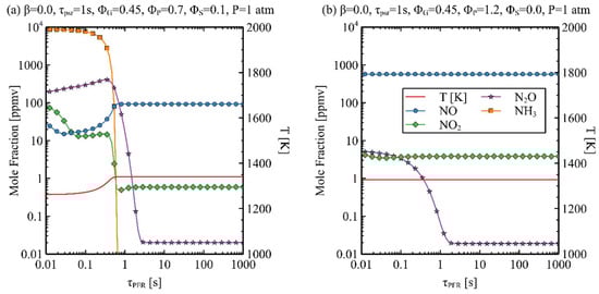
Figure 6.
NOx and temperature versus for = 0.45. (a) FS, (b) AS.
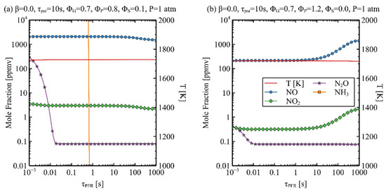
Figure 7.
NOx and temperature versus for = 0.7. (a) FS, (b) AS.
3.3. Effect of Ammonia Cracking Ratio
Next, we investigate the effect of the cracked ammonia ratio. Figure 8 and Figure 9 show the contour maps of NOx emissions for = 0.25, 0.5, and 0.75 in an AS CRN and FS CRN, respectively. Essentially, the same trends are found for both AS and FS cases with respect to the variation of . At fixed and , the level of NO increases with increasing . The cracked gas accelerates chain-branching reactions which produce O and OH radicals [23]. This chemical effect leads to the increase of NO. However, the overall landscapes of the contour maps are not varying significantly with . This means that the staged combustion strategies can be applied to a wide range of cracked ammonia and ammonia mixture without a major modification. Additionally, increasing decreases required for activation of NO reduction in an FS combustion. This result is consistent with the experimental study of rich-lean combustion in NH3/H2-fueled combustors [9].
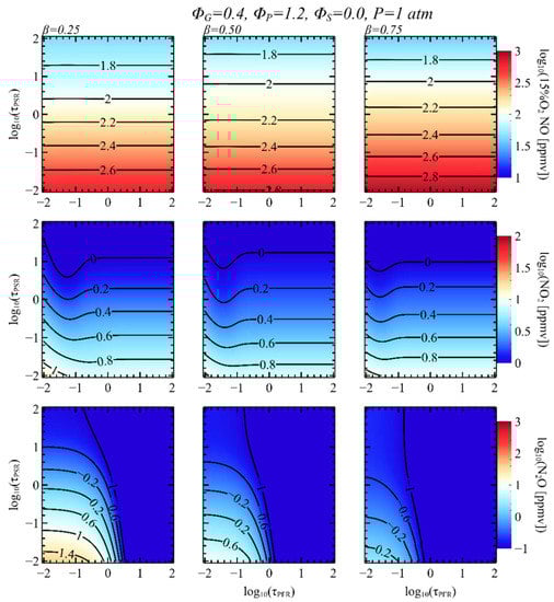
Figure 8.
Contour maps of NOx emission in staged combustion CRN. Each column represents computational results with different .
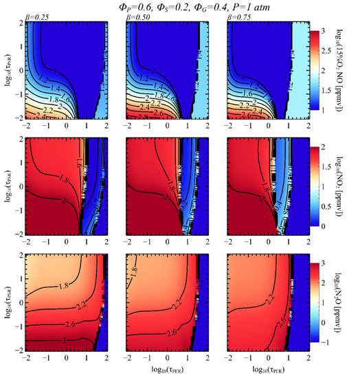
Figure 9.
Contour maps of NOx emission in FS CRN. Each column represents computational results with different .
3.4. Effects of Pressure and Chemistry Mechanism
Finally, we investigated the effects of pressure and chemistry mechanisms on the prediction of temperature and NO mole fraction. Figure 10 and Figure 11 show 15% O2 NO concentration and the corresponding temperature of CRN for two-stage combustion computed with various chemistry mechanisms at 1, 10, and 30 atm. We checked not only NH3 concentration but also NH3, NO2, and N2O for various chemistry mechanisms. However, NO is the only chemical species that show noticeable deviations among the chemistry mechanisms considered here. The differences between mole fractions are lesser than 5 ppm for other species. The calculation condition for AS CRN is = 0.7, = 1.2, = 0, = 100 s, and = 1 s. In terms of 15% O2 NO concentration, each chemistry mechanism predicted different trends and quantities. Okafor’s [28] mechanism predicts the maximum NO level of 16.9 ppm at 1 atm, and it decreases to 7.1 ppm at 30 atm. Otomo’s mechanism [24] shows a nearly constant level of NO. The values of NO concentration at 1, 10, and 30 atm are 19.6, 18.8, and 18.7 ppm. Tian’s mechanism [27] shows an opposite trend with respect to Okafor’s mechanism. The NO concentration increases from 25.8 to 38.1 ppm with increasing pressure. The calculation condition for FS CRN is = 0.4, = 0.7, = 0.1, = 1 s, and = 10 s. The discrepancies between the chemistry mechanisms in AS combustion are mentioned in [35]. In that study, the simulations are conducted with the chemistry mechanisms of Okafor [28], Glarborg [43], Xiao [19], Tian [29], and Otomo [24]. The major source of NO production at the primary combustion is from HNO, but the calculated production rate of NO from the Glaborg mechanism, Otomo mechanism, and Xiao mechanism are all different. This is partly attributed to uncertainties in important species such as HONO, HNO, NH2, OH, N, and H [35]. Compared to the AS CRN results, much more consistent predictions are found for FS CRN. All three mechanisms predict the same non-monotonic behavior with pressure increasing. The differences between predicted NO concentrations are lesser than 10 ppm for this condition. For the temperature prediction, differences between chemistry mechanisms are lesser than 2 K. These results show that there exist uncertainties in high-pressure reaction rate, especially for the reactions involved in AS combustion. However, the computational results also confirm that these two NOx reduction strategies are applicable to a high-pressure environment. At 20 bar, for the activation of NO reduction is 0.001 and 0.3 s for AS combustion and FS combustion, respectively. These are values relevant to the operating conditions of practical gas turbine applications.
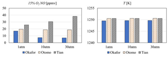
Figure 10.
Effects of reactor pressure and chemical mechanism in AS CRN.
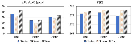
Figure 11.
Effects of reactor pressure and chemical mechanism in FS CRN.
4. Conclusions
In this study, we systematically investigate the combustion of the NH3/H2/N2 mixture using a staged combustion CRN. A wide range of CRN parameters is considered to find the effective regions of NOx reduction for air-staged and fuel-staged combustion. Key findings can be summarized as follows.
- Both air- and fuel-staged combustion strategies can be viable solutions for NO reduction in an ammonia combustion system. However, the optimal operation points of these two-stage combustion strategies are distinctively different. The air-staged combustion can be utilized with a fuel-rich primary combustion zone of long residence time. The residence time of the secondary combustion zone for unburned H2 and NHx should be short enough to prevent the mixture reaches chemical equilibrium. On the contrary, fuel-staged combustion is an effective way of NO reduction for a fuel-lean primary combustion zone. For this strategy, the secondary combustion zone with a long residence time is required to activate the thermal DeNOx process. Moreover, the temperature of the secondary combustion zone should be low enough to prevent an abrupt NO formation.
- Considering the predicted concentrations of NO, N2O, NO2, and NH3 from fuel-staged CRN, fuel-staged combustion could be a promising way of low NOx ammonia combustion. Unrealistically long residence time required for low NOx staging combustion indicates that low reactivity of NH3 could be problematic for some real applications. However, at elevated temperature and pressure, the CRN model shows the reduction of NOx with the residence time of O(1) ms.
- The cracked ammonia ratio essentially does not change the emission characteristics when the cracked ammonia ratio is not close to 1.0. However, the increment of the reactivity with ammonia cracking slightly increases the level of NO and decreases residence time for NH3 oxidation.
- Non-linearity of NO formation in terms of reactor residence time, mixture composition, and staged injection, together with a narrow region of effective NOx reduction, implies that accurate control of flow dynamic is necessary for a low NOx ammonia combustion system.
- The three chemistry mechanisms of Okafor, Otomo, and Tian are used to estimate the uncertainties in simulation results. The differences in temperature, NH3, NO2, and N2O predictions are negligible. However, they show qualitatively and quantitatively different predictions in terms of NO concentration, especially at high-pressure conditions. Although reaction rates in high-pressure simulations lead to large discrepancies in NO predictions, all three mechanisms demonstrate that both air- and fuel-staged combustion strategies are still applicable to high-pressure environments.
Author Contributions
Conceptualization, N.K. and M.L.; methodology, N.K., J.P. (Juwon Park) and J.P. (Jeongje Park); software, N.K.; validation, N.K., M.L., J.P. (Juwon Park) and J.P. (Jeongje Park); formal analysis, N.K., M.L. and T.L.; investigation, N.K., J.P. (Juwon Park) and J.P. (Jeongje Park); resources, M.L.; data curation, N.K.; writing—original draft preparation, N.K.; writing—review and editing, M.L. and T.L.; visualization, N.K.; supervision, M.L.; project administration, M.L.; funding acquisition. All authors have read and agreed to the published version of the manuscript.
Funding
This work was supported by the Korea Institute of Energy Technology Evaluation and Planning (KETEP) and the Ministry of Trade, Industry & Energy (MOTIE) of the Republic of Korea (No. 20202020800200).
Conflicts of Interest
The authors declare no conflict of interest.
References
- Lee, H.; Lee, M.J. Recent Advances in Ammonia Combustion Technology in Thermal Power Generation System for Carbon Emission Reduction. Energies 2021, 14, 5604. [Google Scholar] [CrossRef]
- Xu, X.; Liu, E.; Zhu, N.; Liu, F.; Qian, F.; Xu, X.; Liu, E.; Zhu, N.; Liu, F.; Qian, F. Review of the Current Status of Ammonia-Blended Hydrogen Fuel Engine Development. Energies 2022, 15, 1023. [Google Scholar] [CrossRef]
- Stefanizzi, M.; Capurso, T.; Filomeno, G.; Torresi, M.; Pascazio, G. Recent Combustion Strategies in Gas Turbines for Propulsion and Power Generation toward a Zero-Emissions Future: Fuels, Burners, and Combustion Techniques. Energies 2021, 14, 6694. [Google Scholar] [CrossRef]
- Mounaïm-Rousselle, C.; Bréquigny, P.; Dumand, C.; Houillé, S. Operating Limits for Ammonia Fuel Spark-Ignition Engine. Energies 2021, 14, 4141. [Google Scholar] [CrossRef]
- Imhoff, T.B.; Gkantonas, S.; Mastorakos, E. Analysing the Performance of Ammonia Powertrains in the Marine Environment. Energies 2021, 14, 7447. [Google Scholar] [CrossRef]
- Bonasio, V.; Ravelli, S. Performance Analysis of an Ammonia-Fueled Micro Gas Turbine. Energies 2022, 15, 3874. [Google Scholar] [CrossRef]
- Ghavam, S.; Vahdati, M.; Wilson, I.A.G.; Styring, P. Sustainable Ammonia Production Processes. Front. Energy Res. 2021, 9, 34. [Google Scholar] [CrossRef]
- Hayakawa, A.; Arakawa, Y.; Mimoto, R.; Somarathne, K.D.K.A.; Kudo, T.; Kobayashi, H. Experimental Investigation of Stabilization and Emission Characteristics of Ammonia/Air Premixed Flames in a Swirl Combustor. Int. J. Hydrogen Energy 2017, 42, 14010–14018. [Google Scholar] [CrossRef]
- Pugh, D.; Bowen, P.; Valera-Medina, A.; Giles, A.; Runyon, J.; Marsh, R. Influence of Steam Addition and Elevated Ambient Conditions on NO x Reduction in a Staged Premixed Swirling NH3/H2 Flame. Proc. Combust. Inst. 2019, 37, 5401–5409. [Google Scholar] [CrossRef]
- Wei, X.; Zhang, M.; An, Z.; Wang, J.; Huang, Z.; Tan, H. Large Eddy Simulation on Flame Topologies and the Blow-off Characteristics of Ammonia/Air Flame in a Model Gas Turbine Combustor. Fuel 2021, 298, 120846. [Google Scholar] [CrossRef]
- Valera-Medina, A.; Gutesa, M.; Xiao, H.; Pugh, D.; Giles, A.; Goktepe, B.; Marsh, R.; Bowen, P. Premixed Ammonia/Hydrogen Swirl Combustion under Rich Fuel Conditions for Gas Turbines Operation. Int. J. Hydrogen Energy 2019, 44, 8615–8626. [Google Scholar] [CrossRef]
- Somarathne, K.D.K.A.; Hatakeyama, S.; Hayakawa, A.; Kobayashi, H. Numerical Study of a Low Emission Gas Turbine like Combustor for Turbulent Ammonia/Air Premixed Swirl Flames with a Secondary Air Injection at High Pressure. Int. J. Hydrogen Energy 2017, 42, 27388–27399. [Google Scholar] [CrossRef]
- Bioche, K.; Bricteux, L.; Bertolino, A.; Parente, A.; Blondeau, J. Large Eddy Simulation of Rich Ammonia/Hydrogen/Air Combustion in a Gas Turbine Burner. Int. J. Hydrogen Energy 2021, 46, 39548–39562. [Google Scholar] [CrossRef]
- Wang, S.; Elbaz, A.M.; Wang, Z.; Roberts, W.L. The Effect of Oxygen Content on the Turbulent Flame Speed of Ammonia/Oxygen/Nitrogen Expanding Flames under Elevated Pressures. Combust. Flame 2021, 232, 111521. [Google Scholar] [CrossRef]
- Xia, Y.; Hashimoto, G.; Hadi, K.; Hashimoto, N.; Hayakawa, A.; Kobayashi, H.; Fujita, O. Turbulent Burning Velocity of Ammonia/Oxygen/Nitrogen Premixed Flame in O2-Enriched Air Condition. Fuel 2020, 268, 117383. [Google Scholar] [CrossRef]
- da Rocha, R.C.; Costa, M.; Bai, X.S. Chemical Kinetic Modelling of Ammonia/Hydrogen/Air Ignition, Premixed Flame Propagation and NO Emission. Fuel 2019, 246, 24–33. [Google Scholar] [CrossRef]
- Goldmann, A.; Dinkelacker, F. Approximation of Laminar Flame Characteristics on Premixed Ammonia/Hydrogen/Nitrogen/Air Mixtures at Elevated Temperatures and Pressures. Fuel 2018, 224, 366–378. [Google Scholar] [CrossRef]
- Wang, S.; Wang, Z.; Elbaz, A.M.; Han, X.; He, Y.; Costa, M.; Konnov, A.A.; Roberts, W.L. Experimental Study and Kinetic Analysis of the Laminar Burning Velocity of NH3/Syngas/Air, NH3/CO/Air and NH3/H2/Air Premixed Flames at Elevated Pressures. Combust. Flame 2020, 221, 270–287. [Google Scholar] [CrossRef]
- Xiao, H.; Valera-Medina, A. Chemical Kinetic Mechanism Study on Premixed Combustion of Ammonia/Hydrogen Fuels for Gas Turbine Use. J. Eng. Gas Turbine Power 2017, 139, 81504. [Google Scholar] [CrossRef]
- Vigueras-Zuniga, M.O.; Tejeda-Del-Cueto, M.E.; Vasquez-Santacruz, J.A.; Herrera-May, A.L.; Valera-Medina, A. Numerical Predictions of a Swirl Combustor Using Complex Chemistry Fueled with Ammonia/Hydrogen Blends. Energies 2020, 13, 288. [Google Scholar] [CrossRef]
- Ichikawa, A.; Hayakawa, A.; Kitagawa, Y.; Kunkuma Amila Somarathne, K.D.; Kudo, T.; Kobayashi, H. Laminar Burning Velocity and Markstein Length of Ammonia/Hydrogen/Air Premixed Flames at Elevated Pressures. Int. J. Hydrogen Energy 2015, 40, 9570–9578. [Google Scholar] [CrossRef]
- He, X.; Shu, B.; Nascimento, D.; Moshammer, K.; Costa, M.; Fernandes, R.X. Auto-Ignition Kinetics of Ammonia and Ammonia/Hydrogen Mixtures at Intermediate Temperatures and High Pressures. Combust. Flame 2019, 206, 189–200. [Google Scholar] [CrossRef]
- Mei, B.; Zhang, J.; Shi, X.; Xi, Z.; Li, Y. Enhancement of Ammonia Combustion with Partial Fuel Cracking Strategy: Laminar Flame Propagation and Kinetic Modeling Investigation of NH3/H2/N2/Air Mixtures up to 10 Atm. Combust. Flame 2021, 231, 111472. [Google Scholar] [CrossRef]
- Otomo, J.; Koshi, M.; Mitsumori, T.; Iwasaki, H.; Yamada, K. Chemical Kinetic Modeling of Ammonia Oxidation with Improved Reaction Mechanism for Ammonia/Air and Ammonia/Hydrogen/Air Combustion. Int. J. Hydrogen Energy 2018, 43, 3004–3014. [Google Scholar] [CrossRef]
- Okafor, E.C.; Naito, Y.; Colson, S.; Ichikawa, A.; Kudo, T.; Hayakawa, A.; Kobayashi, H. Experimental and Numerical Study of the Laminar Burning Velocity of CH4–NH3–Air Premixed Flames. Combust. Flame 2018, 187, 185–198. [Google Scholar] [CrossRef]
- Li, R.; Konnov, A.A.; He, G.; Qin, F.; Zhang, D. Chemical Mechanism Development and Reduction for Combustion of NH3/H2/CH4 Mixtures. Fuel 2019, 257, 116059. [Google Scholar] [CrossRef]
- Wang, S.; Wang, Z.; Chen, C.; Elbaz, A.M.; Sun, Z.; Roberts, W.L. Applying Heat Flux Method to Laminar Burning Velocity Measurements of NH3/CH4/Air at Elevated Pressures and Kinetic Modeling Study. Combust. Flame 2022, 236, 111788. [Google Scholar] [CrossRef]
- Okafor, E.C.; Naito, Y.; Colson, S.; Ichikawa, A.; Kudo, T.; Hayakawa, A.; Kobayashi, H. Measurement and Modelling of the Laminar Burning Velocity of Methane-Ammonia-Air Flames at High Pressures Using a Reduced Reaction Mechanism. Combust. Flame 2019, 204, 162–175. [Google Scholar] [CrossRef]
- Tian, Z.; Li, Y.; Zhang, L.; Glarborg, P.; Qi, F. An Experimental and Kinetic Modeling Study of Premixed NH3/CH4/O2/Ar Flames at Low Pressure. Combust. Flame 2009, 156, 1413–1426. [Google Scholar] [CrossRef]
- Wang, D.; Ji, C.; Wang, Z.; Wang, S.; Zhang, T.; Yang, J. Measurement of Oxy-Ammonia Laminar Burning Velocity at Normal and Elevated Temperatures. Fuel 2020, 279, 118425. [Google Scholar] [CrossRef]
- Li, J.; Huang, H.; Kobayashi, N.; He, Z.; Osaka, Y.; Zeng, T. Numerical Study on Effect of Oxygen Content in Combustion Air on Ammonia Combustion. Energy 2015, 93, 2053–2068. [Google Scholar] [CrossRef]
- Shrestha, K.P.; Lhuillier, C.; Barbosa, A.A.; Brequigny, P.; Contino, F.; Mounaïm-Rousselle, C.; Seidel, L.; Mauss, F. An Experimental and Modeling Study of Ammonia with Enriched Oxygen Content and Ammonia/Hydrogen Laminar Flame Speed at Elevated Pressure and Temperature. Proc. Combust. Inst. 2021, 38, 2163–2174. [Google Scholar] [CrossRef]
- Kobayashi, H.; Hayakawa, A.; Somarathne, K.D.K.A.; Okafor, E.C. Science and Technology of Ammonia Combustion. Proc. Combust. Inst. 2019, 37, 109–133. [Google Scholar] [CrossRef]
- Li, S.; Zhang, S.; Zhou, H.; Ren, Z. Analysis of Air-Staged Combustion of NH3/CH4 Mixture with Low NOx Emission at Gas Turbine Conditions in Model Combustors. Fuel 2019, 237, 50–59. [Google Scholar] [CrossRef]
- Mashruk, S.; Xiao, H.; Valera-Medina, A. Rich-Quench-Lean Model Comparison for the Clean Use of Humidified Ammonia/Hydrogen Combustion Systems. Int. J. Hydrogen Energy 2021, 46, 4472–4484. [Google Scholar] [CrossRef]
- Aziz, M.; TriWijayanta, A.; Nandiyanto, A.B.D. Ammonia as Effective Hydrogen Storage: A Review on Production, Storage and Utilization. Energies 2020, 13, 3062. [Google Scholar] [CrossRef]
- Nose, M.; Kawakami, T.; Nakamura, S.; Kuroki, H.; Kataoka, M.; Yuri, M. Development of Hydrogen/Ammonia Firing Gas Turbine for Decarbonized Society. Mitsubishi Heavy Ind. Technol. Rev. 2021, 58, 1. [Google Scholar]
- Okafor, E.C.; Somarathne, K.D.K.A.; Ratthanan, R.; Hayakawa, A.; Kudo, T.; Kurata, O.; Iki, N.; Tsujimura, T.; Furutani, H.; Kobayashi, H. Control of NOx and Other Emissions in Micro Gas Turbine Combustors Fuelled with Mixtures of Methane and Ammonia. Combust. Flame 2020, 211, 406–416. [Google Scholar] [CrossRef]
- Kikuchi, K.; Murai, R.; Hori, T.; Akamatsu, F. Fundamental Study on Ammonia Low-NOx Combustion Using Two-Stage Combustion by Parallel Air Jets. Processes 2021, 10, 23. [Google Scholar] [CrossRef]
- Cantera 2.5.1. Available online: https://cantera.org/ (accessed on 4 October 2022).
- Mussatti, D.C. Epa Air Pollution Control Cost Manual, 6th ed.; US Environmental Protection Agency: Research Triangle Park, NC, USA, 2002.
- Lyon, R.K.; Hardy, J.E. Discovery and Development of the Thermal Denox Process. Ind. Eng. Chem. Fundam. 1986, 25, 19–24. [Google Scholar] [CrossRef]
- Glarborg, P.; Miller, J.A.; Ruscic, B.; Klippenstein, S.J. Modeling Nitrogen Chemistry in Combustion. Prog. Energy Combust. Sci. 2018, 67, 31–68. [Google Scholar] [CrossRef]


Publisher’s Note: MDPI stays neutral with regard to jurisdictional claims in published maps and institutional affiliations. |
© 2022 by the authors. Licensee MDPI, Basel, Switzerland. This article is an open access article distributed under the terms and conditions of the Creative Commons Attribution (CC BY) license (https://creativecommons.org/licenses/by/4.0/).