1. Introduction
Industry 4.0 promotes the integration of smart technologies and production systems. Among these, Additive Manufacturing (AM) plays an essential role in meeting some of the most essential requirements of the fourth industrial revolution [
1]. AM, also known as 3D printing, was first developed in the 1980s. It was initially used as a custom tool for fast prototyping, but now it has developed to cover a wide range of technologies. From small applications to large aerospace and defense industries, additive manufacturing is clearly the key driver for further innovation and development. In this context, many manufacturers are taking steps toward a more advanced manufacturing to keep up with the rapid prototyping in their industry. In this fast development environment, AM allows more convergence between both design and manufacturing by speeding up the design process. It can effectively help manufacturers to address the emerging trends and latest advancements.
Generally speaking, the industrial benefits of AM are broad:
- (i)
low-volume production—AM is considered an ideal cost-effective tool to produce low volume and limitless complex geometrical parts;
- (ii)
design optimization and weight reduction—which are also very beneficial to aircraft and space applications, since they result in considerable fuel savings and lower carbon dioxide emissions;
- (iii)
clean technology—unlike traditional subtractive manufacturing, AM has almost zero waste, which qualifies it to be among other green-energy technologies;
- (iv)
part consolidation—the ability to integrate different components into a single part, which can significantly simplify and reduce the time of assembly or repair processes.
Recently, metal 3D printing has been an important fast-growing aspect of the industry of additive manufacturing. There are three main criteria to measure the value of metal AM against traditional machining: product performance, time saving, and production cost.
When it was first introduced, metal AM was slower and more expensive than conventional existing techniques. As a result, its utilization was limited to applications where the product value outweighed the drawbacks in terms of time and money. Nowadays, metal AM technology can compete with machining in terms of speed and cost. Furthermore, due to its shortcomings, such as high-cost machinery, material waste, and experience requirements, subtractive manufacturing is not considered the best choice for many applications, such as titanium and other hard metals.
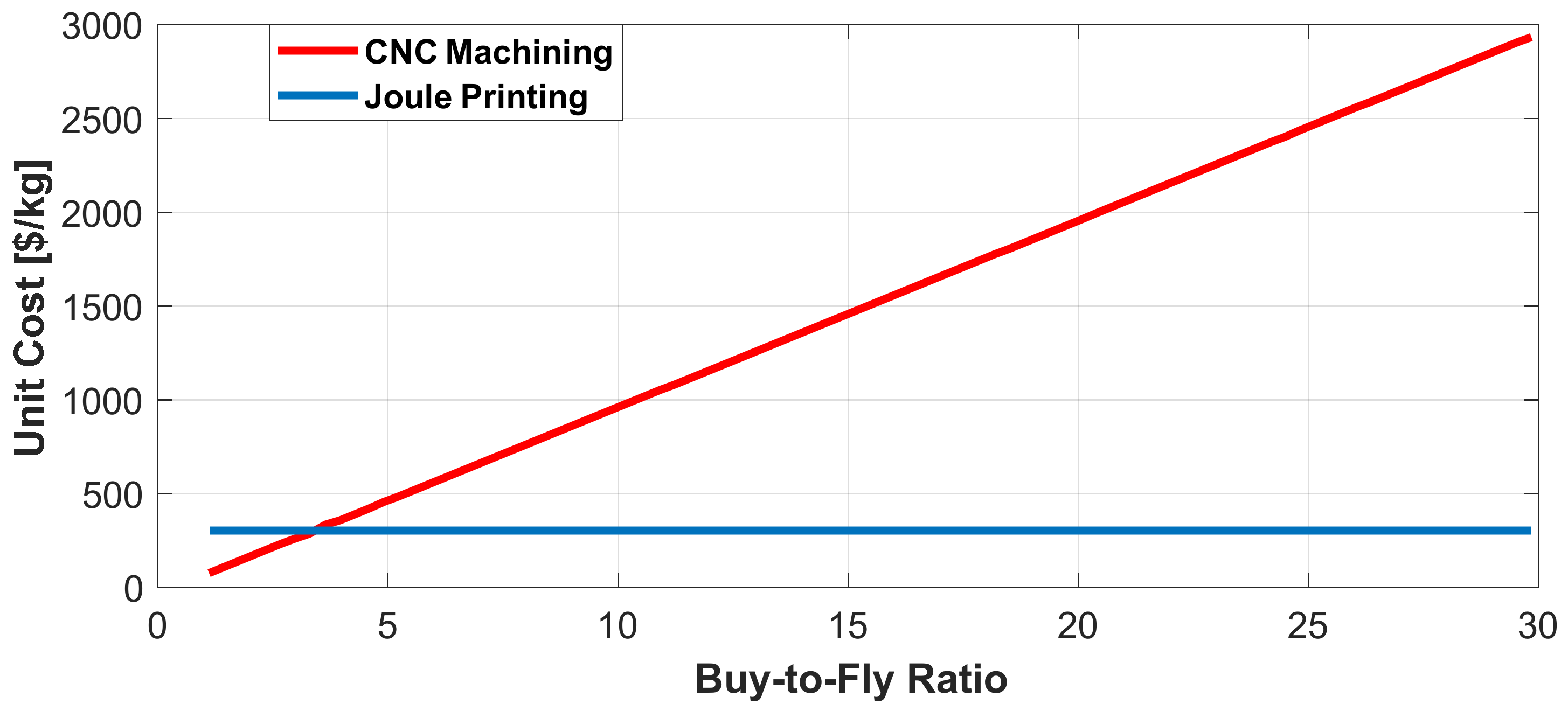
In typical metal manufacturing, a key driver for the production process cost is the buy-to-fly ratio [
2,
3] which is the ratio of the mass of the starting billet of the raw material (buy) to the mass of the finished part (fly), as illustrated in
Figure 1. The amount of material waste during production depends mainly on this ratio. For example, a buy-to-fly value of 10-to-1 means that only 10% of the raw material remains in the machined part. In a practical approach, with an average of 11:1 ratio in the aerospace industry, a large manufacturer may consume 60 t of raw titanium daily to produce only 5.4 t of finished parts.
Another important criterion in the compromise between machining and AM is energy efficiency. For instance, in conventional metal manufacturing, the required energy to machine 1 kg of titanium exceeds 40 kWh. However, AM needs only less than 1 kWh for the same weight [
2,
3]. Furthermore, this remarkable difference between the required energy is then multiplied by the high buy-to-fly ratio of the final machined part. Thereby, it is clear that metal AM can offer huge opportunities not only for cost savings but also for energy efficiency.
Recently, there has been a growing demand for electrical machines for a wide range of applications including transportation [
4], renewable energy generation [
5,
6], passenger aircrafts [
7,
8], and naval applications [
9]. Most of these industries are targeting aggressively lightweight electrical machines that cannot be realized using conventional manufacturing technologies [
10]. As new materials processing techniques keep arising, manufacturers are constantly looking for manufacturing techniques with greater design freedom. Among these techniques, AM technology offers a layer-by-layer material addition with an unmatched degree of freedom. This opens up new opportunities for the design and fabrication of electrical machines.
This paper starts with a technology overview of the different processes of metal AM including the material forms, speeds, energy efficiency, as well as safety and quality. A comprehensive review of metal AM for electrical machines is then conducted, including the latest advancements in the fabrication of different machine parts such as core, winding, and thermal-management parts. Finally, the challenges associated with this technology and post processing are also highlighted.
2. Different Technologies of Metal AM
The range of metal AM technologies is increasing continuously. To date, 18 different working principles are known for nearly 150 suppliers [
11]. The categorization of these techniques is shown in
Figure 2a based on feedstock material. Despite the daily improvement of the methodology, the physical concept remains the same, which can be simply described as shown in
Figure 2b. Basically, the final metal part is formed by a combination of both raw material and energy, and the simultaneous dynamics of the molten material. However, all these techniques have different levels of maturity as shown in
Figure 2c. For instance, some techniques are still in their early stage such as NanoParticle Jetting [
12] and cold spray (CS) [
13]. Other techniques has already reached a high level of maturity such as Laser-Beam Powder Bed Fusion (LB-PBF) [
14]. Among all these techniques, only four common metal AM technologies are highlighted in this paper: (i) Powder Bed Fusion (PBF); (ii) Binder Jetting; (iii) Directed Energy Deposition (DED); (iv) Joule Printing.
2.1. Powder Bed Fusion (PBF)
This method is the most widespread technology in the market of metal 3D printing. In this process, the metal powder is placed in the building platform. Then, a laser or an electron beam draws a 2D cross section on the surface of the build area to fuse the material as shown in
Figure 3a [
15]. Once a single layer is complete, the base plate is lowered just enough to make room for the next layer. More material is raised from cartridge and smoothly swept evenly on the previously finished layer. The 3D printer continues to build layer upon layer, starting from the object bottom upward. Moreover, as the part is being built, support structures are added to give supplemental strength to special overhanging surfaces. Finally, the finished part is farther treated; the surfaces are polished, if necessary, and any support structures are removed.
2.2. Binder Jetting (BJT)
Binder jetting metal AM is inspired by the technology of inkjet printers. In this process, a liquid binder is selectively deposited on the powder bed with a print head. This fast-growing technology can also be used for different applications such as in medical and dental industries. It allows the production of metallic objects but can also be used for ceramic parts as well as sand molds for casting. Similar to the previously described process (PBF), the powder is first placed in the dispenser to ensure a constant supply during printing, and a powder layer of a specific thickness is spread. Thereafter, instead of melting the powder with a laser, the printing head moving on two axes projects the binder where necessary as shown in
Figure 3b [
16]. Before moving on to the next layer, the solvent contained in the binder is evaporated by an incandescent lamp. The powder bed is then lowered and a fresh layer of build powder is deposited. Therefore, the production takes place in a series of steps that build the part layer by layer. When the cycle is completed, the binder is cured by placing the container in a furnace. The temperature and time depend on the type of binder employed during printing, Finally, unbound particles are removed to reveal the part. After this step, the metal or ceramic parts must undergo sintering heat-infiltration treatment or hot isostatic pressing before used.
2.3. Directed Energy Deposition (DED)
This method is called directed energy deposition because the supply material is directed at the heat source, at the point of deposition. Without the use of hard tooling, this innovative process provides a solution to build complex parts with near net shapes at a much faster rate than the aforementioned processes. The utilized energy source can be laser, electron beam, or arc/plasma as shown in
Figure 4 [
17,
18]. Depending on the type of feedstock, a stream of metal powder is sprayed or a metal wire is pushed into the energy path. Then, the beam fires and creates a melt pool on the surface of the target plate to create the layer. After fusing multiple layers together, a 3D solid metallic build is created. This final printed part goes through a small number of finishing processes such as machining.
One of the most successful applications of DED is repairing metal parts by adding material to damaged components such as turbine blades. Additionally, beyond repair applications, many aerospace and defense applications have already been using this technology. There are many examples, such as titanium fuel tanks in satellites, and structural titanium parts in 787 jet airliners.
Finally, when it comes to manufacturing high-quality, large-volume metal parts, no other metal AM process can be faster or more cost-effective than directed energy deposition, thanks to its high deposition rate.
2.4. Joule Printing
In this wire-based method, the concept of resistance heating is applied, as illustrated in
Figure 5a, in order to integrate the supply material with heating. Joule Printing can efficiently convert electrical energy into heat precisely at the location where the wire meets the built part without the need for a large liquid melt pool. In other words, Joule Printing adds just enough energy to fully fuse the metal wire to the built part. Thus, this method has the lowest energy consumption among all metal AM processes, as shown in
Figure 5b [
19].
3. AM Material Engineering and Feedstock Selection
Metal AM can use different forms of feedstock. Powder and wire are the most common. Other types of printers use sheets, pellets, or rods (
Figure 2a). The selection of the feedstock type has a great impact on (i) the overall cost of the process, (ii) print speed and resolution, and (iii) quality and safety.
First, in terms of cost, there are three main cost derivers in metal AM including three main keys: printing, raw material, and post processing. The material cost is considered the largest one among them, especially if the main print material is high-quality powder such as in the case of PBF. Any secondary material should also be included, such as the binders used in Binder Jetting.
Figure 6a shows the average cost of producing a cubic centimeter of titanium [
20]. As can be seen in the figure, PBF (laser or beam) has the highest cost since it requires small and spherical powder, which is expensive to produce. That is not the case in binder jetting or powder DED, in which the powder used is lower quality and cheaper. Wire-based AM techniques have the lowest cost except for wire DED, which requires expensive post processing that leads to an overall cost almost equal to powder DED, despite the relatively higher-cost powder.
Secondly, in terms of print speed and resolution, the powder-based systems can provide high resolution but at much lower speeds, as shown in
Figure 6b. The only exception is binder jetting in which a fast speed can be delivered, but there is always a long de-binding and sintering process afterwards. Typically, most powder bed processes require these post-processing steps to improve material properties and reduce porosity in the build parts.
On the other hand, wire-based systems can print at a much faster speed (up to 10 kg/h) but at a lower resolution using a wire diameter of up to 3 mm. The single exception is the Joule Printing method, which can reach equal speeds with much higher resolution, provided that the wire diameter used does not exceed 1 mm.
Thirdly, in terms of quality and safety, wire has a better performance in both fields thanks to its high surface area. In contrast, the powdered form metal is more susceptible to its environment, factors such as moisture or oxidation, which in turn affect the quality of the build part. As for safety, using large quantities of powder is riskier than using wires due to flammability. That is why all large manufacturers must build special expensive containers to manage these risks. Besides, some other types of safety equipment are required to handle the powder, such as suit, gloves, and masks. All these safety measures are not required in wire-based AM.
4. Metal AM for Electrical Machines
Metal AM has a wide range of applications such as healthcare (i.e., dental, medical, orthopedics) [
21]. It is also widely used in automotive, aerospace, and space applications [
22]. With the main focus on electrical machines, the drawbacks or challenges are case-specific. For example, in the windings, one challenge is reaching 100% electrical conductivity along with high fill factor. As for the core magnetic material, a higher permeability as well as lower eddy-current losses are the major challenges for any printed part. So far, there have only been a few attempts regarding additive manufacturing of electrical machines. With the advantages of fast prototyping and complex geometries, AM is opening the door for more innovation in constructing different parts of electrical machines, including iron core, winding, insulation, PM, and heat exchangers and cooling systems. Additionally, with the advantage of lightweight integrated fabrication, this industry can also be extended to a fully additively manufactured machine by including the remaining passive parts, such as housing, end cover, rotor shaft, and winding frame. In this section, the focus will be on the main active parts of the electrical machines, including core, windings, and thermal-management parts.
4.1. Core
Typically, electrical machines employ soft magnetic materials with high magnetic permeability. The most common magnetic material used for this purpose is stacked laminations of thin sheets (0.1–0.5 mm thick) of ferrosilicon (Fe-Si) alloys, which can provide an effective medium for energy transfer [
23,
24]. However, in high-power applications, these sheets must provide the same magnetic flux but with less material in the stator and the rotor. Therefore, there is a need to change the method of manufacturing electrical machines, and indeed AM can address some of these needs. Alongside its general advantages, utilizing metal AM has additional benefits in the manufacturing of the core:
different materials of metal powder can be easily mixed to control the magnetic properties (high-saturation magnetization, low iron losses, etc.). Examples of such mixtures are cobalt–iron (Co–Fe) or nickel–iron (Ni–Fe) alloys. The magnetic properties of different AM soft magnetic materials are listed in
Appendix A Table A1;
metal AM allows the construction of a complex flux path, due to the lower constraints on the dimensions compared to conventional stacked silicon steel lamination;
integration of the cooling channels with the machine core is much easier [
25];
metal AM can also tackle the mechanical issues of the machine moving parts by controlling the material microstructure and fillet percentage to control the physical properties (e.g., weight, mechanical strength).
Figure 7a shows a 6-slot rotor for a reluctance machine made from Fe–Co powder (less than 63 um) using PBF AM. The magnetic flux density in this prototype reached a level of 2.3 T [
26]. In
Figure 7b, a flux barrier motor is designed, addressing both mechanical and electromagnetic performances jointly, and non-magnetic bridges are built simultaneously with the other magnetic parts [
27]. Furthermore, in
Figure 7c, AM is employed to build both stator and rotor of a line-start synchronous reluctance machine [
28].
In [
29], a skewed rotor is designed with honeycomb structure as shown in
Figure 8, which is difficult to fabricate with conventional methods. Using this rotor, the torque ripple was reduced by nearly 45%.
In [
30], an AM interior magnet-skewed rotor for PM synchronous machine is prototyped with hollow shaft and lightweight construction as shown in
Figure 9. The weight and the inertia of the rotor are also reduced by using a new conical transition region between the active part and the bearings. The rotor weight is reduced by 53%, leading to a roughly 9% faster acceleration from standstill to the nominal speed. The average motor torque is increased by over 5% and the cogging torque is reduced by nearly 90%. The rotor is manufactured from soft-magnetic ferro-silicon alloy using the powder bed-based AM technology of laser beam melting (LBM).
In [
31], a new class of electrical machines is presented as shown in
Figure 10. Unlike conventional radial-flux or axial-flux approaches, this machine has a unique three-dimensional magnetic flux path. Using additive manufacturing, this machine has been constructed using spray-formed soft magnetic material, enabling smaller, lighter machines with higher power output and better energy efficiency (40% higher power density and 15% lower losses).
All the aforementioned cases of utilizing metal AM in building the soft magnetic parts of an electrical machine demonstrate different levels of technological maturity.
4.2. Windings
The implementation of metal AM for the windings of the electrical machines is still in its early stages [
32]. However, AM can offer innovative design solutions for coils/windings, which in turn increase its competitiveness with conventional wires. The major contributions of AM in the build of windings include the following:
with the high flexibility of AM, the coil cross-section area can be designed with a higher slot fill factor as well as better thermal behavior;
the end windings can be customized with up to 50% of its length [
33]. That greatly helps in the reduction of machine weight and volume;
some techniques allow printing of the winding and insulation at the same time;
higher operation temperature can be achieved by using powdered-form temperature-resistant materials such as ceramics, instead of using regular coat (enamel, resin, polymer, etc.). Processing of materials such as ceramics using conventional methods is difficult due to the high melting point;
controlling the electric properties of the windings such as conductivity by adapting the material microstructure or by mixing of different materials.
In [
34,
35], fiber encapsulation AM has been introduced, which can allow a simultaneous fabrication of conductive wires and dielectric material.
Figure 11a shows the concept of this technique. As can be seen, this method can uniquely integrate wires not only on the surface but also volumetrically inside the insulation.
Figure 11b shows additively manufactured copper hollow conductors [
36]. Such integration with the cooling channel can provide an effective solution for the heat dissipation problem in electrical machines with a high power rating. In [
37], the thermal performance of the additively manufactured windings have been developed so that they can withstand a current density of 20 A/mm² with liquid cooling.
In [
38], AM coils of hollow conductors are proposed for a 250 kW, 5000 r/min high-specific-power P_M machine. The conductors are integrated with cooling channels for direct heat exchange as shown in
Figure 12. Two coils are manufactured by direct metal laser sintering (DMLS) using two different materials copper and aluminum alloys. The chemical compositions of the two materials are aluminum–silicon–magnesium (AlSiMg) and copper–chromium–zirconium (CuCrZr), respectively. Compared to AM pure copper or aluminum, these alloys have better mechanical properties, which is promising for aerospace applications since both materials can survive under vibrations. In terms of electromagnetic performance, the aluminum-based design was the best option due to its ability to limit the high-frequency losses at this high-rated speed. A further comparison between the two materials appears in
Table 1.
In [
39,
40,
41], using direct metal laser sintering (DMLS), shaped profile coils are 3D-printed using different materials as shown in
Figure 13. The conductors are shaped to remain parallel to the magnetic flux lines, so that the AC losses can be reduced. First, an example winding is built using AlSiMg alloy at 45° to the build platform to ensure that the structure is self-supporting with minimal size support structure. The build supports are also designed to ensure enough clearance between the turns. Similarly, a CuCrZr alloy coil is manufactured using the same steps. Then, the support structure is mechanically removed by post-manufacture process, before the coil is finally coated with varnish. Such shaped profile windings have the potential for improving efficiency in different applications such as electric vehicle traction, aerospace propulsion fans, and generators.
In a further development of the aforementioned shaped profile coils, a unique multi-material coil winding is integrated with heat exchangers as shown in
Figure 14 [
42]. Using multi-material AM, the incorporated triply periodic minimal surface (TMPS) heat exchanger is printed using pure Cu, pure silver, and copper–silver alloys. One of the challenges of the laser powder bed fusion processing (L-PBF) of pure copper is the reflected infrared lasers, which can reach up to 98% of the laser energy. This issue is overcome by using an M290-400W L-PBF system of high-powered infrared lasers, small spot size lasers, or different wavelength lasers. Apart from the improved thermal performance, the electromagnetic performance of these coils is yet to be evaluated.
In [
43], high-performance 3D-printed single coil winding is developed for a racing engine as shown in
Figure 15. With a perfect geometrical fit, the coils have a maximum copper fill factor, and the design enables forced heat transfer from winding to laminated core, preventing hotspot formation. As a result, the power density is increased by more than 45%. The insulation of the turns is made in a separate postprocess. In another approach, in [
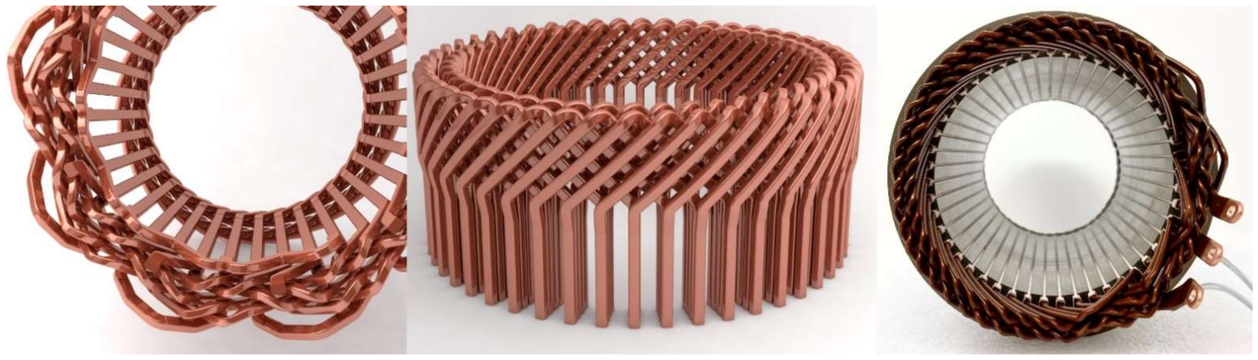
44], 3D-printed hairpin distributed windings are prototyped for E-traction motors as shown in
Figure 16. In this machine, wound copper wires are replaced by rectangular copper rods with only half winding head overhang. In addition, more than 30% torque is obtained for the same slot space.
4.3. Complete Machine Parts
With growing technology maturity, AM techniques have proven their potential to manufacture complete machine parts, such as a stator core as well as the winding, or a complete rotor with soft and hard magnetic materials. Examples are explained as follows.
Figure 17 shows a prototype of a fully 3D-printed axial flux machine. The copper windings, insulation, and the core are built simultaneously through fuse filament fabrication with a multiple-nozzle DED technique. With ceramics as insulation material, the coil can withstand a temperature of up to 300 °C [
45].
In [
46,
47,
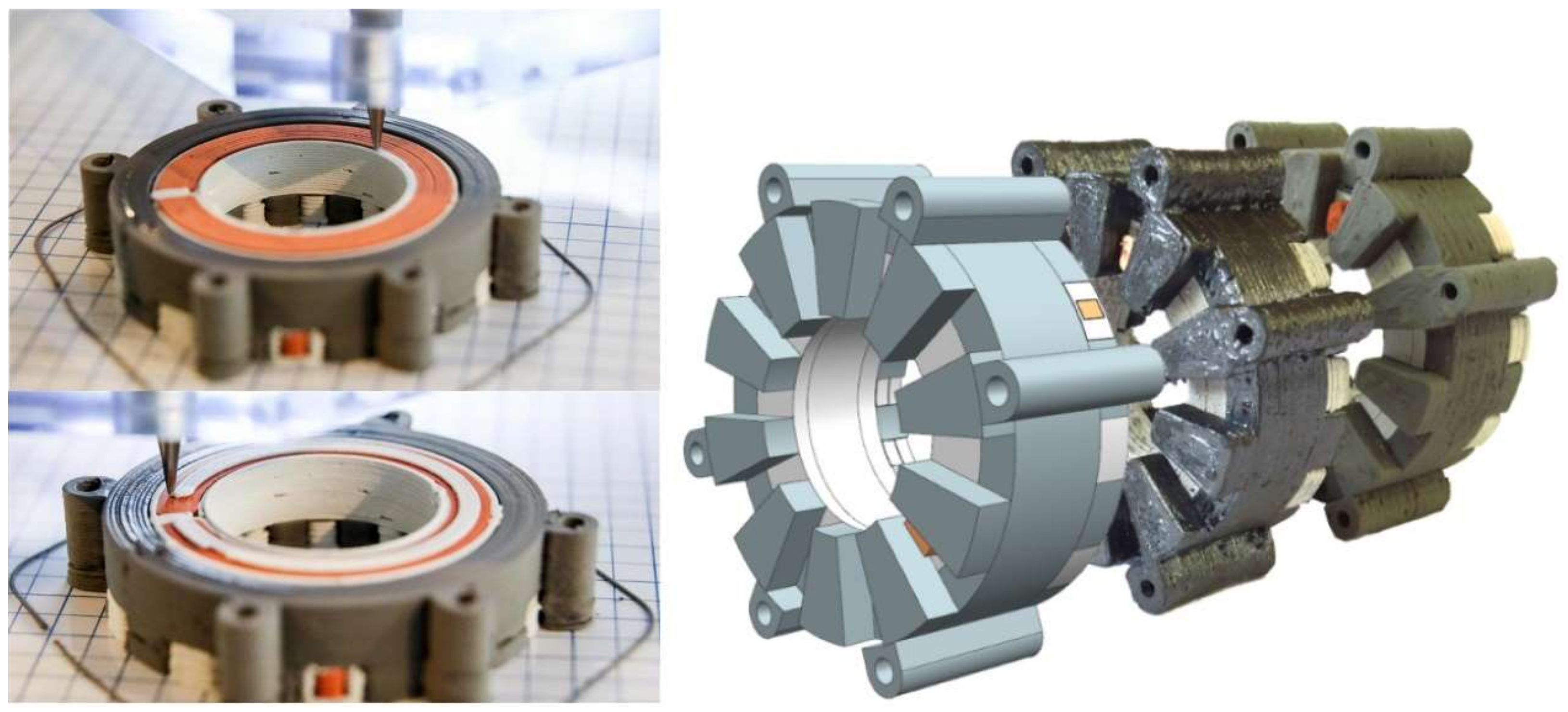
48], a conical air-gap machine is additively manufactured for automotive traction as shown in
Figure 18. A complete PM rotor is 3D printed using cold spray technology with NdFeB-Al composite powder. This technology is effective in fabricating motor parts without additional assembly steps. The machine has a promising efficiency with more than 90%. This prototype is undergoing further development so that it can be made commercially available.
4.4. Thermal-Management Parts
The growing adoption of electric vehicles (EV) is spurring the development of more powerful and more highly rated electrical machines. EV manufacturers must surmount the cooling barrier by finding cooling solutions that account for thermal efficiency, temperature uniformity, size, weight, and cost [
49]. That is why the design freedom of AM will play an important role in providing an innovative approach to EV cooling challenges, as shown in the following examples.
In [
50,
51,
52], the electrical machine windings are directly cooled using 3D-printed ceramic heat exchangers as shown in
Figure 19. By occupying the unused space between double layer concentrated windings, the power density of electrical machines is increased without affecting the electromagnetic design. The microfeatures of inner channels are optimized using different shapes for significantly improved cooling. Ceramics are selected due to their ability to withstand extremely high temperatures. As a result, the winding temperature rise is decreased by 44%. Furthermore, a continuous current density of 35.7 A/mm
2 is achieved while keeping the maximum winding temperature below 200 °C.
Figure 20 presents examples of electrical machine housing for electric vehicle (EV) applications. In [
53], the electrical machine thermal performance is improved using a unique design of liquid cooling integrated channel within the housing as shown in
Figure 20a. This complex design is prototyped easily with the aid of AM. In [
54], metal 3D-printed heat exchanger with spiral-fins is fabricated using SLM as shown in
Figure 20b. The design has superior performance and efficiency, and it can be manufactured in a very short time. In [
55], a cooling jacket with internal helix structure as shown in
Figure 20c. This function-integrated cooling water jacket is made from EOS-M-290 with 16% weight reduction and a 37% increase in the cooling performance. In [
56], a novel design is adopted, as shown in
Figure 20d, which is called Diabatix design. Unlike the spiral-like conventional thermal design, the Diabatix design has artificially designed unique patterns, offering a remarkably better performance. The thermal resistance is decreased by 25%, and the temperature uniformity is improved by 15%. In addition, the pressure drop is improved by 50%, offering a long and powerful life of the electric motor. Further, the cooling jacket weight and volume can be significantly reduced by up to 40%, meaning that less material is needed for production. It is therefore not only lighter but also cheaper.
5. Post-Processing for Metal AM
Since AM is still a relatively new industrial technology, until recently, post-processing tended to be considered of marginal importance. Today, however, as the vision of a perfected end-to-end workflow becomes a reality, post-processing operations are acknowledged as a crucial part of the supply chain [
57].
Post-processing represents the critical last single step, or multiple steps, to make sure that the product complies with highly demanding quality standards, and meets the necessary structural, mechanical, and material requirements for its final application [
57]. Some of these processes are case specific such as de-binding and sintering, which come as a second step after the part is built using binder-based technologies. However, in all cases, the built part will still need additional post-processing, such as heat treatments and surface finishing. That is why post-processes can be divided into three categories, according to the intended effects on the 3D printed part: (1) process-inherent step, (2) material properties, (3) visual appeal step.
A process-inherent step is used to free the printed part from the support material and for excess powder removal.
Material properties include the improvement of mechanical and electrical properties. For instance, the printed part can go through a controlled heat treatment protocol to relieve residual stress or improve other mechanical properties such as hardness and ductility. This annealing process can also be used for boosting the electrical conductivity.
A visual appeal step is the last touch, which includes surface treatment and finishing. In particular, the part is polished and smoothed to decrease roughness. The common surface finishing techniques include CNC machining, blasting, anodizing, and electroplating.
6. Discussion
In this paper, four different techniques of metal AM were discussed.
Table 2 shows a comparison between different AM technologies. In the powder-based techniques such as PBF and binder jetting, the main challenges are slow speeds, safety requirements, and high material costs. However, they can realize higher resolutions which are required by many applications, especially small parts with complex internal features. On the other hand, in the wire-based techniques such as wire DED and joule printing, the main challenges are the lower resolution and post-processing steps. However, these techniques are faster, safer, and lower cost. That is why they are recommended for larger, near-net-shape applications. Finally, up-to-date examples of employing metal AM in construction of electrical machines are provided including core, windings, and thermal-management parts.
7. Conclusions
This paper provides a technology overview of metal AM and its latest advancements in the manufacturing of electrical machines. Different techniques were compared in terms of maturity index, energy consumption, and cost efficiency. Powder and wire were also compared as the commonly used forms of feedstock in terms of resolution, printing speed, cost, and quality and safety.
This review paper showcased different successful examples of metal AM in electrical machine parts, especially with the use of L-PBF and DED as the most popular. Most of the aforementioned examples showed a high level of maturity with an improved electromagnetic performance. Some applications have also demonstrated a high thermal performance along with mass reduction. Still, metal AM faces different challenges, such as high process cost, post-processing challenges, and supply chain maturity issues.
Many open research questions remain, seeking further improvement in the utilization of AM in electrical machines:
the possibility of multi-material 3D printing of machine parts with high electromagnetic performance, e.g., winding along with insulation, or winding along with core;
new forms of soft magnetic materials or alloys with high magnetic permeability and low losses such as Si–Fe powder or Co–Fe.
Author Contributions
Conceptualization, A.S., M.N.I. and P.S.; methodology, A.S., M.N.I. and P.S.; software, A.S.; formal analysis, A.S., M.N.I. and P.S.; investigation, A.S., M.N.I. and P.S.; resources, A.S., M.N.I. and P.S.; data curation, A.S.; writing—original draft preparation, A.S.; writing—review and editing, M.N.I. and P.S.; visualization, M.N.I. and P.S.; supervision, P.S.; project administration, P.S.; funding acquisition, M.N.I. and P.S.; All authors have read and agreed to the published version of the manuscript.
Funding
This research is financially supported by the Research Foundation—Flanders (FWO) in the project (S001721N) entitled Multi-Material Additive Manufacturing for Electrical Machines with increased performance (AM4EM).
Conflicts of Interest
The authors declare no conflict of interest.
Appendix A
Table A1.
Magnetic properties of different AM soft magnetic materials.
Table A1.
Magnetic properties of different AM soft magnetic materials.
| Material Compositions | µmax &
Saturation Flux Density (Ms) | Hysteresis Losses | AM Technique | Heat Treatment | Ref. |
|---|
| 50Fe-49.9Co-0.1Si | µmax = 2600
Ms = 2.35 T | Comparable to
VACOFLUX 50 | SLM | 1100 °C
for 4 h | [58] |
| Fe-49Co-2V | µmax = 13,000 | Several times higher than laminated sample
@ 1.5T, 10/50 Hz | L-PBF | 700 °C
for 2 h | [59] |
| FeSi6.7 | µmax = 31,000 | 0.7 W/kg at 1T, 50 Hz | L-PBF | 1150 °C
for 1 h | [60] |
| Fe-6.9%wt.Si | µmax = 24,000 | 4 W/kg at 1T, 50 Hz | SLM | 1150 °C
for 1 h | [61] |
| Fe-80%Ni | Ms = 550 Am2/kg | BH loop is available
Losses are not calculated | SLM | non | [62] |
| Ni-Fe14-Cu5-Mo4 | Ms = 0.33 T | BH loop is available
Losses are not calculated | SLM | non | [63] |
References
- ESA-Automation. Additive Manufacturing in Industry 4.0. Available online: https://www.esa-automation.com/en/additive-manufacturing-in-industry-4-0 (accessed on 11 December 2021).
- Cost of Metal Additive Manufacturing; AM-Power-Report. Available online: https://am-power.de/studies/cost-of-metal-additive-manufacturing (accessed on 11 December 2021).
- Barz, A.; Buer, T.; Haasis, H.-D. A Study on the Effects of Additive Manufacturing on the Structure of Supply Networks. IFAC-PapersOnLine 2016, 49, 72–77. [Google Scholar] [CrossRef]
- El-Refaie, A.; Osama, M. High specific power electrical machines: A system perspective. CES Trans. Electr. Mach. Syst. 2019, 3, 88–93. Available online: https://doi.org/10.30941/CESTEMS.2019.00012 (accessed on 11 January 2022). [CrossRef]
- Selema, A. Development of a Three-Phase Dual-Rotor Magnetless Flux Switching Generator for Low Power Wind Turbines. IEEE Trans. Energy Convers. 2020, 35, 828–836. [Google Scholar] [CrossRef]
- Selema, A. Design and analysis of a brushless flux switching generator for rooftop wind turbines. In Proceedings of the 2019 IEEE Conference on Power Electronics and Renewable Energy (CPERE), Aswan, Egypt, 23–25 October 2019. [Google Scholar]
- Selema, A.; Osheba, D.S.M.; Tahoon, S.M.R.; El-Shanawany, M.M. Design and analysis of a three-phase brushless flux switching generator for aircraft ground power units. IET Electr. Power Appl. 2019, 13, 154–161. [Google Scholar] [CrossRef]
- Said Selema, A.; Shaban Osheba, D.; Mustafa El-Shanawany, M.; Mohamed Tahoun, S. Design and Analysis of a Brushless Three Phase Flux Switching Generator for Aircraft Auxiliary Power Unit. In Proceedings of the IEEE 2018 Twentieth International Middle East Power Systems Conference (MEPCON), Nasr City, Egypt, 18–20 December 2018; pp. 198–202. [Google Scholar]
- Ghassemi, M. High power density technologies for large generators and motors for marine applications with focus on electrical insulation challenges. High Volt. 2020, 5, 7–14. [Google Scholar] [CrossRef]
- Lamichhane, T.N.; Sethuraman, L.; Dalagan, A.; Wang, H.; Keller, J.; Paranthaman, M.P. Additive manufacturing of soft magnets for electrical machines—A review. Mater. Today Phys. 2020, 15, 100255. [Google Scholar] [CrossRef]
- Metal Additive Manufacturing Technology; AM-Power-Report. Available online: https://additive-manufacturing-report.com/additive-manufacturing-metal-technology (accessed on 12 December 2021).
- Additivemanufacturing.media AM. 101: NanoParticle Jetting (NPJ). Available online: https://www.additivemanufacturing.media/articles/am-101-nanoparticle-jetting-npj (accessed on 12 December 2021).
- Zou, Y. Cold Spray Additive Manufacturing: Microstructure Evolution and Bonding Features. Accounts Mater. Res. 2021, 2, 1071–1081. [Google Scholar] [CrossRef]
- Khorasani, A.; Gibson, I.; Veetil, J.K.; Ghasemi, A.H. A review of technological improvements in laser-based powder bed fusion of metal printers. Int. J. Adv. Manuf. Technol. 2020, 108, 191–209. [Google Scholar] [CrossRef]
- Van Praet, K. Tips and Tricks for Metal 3D Printing: Recoaters. Available online: https://www.materialise.com/en/blog/metal-3D-printing-recoaters (accessed on 11 December 2021).
- Bambach, M. Metal Additive Manufacturing: Chapter 5: Laser-Based Metal Additive Manufacturing. Available online: https://www.metal-am.com/metal-additive-manufacturing-magazine (accessed on 12 December 2021).
- Directed Energy Deposition—Synergy Additive Manufacturing. Available online: https://synergyadditive.com/directed-energy-deposition (accessed on 13 December 2021).
- Taminger, K.M.B. Electron Beam Additive Manufacturing. Available online: https://www.sciaky.com/additive-manufacturing/electron-beam-additive-manufacturing-technology (accessed on 15 December 2021).
- Nanalyze, D. Alloy Joule Printing—Fast, Low-Cost Metal 3D Printing. Available online: https://www.nanalyze.com/2019/03/joule-fast-low-cost-metal-3d-printing (accessed on 11 December 2021).
- Digital Alloys. Economics of Metal Additive Manufacturing—Digital Alloys. Available online: https://www.ramlab.com/resources/ded-101/ (accessed on 30 January 2022).
- Renishaw Industrial Applications of Renishaw Metal Additive Manufacturing Technology. Available online: https://www.renishaw.com/en/industrial-applications-of-renishaw-metal-additive-manufacturing-technology--15256 (accessed on 30 January 2022).
- Blakey-Milner, B.; Gradl, P.; Snedden, G.; Brooks, M.; Pitot, J.; Lopez, E.; Leary, M.; Berto, F.; du Plessis, A. Metal additive manufacturing in aerospace: A review. Mater. Des. 2021, 209, 110008. [Google Scholar] [CrossRef]
- Fish, G.E. Soft magnetic materials. Proc. IEEE 1990, 78, 947–972. [Google Scholar] [CrossRef]
- Urban, N.; Meyer, A.; Leckel, M.; Leder, M.; Franke, J. Additive Manufacturing of an Electric Drive a Feasability Study. In Proceedings of the IEEE 2018 International Symposium on Power Electronics, Electrical Drives, Automation and Motion (SPEEDAM), Amalfi, Italy, 20–22 June 2018; pp. 1327–1331. [Google Scholar]
- Wits, W.W.; Jafari, D. Experimental Performance of a 3D-Printed Hybrid Heat Pipe-Thermosyphon for Cooling of Power Electronics. In Proceedings of the IEEE 2018 24th International Workshop on Thermal Investigations of ICs and Systems (THERMINIC), Stockholm, Sweden, 26–28 September 2018; pp. 1–6. [Google Scholar]
- Metsä-Kortelainen, S.; Lindroos, T.; Savolainen, M.; Jokinen, A.; Revuelta, A.; Pasanen, A.; Ruusuvuori, K.; Pippuri, J. Manufacturing of topology optimized soft magnetic core through 3D printing. In Proceedings of the NAFEMS Exploring the Design Freedom of Additive Manufacturing through Simulation, Helsinki, Finland, 22–23 November 2016. [Google Scholar]
- Freeman, F.S.H.B.; Lincoln, A.; Sharp, J.; Lambourne, A.; Todd, I. Exploiting thermal strain to achieve an in-situ magnetically graded material. Mater. Des. 2019, 161, 14–21. [Google Scholar] [CrossRef]
- Zhang, Z.-Y.; Jhong, K.J.; Cheng, C.-W.; Huang, P.-W.; Tsai, M.-C.; Lee, W.-H. Metal 3D printing of synchronous reluctance rotor. In Proceedings of the 2016 IEEE International Conference on Industrial Technology (ICIT), Taipei, Taiwan, 14–17 March 2016; pp. 1125–1128. [Google Scholar]
- Tseng, G.-M.; Jhong, K.-J.; Tsai, M.-C.; Huang, P.-W.; Lee, W.-H. Application of additive manufacturing for low torque ripple of 6/4 switched reluctance motor. In Proceedings of the 2016 19th International Conference on Electrical Machines and Systems, Chiba, Japan, 13–16 November 2016; pp. 1–4. [Google Scholar]
- Urbanek, S.; Frey, P.; Magerkohl, S.; Zimmer, D.; Tasche, L.; Schaper, M.; Ponick, B. Design and Experimental Investigation of an Additively Manufactured PMSM Rotor. In Proceedings of the 2021 IEEE International Electric Machines & Drives Conference (IEMDC), Hartford, CT, USA, 17–20 May 2021; pp. 1–6. [Google Scholar]
- Hosek, M.; Krishnasamy, J.; Sah, S.; Bashaw, T.; American Society of Mechanical Engineers. Spray-Formed Hybrid-Field Electric Motor. In Proceedings of the 9th Frontiers in Biomedical Devices, Charlotte, NC, USA, 21–24 August 2016; Volume 3. [Google Scholar]
- Selema, A.; Ibrahim, M.N.; Sprangers, R.; Sergeant, P. Effect of Using Different Types of Magnet Wires on the AC Losses of Electrical Machine Windings. In Proceedings of the 2021 IEEE International Electric Machines & Drives Conference (IEMDC), Hartford, CT, USA, 17–20 May 2021; pp. 1–5. [Google Scholar]
- Jagdale, V.; Tangudu, J. Topology Optimized End Winding for Additively Manufactured Induction Motor with Distributed Winding. Available online: https://trid.trb.org/view/1835255 (accessed on 22 December 2021).
- Saari, M.; Cox, B.; Richer, E.; Krueger, P.S.; Cohen, A.L. Fiber Encapsulation Additive Manufacturing: An Enabling Technology for 3D Printing of Electromechanical Devices and Robotic Components. 3D Print. Addit. Manuf. 2015, 2, 32–39. [Google Scholar] [CrossRef]
- Cox, B.; Saari, M.; Xia, B.; Richer, E.; Krueger, P.S.; Cohen, A.L. Fiber Encapsulation Additive Manufacturing: Technology and Applications Update. 3D Print. Addit. Manuf. 2017, 4, 116–119. [Google Scholar] [CrossRef]
- Vialva, T. Trumpf Introduces Precious Metal and Copper 3D Printing Powered by Green Laser. Available online: https://3dprintingindustry.com/news/trumpf-introduces-precious-metal-and-copper-3d-printing-powered-by-green-laser-143689 (accessed on 20 December 2021).
- Ranjan, R.; Tangudu, J. Thermal design of high power-density additively-manufactured induction motors. In Proceedings of the 2014 IEEE Energy Conversion Congress and Exposition (ECCE), Pittsburgh, PA, USA, 14–18 September 2014; pp. 1325–1331. [Google Scholar]
- Wu, F.; EL-Refaie, A.M.; Al-Qarni, A. Additively Manufactured Hollow Conductors for High Specific Power Electrical Machines: Aluminum vs Copper. In Proceedings of the 2021 IEEE Energy Conversion Congress and Exposition (ECCE), Vancouver, BC, Canada, 10–14 October 2021; pp. 4397–4404. [Google Scholar]
- Simpson, N.; North, D.J.; Collins, S.M.; Mellor, P.H. Additive Manufacturing of Shaped Profile Windings for Minimal AC Loss in Electrical Machines. IEEE Trans. Ind. Appl. 2020, 56, 2510–2519. [Google Scholar] [CrossRef] [Green Version]
- Simpson, N.; Mellor, P.H. Additive Manufacturing of Shaped Profile Windings for Minimal AC Loss in Electrical Machines. In Proceedings of the 2018 IEEE Energy Conversion Congress and Exposition (ECCE), Portland, OR, USA, 23–27 September 2018; pp. 5765–5772. [Google Scholar]
- Ayat, S.; Simpson, N.; Daguse, B.; Rudolph, J.; Lorenz, F.; Drury, D. Design of Shaped-Profile Electrical Machine Windings for Multi-Material Additive Manufacture. In Proceedings of the IEEE 2020 International Conference on Electrical Machines (ICEM), Gothenburg, Sweden, 23–26 August 2020; pp. 1554–1559. [Google Scholar]
- Robinson, J.; Simpson, N. Functional Multi-Material Coil Winding and TPMS Heat Exchanger. Available online: https://www.wlv.ac.uk/research/institutes-and-centres/centre-for-engineering-innovation-and-research/amfm-research-group (accessed on 19 December 2021).
- Additive Drives. Racing Engine with 3D-Printed Coils. Available online: https://www.additive-drives.de/en/project/racing-engine (accessed on 20 December 2021).
- Additive Drives. 3D-Printed Hairpin Windings for E-traction Motors. Available online: https://www.additive-drives.de/en/project/e-traction-motor (accessed on 21 December 2021).
- Travitzky, N.; Bonet, A.; Dermeik, B.; Fey, T.; Filbert-Demut, I.; Schlier, L.; Schlordt, T.; Greil, P. Additive Manufacturing of Ceramic-Based Materials. Adv. Eng. Mater. 2014, 16, 729–754. [Google Scholar] [CrossRef]
- Lamarre, J.-M.; Bernier, F. Permanent Magnets Produced by Cold Spray Additive Manufacturing for Electric Engines. J. Therm. Spray Technol. 2019, 28, 1709–1717. [Google Scholar] [CrossRef]
- Krishnasamy, J.; Hosek, M. Spray-Formed Hybrid-Field Traction Motor. In Proceedings of the SAE World Congress Experience, Detroit, MI, USA, 4–6 April 2017; pp. 1–7. [Google Scholar]
- Hošek, M.; Krishnasamy, J.; Sah, S.; Bashaw, T. Spray-Formed Hybrid-Field Electric Motor. In Proceedings of the 2016 ASME Design Engineering Technical Conference, Vancouver, BC, Canada, 17–21 July 2016; Volume 3. [Google Scholar]
- Diabatix Efficient Thermal Design. Available online: https://www.diabatix.com/blog (accessed on 21 December 2021).
- Sixel, W.; Liu, M.; Nellis, G.; Sarlioglu, B. Ceramic 3D Printed Direct Winding Heat Exchangers for Improving Electric Machine Thermal Management. In Proceedings of the 2019 IEEE Energy Conversion Congress and Exposition (ECCE), Baltimore, MD, USA, 29 September–3 October 2019; pp. 769–776. [Google Scholar]
- Sixel, W.; Liu, M.; Nellis, G.; Sarlioglu, B. Cooling of Windings in Electric Machines via 3-D Printed Heat Exchanger. IEEE Trans. Ind. Appl. 2020, 56, 4718–4726. [Google Scholar] [CrossRef]
- Sixel, W.; Liu, M.; Nellis, G.; Sarlioglu, B. Cooling of Windings in Electric Machines via 3D Printed Heat Exchanger. In Proceedings of the 2018 IEEE Energy Conversion Congress and Exposition (ECCE), Portland, OR, USA, 23–27 September 2018; pp. 229–235. [Google Scholar]
- Silbernagel, C. Nottingham PhD Student Wins Additive World Design Challenge Award. Available online: https://exchange.nottingham.ac.uk/blog/%0Aphd-student-wins-additive-world-design-challenge-award (accessed on 21 December 2021).
- HBD Metal 3D Printing Advantages. Available online: https://en.hb3dp.com/app1.html (accessed on 21 December 2021).
- EPMA Cooling jacket with internal helix structure. Available online: https://www.epma.com/spotlight-on-pm/cooling-jacket-with-internal-helix-structure (accessed on 23 December 2021).
- Vervecken, L. Diabatix Artificial Intelligence Is Driving Better Cooling for Critical EV Components. Available online: https://www.diabatix.com/blog/ai-driving-better-ev-cooling (accessed on 19 December 2021).
- Aniwaa Guide to Post-Processing for Metal AM. Available online: https://www.aniwaa.com/guide/post-processing/guide-post-processing-metal-am (accessed on 19 December 2021).
- Johnson, F.; Osama, M.; Jassal, A.K.; Adharapurapu, R.R. Method of Heat-Treating Additively-Manufactured Ferromagnetic Components. U.S. Patent 10,946,444, 16 March 2021. [Google Scholar]
- Riipinen, T.; Metsä-Kortelainen, S.; Lindroos, T.; Keränen, J.S.; Manninen, A.; Pippuri-Mäkeläinen, J. Properties of soft magnetic Fe-Co-V alloy produced by laser powder bed fusion. Rapid Prototyp. J. 2019, 25, 699–707. [Google Scholar] [CrossRef]
- Goll, D.; Schuller, D.; Martinek, G.; Kunert, T.; Schurr, J.; Sinz, C.; Schubert, T.; Bernthaler, T.; Riegel, H.; Schneider, G. Additive manufacturing of soft magnetic materials and components. Addit. Manuf. 2019, 27, 428–439. [Google Scholar] [CrossRef]
- Garibaldi, M. Laser Additive Manufacturing of Soft Magnetic Cores for Rotating Electrical Machinery: Materials Development and Part Design. Ph.D. Thesis, University of Nottingham, Nottingham, UK, 2018. [Google Scholar]
- Zhang, B.; Fenineche, N.-E.; Liao, H.; Coddet, C. Magnetic properties of in-situ synthesized FeNi3 by selective laser melting Fe-80%Ni powders. J. Magn. Magn. Mater. 2013, 336, 49–54. [Google Scholar] [CrossRef]
- Zhang, B.; Fenineche, N.-E.; Liao, H.; Coddet, C. Microstructure and Magnetic Properties of Fe–Ni Alloy Fabricated by Selective Laser Melting Fe/Ni Mixed Powders. J. Mater. Sci. Technol. 2013, 29, 757–760. [Google Scholar] [CrossRef]
| Publisher’s Note: MDPI stays neutral with regard to jurisdictional claims in published maps and institutional affiliations. |
© 2022 by the authors. Licensee MDPI, Basel, Switzerland. This article is an open access article distributed under the terms and conditions of the Creative Commons Attribution (CC BY) license (https://creativecommons.org/licenses/by/4.0/).


