Article

Development of a Hydraulic System for the Automatic Expansion of Powered Roof Support

1
Center of Hydraulics DOH Ltd., ul. Konstytucji 147, 41-906 Bytom, Poland
2
Polska Grupa Górnicza S.A., ul. Powstańców 30, 40-039 Katowice, Poland
3
KWK Ruda Ruch Halemba, ul. Halembska 160, 41-717 Ruda Śląska, Poland
4
Department of Trade and Marketing, Siberian Federal University, 79 Svobodny Ave., 660041 Krasnoyarsk, Russia
5
Department of Open Pit Mining, T.F. Gorbachev Kuzbass State Technical University, 28 Vesennya Str., 650000 Kemerovo, Russia
6
School of Core Engineering Education, National Research Tomsk Polytechnic University, 30 Lenina Str., 634050 Tomsk, Russia
*
Author to whom correspondence should be addressed.
Energies 2022, 15(3), 680; https://doi.org/10.3390/en15030680
Submission received: 17 December 2021 / Revised: 11 January 2022 / Accepted: 13 January 2022 / Published: 18 January 2022
(This article belongs to the Special Issue Green Economy and Sustainable Development)

Abstract

:
A mechanical support in a longwall complex requires proper supervision and control of operating parameters because it is responsible for the safety of machines and workers. Its main functions are to protect the excavation against the adverse effects of rock mass and to move it along with the operational progress of the shearer and the scraper conveyor. In the era of Industry 4.0 as well as green economy and sustainable development, the development of machines and devices included in the longwall complex is an important area of invention. When it comes to the mechanical support included in the longwall complex, the authors propose changes to the hydraulic control system. The main purpose of the work was to develop a system that can automatically expand the legs of the powered support. Tests were carried out under real conditions while equipping the support section with a prototypical hydraulic system and with a system monitoring the correct operation of the prototype. This article presents the development of a prototypical installation under real conditions for testing on a longwall. The innovative solution proposed by the authors consisted of introducing a prototypical double valve block into the hydraulic system of the housing, which enables the function of automatic section expansion. The authors proposed a solution aimed at shortening the work time of the powered-support-section operator. The research results made it possible to evaluate the usefulness of the proposed solution. This type of solution can be considered technical support in the process of coal mining in an underground mine. Analysis presented in this paper, along with results from research conducted and its conclusions, can be of practical help to enclosure users to improve reliability and achieve optimal performance.

1. Introduction

Continuous technological progress and economic development in the era of the fourth industrial revolution, referred to as Industry 4.0, require companies to constantly change and implement innovative technical solutions [1,2,3]. This issue also applies to the mining industry of solid, liquid and gaseous minerals, which is expected to intensify production while minimizing negative impacts on the environment [4,5,6]. This determines the conduct of research and the search for new solutions—both in terms of improving the reliability of machines [7,8,9,10] and optimizing production processes [11,12,13,14,15,16,17] as well as improving work safety [18,19,20,21,22] and caring for the environment [23].
Sustainable development is also observed in hard-coal mining, which deals with the intensification of the mining process and an increase in efficiency. This situation is accompanied by the deterioration of mining and geological conditions, an increase in natural hazards and a generation of new operational problems, among others related to the selection of progressively lower layers of coal beds (over 1000 m). It all adds up to ever-higher requirements for the level of reliability of machines, in particular longwall systems, while needing to maintain the required level of safety [24,25,26,27].
In order to meet the previously mentioned requirements and constantly improve the production efficiency and safety of the crew, it is necessary to search for new solutions in the field of coal-bed selection [28,29,30,31,32,33], improve working conditions and minimize hazards [34,35] as well as conduct research aimed at improving the reliability of machines [36,37]. A key element influencing the increase in efficiency of the mining process and the increase in safety is automation of the longwall complex [38,39,40,41,42,43].
The powered support (Figure 1) is one of the key elements of longwall systems, next to the extracting machine (shearer or plow) and the scraper conveyor. Its main task is to control the roof and protect the crew working along the wall and other machines against the fall of the roof rocks and against the chunks of coal falling off the face of the longwall [44,45,46,47]. The support moves behind the front of the wall and, at the same time, is responsible for moving the gutters of the wall scraper conveyor. In order for the support to perform its functions properly, it is important to select it correctly, taking into account the mining and geological conditions and parameters of the wall. Recent research in the development of supports is presented in the works [48,49,50,51,52,53,54,55,56,57].
Currently, leg and protection supports with a lemniscate canopy guiding mechanism are commonly used. In this type of support, the canopy is pivotally connected to the sill piece by means of a shield system as well as by means of front and rear connectors, called lemniscates. This type of structure makes it possible for the end of the canopy to move along the lemniscate curve, almost perpendicularly to the floor, thanks to which the roof is protected up to the sidewall [41].
The main element of the hydraulic system of powered supports are hydraulic legs, which are expanded between the canopy and the sill piece. Their parameters largely determine the quality of the support of the section. An additional actuator connected with the canopy and the shield system stabilizes the section and allows adjustment of the angle of the canopy inclination in relation to the sill piece. Other elements of power hydraulics are the shifter, actuators of the tilting and extending canopy, actuators of the face of the wall cover and transition area, the sill piece lifting actuator and corrective actuators [41].
Each actuator is controlled by a hydraulic distributor. The distributors are connected with hydraulic locks, consisting of controlled check valves and pressure limiting valves, which also have a safety function against overloads resulting from impact of rock mass. Each section of the powered support can be cut off with a shut-off valve, and a check valve installed in front of the drain line protects the section against pressure [41].
The support operation cycle can be divided into the following phases: drawing off, moving the sections, expanding the support and the apparatus for repositioning the conveyor. All functions are performed by means of hydraulic actuator in conjunction with the control hydraulics (Figure 2). Individual phases of the work cycle may be implemented in an adjacent, pilot or electro-hydraulic control system.
This paper focuses on the development of the automatic expansion of the powered support system. An innovative solution was proposed by introducing a prototypical double valve block into the hydraulic system, which enables the function of automatic expansion of the housing. In this regard, the prototypical system was tested and analyzed under real conditions. The purpose of this study was to determine the usefulness of a prototypical system with the automatic-expansion function. The proposed changes to the hydraulic system of the mechanical casing are described in Section 2. Results from the tests, together with analysis of powered roof-support operation before application of the new solution and after introducing changes in the hydraulic system, are presented in Section 3. Section 4 discusses effects from the new solution.

2. Materials and Methods

For proper operation of the support and ensured good conditions for maintaining the roof of the excavation, selection of the appropriate support, which entails choosing the force with which the support acts on the roof, is an important factor. Depending on the phase of the support operation cycle, there are three types of load-carrying capacities: initial, nominal and working [52].
Initial load capacity is obtained when the support is expanded, and it depends on the supply pressure in the main supply line in the wall. After the support takes over the pressure of the roof rocks, the section’s load capacity changes to the working-load capacity. In contrast, the nominal load capacity is the force at which the leg reveals its compliance, which depends on the opening pressure of the safety valves in the leg valve block [52].

2.1. Carrying-Load-Capacity Calculation Model

Taking into account the above definitions, the carrying-load capacity of a support leg can be described with the following relations [52]:
-
Initial load capacity
F w = π d 2 4 · p z a s ,   N
where
d—leg working diameter (mm);
pzas—supply pressure (pressure in the supply line) (MPa);
N—the SI unit of force (newton).
-
Working load
F r = π d 2 4 · p r o b ,   N
where
prob—leg working diameter (MPa);
-
Nominal load capacity
F n = π d 2 4 · p n o m   ,   N
where
pnom—nominal pressure (safety valve opening pressure) (MPa).
It should be noted in the case of double-telescopic legs, during the transition of the work of the leg from the 1st to the 2nd degree, there will be a decrease in its load-carrying capacity, resulting from the smaller diameter of the 2nd-stage cylinder. The value of the working-load capacity is between the initial load capacity and the nominal load capacity. The nominal load capacity is the maximum capacity the support can achieve.
F w F r F n
Selection of the appropriate load capacity is of great importance for controlling the roof properly. If the initial load capacity is too high, the roof rocks may be destroyed. On the other hand, if the nominal load capacity is too high, the effect of the coal-bed stress relief caused by the pressure of the roof may disappear. Coal-bed stress relief has a direct impact on the mining process, as it causes the initial crushing of the unmined coal near the face of the wall, which means the miner uses less energy and increases the proportion of coarse-grained classes.

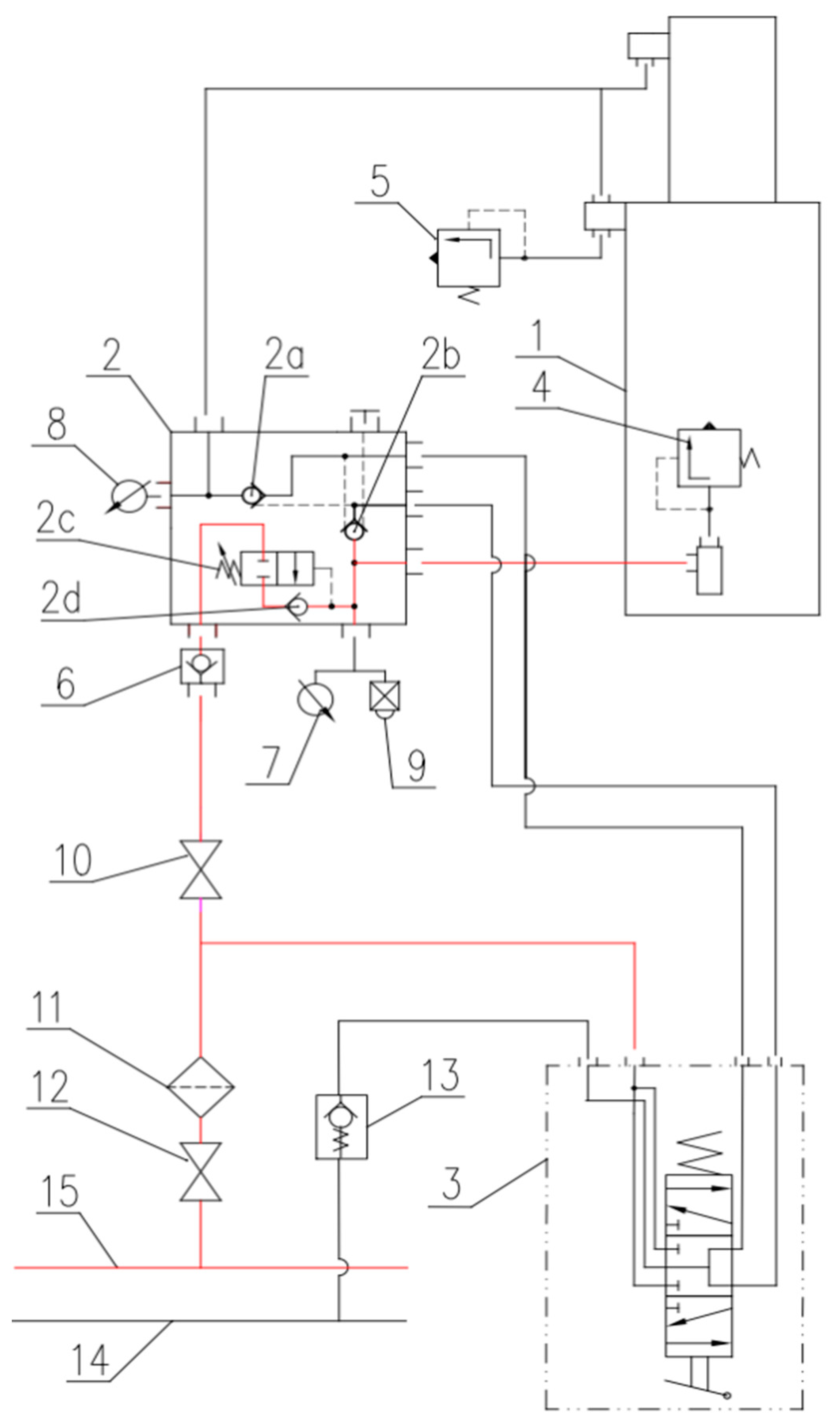
2.2. Layout Concept for Automatic Expansion of Legs

A special hydraulic system was tested (Figure 3), which was equipped with a double valve block with an automatic-expansion function. This system consisted of a threshold valve (2c) with a check valve (2d) and was connected to the supply line (15) through a second check valve (6) and a shut-off valve (10). The threshold valve (2c), which was located in the block, had an opening pressure setting of 9 MPa. This meant the automatic pressure function did not work below this number. When the pressure of 9 MPa was exceeded during leg expansion, the automatic expansion system was turned on. It ensured the expansion of the leg to the required initial equal-load capacity to the maximum value of the pressure in the supply line despite the fact that the expansion function was interrupted by the operator.
The use of a double valve block (2) in the hydraulic system for the automatic expansion of the support legs is a necessary condition because it prevents a pressure drop in the space under the piston of a leg in the case of internal leakage. Its purpose is to ensure initial- and working-load capacities are attained. Additionally, this system was equipped with an excess flow valve (5) in the piston space. This valve is designed to protect against damage to the hydraulic lines connecting the valve bank with the space over the piston of the leg. It is effective protection in the case of internal leakage and increase in pressure in the space over the piston to a value exceeding the strength of the connecting pipes as well as when the expansion-control function is performed in the section of a single leg. The automatic expansion system of an additional check valve (6), which was connected in series with this system, was implemented. It aimed to eliminate the possibility of liquid flowing back to the main supply line in the event of contamination of the check valve (2d).
In the new solution proposed by the authors, the system automatically equalizes the pressure in the plunger space of the legs to the required value. In the event of pressure fluctuations in the supply line, the new system will automatically react when the pressure in the line increases and will then compensate the pressure in the piston cavity of the leg to achieve the required initial and operating supports. In addition, the new system automatically reacts to any pressure drops that may occur between the working cycles of a mechanically powered roof support, e.g., due to internal leaks. If a drop in pressure is detected in the subpiston space of the leg, the system automatically repressurizes to ensure stable operation of the section. The pressure in the legs is equalized automatically, without operator intervention—unlike the classic solution. In a classical system, the section operator would have to continuously monitor the pressure in the racks and the supply line to provide the required support. If the section operator does not notice the pressure drop, the section will be operating with too little support.

3. Results

The tests were carried out in a longwall, where an automatic-expansion system was installed in the powered support section. In order to obtain the test results, the proposed solution was equipped with a wireless pressure-monitoring system. Pressure sensors in the piston space were installed in the stands of the powered support. Pressure was measured in a continuous system with a sampling rate of 1 s. Thanks to this, it was possible to constantly monitor the operation of the powered support equipped with the hydraulic system for automatic leg expansion. Tests and analysis were conducted on the basis of the pressure monitoring records in the powered support legs for selected sections of the powered support. Analysis was carried out for two specific stages of longwall exploitation:
-
Before the assembly of the prototypical system of automatic leg expansion;
-
After installing the automatic leg expansion.

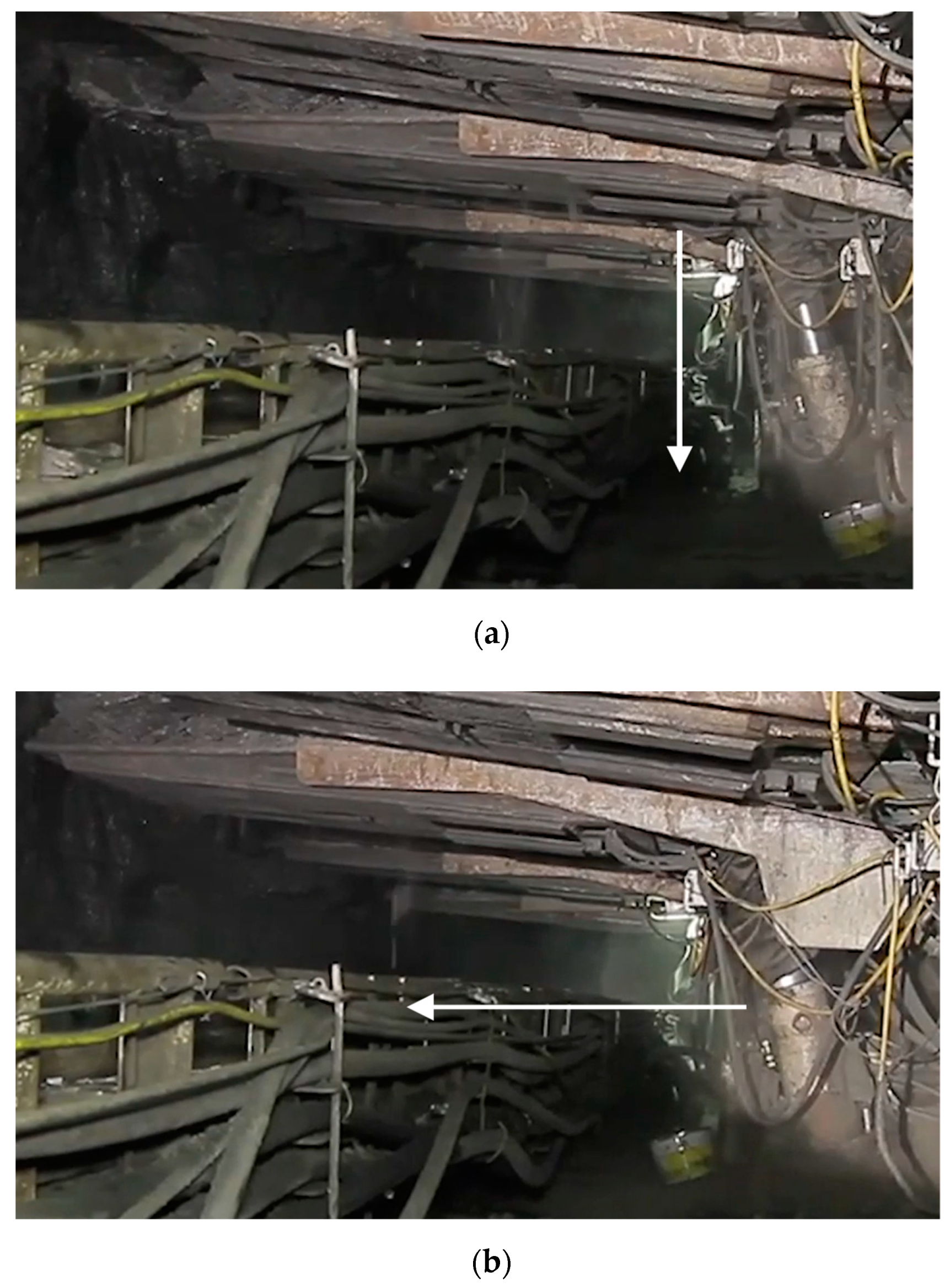
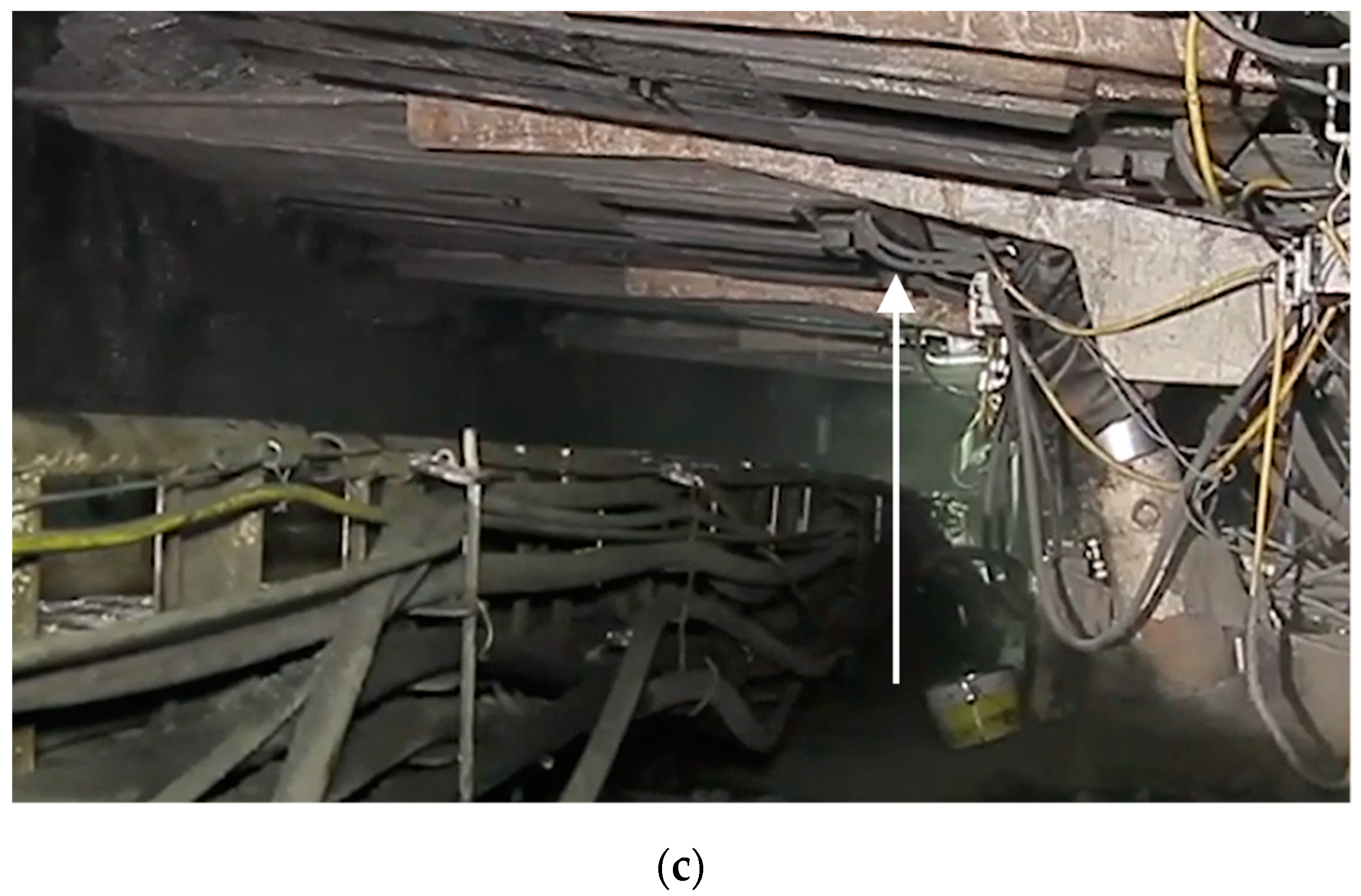
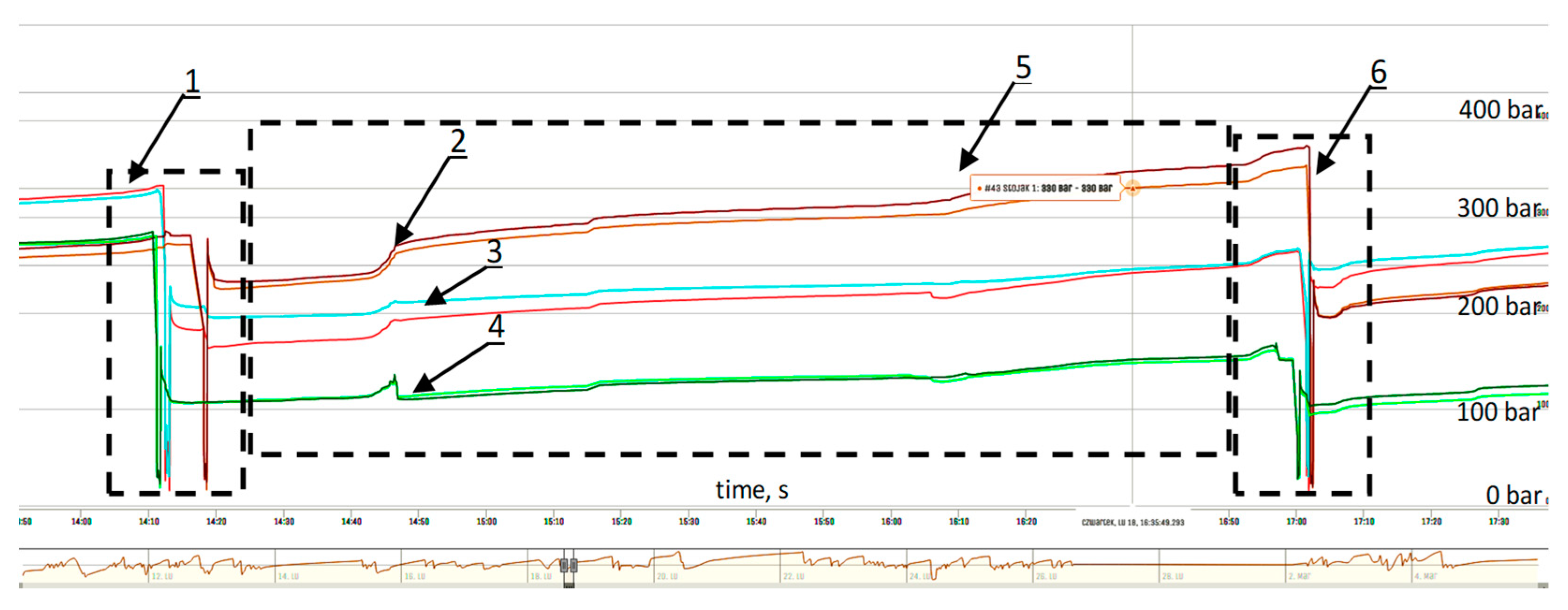
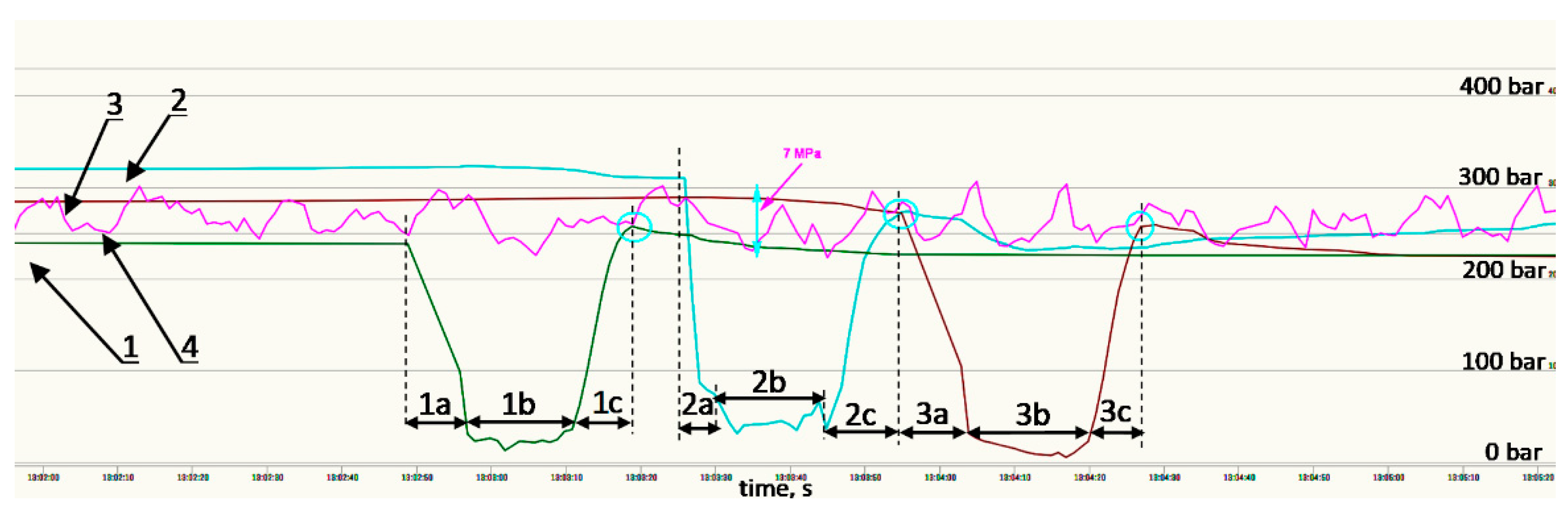
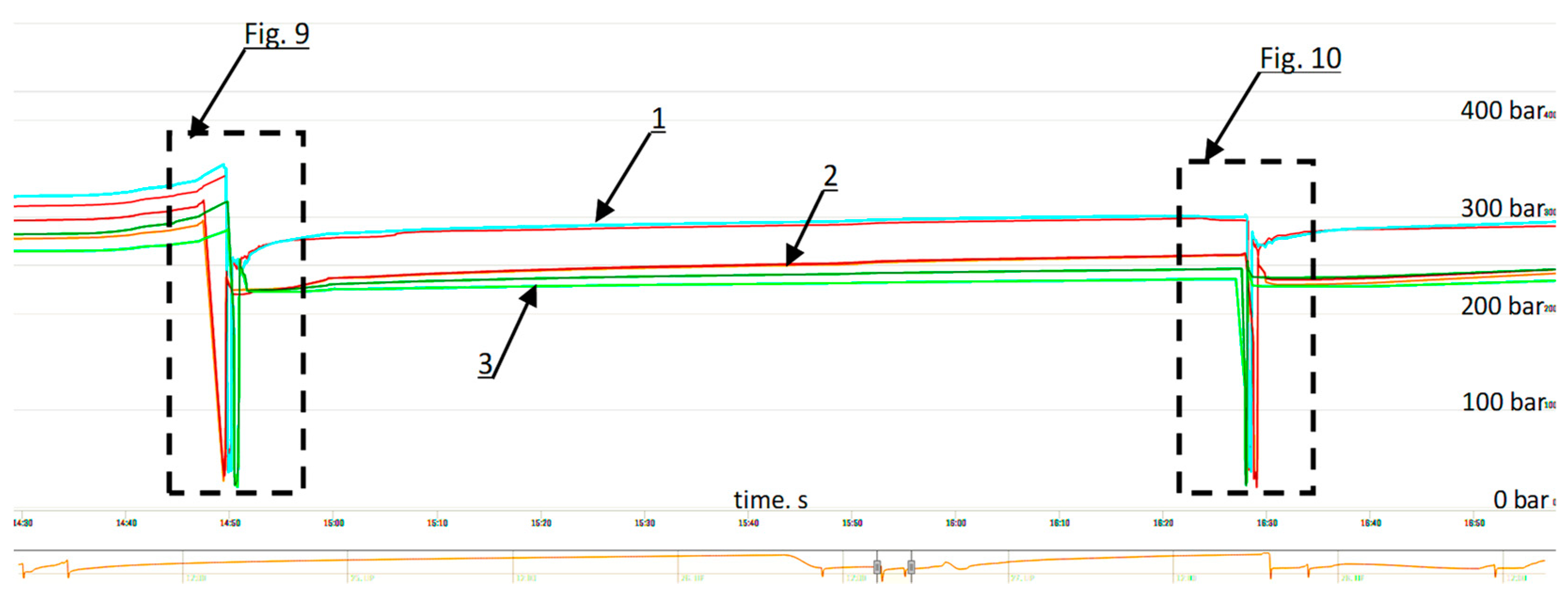
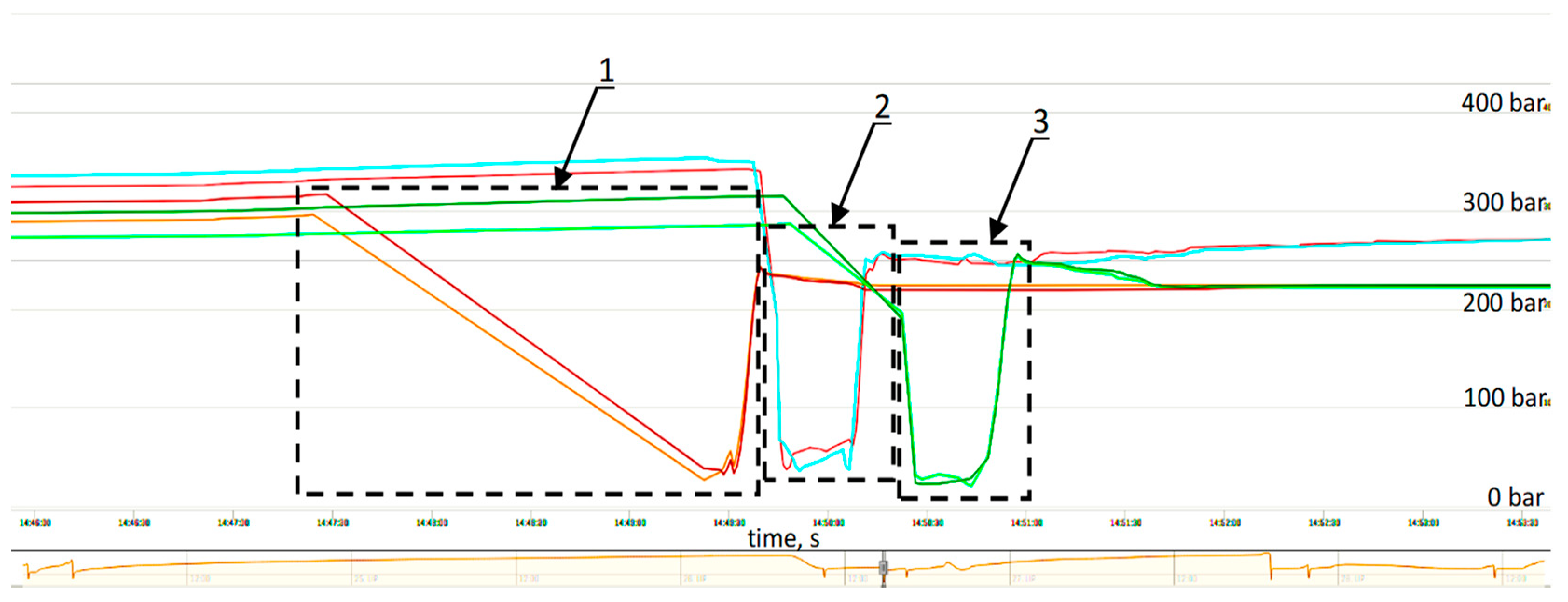
3.1. Analysis of the Expansion of a Powered Support Section in a Longwall

The presented diagram (Figure 4) shows a clear drop in pressure in the legs after the completion of the expansion operation of the powered support. The presented pressure drop in the initial period of the expansion of the powered support results from the local conditions of interoperability between the support and the rock mass as well as from the influence of the adjacent sections in the longwall and the characteristics of the safety valves used in the hydraulic system. This pressure drop can change from 2 to 5 MPa in a matter of minutes. The analyzed charts show a large pressure difference between the expanded sections, amounting to over 10 MPa. A similar measurement is visible in the previous and next expansion cycles. The pressure difference is the result of interrupting the expansion of the support before obtaining the required initial load-bearing capacity. In the diagram (Figure 4), the pressure difference between the legs of sections 43, 44 and 45 is 20 MPa.

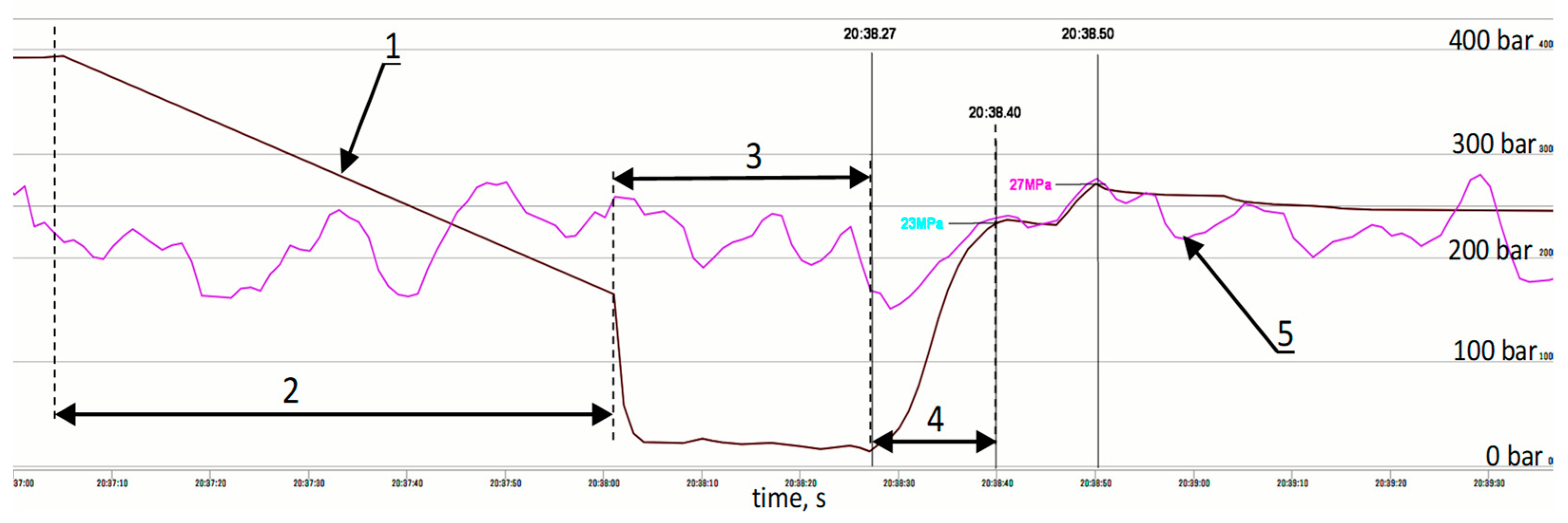
3.2. Analysis of the Measurements for the Expansion of the Powered Support before the Installation of the Automatic System

The presented Figure 5 includes the measurement of the powered support operation prior to the installation of the automatic leg-expansion system for supports no. 43, 44 and 45. The use of a wireless pressure-monitoring system made it possible to obtain the measurements. The measurement shows the minimum value of the initial load capacity as a result of which the pressure difference between supports no. 43, 44 and 45 is slight, up to 4 MPa.
Eliminating the pressure difference (5 MPa) is quite difficult because it results from the nature of the pressure change in the main supply line. The pressure change is illustrated in detail in Figure 6. This diagram clearly shows that the value of the final pressure in the legs during expansion depends on the instantaneous pressure value in the supply line.
Figure 7 shows the expansion of the support at a time when the pressure in the main power line is below the value to which the mechanical support should be expanded. Using the pressure-monitoring light signal, the support operator receives information whether the pressure in the main line will increase, allowing the expansion of the support to the required value of initial load capacity. However, this is done at the expense of extending the support’s expansion time, which may affect the effectiveness of the longwall exploitation.

3.3. Analysis of the Measurements for the Expansion of the Powered Support before the Installation of the Automatic System

Figure 8 shows the pressure course in the legs for powered support no. 43, 44 and 45 in the longwall after assembling the prototypical system in order to verify its correct operation under real conditions. Analyzing the measurement, it can be concluded that powered support no. 44 reaches the maximum value of the main-line pressure above 25 MPa shortly after expansion. The pressure created in the legs of support no. 43 and 45, after their proper expansion, decreases below 25 MPa. A pressure difference of 5 MPa is maintained between support no. 44, 43 and 45 during the work cycle performed by the powered support (i.e., leg withdrawal, adjustment and expanding). Figure 9 and Figure 10 show in detail that the analyzed sections of the powered support were expanded to nearly the same value of initial pressure. The expansion of powered support section no. 44 to the maximum value of the main supply-line pressure results mainly from the correct operation of the automatic expansion system.

4. Discussion

The research and analysis performed for the operation of a powered longwall support with the use of the automatic leg-expanding system showed that the powered support can be expanded in a longwall excavation with large differences in initial load-bearing capacity. The differences mostly result from pressure fluctuations in the main supply line and the pressure dropping shortly after expanding the support. The pressure drop in the hydraulic system after expanding the sections in the longwall excavation causes uneven support of the roof along the length of the wall. This affects the improper cooperation of the powered support with the rock mass.
The expansion of a powered longwall support with minimal initial load-bearing capacity significantly influences the expansion time of the powered support. As observed in Figure 7, it is approximately 30 s. There are differences in the support expansion between powered supports no. 43, 44 and 45, resulting from pressure fluctuations in the main power-supply line and the typical pressure drop in the support legs occurring shortly after expansion of the powered support in the longwall.
Analysis of the prototypical system of automatic expansion of the support legs enables the expansion of the support legs to the maximum initial load capacity despite temporary pressure drops in the power-supply line, which is displayed in Figure 5, Figure 6 and Figure 7. The prototypical system also eliminates the pressure drop in the support legs shortly after expanding the support (Figure 5 and Figure 7). The use of a prototypical hydraulic system for automatic expansion of the support causes small differences in the initial load capacity between supports no. 43, 44 and 45. It ensures stable operation of the powered support section in the longwall.
The prototypical automatic expansion system can significantly reduce the expansion time of the powered longwall support by reducing the level of the minimum expansion pressure. It is displayed in Figure 7, where the pressure threshold that should be exceeded during expansion is kept at the level of 25 MPa.
By equipping the entire longwall system with a powered support with an automatic expansion system, the threshold of the minimum expansion pressure of the support could be set to 20 MPa. Then, further expansion of the powered support to the maximum initial load capacity above 25 MPa would be performed by the automatic expansion system. This is shown in Figure 4, where the support’s expansion time was reduced to about 20 s.
Table 1 summarizes the cycle times of operation for 11 selected sections of a powered support equipped with an automatic leg-expansion system and a support without the system.
The use of the automatic expansion system for legs shortens the section’s working time in its last phase, i.e., during expansion. Figure 11 compares the section’s operation time for a powered support equipped with an automatic leg expansion system and for a support without the system. In this paper, the authors focused on real-world testing to validate the performance of a prototypical dual valve block. The next stage will be a statistical analysis of the obtained test results in order to optimize the section shifting time and thus improve the efficiency of powered roof-support operation [58,59].

5. Conclusions

This paper compares the operation of the powered support section before and after the introduction of the automatic leg-expansion system. Research was carried out on one longwall, analyzing the work of the same sections, and thus the same parameters of the longwall and similar mining and geological conditions were maintained.
As this research showed, the introduction of a prototypical automatic leg-expansion system eliminated the problem of pressure drops in the legs immediately after expanding and the problem of obtaining the required initial load-bearing capacity, which was noticed in the case of a traditional control system.
The new solution for the control system, proposed by the authors, made it possible to obtain stable operation of the section, which is important for the correct control of the roof and for ensuring safety. This system is resistant to pressure fluctuations in the main supply line and to internal leaks, thanks to which the successive sections obtained similar load-bearing-capacity values. At the same time, the proposed solution reduces the leg-expansion time, and ultimately, in relation to the operation of the entire mechanical complex, it may shorten the time of the mining cycle.
Results of these tests and practical conclusions can be helpful for users and housing manufacturers in order to improve the reliability of a mechanical support in a longwall complex, which can improve the safety and efficiency of the entire mechanical complex. The next stage could be an integrated study of the entire longwall complex. Future research will examine how a change in the hydraulic system of the casing affects the mining-cycle time. Moreover, in the future, based on the experience gained and the research results obtained, tests of the proposed hydraulic system can be carried out for various types of powered support.

Author Contributions

Conceptualization, D.S. and B.B.; methodology, D.S. and B.B.; software, B.B.; validation, D.S., B.B. and S.Z.; formal analysis, R.D.; investigation, D.S.; resources, R.D.; data curation, S.Z.; writing—original draft preparation, D.S, B.B. and R.D.; writing—review and editing, D.S. and B.B.; visualization, R.D.; supervision, D.S.; project administration, D.S, B.B. and S.Z.; funding acquisition, D.S. and S.Z. All authors have read and agreed to the published version of the manuscript.

Funding

This research received no external funding.

Institutional Review Board Statement

The study was conducted according to the guidelines of the Declaration.

Informed Consent Statement

Not applicable.

Data Availability Statement

Not applicable.

Conflicts of Interest

The authors declare no conflict of interest.

References

  1. Król, R.; Kisielewski, W. Research of loading carrying idlers used in belt conveyor-practical applications. Diagnostyka 2014, 15, 67–74. [Google Scholar]
  2. Grzesiek, A.; Zimroz, R.; Śliwiński, P.; Gomolla, N.; Wyłomańska, A. A Method for Structure Breaking Point Detection in Engine Oil Pressure Data. Energies 2021, 14, 5496. [Google Scholar] [CrossRef]
  3. Bazaluk, O.; Velychkovych, A.; Ropyak, L.; Pashechko, M.; Pryhorovska, T.; Lozynskyi, V. Influence of Heavy Weight Drill Pipe Material and Drill Bit Manufacturing Errors on Stress State of Steel Blades. Energies 2021, 14, 4198. [Google Scholar] [CrossRef]
  4. Szurgacz, D.; Zhironkin, S.; Vöth, S.; Pokorný, J.; Spearing, A.J.S.; Cehlár, M.; Stempniak, M.; Sobik, L. Thermal Imaging Study to Determine the Operational Condition of a Conveyor Belt Drive System Structure. Energies 2021, 14, 3258. [Google Scholar] [CrossRef]
  5. Bortnowski, P.; Gładysiewicz, L.; Król, R.; Ozdoba, M. Energy Efficiency Analysis of Copper Ore Ball Mill Drive Systems. Energies 2021, 14, 1786. [Google Scholar] [CrossRef]
  6. Bajda, M.; Hardygóra, M. Analysis of Reasons for Reduced Strength of Multiply Conveyor Belt Splices. Energies 2021, 14, 1512. [Google Scholar] [CrossRef]
  7. Gładysiewicz, L.; Król, R.; Kisielewski, W.; Kaszuba, D. Experimental determination of belt conveyors artificial friction coefficient. Acta Montan. Slovaca 2017, 22, 206–214. [Google Scholar]
  8. Kawalec, W.; Suchorab, N.; Konieczna-Fuławka, M.; Król, R. Specific energy consumption of a belt conveyor system in a continuous surface mine. Energies 2020, 13, 5214. [Google Scholar] [CrossRef]
  9. Wajs, J.; Trybała, P.; Górniak-Zimroz, J.; Krupa-Kurzynowska, J.; Kasza, D. Modern Solution for Fast and Accurate Inventorization of Open-Pit Mines by the Active Remote Sensing Technique—Case Study of Mikoszów Granite Mine (Lower Silesia, SW Poland). Energies 2021, 14, 6853. [Google Scholar] [CrossRef]
  10. Patyk, M.; Bodziony, P.; Krysa, Z. A Multiple Criteria Decision Making Method to Weight the Sustainability Criteria of Equipment Selection for Surface Mining. Energies 2021, 14, 3066. [Google Scholar] [CrossRef]
  11. Wodecki, J.; Góralczyk, M.; Krot, P.; Ziętek, B.; Szrek, J.; Worsa-Kozak, M.; Zimroz, R.; Śliwiński, P.; Czajkowski, A. Process Monitoring in Heavy Duty Drilling Rigs—Data Acquisition System and Cycle Identification Algorithms. Energies 2020, 13, 6748. [Google Scholar] [CrossRef]
  12. Borkowski, P.J. Comminution of Copper Ores with the Use of a High-Pressure Water Jet. Energies 2020, 13, 6274. [Google Scholar] [CrossRef]
  13. Bazaluk, O.; Slabyi, O.; Vekeryk, V.; Velychkovych, A.; Ropyak, L.; Lozynskyi, V. A Technology of Hydrocarbon Fluid Production Intensification by Productive Stratum Drainage Zone Reaming. Energies 2021, 14, 3514. [Google Scholar] [CrossRef]
  14. Góralczyk, M.; Krot, P.; Zimroz, R.; Ogonowski, S. Increasing Energy Efficiency and Productivity of the Comminution Process in Tumbling Mills by Indirect Measurements of Internal Dynamics—An Overview. Energies 2020, 13, 6735. [Google Scholar] [CrossRef]
  15. Doroszuk, B.; Król, R. Conveyor belt wear caused by material acceleration in transfer stations. Min. Sci. 2019, 26, 189–201. [Google Scholar] [CrossRef]
  16. Kawalec, W.; Błażej, R.; Konieczna, M.; Król, R. Laboratory Tests on e-pellets effectiveness for ore tracking. Min. Sci. 2018, 25, 7–18. [Google Scholar] [CrossRef]
  17. Baiul, K.; Khudyakov, A.; Vashchenko, S.; Krot, P.V.; Solodka, N. The experimental study of compaction parameters and elastic after-effect of fine fraction raw materials. Min. Sci. 2020, 27, 7–18. [Google Scholar] [CrossRef]
  18. Adach-Pawelus, K.; Pawelus, D. Influence of Driving Direction on the Stability of a Group of Headings Located in a Field of High Horizontal Stresses in the Polish Underground Copper Mines. Energies 2021, 14, 5955. [Google Scholar] [CrossRef]
  19. Janus, J.; Krawczyk, J. Measurement and Simulation of Flow in a Section of a Mine Gallery. Energies 2021, 14, 4894. [Google Scholar] [CrossRef]
  20. Zimroz, P.; Trybała, P.; Wróblewski, A.; Góralczyk, M.; Szrek, J.; Wójcik, A.; Zimroz, R. Application of UAV in Search and Rescue Actions in Underground Mine—A Specific Sound Detection in Noisy Acoustic Signal. Energies 2021, 14, 3725. [Google Scholar] [CrossRef]
  21. Ziętek, B.; Banasiewicz, A.; Zimroz, R.; Szrek, J.; Gola, S. A Portable Environmental Data-Monitoring System for Air Hazard Evaluation in Deep Underground Mines. Energies 2020, 13, 6331. [Google Scholar] [CrossRef]
  22. Uth, F.; Polnik, B.; Kurpiel, W.; Baltes, R.; Kriegsch, P.; Clause, E. An innovate person detection system based on thermal imaging cameras dedicate for underground belt conveyors. Min. Sci. 2019, 26, 263–276. [Google Scholar] [CrossRef]
  23. Huang, P.; Spearing, S.; Ju, F.; Jessu, K.V.; Wang, Z.; Ning, P. Control Effects of Five Common Solid Waste Backfilling Materials on in Situ Strata of Gob. Energies 2019, 12, 154. [Google Scholar] [CrossRef] [Green Version]
  24. Krauze, K.; Mucha, K.; Wydro, T.; Pieczora, E. Functional and Operational Requirements to Be Fulfilled by Conical Picks Regarding Their Wear Rate and Investment Costs. Energies 2021, 14, 3696. [Google Scholar] [CrossRef]
  25. Kotwica, K.; Stopka, G.; Kalita, M.; Bałaga, D.; Siegmund, M. Impact of Geometry of Toothed Segments of the Innovative KOMTRACK Longwall Shearer Haulage System on Load and Slip during the Travel of a Track Wheel. Energies 2021, 14, 2720. [Google Scholar] [CrossRef]
  26. Prostański, D. Empirical Models of Zones Protecting Against Coal Dust Explosion. Arch. Min. Sci. 2017, 62, 611–619. [Google Scholar] [CrossRef] [Green Version]
  27. Ji, Y.; Zhang, Y.; Huang, Z.; Shao, Z.; Gao, Y. Theoretical analysis of support stability in large dip angle coal seam mined with fully-mechanized top coal caving. Min. Sci. 2020, 27, 73–87. [Google Scholar] [CrossRef]
  28. Qiao, S.; Zhang, Z.; Zhu, Z.; Zhang, K. Influence of cutting angle on mechanical properties of rock cutting by conical pick based on finite element analysis. J. Min. Sci. 2021, 28, 161–173. [Google Scholar] [CrossRef]
  29. Wang, J.; Wang, Z. Systematic principles of surrounding rock control in longwall mining within thick coal seams. Int. J. Min. Sci. Tech. 2019, 29, 591–598. [Google Scholar] [CrossRef]
  30. Kumar, R.; Singh, A.K.; Mishra, A.K.; Singh, R. Underground mining of thick coal seams. Int. J. Min. Sci. Tech. 2015, 25, 885–896. [Google Scholar] [CrossRef]
  31. Mo, S.; Tutuk, K.; Saydam, S. Management of floor heave at Bulga Underground Operations—A case study. Int. J. Min. Sci. Tech. 2019, 29, 73–78. [Google Scholar] [CrossRef]
  32. Hu, S.; Ma, L.; Guo, J.; Yang, P. Support-surrounding rock relationship and top-coal movement laws in large dip angle fully-mechanized caving face. Int. J. Min. Sci. Technol. 2018, 28, 533–539. [Google Scholar]
  33. Jixiong, Z.; Spearing, A.J.S.; Xiexing, M.; Shuai, G.; Qiang, S. Green coal mining technique integrating mining-dressing-gas draining-backfilling-mining. Int. J. Min. Sci. Technol. 2017, 27, 17–27. [Google Scholar]
  34. Juganda, A.; Strebinger, C.; Brune, J.F.; Bogin, G.E. Discrete modeling of a longwall coal mine gob for CFD simulation. Int. J. Min. Sci. Technol. 2020, 30, 463–469. [Google Scholar] [CrossRef]
  35. Ji, Y.; Ren, T.; Wynne, P.; Wan, Z.; Zhaoyang, M.; Wang, Z. A comparative study of dust control practices in Chinese and Australian longwall coal mines. Int. J. Min. Sci. Technol. 2016, 25, 687–706. [Google Scholar] [CrossRef]
  36. Woźniak, D.; Hardygóra, M. Method for laboratory testing rubber penetration of steel cords in conveyor belts. Min. Sci. 2020, 27, 105–117. [Google Scholar] [CrossRef]
  37. Bajda, M.; Błażej, R.; Hardygóra, M. Optimizing splice geometry in multiply conveyor belts with respect to stress in adhesive bonds. Min. Sci. 2018, 25, 195–206. [Google Scholar] [CrossRef]
  38. Peng, S.S.; Feng, D.; Cheng, J.; Yang, L. Automation in U.S. longwall coal mining: A state-of-the-art review. Int. J. Min. Sci. Technol. 2019, 29, 151–159. [Google Scholar] [CrossRef]
  39. Ralston, J.C.; Hargrave, C.O.; Dunn, M.T. Longwall automation: Trends, challenges and opportunities. Int. J. Min. Sci. Technol. 2017, 27, 733–739. [Google Scholar] [CrossRef]
  40. Ralston, J.C.; Reid, D.C.; Dunn, M.T.; Hainsworth, D.W. Longwall automation: Delivering enabling technology to achieve safer and more productive underground mining. Int. J. Min. Sci. Technol. 2015, 25, 865–876. [Google Scholar] [CrossRef]
  41. Szurgacz, D.; Zhironkin, S.; Cehlár, M.; Vöth, S.; Spearing, S.; Liqiang, M. A Step-by-Step Procedure for Tests and Assessment of the Automatic Operation of a Powered Roof Support. Energies 2021, 14, 697. [Google Scholar] [CrossRef]
  42. Klishin, V.I.; Klishin, S.V. Coal Extraction from Thick Flat and Steep Beds. J. Min. Sci. 2010, 46, 149–159. [Google Scholar] [CrossRef]
  43. Buyalich, G.; Buyalich, K.; Byakov, M. Factors Determining the Size of Sealing Clearance in Hydraulic Legs of Powered Supports. E3S Web Conf. 2017, 21, 3018. [Google Scholar] [CrossRef] [Green Version]
  44. Buyalich, G.; Byakov, M.; Buyalich, K. Factors Determining Operation of Lip Seal in the Sealed Gap of the Hydraulic Props of Powered Supports. E3S Web Conf. 2017, 41, 1045. [Google Scholar] [CrossRef]
  45. Buyalich, G.; Byakov, M.; Buyalich, K.; Shtenin, E. Development of Powered Support Hydraulic Legs with Improved Performance. E3S Web Conf. 2019, 105, 3025. [Google Scholar] [CrossRef]
  46. Stoiński, K.; Mika, M. Dynamics of Hydraulic Leg of Powered Longwall Support. J. Min. Sci. 2003, 39, 72–77. [Google Scholar] [CrossRef]
  47. Świątek, J.; Janoszek, T.; Cichy, T.; Stoiński, K. Computational Fluid Dynamics Simulations for Investigation of the Damage Causes in Safety Elements of Powered Roof Supports—A Case Study. Energies 2021, 14, 1027. [Google Scholar] [CrossRef]
  48. Gil, J.; Kołodziej, M.; Szurgacz, D.; Stoiński, K. Introduction of standardization of powered roof supports to increase production efficiency of Polska Grupa Górnicza SA. Min. Inform. Autom. Electr. Eng. 2019, 56, 33–38. [Google Scholar]
  49. Rajwa, S.; Janoszek, T.T.; Prusek, S.S. Influence of canopy ratio of powered roof support on longwall working stability–A case study. Int. J. Min. Sci. Technol. 2019, 29, 591–598. [Google Scholar] [CrossRef]
  50. Wang, X.; Xu, J.; Zhu, W.; Li, Y. Roof pre-blasting to prevent support crushing and water inrush accidents. Int. J. Min. Sci. Technol. 2012, 22, 379–384. [Google Scholar]
  51. Frith, R.C. A holistic examination of the load rating design of longwall shields after more than half a century of mechanised longwall mining. Int. J. Min. Sci. Technol. 2015, 26, 199–208. [Google Scholar] [CrossRef]
  52. Szurgacz, D. Dynamic Analysis for the Hydraulic Leg Power of a Powered Roof Support. Energies 2021, 14, 5715. [Google Scholar] [CrossRef]
  53. Wan, L.; Zhang, S.; Meng, Z.; Xie, Y. Analysis of the protection performance of face guard for large mining height hydraulic support. Shock. Vib. 2021, 2021, 6631017. [Google Scholar] [CrossRef]
  54. Rajwa, S.; Janoszek, T.; Prusek, S. Model tests of the effect of active roof support on the working stability of a longwall. Comput. Geotech. 2020, 118, 103302. [Google Scholar] [CrossRef]
  55. Klishin, V.I.; Fryanov, V.N.; Pavlova, L.D.; Nikitenko, S.M.; Malakhov, Y.V. Rock mass-multifunction mobile roof support interaction in mining. J. Min. Sci. 2021, 57, 361–369. [Google Scholar] [CrossRef]
  56. Rudzki, P.; Krot, P. Dynamics control of powered hydraulic roof supports in the undergroung longwall mining complex. IOP Conf. Ser. Earth Environ. Sci. 2021, 942, 012014. [Google Scholar] [CrossRef]
  57. Gabov, V.; Babyr, N.; Zadkov, D. Mathematical modelling of operation of the hydraulic support system of the powered support sections with impulse-free continuous regulation of its resistance to the roof rock lowering. IOP Conf. Ser. Mater. Sci. Eng. 2021, 1064, 012045. [Google Scholar] [CrossRef]
  58. Burgan, H.I.; Aksoy, H. Monthly flow duration curve model for ungauged river basins. Water 2020, 12, 338. [Google Scholar] [CrossRef] [Green Version]
  59. Burgan, H.I.; Aksoy, H. Daily flow duration curve model for ungauged intermittent subbasins of gauged rivers. J. Hydrol. 2022, 604, 127429. [Google Scholar] [CrossRef]
Figure 1. Section of the powered roof support: 1, canopy; 2, shield support; 3, lemniscate tie rods; 4, leg; 5, floor base; 6, shifting system.
Energies 15 00680 g001
Figure 2. Work cycle for the powered roof-support section: (a) withdrawing the powered roof-support section, (b) moving the powered roof-support section to a new location, (c) spragging the powered roof-support section.
Energies 15 00680 g002aEnergies 15 00680 g002b
Figure 3. Conception of the hydraulic system for the automatic expansion of powered roof support: 1, leg; 2, valve block with double function of expanding the leg; 3, four-way distributor; 4, and; 5, safety valve; 7, and; 8, manometer; 9, pressure indicator; 10, and; 12, shut-off valve; 11, filter; 13, check valve; 14, runoff line; 15, power bus.
Energies 15 00680 g003
Figure 4. Measurement of the pressure difference in the legs of the powered support: 1, work performed by the support (leg withdrawal, readjustment, expanding; 2, powered support no. 43; 3, powered support no. 44; 4, powered support no. 45; 5, powered support operation at working-load capacity; 6, support operation.
Energies 15 00680 g004
Figure 5. Measurement of the pressure difference in the legs of the powered support during its operation: 1, powered support in longwall no. 43; 2, powered support in longwall no. 44; 3, powered support in longwall no. 45.
Energies 15 00680 g005
Figure 6. The course of the registered pressure drop and working time for the support legs: 1, powered support no. 45; 1a, leg withdrawal time 8 s; 1b, adjustment time 14.5 s; 1c, expansion time 8 s; 2, powered support no. 44; 2a, prop withdrawal time 7 s; 2b, adjustment time 12.5 s; 2c, expansion time 10.5 s; 3, powered support no. 43; 3a, leg withdrawal time 9.5 s; 3b, adjustment time 16 s; 3c, expansion time 7.5 s; 4, main supply line.
Energies 15 00680 g006
Figure 7. The course of the pressure value in the legs: 1, powered support no. 43; 2, leg withdrawal time 56 s; 3, adjustment time 26 s; 4, expansion time 23 s; 5, supply pressure.
Energies 15 00680 g007
Figure 8. The course of the pressure value after the installation of the automatic expansion system for the selected powered support: 1, powered support in longwall no. 43; 2, powered support in longwall no. 44; 3, powered support in longwall no. 45.
Energies 15 00680 g008
Figure 9. The pressure value progress after installing the automatic expansion system for the selected powered support: 1, working time of powered support no. 43 is 131 s; 2, working time of powered support no. 44 is 32 s; 3, working time of powered support no. 45 is 34 s.
Energies 15 00680 g009
Figure 10. The pressure value progress after installing the automatic expansion system for the selected powered support: 1, working time of powered support no. 43 is 67 s; 2, working time of powered support no. 44 is 27 s; 3, working time of powered support no. 45 is 28 s.
Energies 15 00680 g010
Figure 11. Compares the section operation time for a powered support equipped with an automatic leg-expansion system and for a support without the system.
Energies 15 00680 g011
Table 1. Working-cycle times of sections (1*) for a powered support equipped with an automatic leg-expansion system and a support without the system—divided into the leg withdrawal (2*), readjustment (3*) and section-expansion phase (4*).
For a System with Automatic
Leg Expansion
For a System without Automatic
Leg Expansion
Section
Number
2* (s)3* (s)4* (s)1* (s)2* (s)3* (s)4* (s)1* (s)
1191263714141947
15111283115131947
30101753211182352
4591653014121541
60122153814111843
75161784110132144
90112184010102444
105131383410172451
120142084212192556
135162484816132049
150211984820202161
Publisher’s Note: MDPI stays neutral with regard to jurisdictional claims in published maps and institutional affiliations.

