Article

Analysis of Gas-Turbine Type GT-009 M Low-Toxic Combustion Chamber with Impact Cooling of the Burner Pipe Based on Combustion of Preliminarily Prepared Depleted Air–Fuel Mixture

1
Higher School of Power Engineering, Institute of Energy, Peter the Great St. Petersburg Polytechnic University, 195251 St. Petersburg, Russia
2
Department of Ship Turbines and Turbine Installations, Faculty of Ship Power Engineering and Automation, State Marine Technical University of St. Petersburg, 190121 St. Petersburg, Russia
3
Department of Machines and Apparatus, Mechanical Faculty, Belarusian State University of Food and Chemical Technologies, 212027 Mogilev, Belarus
*
Author to whom correspondence should be addressed.
Energies 2022, 15(3), 707; https://doi.org/10.3390/en15030707
Submission received: 26 November 2021 / Revised: 7 January 2022 / Accepted: 15 January 2022 / Published: 19 January 2022
(This article belongs to the Special Issue Optimization of Complex Energy Systems)

Abstract

:
This article analyzes the mechanism of formation of the main components of harmful emissions characteristic of combustion chambers operating on conventional hydrocarbon fuels. The method of combustion of a preliminarily prepared depleted air–fuel mixture was chosen as the object of the study. This method of suppressing harmful emissions was implemented in the design of a low-toxic combustion chamber developed as applied to the GT-009 M type unit with impact cooling of the burner pipe and provides for stabilization of the main kinetic flame by means of a diffusion-kinetic and a standby burner device. The results of the calculations performed with regard to the operating conditions of the low-toxic combustion chamber at the nominal load of GT-009 M allow us to conclude that the practical use of combustion of a depleted, preprepared, fuel–air mixture in combination with diffusion-kinetic stabilization of combustion is promising. The topic of this article is related to the problem of ecological improvement of gas turbine unit combustion chambers, which determines its utmost importance and relevance.

1. Introduction

Improvement of fuel combustion systems in gas turbine units is one of the priority tasks in the development of modern gas turbine engineering. This improvement is possible only as a result of an optimal combination of rational combustion chamber design with scientifically proven method of fuel combustion and effective cooling system of the flame tube, which allows to reduce toxic emissions (NOx, CO, CO2, etc.), increase the combustion efficiency, and obtain economic benefits from the introduction of measures to improve the combustion chamber.
It follows from the above that the topic of the article (analysis of gas-turbine type GT-009 M low-toxic combustion chamber with impact cooling of the burner pipe based on combustion of preliminarily prepared depleted air–fuel mixture) is relevant.
The purpose of this work is to justify the feasibility of creating a combustion chamber for a gas turbine unit of GT-009 M type with impact cooling of the flame tube and combustion of preliminarily prepared depleted air–fuel mixture.
To achieve this goal, it is necessary to perform the following tasks:
  • Perform an analysis of the advantages and disadvantages of the method of combustion of a preliminarily prepared depleted air–fuel mixture, as well as a review of the combustion chamber designs in which this method is implemented.
  • Analyze the design features of the combustion chambers of the gas turbine unit of GT-009 M type with impact cooling of the flame tube.
  • Analyze the results of the overall thermal and structural calculations of the combustion chamber at different loads (fuel—gas).
  • Perform a feasibility study on the creation and implementation of a combustion chamber with impact cooling and with combustion of preliminarily prepared depleted air–fuel mixture.

2. Materials and Methods

From the analysis of combustion methods in the combustion chamber, it follows that the method of combustion of a preliminarily prepared depleted air–fuel mixture is very promising for suppressing toxic combustion products [1,2].

2.1. Analysis of the Method of Combustion of Preliminarily Prepared Depleted Air–Fuel Mixture

This method involves complete evaporation of the fuel and its complete mixing with air before combustion begins. The process of mixing fuel with air is carried out before they enter the reaction zone. In this case, combustion proceeds in the kinetic domain. The depletion of the fuel–air mixture combined with its homogenization not only reduces the average temperature level in the combustion zone, but also prevents the formation of local high-temperature and low-temperature zones, at the boundaries of which there are conditions very favorable for the formation of NOx [2,3]. An analysis of the dependences of the NOx output on the value of the excess air ratio in the combustion zone obtained during diffusion combustion in a turbulent natural gas plume and during combustion of laminar preliminarily natural gas–air mixtures published in papers [4,5] leads to the conclusion that premixing promotes the effective suppression of NOx output only during combustion of depleted air–fuel mixtures. This is due to the fact that during diffusion combustion, the NOx output is significantly affected by local temperature irregularities. An increase in diffusion flame turbulence also leads to an increase in NOx emissions.
The main difficulty of technical implementation of this method is related to the fact that during combustion of a preliminarily prepared depleted air–fuel mixture, the steady burning range is extremely low compared to purely diffusion combustion [6,7].
To expand the range of stable operation of kinetic burner devices in practice, various design techniques are used [2,8,9]:
  • Increasing the velocities at the outlet of the premixing chamber to prevent flame skipping.
  • Application of fuel or air flow control systems entering the primary zone to expand the control range by the excess air ratio.
  • Use of a standby diffusion burner or a diffusion stabilization source.

2.2. Analysis of Combustion Chamber Designs Implementing the Method of Combustion of Preliminarily Prepared Depleted Air–Fuel Mixture

The design of the ABB combined conical swirl burner, which was developed for the 11N 60 MW gas turbine unit, is well known. In this design, dynamic stabilization of the flame front is provided by the formation of a zone of reverse currents when the vortex flow of the air–gas mixture at the outlet of the burner is destroyed. The disadvantages of this burner include the complexity of manufacturing due to the high requirements for maintaining the accuracy of tolerances.
It should be noted that the greatest effect, in terms of reducing the NOx yield, is achieved with microflame combustion of a preliminarily prepared depleted air–fuel mixture. One example of the implementation of this scheme is an external combustion chamber developed by ABB for gas turbine units of 13E and 11 modifications rated at 145 MW and 71 MW, respectively. Her front device consists of 54 mini premixing burners subdivided into seven groups. Stabilization of combustion at partial loads in this case is provided by the fact that groups of modules are connected in series as the load increases, and the fuel on all operating burners is redistributed so that combustion in the entire range of operating loads is realized on a depleted mixture. The level of nitrogen oxides emission in the whole range of operating loads does not exceed 90–100 mg/m3, and in the rated mode is approximately 76 mg/m3. However, one of the significant disadvantages inherent in such a combustion scheme is a very complicated regulation system [2,8,10].
For external combustion chambers of gas turbine unit modifications V.64, V.84, and V.94, Siemens has developed an original design of a combined dual-zone diffusion-kinetic burner device. Liquid fuel operation implies a purely diffusion combustion mode. At the same time, water or water vapor can be supplied to suppress the NOx output. When operating on gaseous fuel, combustion stabilization is provided by the standby diffusion flare. During gas turbine unit operation at nominal mode, the duty gas consumption in the diffusion region is about 10% of the total fuel consumption, which allows to stabilize the main fuel combustion process in the kinetic zone. In this case, the yield of NOx is minimal and is limited to a level of ≈30 mg/m3. The maximum level of NOx output is no more than 200 mg/m3 and corresponds to a load of ≈40% of the nominal, with maximum starting gas flow rate and the burner operating in a purely diffusion mode.
The use of refractory structural ceramics for the lining of flame tubes in the combustion zone allowed abandoning the use of traditional barrier film cooling, which also contributed to reducing the level of NOx and products of incomplete combustion of fuel.
The experience of leading domestic and foreign scientific institutes shows that the pretreatment of the air–fuel mixture in combination with a diffusion stabilization center quite effectively contributes to the reduction of NOx emissions and can be successfully used both in the development of burner devices and in the design of promising low-toxic combustion chambers [4,11].

2.3. Analysis of the Main Disadvantages of the Method of Combustion of Preliminarily Prepared Depleted Air–Fuel Mixture

One of the main disadvantages of the method of combustion of a preliminarily prepared depleted air–fuel mixture used to suppress NOx is the need to use various design techniques designed to extend the range of combustion stability. This disadvantage determines the complication of designs, used burner devices, which is associated with the use of relatively complex systems of regulation and distribution of fuel and (or) air. In addition, to achieve the maximum effect of this method, it is necessary to use modern promising methods of flame tube cooling, allowing minimizing of the negative effect associated with the presence of a blocking film of cooling air.

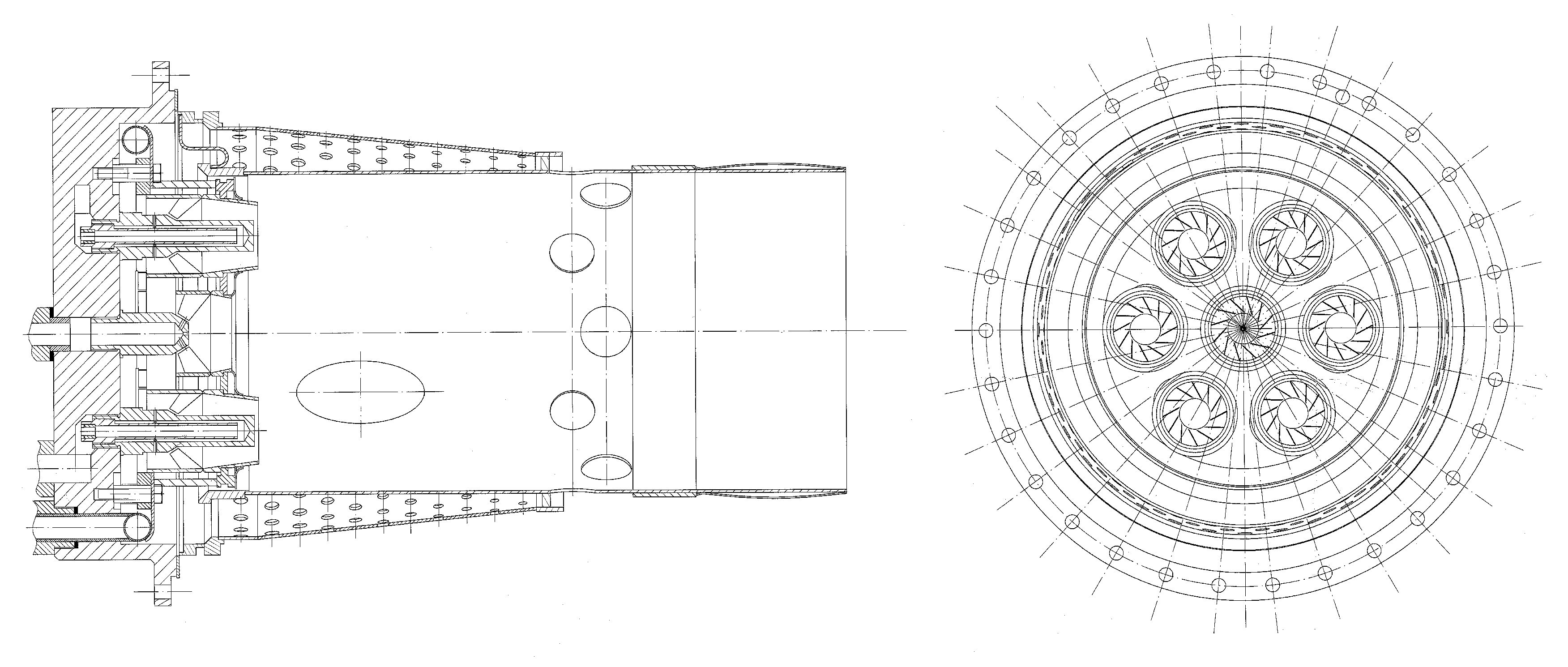
2.4. Analysis of the Design Features of the Combustion Chamber of Gas-Turbine Unit Type GT-009 M with Impact Cooling of the Burner Pipe

Rationality of the combustion chamber design is determined by how successfully organized the stable and pulse-free combustion of fuel at high combustion completeness is, a small loss of full head, and uniform gas temperature at the gas turbine inlet with limited overall dimensions and mass of the combustion chamber components, as well as ensuring the required reliability and durability of their work. Practical achievements in creating modern combustion chamber designs are largely determined by the results of research and experience obtained by teams of the largest domestic and foreign research facilities, institutes, and turbine building plants.
The designed version of the combustion chamber for GT-009 M of the block-section type consists of eight flame tubes arranged at an angle of 18° to the axis of the turbine in a common casing. The design of the combustion chamber makes it possible to dismantle the burner fronts and flame tubes without breaking open the turbine.
The flame tube consists of a cylindrical tube and a screen formed by two conical shells with an inner smaller Ø 225 mm. The lengths of the ferrules are 360 mm and 180 mm, and the length of the tube is 442 mm. The total length of the flame tube is 478 mm. There are 36 Ø 10 mm holes on the first ferrule and 72 Ø 10, Ø 9, Ø 8, Ø 7, and Ø 6 mm holes each on the cone. This combined hole system provides effective cooling of the flame tube metal.
The mixer has eight holes Ø 40 mm. At the end of the flame tube there is a collet seal of the coupling unit with a transition nozzle. The burner front is located on a flat perforated plate installed in the head part of the flame tube and sealed by a floating piston ring. The seven-burner front is formed by six flat conical swirlers Ø 52 mm at the inlet and Ø 46 mm at the outlet, the axes of which are parallel to the flame tube axis and 70 mm away from it, and a similar swirler located in the center of the front device. All swirlers have nozzles installed. In a number of experiments, a prechamber was installed on the central burner. The swirlers have 12 blades each, arranged at a 45° angle. There are 114 Ø 5 mm holes on the flat plate for cooling. In the center, the front device contains a flare-type igniter with a vortex system for stabilizing of preliminarily prepared depleted air–fuel mixture. Gas supply to the central and peripheral burners is separate. Each inlet is equipped with a valve for flow control.
The use of the block-section combustion chamber layout in the GT-009 M type gas turbine unit made it possible to test one flame tube of full-scale dimensions in bench conditions [12,13,14,15,16].
The use of heat-resistant, for example, composite ceramic, material also increases the longevity of the flame tube. In addition, there is an intermediate concentric cavity designed to collect the cooling air that has passed through the perforation of the outer wall and feed it into the combustion chamber of the flame tube, which ensures that all the air passing through the flame tube, including the air intended for cooling the walls of the flame tube, is used to prepare the air–fuel mixture and the formation of the combustion process. This increases the fuel efficiency of the gas turbine unit and reduces the emission of harmful substances in the exhaust gases.
Figure 1 shows a draft of a low-toxic combustion chamber of the gas turbine unit type GT-009 M.
Heat transfer in impact cooling of the combustion chamber flame tube depends on the numbers Re and Pr, the relative distance from the nozzle to the surface (h/d), the degree of turbulence of the jet, the shape and size of the nozzle, and the condition of its edge, as well as the geometric properties of the surface shape. A correlation formula is often used to calculate heat transfer in the frontal point area of a flat barrier:
Nu0 = C·Rem·Prn·(h/d)p,
where the coefficients C, m, n, and p vary widely among the authors [17,18,19,20,21]. This dependence leads to a monotonic increase in the number of Nu with increasing Re (m = 0.3–0.8), which is confirmed by experimental data [21,22].

3. Results

3.1. Analysis of the Results of the General Thermal Calculation of the Combustion Chamber

The calculation of the combustion chamber begins with the characteristics of the fuel, combustion products, and general balance. Thermal calculation is divided into general and zone calculation. The general calculation determines the characteristics of the combustion products behind the chamber, and in the zone calculation, in the sections along the length of the combustion zone [23].
The basic input data includes the following parameters:
  • Air flow rate for the combustion chamber—GA, kg/s.
  • Air pressure before the combustion chamber—pA, MPa.
  • Air temperature—TA, K.
  • Average temperature of combustion products behind the combustion chamber—T, K.
  • Type of fuel, its elementary composition.
  • Fuel temperature—TF, K.
  • Combustion efficiency factor (adopted)—ηC.
  • Steam or air temperature at fuel atomization—TS, K.
  • Relative flow rate of steam or air for fuel atomization—gS, kg/kg.
When performing the zone calculation, the first approximation of the combustion efficiency ηC and the excess air coefficients αi in the sections along the length of the combustion chamber are set.
In addition, the losses of pressure in the combustion chamber can be set σ; sectional or volumetric heat capacity UF and UV; uneven temperature field ΔT; allowable metal temperature T [23,24,25,26,27,28].
The overall thermal calculation of the combustion chamber resulted in the following data for 100%, 50%, and 0% load.
Accordingly:
  • Oxygen content O2A = 23.2, %.
  • Net calorific value of fuel LHV = 50.0, MJ/kg.
  • Normal density of combustion products behind the combustion chamber ρ N C = 1.30, kg/m3.
From the analysis of the results:
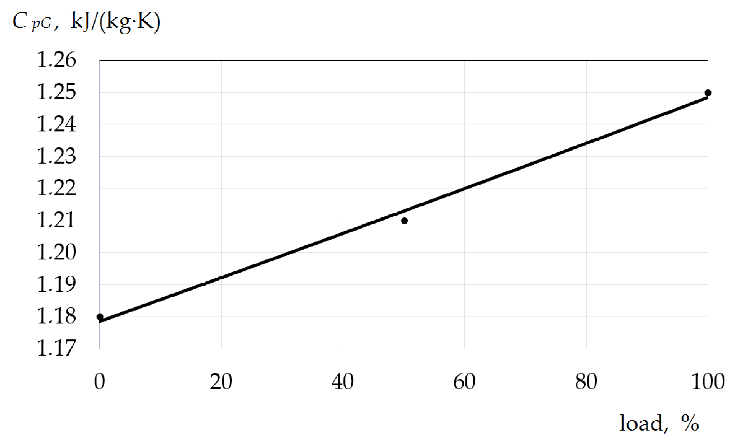
  • Average mass heat capacity of gases at α = 1, CpG decreases from 1.25, kJ/(kg·K) at 100, % load to 1.18, kJ/(kg·K) at 0, % load (refer to Figure 2).
  • Excess air ratio behind the combustion chamber α increases from 5.31 at 100% load to 12.7 at 0% load (refer to Figure 3).
  • Combustion products density behind the combustion chamber ρ C increases from 1.97 kg/m3 at 100% load to 2.48 kg/m3 at 0% load (refer to Figure 4).
  • Air density at the combustion chamber inlet ρ A increases from 3.13 kg/m3 at 100% load to 3.51 kg/m3 at 0% load (refer to Figure 5).
  • Total amount of gases at αs  L T increases from 91.8 kg/kg at 100% load to 218 kg/kg at 0% load (refer to Figure 6).
  • Mass fraction of triatomic gases rRO2 decreases from 0.0294 at 100% load to 0.0123 at 0% load (refer to Figure 7).
  • Mass fraction of water vapor rH2O decreases from 0.0267 at 100% load to 0.0112 at 0% load (refer to Figure 8).
As a result of the zone calculation, the main parameters along the path characterizing the thermal state of the flame tube of the combustion chamber were determined. The calculation was carried out taking into account the nominal load level corresponding to the maximum thermal stress.
Thermal zone calculation shows that the use of an impact system allows the effective cooling of the flame tube without exceeding the temperatures in the calculated zones, with respect to the allowable ones.

3.2. Analysis of the Results of Structural Calculation of the Combustion Chamber

The calculation is performed to determine the geometric parameters of the combustion chamber and is subdivided into a verification and design calculation. The verification calculation is performed for known or predetermined geometric characteristics of the combustion chamber and determines the forcing of the combustion process UF, primary air excess αΠ, and average air velocity along the tracts ωB [23,25,29,30,31,32,33,34].
The structural calculation of the combustion chamber resulted in the following data for 100%, 50%, and 0% load.
Accordingly:
  • Flame tube area FFT = 0.0397, m2.
  • Relative length of the flame tube LR = 2.4.
  • Area of registers at the outlet for one combustion chamber FR = 0.0126, m2.
  • Area of afterburning holes for one combustion chamber FA = 0.00224, m2.
  • Primary air path area for one combustion chamber FP = 0.0148, m2.
  • Area of one cooling band for one combustion chamber FC = 0.0127, m2.
  • Ring channel area for one combustion chamber FRC = 0.0147, m2.
  • Mixer area for one combustion chamber FM = 0.01, m2.
  • Air flow rate in the circular duct GCD = 24.1, kg/s.
From the analysis of the results:
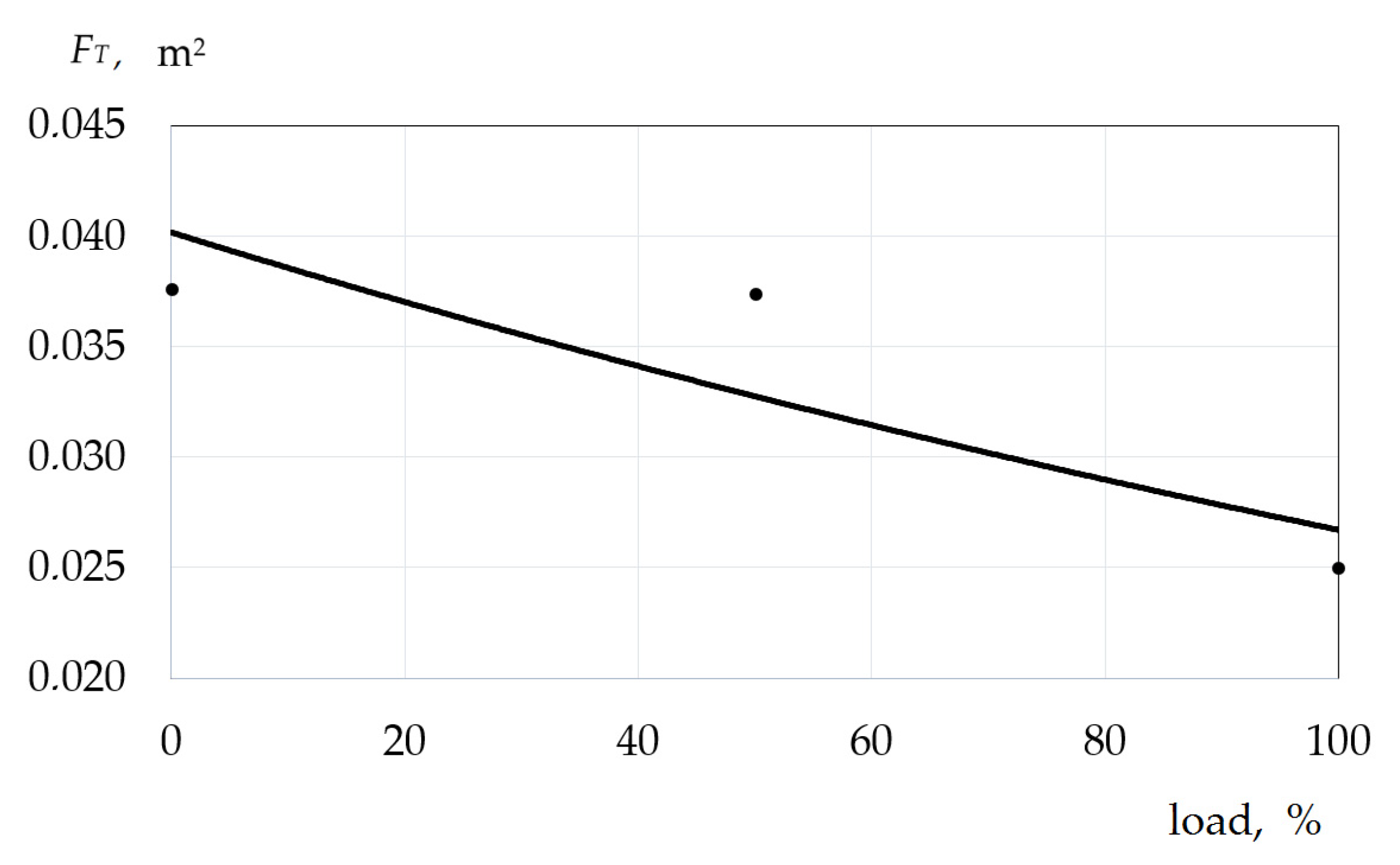
  • Total throughput area by the tracts of one combustion chamber FT increases from 0.0250 m2 at 100% load to 0.0376 m2 at 0% load (refer to Figure 9).
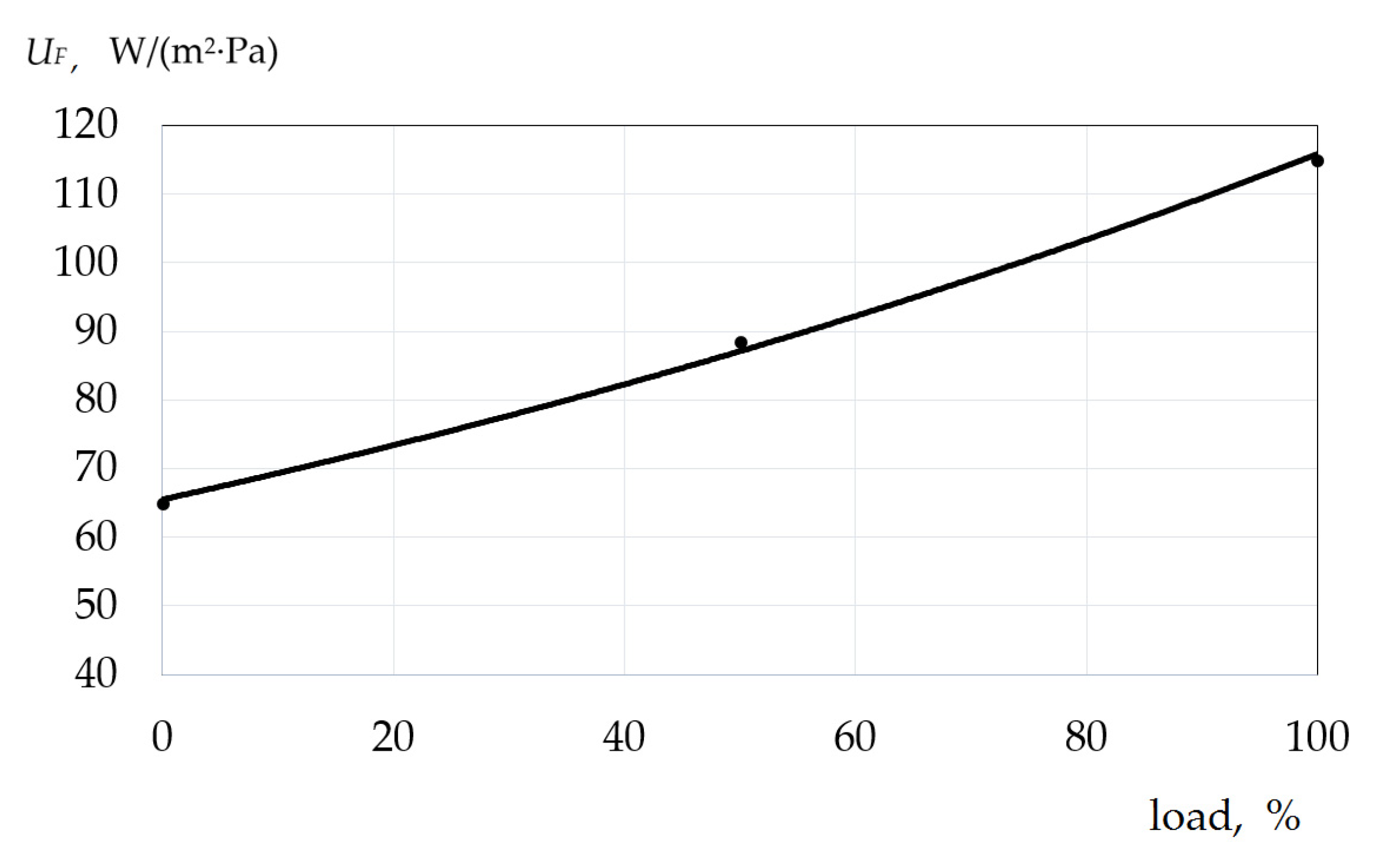
  • Forcing the combustion chamber UF decreases from 115.0 W/(m2·Pa) at 100% load to 65.0 W/(m2·Pa) at 0% load (refer to Figure 10).
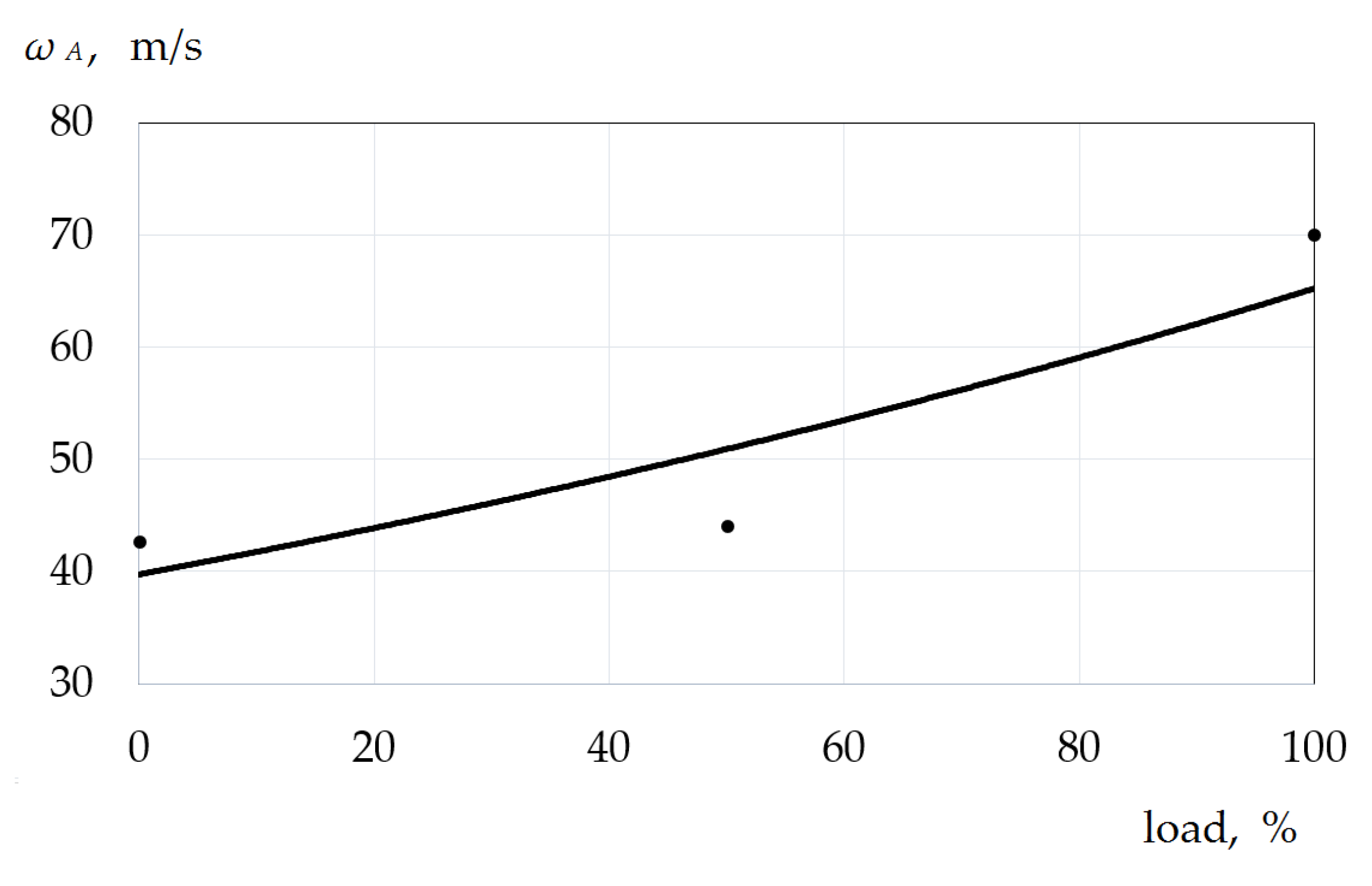
  • Average air velocity along the tracts ωA decreases from 70.1 m/s at 100% load to 42.7 m/s at 0% load (refer to Figure 11).
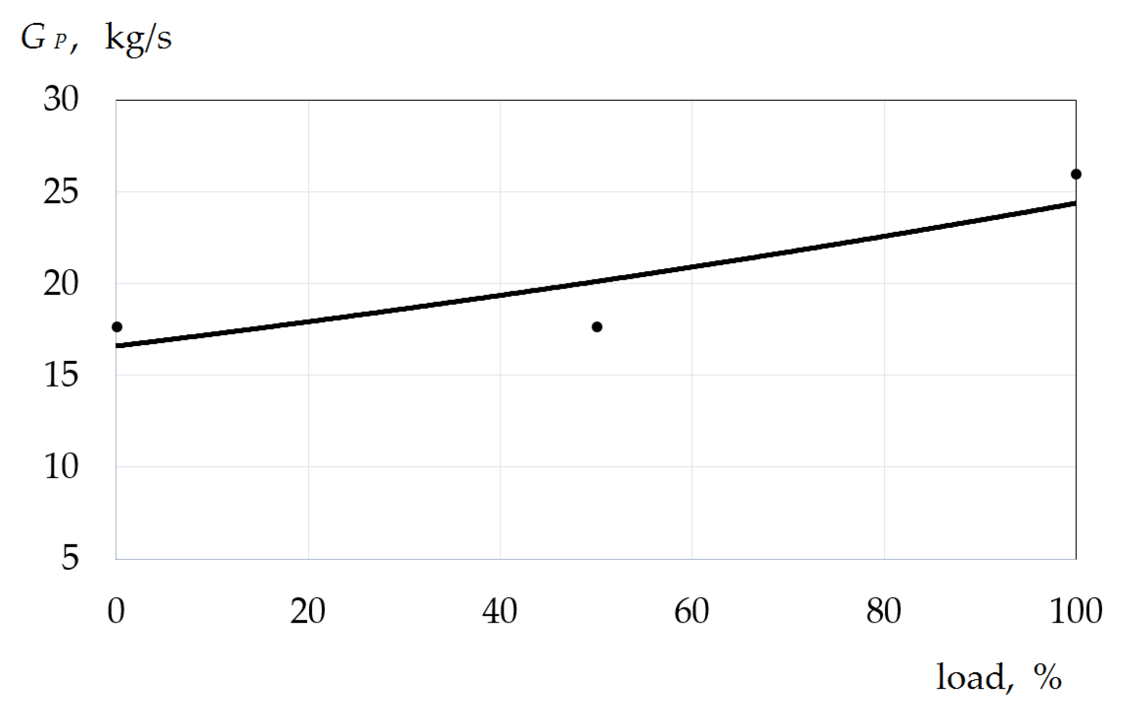
  • Primary air flow rate for all combustion chambers GP decreases from 26.0 kg/s at 100% load to 17.7 kg/s at 0% load (refer to Figure 12).
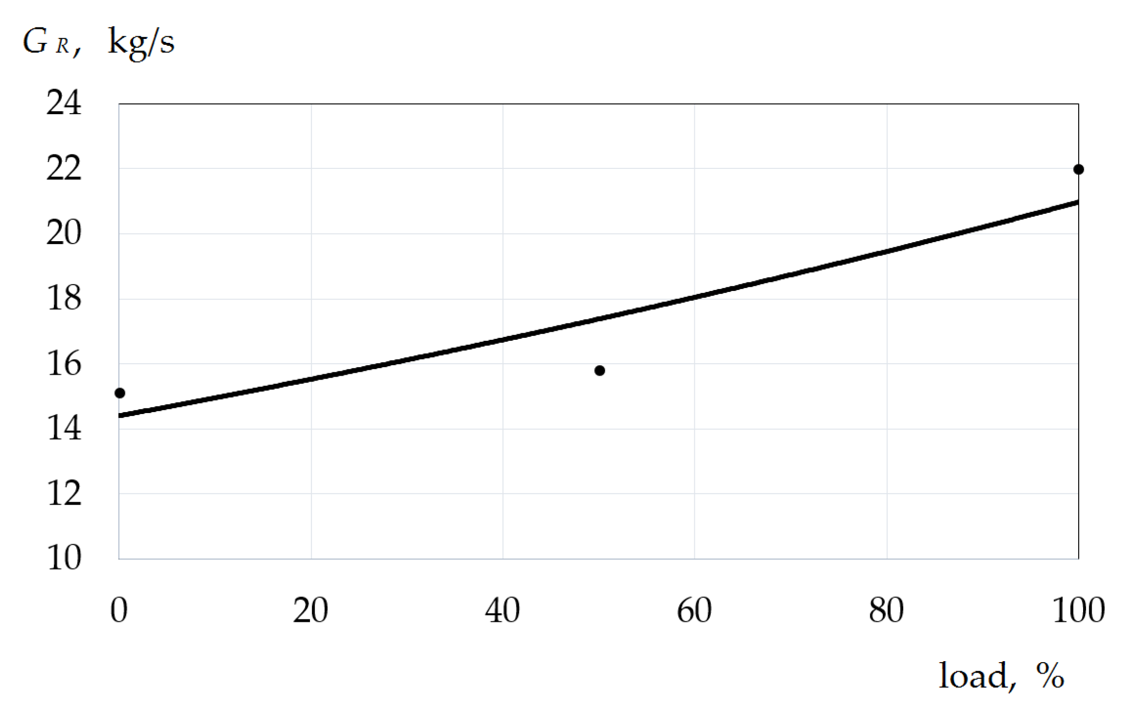
  • Air flow rate to registers for all combustion chambers GR decreases from 22.0 kg/s at 100% load to 15.1 kg/s at 0% load (refer to Figure 13).
  • Afterburning air consumption for all combustion chambers GAFT decreases from 3.93 kg/s at 100% load to 2.68 kg/s at 0% load (refer to Figure 14).
  • Mixing air flow rate for all combustion chambers GM decreases from 17.6 kg/s at 100% load to 12.0 kg/s at 0% load (refer to Figure 15).
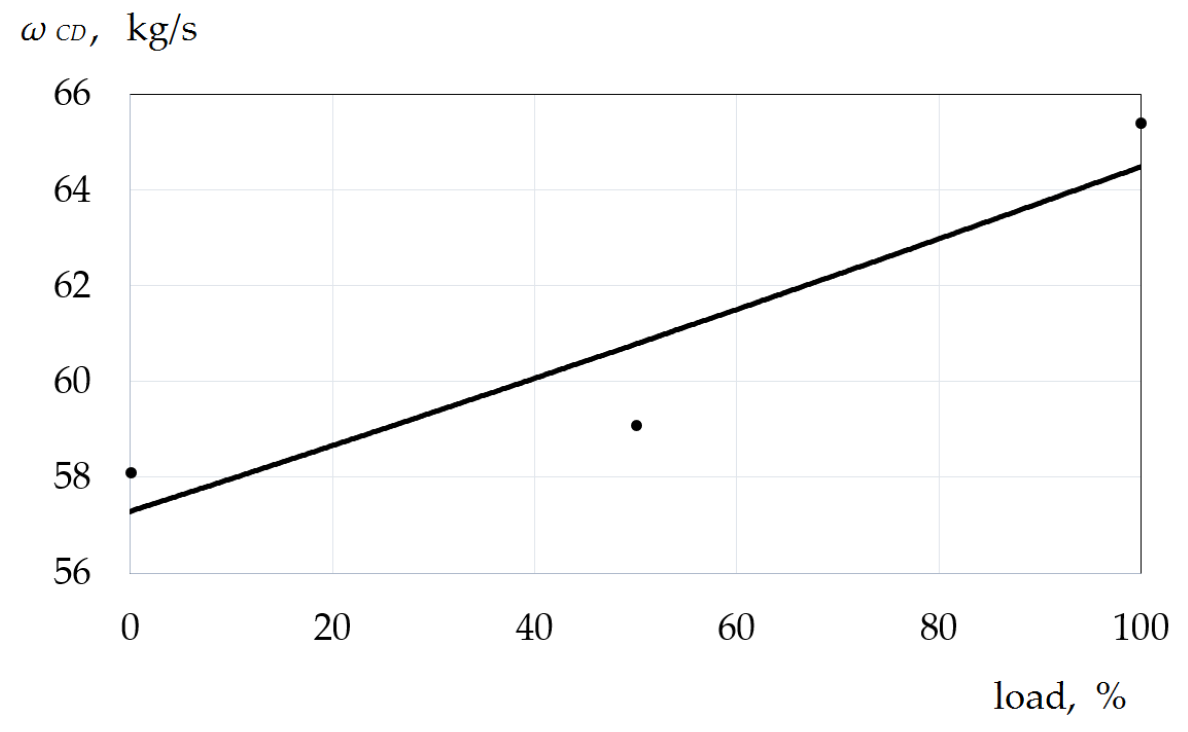
  • Air velocity in the circular duct ωCD decreases from 65.4 kg/s at 100% load to 58.1 kg/s at 0% load (refer to Figure 16).
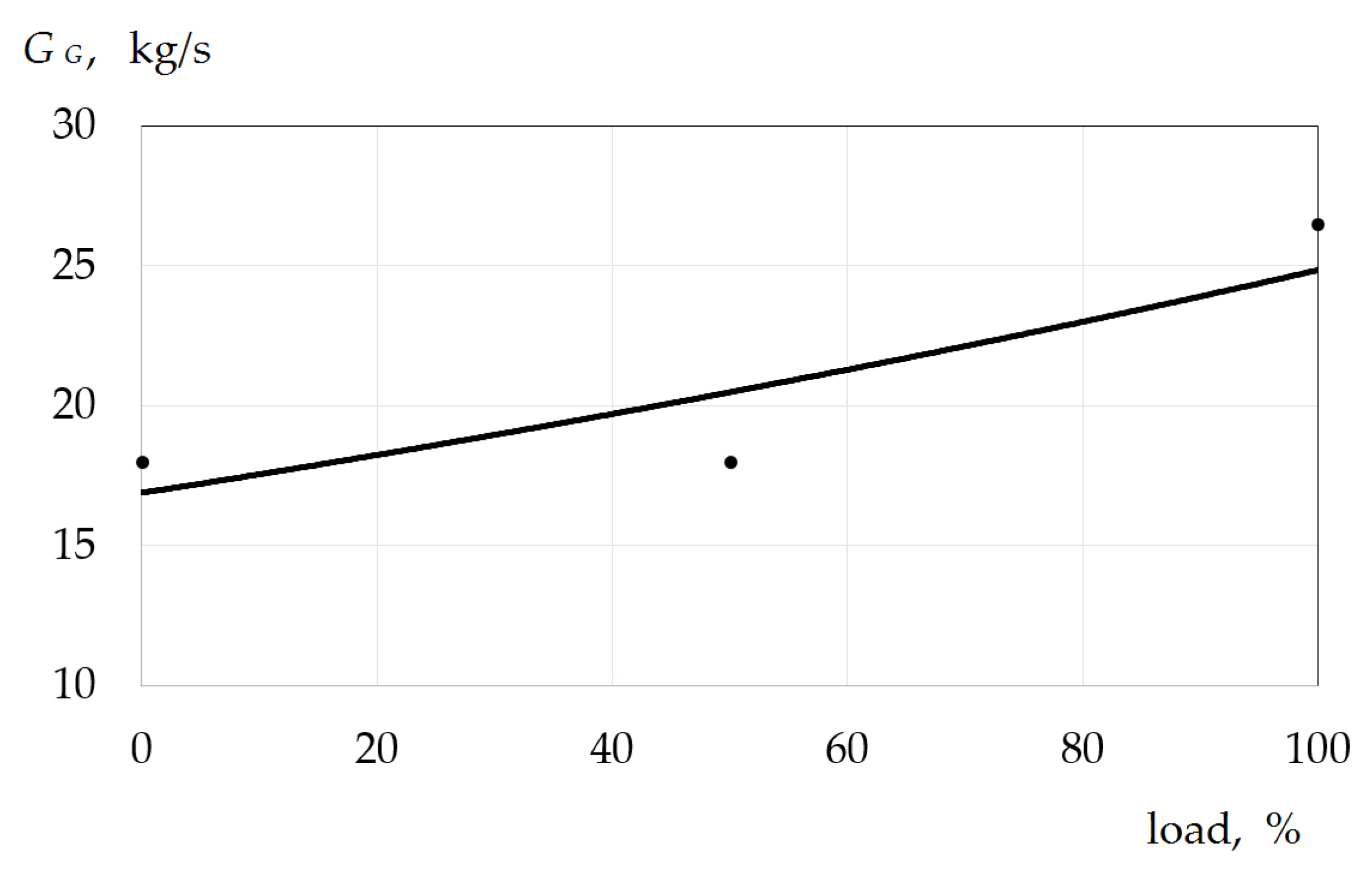
  • Gas flow in the combustion zone GG decreases from 26.5 kg/s at 100% load to 18.0 kg/s at 0% load (refer to Figure 17).
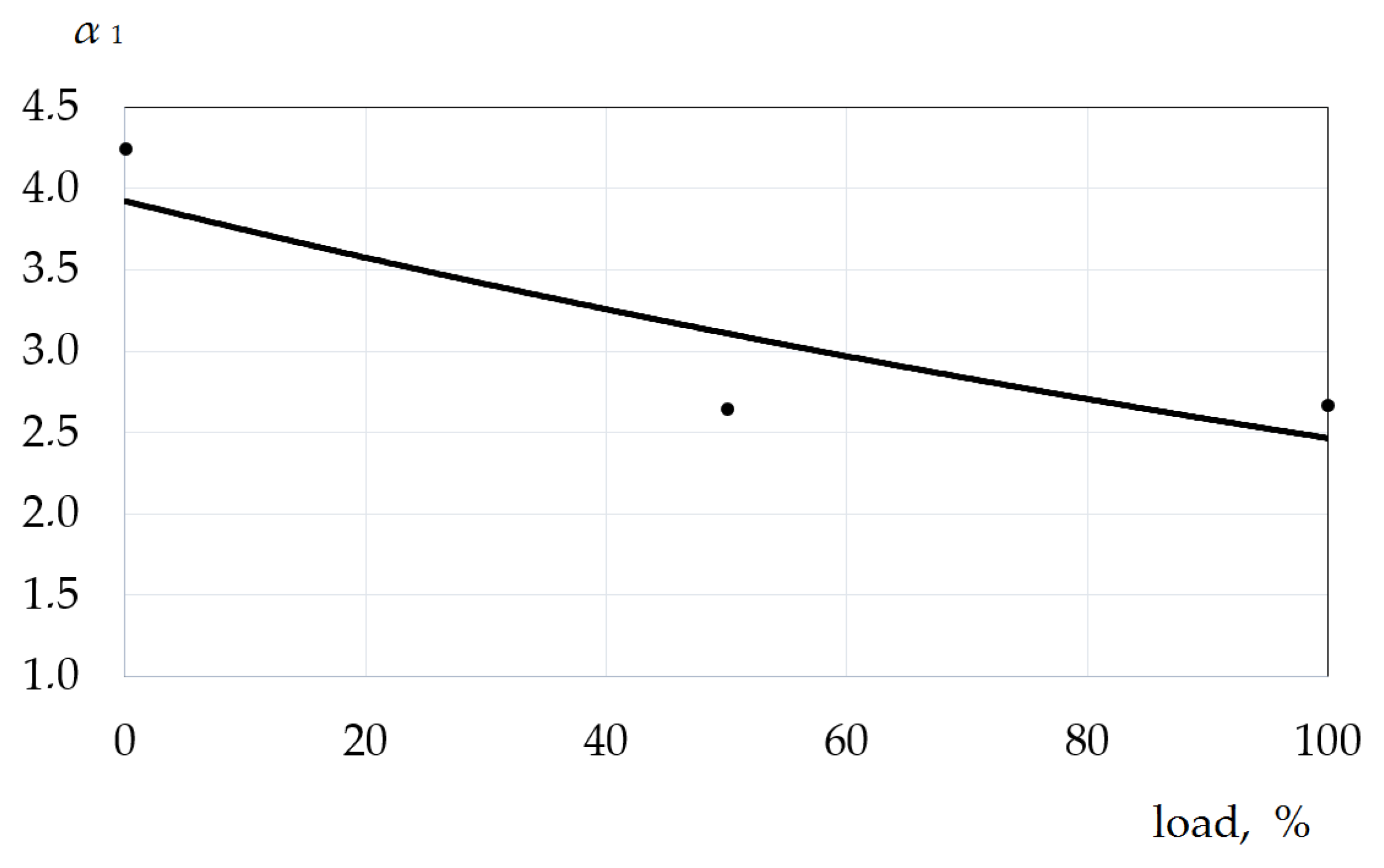
  • Surplus primary air α1 increases from 2.67 at 100% load to 4.25 at 0% load (refer to Figure 18).
  • Surplus secondary air α2 increases from 3.14 at 100% load to 5.01 at 0% load (refer to Figure 19).
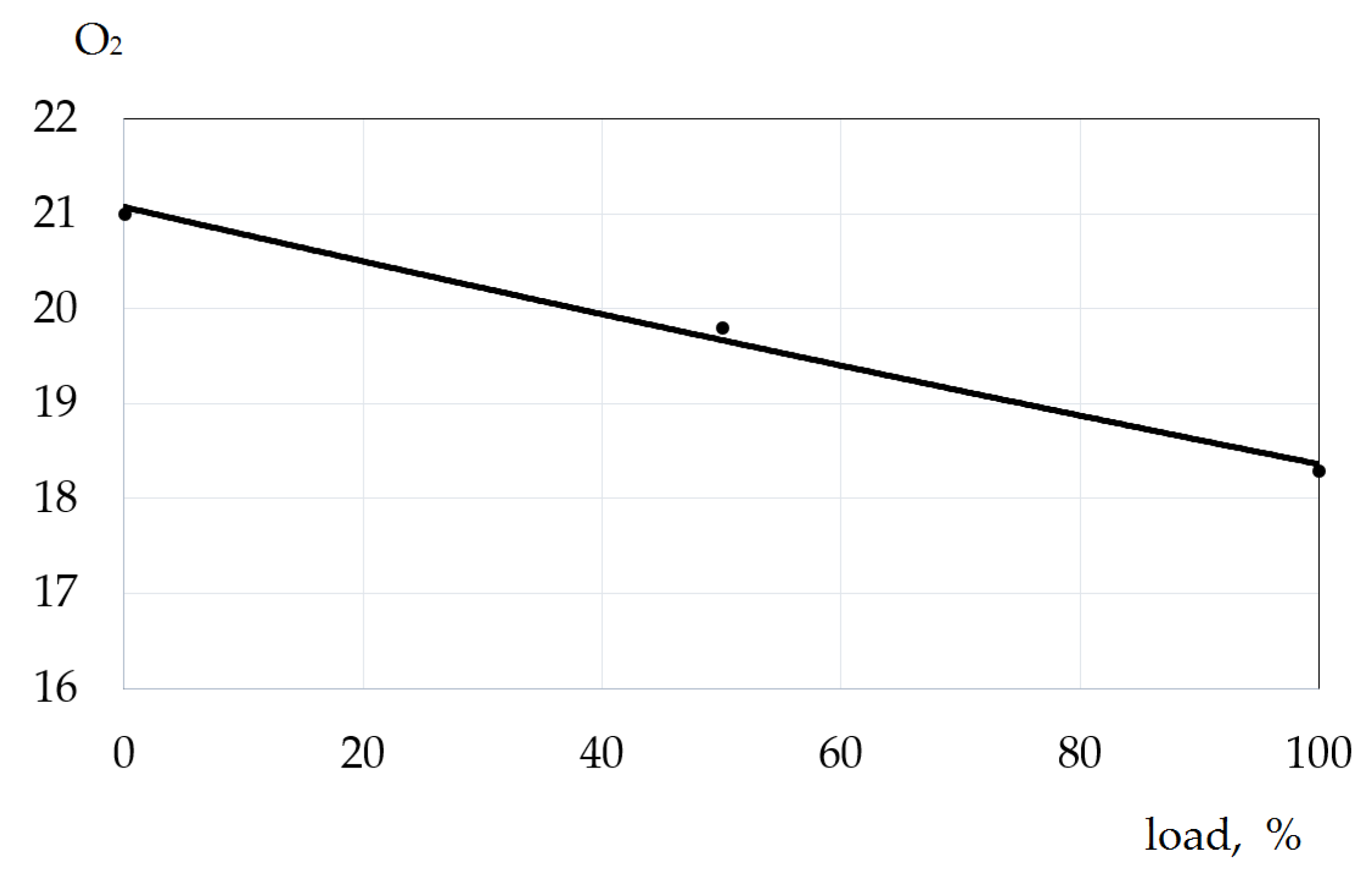
  • Oxygen content in combustion products O2 increases from 18.3% at 100% load to 21.0% at 0% load (refer to Figure 20).

4. Discussion

The decision on the expediency of creation and implementation of the combustion chamber of the gas turbine unit of GT-009 M type is made on the basis of the analysis of the economic effect determined for the annual volume of production of new equipment in the design year. The presence of economic effect indicates the feasibility of using new equipment.
The calculation of the economic effect is based on the reduction of NOx emissions of the experimental combustion chamber stand, as well as the changes in the design of the flame tube cooling.
Number of operating hours of the unit per year:
r = B·C = 365 × 16 = 5840 h,
where B—number of days per year, B = 365 d; C—number of operating hours of the unit per year, C = 16 h.
Number of emissions per year:
B Y = ( G A + G G ) × 3600 × τ ρ = ( 138 + 3.49 ) × 3600 × 5840 1.31 = 2.27 × 10 9   m 3 / y ,
where GA—air flow rate, GA = 138 kg/s; GG—total fuel consumption, GG = 3.49 kg/s; τ—time, τ = 5840 s; ρ—normal flue gas density, ρ = 1.31 kg/m3.
At the base concentration of nitrogen oxides N31 = 200 mg/m3, emission NOx equals:
m1 = BY·N31 10−6 = 2.27 × 109 × 200 × 10−6 = 454,000 kg/y = 454 t/y.
Emission of the projected plant N15 = 50 mg/m3,
m2 = m1·N15/N31 = 454 × 50/200 = 113.5 t/y,
M = A·m1 = 41.1 × 454 = 18,659.4, refer. t/y,
where m—annual emission NOx into the atmosphere, t/y; A—aggressiveness index NOx, A = 41.1 spec. t/y.
Annual economic damage at a typical plant:
y1 = γ·G·f·M = 40 × 4 × 0.09 × 18,659.4 = USD 268,695.4/y;
y1 = USD 26.87 million/y,
where γ—specific damage, i.e., damage caused by one ton of monopollutant emitted into the atmosphere, γ = USD 40/refer. t; G—value, the value of which is determined in accordance with the table of methods, in our case, G = 4, i.e., for areas of industrial enterprises; f—the size of the ascent of the emission torch in the atmosphere, f = 0.09.
Reduction of the reduced mass of the annual emission NOx at the expense of events:
ΔM = (m1m2A = (454 − 113.5) × 41.1 = 13,994.55 refer. t/y.
Annual economic damage at the projected plant:
y2 = γ·G·f·ΔM = 40 × 4 × 0.09 × 13,994.55 = USD 201,521.5/y;
y2 = USD 20.15 million/y.
Economic effect of the modernized combustion chamber:
Δy = y1y2 = 26.87 − 20.15 = USD 6.72 million/y.
The economic effect from the implementation of the designed combustion chamber due to the reduction of emissions of harmful substances is USD 6.72 million/y.
In various regions of Europe, the United States, and the Russian Federation, the growth of environmental security is occurring against a background of increasing levels of socioeconomic development. At the same time, an increase in the number of objects polluting the environment is usually accompanied by a decrease in the volume of emissions of pollutants into the atmosphere [3,35,36,37,38].
Analysis of a low-toxic combustion chamber of the GT-009 M type gas turbine unit with flame tube impact cooling was performed. The high efficiency of the method of combustion of a preliminarily prepared depleted air–fuel mixture is shown. The performed technical and economic analysis confirms a sufficiently high efficiency of the implementation of this method of combustion of air–fuel mixture in combination with the impact cooling of the flame tube and the corresponding rational design of the combustion chamber. The analysis can be an incentive for active participation of researchers in international projects.

Author Contributions

Conceptualization, S.M. (Sergej Maspanov), A.S. and I.B.; methodology, S.M. (Sergej Maspanov) and A.S.; software, A.S.; validation, A.S., I.B. and V.S.; formal analysis, S.M. (Sergej Maspanov) and A.S.; investigation, S.M. (Sergej Maspanov), I.B., S.M. (Svetlana Martynenko), and V.S.; resources, S.M. (Sergej Maspanov) and V.S.; data curation, S.M. (Sergej Maspanov); writing—original draft preparation, S.M. (Sergej Maspanov); writing—and editing, A.S. and I.B.; visualization, S.M. (Svetlana Martynenko) and V.S.; supervision, A.S.; project administration, S.M. (Sergej Maspanov) and A.S. All authors have read and agreed to the published version of the manuscript.

Funding

This research was carried out by Peter the Great St. Petersburg Polytechnic University and supported under the strategic academic leadership program «Priority 2030» of the Russian Federation (Agreement 075-15-2021-1333 dated 30 September 2021).

Institutional Review Board Statement

Not applicable.

Informed Consent Statement

Not applicable.

Data Availability Statement

Not applicable.

Conflicts of Interest

The authors declare no conflict of interest.

References

  1. Lefebvre, A.; Ballal, D. Gas Turbine Combustion Alternative Fuels and Emissions, 3rd ed.; CRC Press: Boca Raton, FL, USA, 2010; p. 558. [Google Scholar]
  2. Smirnov, A. Snizhenie Vrednyh Vybrosov v Kamerah Sgoraniya Moshchnyh Energeticheskih GTU na baze Raschetnyh i Eksperimental’nyh Issledovanij. Ph.D. Thesis, St. Petersburg Institute VTUZ-LMZ, St. Petersburg, Russia, 2000. [Google Scholar]
  3. Roslyakov, P.; Kondrat’eva, O. Razrabotka normativnogo dokumenta na proektirovanie i ekspluataciyu sistem nepreryvnogo kontrolya i ucheta vrednyh vybrosov TES. Ind. Power Eng. 2016, 8, 45–52. [Google Scholar]
  4. Canilo, P.; Podgorny, A.; Christich, V. Energeticheskie i Ekologicheskie Harakteristiki GTD pri Ispol’zovanii Uglevodorodnyh Topliv i Vodoroda; Naukova Dumka: Kiev, Ukraine, 1987; p. 221. [Google Scholar]
  5. Fenimore, C. Formation of nitric oxide from fuel nitrogen in ethylene flames. Combust. Flame 1972, 19, 289–296. [Google Scholar] [CrossRef]
  6. Mitrofanov, V.; Rudakov, O.; Sigalov, Y. A methodology for calculating unsteady combustion in a gas-turbine engine. Therm. Eng. 2005, 52, 874–878. [Google Scholar]
  7. Smirnov, A.; Tolmatchew, V. Sposoby stabilizacii processa goreniya predvaritel’no podgotovlennoj obednennoj toplivovozdushnoj smesi v KS GTU. Mod. Turbine Constr. 2000, 3, 86–90. [Google Scholar]
  8. Asoskov, V.; Shestakov, N.; Ogonykov, K.; Smirnov, A.; Chebakova, G. Combustion Chamber. Utility Model Patent RU 151885 U1, 20 April 2015. Available online: https://elibrary.ru/download/elibrary_38370290_74920632.pdf (accessed on 28 July 2021).
  9. Mitrofanov, V. Kameri Sgoraniya Gazoturbinnih Dvigatelei: Matematicheskoe Modelirovanie, Metodologiya Rascheta Koncepciya Optimalnogo Proektirovaniya. Ph.D. Thesis, St. Petersburg Polytechnic University, St. Petersburg, Russia, 2004. [Google Scholar]
  10. Schennikov, K.; Bogov, I.; Tolmatchew, V. Elektroiskrovye zapal’no-gorelochnye ustrojstva. Mod. Turbine Constr. 2000, 3, 68–85. [Google Scholar]
  11. Christich, V.; Shevchenko, A.; Ozerov, A.; Savchenko, V. Flame Tube of the Combustion Chamber of a Gas Turbine Engine. Utility Model Patent SU 1719800 A1, 15 March 1992. Available online: https://elibrary.ru/download/elibrary_40695648_16301705.pdf (accessed on 28 July 2021).
  12. Tolmatchew, V. Modelirovanie i Issledovanie Vihrevogo Zapalno-Stabiliziruyuschego Modulya kamer Sgoraniya Gazoturbinnih Ustanovok. Ph.D. Thesis, St. Petersburg Polytechnic University, St. Petersburg, Russia, 2012. [Google Scholar]
  13. Kuznetsov, E.; Snegirev, A.; Markus, E. Radiative Extinction of Laminar Diffusion Flame above the Flat Porous Burner in Microgravity: A Computational Study. Combust. Explos. Shock. Waves 2020, 56, 394–411. [Google Scholar] [CrossRef]
  14. Maspanov, S.; Bogov, I.; Sukhanov, V.; Tolmatchew, V. Ignition of the flame in the combustion chamber of a gas turbine for electric power generation. Energies 2022, in press.
  15. Mikhajlov, V.; Vertkin, M.; Kruglikov, P.; Smirnov, A.; Homenok, L. Gibridnye ugol’no-gazovye PGU bol’shoj moshchnosti: Osnovnye tekhnicheskie i skhemnye resheniya. Energetik 2013, 12, 7–10. [Google Scholar]
  16. Mikhajlov, V.; Vertkin, M.; Kruglikov, P.; Smirnov, A.; Homenok, L. Sbrosnye PGU s ugol’nymi paroturbinnymi blokami bol’shoj moshchnosti: Termodinamicheskij aspekt. Energetik 2014, 1, 11–14. [Google Scholar]
  17. Lemanov, V.; Terekhov, V.; Terekhov, V. Teploobmen v impaktnoj osesimmetrichnoj strue. In Sekciya №1 Turbulentnye Techeniya v Odnofaznyh sredah, Intensifikaciya Teploobmena, Proceedings of the Vserossijskaya konferenciya «XXXV Sibirskij Teplofizicheskij Seminar», Novosibirsk, Russia, 27–29 August 2019; Pahomov, M., Bogatko, T., Eds.; Izd-vo Srochnaya Poligrafiya: Novosibirsk, Russia, 2019; p. 33. [Google Scholar]
  18. Tumanovskii, A.; Bulysova, L.; Vasil’ev, V.; Gutnik, M.; Gutnik, M. Development of Low-Emission Combustors for Power-Generating GTUs. Therm. Eng. 2021, 68, 473–480. [Google Scholar] [CrossRef]
  19. Breus, V.; Shestakov, N.; Leikam, A.; Smirnov, A.; Andrienko, V. Organizaciya szhiganiya vodougol’nyh toplivnyh suspenzij v tekhnologicheskoj kamere sgoraniya. Mod. Sci. Res. Ideas Results Technol. 2012, 3, 3–7. [Google Scholar]
  20. Sergeev, V.; Anikina, I.; Kalmykov, K. Using Heat Pumps to Improve the Efficiency of Combined-Cycle Gas Turbines. Energies 2021, 14, 2685. [Google Scholar] [CrossRef]
  21. Snegirev, A.; Markus, E.; Kuznetsov, E.; Harris, J.; Wu, T. On soot and radiation modeling in buoyant turbulent diffusion flames. Heat Mass Transf./Waerme-Stoffuebertragung 2018, 54, 2275–2293. [Google Scholar] [CrossRef]
  22. Bogov, I.; Kulandin, A.; Sukhanov, V.; Tolmatchew, V.; Bezukhov, A.; Smirnov, A.; Bodrov, A.; Korihin, N. Fundamentals of Technical Thermodynamics, Thermochemistry, and Cycle Analysis of Gas-Turbine Plants; IA Energomashinostroenie: St. Petersburg, Russia, 2007; p. 192. [Google Scholar]
  23. Asoskov, V.; Denezhkin, L.; Smirnov, A.; Tolmatchew, V. Razrabotka konstrukcij malotoksichnyh kamer sgoraniya dlya energeticheskih GTU. In Proceedings of the XLIV Nauchno-Tekhnicheskaya Sessiya po Problemam Gazovyh Turbin, St. Petersburg, Russia, 16–17 September 1997; OAO «VTI» Press: St. Petersburg, Russia, 1997; pp. 43–45. [Google Scholar]
  24. Arseniev, L.; Tyryshkin, V.; Bogov, I.; Podobuyev, Y.; Levin, Y. Stationary Gas Turbine Units; Mashinostroenie: St. Petersburg, Russia, 1989; p. 543. [Google Scholar]
  25. Bulysova, L.; Vasil’ev, V.; Gutnik, M.; Pugach, K. Razvitie maloemissionnyh kamer sgoraniya dlya perspektivnyh GTU. In Sekciya №1 Rabochij Process kamer sgoraniya GTD i GTU, Proceedings of the Processy Goreniya, Teploobmena i Ekologii Teplovyh Dvigatelej, Sbornik Tezisov XI Vserossijskoj Nauchno-Tekhnicheskoj Konferencii s Mezhdunarodnym Uchastiem, Samara, Russia, 26–27 September 2019; Lukachyov, S., Ed.; Samara University Press: Samara, Russia, 2019; pp. 7–8. [Google Scholar]
  26. Maspanov, S.; Bogov, I.; Tolmatchew, V.; Rassokhin, V. Methodology of engineering and design calculation of swirl burner systems of combustion chambers based on VZGM. In Turbines, Hydraulic Machines and Aircraft Engines, Proceedings of the XLIV SPbPU Science Week: Scientific Forum with International Participation. Institute of Energy and Transport Systems, St. Petersburg, Russia, 30 November–5 December 2015; Polytechnic University Press: St. Petersburg, Russia, 2015; pp. 49–51. [Google Scholar]
  27. Maspanov, S.; Bogov, I.; Sukhanov, V. Experimental research in possibilities of quality improvement of burning processes in burners of turbines. In Sekciya «Energeticheskoe Mashinostroenie», Proceedings of the Scientific Conference with International Participation «Week of Science 2019», St. Petersburg, Russia, 18–23 November 2019; Plotnikov, A., Ed.; Politekh Press: St. Petersburg, Russia, 2019; pp. 289–291. [Google Scholar]
  28. Xia, C.; Brindhadevi, K.; Elfasakhany, A.; Alsehli, M.; Tola, S. Numerical modelling of the premixed compression ignition engine for superior combustion and emission characteristics. Fuel 2021, 306, 121540. [Google Scholar] [CrossRef]
  29. Bulysova, L.; Vasil’ev, V.; Berne, A.; Gutnik, M. Experience gained from construction of low-emission combustion chambers for on-land large-capacity gas-turbine units: GT24/26. Therm. Eng. 2018, 65, 362–370. [Google Scholar] [CrossRef]
  30. Bulysova, L.; Gutnik, M.; Pugach, K. Snizhenie emissii NOx putem organizacii posledovatel’nogo dvuhstupenchatogo szhiganiya topliva. Gazoturbinnye Tekhnologii 2020, 2, 24–27. [Google Scholar]
  31. Maspanov, S.; Bogov, I.; Tolmatchew, V.; Sukhanov, V. Stand for Studying the Effect of Ozone on the Processes in the Combustion Chamber of a Gas Turbine Unit. Utility Model Patent RU 175593 U1, 10 March 2017. Available online: https://elibrary.ru/download/elibrary_38300204_54509408.pdf (accessed on 28 July 2021).
  32. Tsybizov, Y.; Tyulkin, D.; Vorotyntsev, I. Technology of low-emission fuel combustion and conceptual structure of the combustion chamber of a gas-turbine power plant. Vestn. Samara Univ. Aerosp. Mech. Eng. 2020, 19, 107–120. [Google Scholar] [CrossRef]
  33. Maspanov, S.; Bogov, I.; Sukhanov, V. Oxidizer ozonation as a method of fuel combustion intensification at thermal power facilities. In Turbines, Hydraulic Machines and Aircraft Engines, Proceedings of the XLVI SPbPU Science Week, Institute of Energy and Transport Systems, St. Petersburg, Russia, 13–19 November 2017; Polytechnic University Press: St. Petersburg, Russia, 2017; pp. 114–116. [Google Scholar]
  34. Maspanov, S.; Bogov, I.; Sukhanov, V. Experimental study of the effect of ozone on nitrogen dioxide emissions during combustion of gaseous fuel in a swirl ignition burner module. In Turbines, Hydraulic Machines and Aircraft Engines, Proceedings of the XLVI SPbPU Science Week, Institute of Energy and Transport Systems, St. Petersburg, Russia, 13–19 November 2017; Polytechnic University Press: St. Petersburg, Russia, 2017; pp. 116–119. [Google Scholar]
  35. Demidova, S.; Balog, M.; Chircova, T.; Kulachinskaya, A.; Zueva, S.; Akhmetova, I.; Ilyashenko, S. Development of methodology and assessment of ecological safety of the EAEU and CIS regions in the context of sustainable development. Economies 2021, 9, 100. [Google Scholar] [CrossRef]
  36. Roslyakov, P.; Khokhlov, D.; Proskurin, Y. Development of combined low-emissions burner devices for low-power boilers. Therm. Eng. 2017, 64, 574–584. [Google Scholar] [CrossRef]
  37. Kawahara, H.; Furukawa, K.; Ogata, K.; Mitani, E.; Mitani, K. Experimental study on the stabilization mechanism of diffusion flames in a curved impinging spray combustion field in a narrow region. Energies 2021, 14, 7171. [Google Scholar] [CrossRef]
  38. Wei, Z.; Wang, L.; Liu, H.; Liu, Z.; Zhen, H. Numerical investigation on the flame structure and CO/NO formations of the laminar premixed biogas–hydrogen impinging flame in the wall vicinity. Energies 2021, 14, 7308. [Google Scholar] [CrossRef]
Figure 1. Draft of a low-toxic combustion chamber of the gas turbine unit type GT-009 M.
Energies 15 00707 g001
Figure 2. Dependence of the average mass heat capacity of gases at α = 1 on the load value.
Energies 15 00707 g002
Figure 3. Dependence of the excess air ratio behind the combustion chamber on the load value.
Energies 15 00707 g003
Figure 4. Dependence of the density of combustion products behind the combustion chamber on the load value.
Energies 15 00707 g004
Figure 5. Dependence of air density at the combustion chamber inlet on the load value.
Energies 15 00707 g005
Figure 6. Dependence of the total amount of gases at αs on the load value.
Energies 15 00707 g006
Figure 7. Dependence of mass fraction of triatomic gases on the load value.
Energies 15 00707 g007
Figure 8. Dependence of mass fraction of water vapor on the load value.
Energies 15 00707 g008
Figure 9. Dependence of the total throughput area along the tracts of one combustion chamber on the load value.
Energies 15 00707 g009
Figure 10. Dependence of combustion chamber forcing on the load value.
Energies 15 00707 g010
Figure 11. Dependence of average air velocity along the tracts on the load value.
Energies 15 00707 g011
Figure 12. Dependence of primary air flow rate for all combustion chambers on the load value.
Energies 15 00707 g012
Figure 13. Dependence of air flow rate to registers for all combustion chambers on the load value.
Energies 15 00707 g013
Figure 14. Dependence of afterburning air consumption for all combustion chambers on the load value.
Energies 15 00707 g014
Figure 15. Dependence of mixing air flow rate for all combustion chambers on the load value.
Energies 15 00707 g015
Figure 16. Dependence of air velocity in the circular duct on the load value.
Energies 15 00707 g016
Figure 17. Dependence of gas flow rate in the combustion zone on the load value.
Energies 15 00707 g017
Figure 18. Dependence of surplus primary air on the load value.
Energies 15 00707 g018
Figure 19. Dependence of surplus secondary air on the load value.
Energies 15 00707 g019
Figure 20. Dependence of oxygen content in combustion products on the load value.
Energies 15 00707 g020
Publisher’s Note: MDPI stays neutral with regard to jurisdictional claims in published maps and institutional affiliations.

