1. Introduction
One of the applications for which PV generators are considered highly adequate is water pumping systems [
1,
2,
3,
4]. In many of these systems the operation is compatible with the intermittency of the electrical energy supplied by the generators. Therefore, it is possible to implement a completely renewable and clean solution that does not produce greenhouse gases. On the other hand, it is extremely important and appropriate to implement it in rural and remote areas [
4,
5,
6]. Taking these factors into consideration, the development of a reliable and economical pumping system is fundamental.
One of the aspects that must be considered in a pumping system is the choice of the electric motor. Several types of motor can be used in this type of application [
6]. However, one of the motors that is considered the most interesting is the switching reluctance machine (SRM). When compared to other industrial motors, this motor is considered simple in design [
7]. As a consequence, several applications and research studies have been performed [
8,
9,
10,
11,
12]. From these applications and studies, it was possible to verify that in fact, the SRM showed excellent characteristics for this kind of application.
One fundamental aspect of the application of an SRM is the electronic power converter that must be used to operate the motor; several topologies can be adopted. The classic solution is the asymmetrical half-bridge topology [
13,
14,
15]. However, many other two-level topologies have been presented and proposed. Most of those topologies are characterized to reduce the number of electronic power components [
16,
17,
18,
19,
20]. However, electronic power converters are prone to faults in their switches [
21]. Thus, in order to consider this aspect, several topologies have been developed with the purpose of providing fault-tolerant capability for this type of faults. The approach to developing these converters is based on the introduction of extra switches and/or relays. An example in which an extra leg and relays to connect it to the faulty phase are introduced can be seen in [
22]. Another topology that introduces new switches and relays was also proposed in [
23]. In this topology, instead of using a leg with a switch and a diode, a classical leg with two switches and two diodes is used. One interesting concept that is used in the context of this topology is that in fault-tolerant mode, changes in the current excitation are also considered. Another topology in which extra switches were introduced, but with the purpose of minimizing them, is presented in [
24]. A fault-tolerant system with extra switches and windings (dual-channel switched reluctance motor) was also proposed by [
25]. It is characterized by two operational models. The first operational model works like a three-phase conventional SRM delivered by an H-bridge inverter, driven by square-wave currents. The second operational model involves two SRMs, mutually coupled, being supplied by sine-wave currents. These operational models are used to solve various faults, and the corresponding remedial current strategies are proposed to perform fault-tolerant operation. In [
26], another topology was proposed with extra switches that can be arranged to work in the usual and modular driving modes so that the advantages of both driving methods can be applied. A topology with two additional switches and six thyristors, complementing the classical AHB, was also proposed [
27]. In [
28], a topology that uses a standby single-phase full bridge in combination with an extra group of mechanical switches replacing up to four faulty active switches was presented. However, this solution is not capable of isolating short-circuit failures in controlled-power semiconductors. The fault-tolerant solution presented in [
29] combines a classical AHB topology with a classical redundant VSI topology applied to a three-phase SRM. The redundant three-phase VSI is linked to every central-tapped winding phase. In [
30], a fault-tolerant topology with an additional classical single-phase full-bridge joined with six mechanical relays applied to a three-phase SRM was presented. Each phase of the converter is divided into three windings to connect additional controlled power semiconductors in fault-tolerant operation. In [
31], the use of two inverter legs for each phase for a special six-phase 12/8 SRM was proposed to increase drive system reliability, based on the concept of increasing the number of legs per phase of the inverter. This proposal uses a mutually coupled dual three-phase SRM.
Solutions in which only relays are used were also proposed [
32,
33]. The first solution benefits from the independence between SRM phases and demands static switches linked between phases that are not in sequence. The second solution uses the same principle presented in [
32] with some enhancements regarding fault-tolerant operation. This solution uses healthy legs to control two phases that are not in a sequence; for example, in a four-phase SRM, phases ‘A’ and ‘C’ or phases ‘B’ and ‘D’. It uses various changeover solid-state relays (SSRs) to link the faulty legs to other healthy phases, so as to replace and isolate the faulty devices. This solution offers the advantage of isolating faulty controlled power semiconductors regardless of the failure mode. Another category of power converter topology that can be used with the SRM features the ability to generate multilevel voltages. Consequently, it is possible to improve the performance of the machine and reduce the power semiconductors’ switching frequency [
34]. Another important aspect of multilevel topologies is that they can provide fault-tolerant capability. In this way, T-type and neutral point clamped asymmetric half-bridge (NPC) topologies have been studied [
34,
35,
36,
37,
38]. However, these topologies present some limitations regarding their fault-tolerant capability for all types of faults. Topologies based on the modular multilevel converter (MMC) were also proposed. One of the solutions is the classical asymmetric MMC [
34]. In this solution, the MMC’s structure is linked to the asymmetric bridge converter [
39]. In [
40], an NPC-AHB converter with intrinsic dc-link voltage boosting capacitors was presented. This topology was developed for an 8/6 SRM and characterized by two NPC-AHB converters, one of which was connected to phases A and C and the other to phases B and D. This converter was proposed for applications involving high-speed electric vehicles. In [
41], a modular structure based on an asymmetric half-bridge converter topology, with a central-tapped winding node, for an 8/6 SRM, was proposed. This solution was specifically developed for electric and hybrid electric vehicles. Another proposed topology [
42] also offers boost capability, but with symmetrical legs and a common point for the machine windings. This topology features a high number of power switches and requires complex control to balance the floating capacitor.
Topologies based on these classical forms, but with reduced numbers of switches, were also proposed [
43,
44,
45,
46]. However, they become severely affected regarding their fault tolerance capability. In this way, an NPC topology, modified by adding active switches to the inverter’s clamping diodes, combined with another group of power switches and diodes linked to each branch of the converter, was also proposed [
47]. However, the number of switches of the converter is very high. Thus, to provide a complete fault tolerance capability regarding all types of power semiconductors faults, and even multiple faults with a reduced number of switches, a four-quadrant NPC topology for an SRM was proposed [
48]. This topology also uses the concept that in fault-tolerant mode, the change in the current excitation is also considered. However, this solution is still characterized by a high number of controlled-power semiconductors.
With the objective of providing multilevel operation, as well as fault-tolerant capability for open-switch faults, a new topology is proposed in this work. Few studies have addressed multilevel converters to SRMs with fault-tolerant capability. Thus, the proposed solution provides multilevel characteristics, but contrary to the solutions described previously, this topology is characterized by a reduced number of power semiconductors. This results in an SRM with fault-tolerant capability for open-switch faults. Thus, with the reduction in the number of switches and transistor drives, it is possible to reduce the cost of the solution. These aspects of fault-tolerant capability and reduced costs are extremely important in several applications in water pumping systems supplied by PV generators. In reality, these applications are often used in poor countries and in remote regions. Furthermore, in fault-tolerant mode, the change in the current excitation is also considered. The characteristics and fault-tolerant capability of the proposed topology are verified through several tests using a simulation platform and a laboratory prototype.
2. Torque Characteristic of the SRM
In an SRM, the reluctance of the magnetic circuit depends on the position of the rotor. The reluctance circuit is influenced by the geometry of the machine and some of its constructive parameters, such as the type, thickness, and lamination factor of the used ferromagnetic material. To apply a (reluctance) torque in this machine, a variation of the reluctance is fundamental, and controlling the time of energizing and deenergizing of the stator phases is necessary to adequately control it. The mathematical model of an SRM is considered complex, with nonlinearities in the magnetic circuit. The SRM electrical equation can be expressed as Equation (1), for each phase. Usually, the mutual inductance is neglected, which means that the magnetic influence among phases is not considered:
where
uj is the phase voltage,
ij the phase current,
Rj the phase resistance,
θr the rotor position,
j is the considered phase, and
ψj (
θr,
ij) is the phase linkage flux. Equation (1) can be rewritten as:
In Equation (2), the last term corresponds to the back EMF, which depends on the speed of the rotor, ωr, meaning that the back EMF of the motor will present high values during high-speed operation. Consequently, the input voltage should be even higher to guarantee the phase current. For this situation, a multilevel converter could be the adequate solution, imposing a high value of DC voltage. Particularly during periods of phase energizing and deenergizing, high voltage values are required to minimize the commutation time between phases and the possibility of negative values for phase torque. The multilevel converter could also be advantageous at lower speeds, using lower voltage values, improving the efficiency level by diminishing the switching frequency.
To complete the mathematical model of the SRM, an equation for the torque developed by each phase (
Tj) should be written. To obtain the total torque, the torque developed by each phase should be added for each time instant. Each phase torque is obtained by calculating the variation of the magnetic co-energy (
WC) related to the variation of the rotor position, as in Equation (3):
where the magnetic co-energy is defined in Equation (4):
The linkage flux of each phase can be expressed as in Equation (5):
where the magnetic self-inductance coefficient (
Lj) is introduced, not depending on the phase current,
ij. However, it could be considered non-linear, depending on the position of the rotor [
48].
Using Equation (5), the torque developed by each phase and represented in Equation (3) can be rewritten as:
Which leads to the main conclusion, that the torque value is independent of the phase current signal. This conclusion is relevant to sustain the methodology proposed here.
3. Proposed Fault Tolerant Multilevel Converter for a SRM
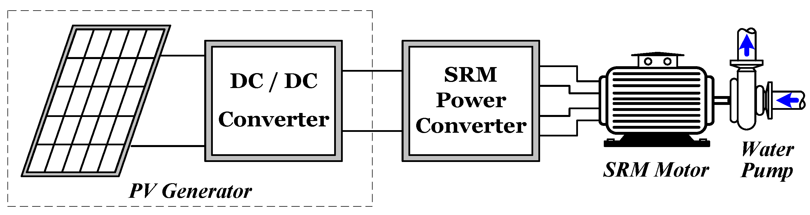
As mentioned in the first section, SRMs are highly recommended for application to pumping systems. However, these motors require a power converter. On the other hand, if the system is supplied by
PV panels, a DC–DC converter between those panels and the SRM power converter is usually required. This typical structure is shown in
Figure 1, where it is possible to see the three main parts, the PV generators, the power converter, and the SRM.
SRMs are typically supplied by two-level power converters. However, as mentioned previously, multilevel converters present several advantages, due to which they are an increasingly interesting alternative. However, these converters do not provide fault-tolerant operation or require a high number of switches. Therefore, a multilevel converter with fault-tolerant operation and a reduced number of switches is proposed in this work. The proposed solution, which is adapted for a 8/6 SRM, is presented in
Figure 2. As can be seen, this topology consists of two three-phase two-level voltage source inverters and extra switches. These extra switches are used to connect both positive buses of the three-phase voltage source inverters (bidirectional switch) and, in turn, to connect these to the upper capacitor. The PV generator is connected to the lower capacitor; accordingly, the voltage of the upper capacitor should be controlled.
When the converter operates in healthy mode, the bidirectional switch
SB is always off. This converter allows multilevel operation, since it allows the application of four voltage levels to each motor winding four voltage level, namely, +
VDC1 +
VDC2, +
VDC1, 0 and
–VDC1–VDC2. Therefore, there are four possible topological arrangements, as shown in
Figure 3 for the case of phase A. The application of the maximum positive voltage (+
VDC1 +
VDC2) is obtained when the power semiconductors
T1U,
T1L, and
T5L are ON (
Figure 3a). The intermediate positive voltage (
+VDC1) is obtained with the two power semiconductors
T1L and T
5L in ON state (
Figure 3b). Regarding the state associated with the 0 voltage, it is obtained when diode
D4L and transistor T
5L are ON (
Figure 3c). This last state can also be achieved with the diode D
2L and transistor T
1L in the ON condition. Finally, for the last state (the application of the negative voltage
–VDC1–VDC2), the diodes
D2L and
D4L are ON (
Figure 3d).
One important characteristic of the proposed topology is that during an open switch fault, it can provide fault-tolerant capability. This fault-tolerant capability is achieved by changing the switches that are controlled under the concept of the bidirectional current excitation. Let us consider the example of a fault in the transistor
T1L. During this kind of fault, it is not possible to apply a positive voltage to the motor winding phase A. Thus, to settle this problem, instead of using transistors
T1L and
T5L, transistors S
2L and
T4L are used. Consequently, the current in the motor winding phase A flows in the opposite direction when compared with the healthy condition. In
Figure 4, it is possible to analyze the new circuits for this fault-tolerant mode. If the fault is in the upper switch, such as T
1U, then when the maximum voltage applied to the motor windings A or C is needed, instead of this transistor, transistor
T2U and the bidirectional switch
SB should be used. The new circuits for this fault condition can be observed in
Figure 5. It should be noted that for this kind of fault, the change in direction of the current excitation is not needed.
Through the analysis that was performed for the proposed topology, it was possible to confirm the system’s fault-tolerant capability. As verified, this capability was achieved by changing the transistors that were being used by other ones and in some conditions by the inversion of the current excitation in the winding affected by the fault.
Since the developed topology was designed with the purpose of reducing the number of switches and drives for the transistors, there is a consequence regarding the power switches’ balanced losses. In fact, this is the disadvantage of this topology, since the two upper switches, T1U and T2U, will experience greater power losses, since each of them are common to two phases. However, this fact is true for higher motor speeds, since it is in these operational modes that the maximum positive voltage is required. For lower speeds, it is the contrary. In this last case, the maximum voltages are practically not required; accordingly, the upper switches are not operated.
4. Control of the Proposed Converter
To control the proposed multilevel fault-tolerant converter, from the point of view of the motor, several approaches can be used. For this work, a current controller for the motor windings was used. The adopted approach can be seen in
Figure 6, where the full scheme is presented. As shown in this figure, the current controller is associated with a modulator that is specially developed for this fault-tolerant converter.
The current controller is responsible for the regulation of the motor winding currents. For this purpose, a current hysteresis controller was used, but designed to allow the generation of the four voltage levels (generating at their output four different values that are associated with the switch combination to generate the required voltage). In this way, the controller followed the conditions presented in Equation (7). The generation of the four different values can also be seen in
Figure 7.
A modulator is developed to generate the switch combination as a result of the current controller. Therefore, considering the four values at the output of the current controller (λ), the switches that must be turned ON and OFF, associated to phase A, are given by in
Table 1. In this table, several possible conditions are presented, being the negative signal of the current the representation of the inversion of the current excitation in the winding.
Another aspect that must be considered is the control of the capacitor voltage. The capacitor voltage
VC1 is controlled by an outer loop that gives the current reference. For this loop, a PI controller is adopted. The scheme of this outer loop can be seen in
Figure 8.
Another aspect that needs to be considered is the balance of the floating capacitor voltage VC2. This balance is ensured by the definition of a voltage reference for that capacitor and control of the switches T1U and T2U as a function of this reference. In this way, the gating signals of these switches are inhibited when the voltage of the capacitor C2 is higher than the reference value.
5. Reliability Evaluation
This section presents a brief study about the theoretical probability of failure expected from the classic NPC-AHB [
38] and the proposed fault-tolerant topology presented in
Figure 2, after a failure in the IGBTs of one phase (winding A). In this analysis, the open-circuit failure mode and the ability to reach the desired voltage level were considered. Reliability measures the probability of a system failing within a given time interval (0,
t), i.e., reliability is a function of time,
R(t) [
49]. With a constant failure rate component, λ, reliability is determined by an exponential distribution (8):
The reliability of stand-by systems with redundancy, featuring ideal switching without repair and constant and identical failure rates, can be described by the Poisson distribution (9) [
50].
The probability of failure is then calculated by (10):
Table 2 and
Table 3, below, present the estimated probability of failure after five years (5 × 8760 = 43800 h) of operation and with a constant failure rate of
λ = 1.6577 × 10
−6 h
−1 (failure rate according to Coffin–Manson method [
51]) for the NPC-AHB and the proposed topology after the first failure regarding different power devices and desired voltage levels.
From this analysis, it is possible to conclude that the proposed solution is much more reliable regarding the open circuit failure mode than the classic NPC-AHB, independently of the device under failure and desired voltage level.
6. Simulation Results
The proposed PV generator feeding a water pumping system based on an SRM with a multilevel fault-tolerant converter was first tested by computer simulations. The simulation of this test system was performed through the use of MATLAB 2017a with Simulink version 8.9. Associated with this program, the Simulink Library, namely the Simscape/PowerSystems blockset, was also used. A discrete simulation type with a sampling time of 1 microsecond was also used. The model of the SRM was the model present in the examples of the Simulink. For the power semiconductors, the models present in the simscape/power systems/specialized technology/fundamental blocks/power electronics library were used. For these computer simulation tests, the capacitor C1 was connected to a PV generator that consisted of a PV panel and a classical DC–DC Boost converter. The PV panel allows the generation of a maximum power of 320 W. For the Boost and the proposed multilevel converter, an inductor of 0.4 mH and capacitors of 470 μF were considered.
The pumping system with the proposed multilevel power converter was initially tested under normal conditions. An irradiance of 1000 W/m
2 and a temperature of 25 °C were considered. For this test, a torque of 2.5 Nm and a speed of around 800 rpm were considered. The results of this test can be seen in
Figure 9. This figure presents the voltage applied to the motor winding A, as well as the motor winding currents. Analyzing
Figure 9a, it is possible to confirm the multilevel operation of the converter. Initially, when the motor winding A was excited, the maximum voltage was applied. Regarding the motor winding currents, it is possible to observe in
Figure 9b that they were controlled and the reference value was around 4 A. Another aspect that was analyzed was the efficiency of the power electronic converter. Taking into consideration this operating mode, the efficiency was 92.8%. Regarding the power losses of the transistors, it is also possible to see that the lower transistors (
T1L,
T2L,
T5L,
T6L,
T7U,
T8L,
T11L and
T12L) were in the ON condition for much more time than the upper transistors (
T1U and
T2U). However, each of the upper transistors was common to two phases. Therefore, in this mode of operation, the power losses of the upper transistors were similar to the losses in the lower transistors. For the upper transistors, the power losses were around 46.2% of the total losses, while for the lower transistors, they were 53.8%.
Another test in which the system was initially disconnected (capacitors discharged) and that turned ON when
t = 0 s under the same irradiance and temperature conditions as the previous test, was performed to analyze the behavior of the proposed pumping system with the proposed converter and controllers. The result of the voltage across both capacitors can be seen in
Figure 10. Through this figure, it is possible to confirm that initially, the capacitors were discharged and that, after connecting the system, they changed until they achieved the reference value. It is also possible to confirm that although, during the transient time, the voltages across the capacitors were different, they both stabilized with the same value (reference). In this way, it is possible to confirm that the controller ensured the balance between the capacitors.
Tests with the proposed converter in healthy, faulty, and fault-tolerant conditions were also performed. A test in which, initially, the converter operated in healthy mode, following after
t = 0.5 s with a fault in transistor
T1U and after
t = 0.52 s in fault-tolerant mode, can be seen in
Figure 11. This figure shows that after the switch fault, it was no longer possible to apply the maximum voltage (
VC1 +
VC2). However, this limitation disappeared after the reconfiguration of the circuit (fault-tolerant mode). In fact, analyzing the winding currents, it is possible to verify that between 0.5 s and 0.52 s (during the fault) they were affected and began to decrease their values. However, after the reconfiguration of the circuit, the winding currents started to recover. Another test, with a different fault, was also performed. In this case, the fault was in one of the switches of the three-phase modules, namely transistor
T1L. The consequences of this fault and operation in fault-tolerant mode can be seen in
Figure 12. After the fault (
t = 0.5 s), it was not possible to apply a voltage to the SRM winding of phase A. Therefore, the current in this phase was zero. To overcome this problem, the fault-tolerant mode was applied at
t = 0.52 s. In this last mode, the voltage was applied again to the SRM winding of phase A. However, as shown by the results of this last test, for this transistor fault, inverse voltages and negative currents to the SRM windings began to apply.
7. Experimental Results
The verification of the simulation tests and theoretical considerations was also confirmed by some experimental tests using a laboratorial prototype. For the Boost and proposed multilevel converter similar components used in the simulation tests, an inductor of 0.4 mH and two capacitors of 470 μF were considered. To provide the DC voltage to the system, a controlled EA PS8360-30 2U (up to 360 VDC, 30 A) power supply, adjusted to 200 VDC, was used. This power supply makes it possible to emulate the PV generator (PV panels + DC–DC converter) in different weather conditions. The system was connected to a four-phase 8/6 SRM, the new proposed inverter, circuit drives, and sensors. The pumping system was emulated through a DC machine operating as a generator connected to the shaft of the four-phase 8/6 SRM. The control algorithm of the SRM drive was performed on a DSPACE tool. For the power semiconductors, IXGN72N60C3H1 and CM600DY-13T IGBTs and MUR1540 diodes were selected. The waveform signals were acquired by a TDS3014C oscilloscope.
The first experimental test was performed in normal conditions (without failures) considering a stationary voltage and current from the power supply. In this situation, the PV generator (PV panels + DC–DC converter) presented 200
VDC, which corresponds to an irradiance of 1000 W/m
2, and the PV panels exhibited a temperature of 25 °C, boosted by the DC–DC converter. The first experimental result can be seen in
Figure 13, showing the multilevel voltage applied to the motor winding A (
Figure 13a) and the SRM winding currents (
Figure 13b). Analyzing
Figure 13, it is possible to confirm the desired multilevel operation of the converter and the controlled winding currents around the reference value (around 6 A). In this case, the current was slightly higher than the current presented in the simulations. However, this increase was due to the fact that the power supplied to the motor was adjusted to ensure the same speed, of 800 rpm. The efficiency of the power electronic converter in this operating mode was around 91.2%. This value was lower than the value obtained for the simulation, but it can be considered similar. Regarding the power losses of the transistors, they were also similar to the those obtained by simulation. In this case, the power losses of the upper transistors were around 43.8% of the total losses, while for the lower transistors, they were 56.2%.
Another experimental test was performed to analyze the behavior of the proposed system considering the initial conditions. In this experimental test, the power supply was initially disconnected and then switched on to evaluate the transient voltage in the input capacitors of the multilevel converter. The experimental results of the voltage across both capacitors considering these initial conditions can be seen in
Figure 14. Analyzing this figure, it is possible to observe that, initially, the capacitors were fully discharged and after switching ON the power source, the transient voltage increased until achieving the reference value. It can be seen that the adopted control strategy was able to stabilize and balance the voltages of both capacitors. The duration of this transient depended on the dynamics of several components and imposed load.
Another set of experimental tests was dedicated to analyzing the behavior of the system regarding the introduction of open-circuit failures in the power devices of the converter, making it possible to explore the features of the fault-tolerant operation. The first experimental result regarding the fault-tolerant operation can be seen in
Figure 15. In this test, an open-circuit failure in the transistor
T1U at a certain moment in time was introduced, showing the change from healthy to fault operation during a couple of periods. After the fault detection and circuit reconfiguration, the converter started the fault-tolerant operation. Notably, that the open-circuit failure in the transistor
T1U generated the loss of the maximum voltage level (
+VDC), since this device is an outer device connected to this voltage level. As a consequence, as demonstrated by the experimental results in
Figure 15a, after the open-circuit failure of this device, the converter only operated with
+VDC/2, which created difficulties for controlling the winding currents (
Figure 15b). After the introduction of the fault-tolerant operation, the voltages and currents returned to normal operation. Notably, this failure mode did not require the inversion of the winding currents.
A second experimental test of this kind was performed considering an open-circuit failure in one of the switches of the three-phase modules, the transistor
T1L. The experimental results of this test can be seen in
Figure 16. In
Figure 16a, it is possible to observe that this faut was introduced when the converter operated normally, creating a complete voltage loss in the winding of phase A. As a consequence of this fault, the voltage and current (
Figure 16b) of phase A are missing. After fault detection and reconfiguration of the circuit, it was possible to observe that the multilevel voltages and current returned to the reference values. Nevertheless, the fault in this device (and other devices in the three-phase modules) required winding voltage and current inversion. This was possible to perform thanks to the design adopted for the topology, allowing the creation of alternative paths to recover voltage levels regardless of the polarity, exploiting the characteristics of the SRM to achieve the desired fault tolerance.
Comparing these experimental results with those obtained by simulation, it is possible to verify that they are not precisely equal. However, it can be concluded that they are very similar. The small differences were expected, since in the simulation model, several components, such as the SRM, the power semiconductors, and the passive components, were simplified compared with the real components.
8. Discussion
As described above, a topology was designed to provide fault-tolerant capability but with a reduction of the power semiconductors and transistor drives in order to reduce the cost of the system. In
Table 4, a comparison with equivalent topologies with fault-tolerant capability is presented. In fact, this new topology only requires sixteen switches and two extra diodes. The topology presented in [
48] requires twenty-six switches and eight extra diodes. Furthermore, this topology also requires eight additional relays. Due to the number of switches and the requirement of additional relays, the cost of this converter is high. The topology presented in [
49] requires 32 switches and 16 extra diodes. It does not require extra relays, but the number of switches is very high; accordingly, the cost is also high. A topology that also presents multilevel characteristics and a reduced number of switches is presented in [
35]. This topology requires the same number of switches as the proposed topology, but a higher number of diodes. On the other hand, it does not provide full fault-tolerant operation, since for some faults, it does not offer the ability to restore the initial operation. Another aspect is the modularity, for which the topologies [
35,
47] present low abilities. On the other hand, the topology of [
48] presents a high capability regarding the modularity, since it uses NPC legs that are also used in the drives. Regarding the proposed topology, it can be considered as medium, since in part of the circuit, it is possible to use classical three-phase two-level inverter modules.


 ,
, 


