Article

A Smart Fault-Tackling Strategy Based on PFTE for AC Three-Phase-to-Ground Faults in the Multi-Terminal HVDC Wind Power Integration System: Further Foundings

1
College of Mechanical and Electrical Engineering, Xinxiang University, Xinxiang 453003, China
2
Dispatch Control Center, State Grid Corporation of China (SGCC), Beijing 100031, China
*
Author to whom correspondence should be addressed.
Energies 2022, 15(3), 768; https://doi.org/10.3390/en15030768
Submission received: 25 December 2021 / Revised: 12 January 2022 / Accepted: 18 January 2022 / Published: 21 January 2022

Abstract

:
This paper describes a smart fault tackling strategy based on power flow transfer entropy (PFTE) for AC three-phase-to-ground (TPG) faults in the multi-terminal HVDC (MTDC) wind power integration system. The fault characteristics and transient energy transfer of different positions and properties are analyzed. Then, a double integral discrimination method based on PFTE is proposed to further distinguish the fault property. Considering the power flow balance, an adaptive coordination strategy of wind farms and energy dissipation resistors is proposed to deal with different AC faults. Finally, a smart fault-tackling strategy based on PFTE for AC three-phase-to-ground (TPG) faults in the MTDC wind power integration system is proposed. Under the proposed smart fault-tackling strategy, the MTDC wind power integration system achieves uninterrupted operation during any AC TPG fault at the receiving end. The experiment results confirm the applicability of the proposed fault-tackling strategy.

1. Introduction

With the transformation from traditional fossil energy to clean energy in the 21st century, wind power has broad application prospects due to its pollution-free and easy transformation characteristics [1,2]. In 2020, China’s installed wind power capacity showed explosive growth, reaching 71 GW, which ranked it first in the world [3]. Modular multilevel converter (MMC)-based high voltage direct current (HVDC) technology can directly connect to weak AC systems and has no transmission distance limit and no risk of commutation failure [4,5]. To achieve further rational integration, distribution, and consumption of onshore wind power, the MMC-based, multi-terminal HVDC (MTDC) wind power integration system has received notable interest [6,7,8].
The MTDC wind power integration system has the advantages of having no transmission distance limitation, no commutation failure, and enriched system efficiency [9,10]. However, it is undeniable that faults are prone to spreading in the DC grid due to its reticulate structure [11,12]. When an AC three-phase short circuit fault occurs on the valve side of the receiving MMC station, the transient excess power generated by the maximum power tracking control operation of the wind farms cannot transmit into the AC grid [13]. The surplus wind power causes an overvoltage in the DC line, and the converter station sub-module capacitance voltages also rise consistently [14,15]. If the MMCs remain unblocked, the whole HVDC power transmission system may break down.
To protect the safety of the HVDC power transmission system during AC faults, [16] proposed a voltage droop control in the wind farm to quickly reduce power when the DC voltage deviation exceeds the threshold value of 0.1 pu. However, the approach is only effective in point-to-point HVDC wind power integration systems. In [17], power reduction control in the wind farm MMC (WFMMC) of an MTDC wind power integration grid by detecting the DC voltage variation was proposed. However, this method cannot locate on which receiving grid an AC fault has occurred, and power transmission is entirely interrupted during the fault. Furthermore, even though traditional AC relay protection has fault location capability, the measurement signals are enormous, and the protection setting calculation in the MTDC wind power integration system is complex [18,19]. Currently, effective detection and location methods for receiving AC faults in MTDC grids, especially those integrated with wind farms, are lacking.
In [20], fault detection criteria based on power flow transfer entropy (PFTE) is proposed to locate the AC fault’s position. This method uses the power flow trend of the DC line to locate AC fault quickly, with less measured signal and no complex setting calculation. More importantly, this method realizes the remote fault detection and location of more than 100 km so that the converter station can perceive the fault location independently of the communication system.
However, the literature [20] lacks further analysis and application of PFTE, and the criteria have difficulty with permanent AC faults. To enable the system to cope with permanent AC faults, property identification of the faults is an essential middle link. Unlike DC faults, to ensure that the non-fault terminals are not severely affected, DC circuit breakers usually remain closed when AC faults occur. Hence, it is impossible to determine permanent faults by reclosing the circuit breaker. Additionally, methods based on AC circuit breakers are invalid because the operation delay time of AC circuit breakers is too slow to meet the requirements of the HVDC grid [21]. Therefore, it is important to determine how to identify the fault property without relying on the DC and AC circuit breakers.
Additionally, most existing methods can only solve one particular fault but are invalid for use with other faults. In [22], a reactive power compensation and AC voltage margin control method is proposed to suppress the rise in DC voltage during transient AC faults. However, when permanent faults occur, unbalanced power is continuously injected into the sub-modules. Then, the voltage equalization module and the inner-loop current control break down, leading to a severe DC overvoltage hazard. In [23], a DC braking resistor was proposed to achieve transient AC fault ride-through, but this causes the DC braking resistors to operate for long, causing them to become overheated when permanent faults occur. In [24], power coordinative control with braking resistors was proposed to solve permanent AC faults, but this method reduces power transmission and delays the system’s recovery time in transient AC faults. Further, the above fault ride-through methods have little fault location capability in the MTDC grid.
To solve the above problems, based on the literature [20], the characteristics of PFTE are further analyzed and utilized in this paper, proposing the fault property criteria based on PFTE to distinguish permanent and transient faults. Then the adaptive coordination strategy of wind farms and energy dissipation resistors is proposed to deal with different AC faults. Finally, combined with the fault location strategy proposed in the literature [20], a smart fault-tackling strategy based on PFTE for AC three-phase-to-ground (TPG) faults in the MTDC wind power integration system is proposed in this paper. The contributions of this study are as follows: A novel AC fault location and property identification approach based on the PFTE is proposed. Dissipation resistors (DRs) and power reduction control of the wind farms are conducted to achieve power rebalance in the system. Under the proposed smart fault-tackling strategy, the MTDC wind power integration system achieves uninterrupted operation during any AC TPG fault at the receiving end.
This paper is organized as follows: Section 2 introduces the configuration and control strategy for the MTDC wind power integration system. The fault characteristics and transient energy transfer of different positions and properties are analyzed in Section 3. Section 4 proposes a smart fault-tackling strategy based on PFTE for AC TPG faults in the MTDC wind power integration system, which includes fault location, transient energy dissipation, fault property identification, and coordinative control of the wind farm and DR. In Section 5, the validation results demonstrate the validity of the proposed methods. Conclusions are drawn in Section 6.

2. Configuration and Control Strategy for the MTDC Wind Power Integration System

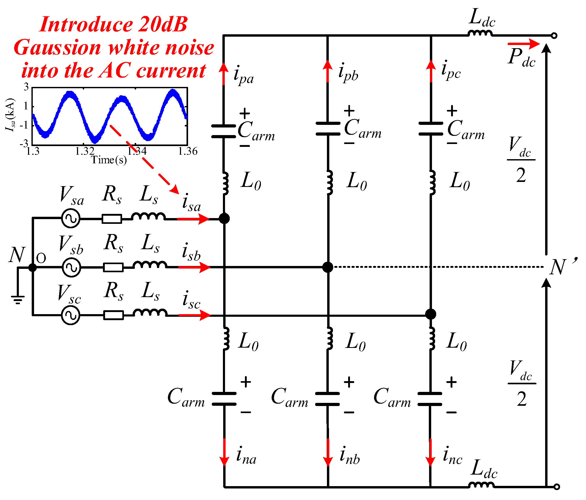
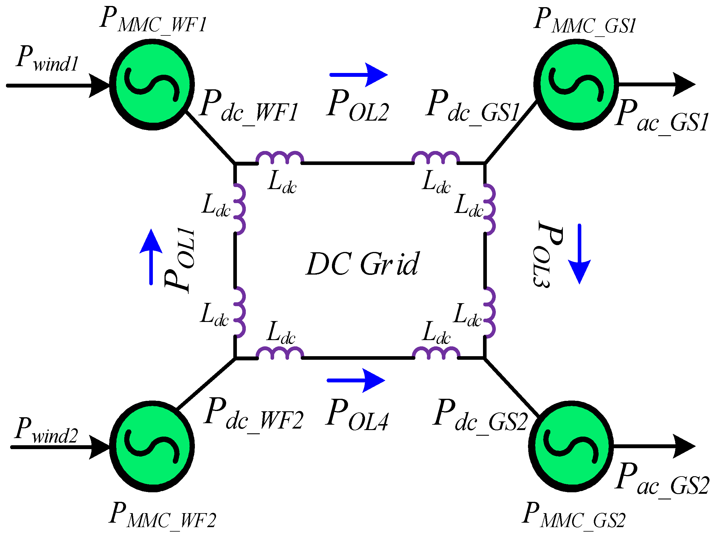
2.1. Configuration of the MTDC Wind Power Integration System

The configuration of the MTDC-integrated wind power system is shown in Figure 1a. Wind farms 1 and 2 use permanent magnet synchronous generators (PMSG) with an integrated wind rating of 1500 and 3000 mw. Each PMSG is connected to a full-power converter composed of generator side VSC (GS VSC) and integrated side VSC (IS VSC). In the MTDC power grid, MMC stations are composed of hundreds of half-bridge sub-modules (HBSMs), and power transmission depends on overhead lines (OL1~OL4). To absorb the excess energy, dissipation resistors R1 and R2 consisting of multiple resistors in parallel are installed on the AC side of WFMMC2, as shown in Figure 1a.

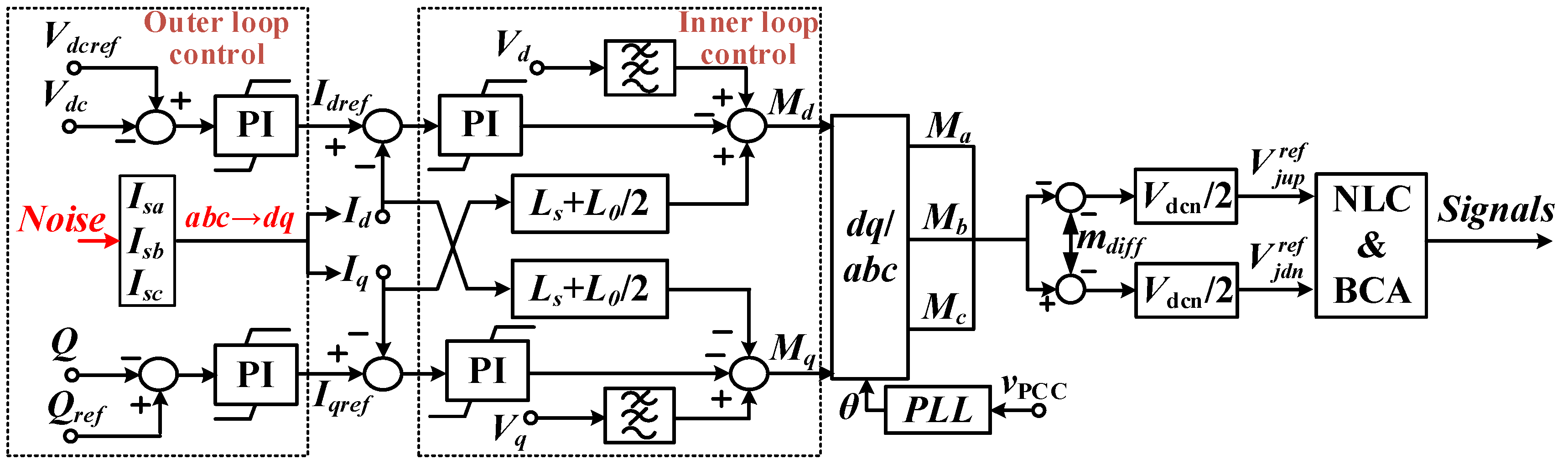
2.2. Control of the MTDC Wind Power Integration System

(1) System level control
The control system of the MTDC wind power integration system includes wind farm control, WFMMC control, and grid side MMC (GSMMC) control. The wind farms adopt maximum power point tracking (MPPT)-based active power control to generate the rated power. Since wind farms rely on a stable AC voltage supply for integration, WFMMCs are set at a constant AC voltage. GSMMC1 adopts active power control to balance the power flow among the rectifier and inverter side MMC stations, and GSMMC2 adopts DC voltage control to stabilize the voltage in the MTDC grid.
(2) Converter level control
Each wind farm uses a direct-drive, permanent-magnet-type wind turbine [25], and the power is controlled by the cooperation of GS VSC and IS VSC, whose simplified control system is shown in Figure 1b. The pitch and torque controller, which carries out pitch angle control, torque control, and pitch compensation control, prompts the angular frequency ωm to coincide with the reference value ωref. The outer controller decouples the output power P ω and Q ω to generate I g d q . Then, the dq current controller produces a reference voltage V g d q for the SVPWM. The d-axis of the IS VSC uses constant DC voltage ( V d c ) control to balance the power flow, and the reference value of the q-axis reactive power ( Q i ) is set to zero.
As shown in Figure 1c, the DC power ( P d c ), DC voltage ( V d c ), or AC voltage( V a c ) is adopted as the controlled variable of the outer controller to meet the needs of different application scenarios. The dq current controller produces a modulation ratio m d q based on the external controller’s input signal I d q . Then, the inner MMC controller sends the dynamic sub-module switching number to the arm controller to generate each arm voltage (Varm).

3. Analysis of Fault Characteristics and Transient Energy Transfer

To analyze the mechanism associated with AC TPG faults on the MTDC wind power integration system, the simplified equivalent circuit of the MTDC grid is displayed in Figure 2. As shown in Figure 2, Pwind1 and Pwind2 represent the output power of wind farms 1 and 2; Pdc_WF1 and Pdc_WF2 represent the DC transmission power of WFMMC1 and WFMMC2; Pdc_GS1 and Pdc_GS2 are the received DC power of GSMMC1 and GSMMC2; Pac_GS1 and Pac_GS2 are the AC transmission power of GSMMC1 and GSMMC2; and PMMC_WF1, PMMC_WF2, PMMC_GS1, and PMMC_GS2 represent the instantaneous power of each converter station.
Since MMC relies on sub-module capacitors and arm inductors to store energy, the energy storage of each MMC is calculated as
E M M C = 6 1 2 N C V c a v g 2 + 1 2 L I j k 2
where Vcavg is the average capacitor voltage of all SMs in the MMC, and Ijk (j = a, b, c; k = up, dn) is the instantaneous current of each leg.
Take the derivative of EMMC, there is
{ P M M C _ W F 1 = ( 6 N C 1 V c a v g W F 1 d V c a v g W F 1 + L 1 I j k W F 1 d I j k W F 1 ) / d t P M M C _ W F 2 = ( 6 N C 2 V c a v g W F 2 d V c a v g W F 2 + L 2 I j k W F 2 d I j k W F 2 ) / d t P M M C _ G S 1 = ( 6 N C 1 V c a v g G S 1 d V c a v g G S 1 + L 1 I j k G S 1 d I j k G S 1 ) / d t P M M C _ G S 2 = ( 6 N C 2 V c a v g G S 2 d V c a v g G S 2 + L 2 I j k G S 2 d I j k G S 2 ) / d t
where N represents the SM arm input number; C1 and L1 represent the SM capacitance and arm inductance of WFMMC1 and GSMMC1, respectively; and C2 and L2 represent the SM capacitance and arm inductance of WFMMC2 and GSMMC2, respectively.
Under normal operating conditions, the MTDC grid power balance equation is
{ P d c _ W F 1 = P O L 2 - P O L 1 + 2 L d c I d c d I d c / d t P d c _ W F 2 = P O L 1 + P O L 4 + 4 L d c I d c d I d c / d t P d c _ G S 1 = P O L 2 - P O L 3 - 2 L d c I d c d I d c / d t P d c _ G S 2 = P O L 3 + P O L 4 P d c _ W F 1 + P d c _ W F 2 = P d c _ G S 1 + P d c _ G S 2 + 8 L d c I d c d I d c / d t
According to Figure 2, the AC and DC balance equation of MMC is
{ P w i n d 1 = 6 N C 1 V c a v g W F 1 d V c a v g W F 1 / d t + P d c _ W F 1 P w i n d 2 = 6 N C 2 V c a v g W F 2 d V c a v g W F 2 / d t + P d c _ W F 2 P d c _ G S 1 = 6 N C 1 V c a v g G S 1 d V c a v g G S 1 / d t + P a c _ G S 1 P d c _ G S 2 = 6 N C 1 V c a v g G S 1 d V c a v g G S 2 / d t + P a c _ G S 2
where C1 and L1 are the capacitance of sub-module and arm inductance of WFMMC1 and GSMMC1, respectively and C2 and L2 indicate the capacitance of sub-module and arm inductance of WFMMC2 and GSMMC2, respectively.
According to the power balance equation of the DC grid, this paper analyses the AC faults at different locations and with different properties, including the following four types of faults:
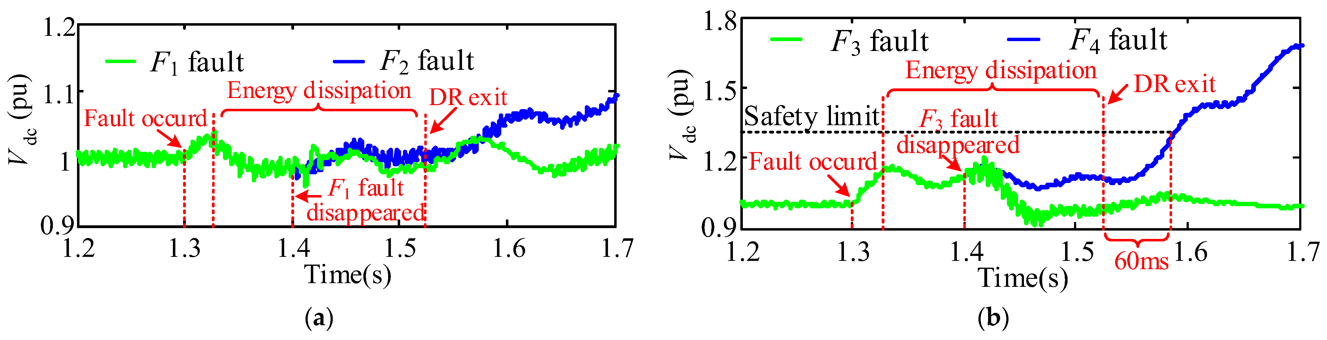
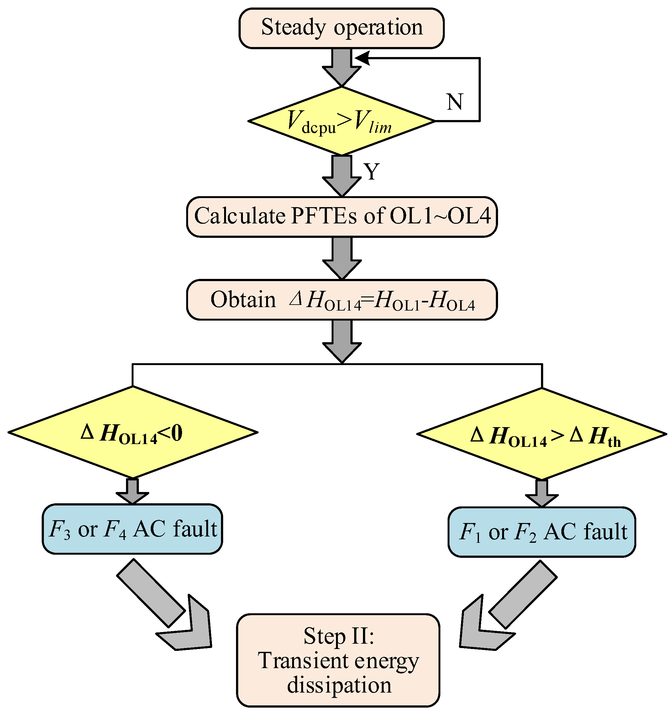
  • F1 fault: instantaneous AC TPG fault on the converter at GSMMC1;
  • F2 fault: permanent AC TPG fault on the converter at GSMMC1;
  • F3 fault: instantaneous AC TPG fault on the converter at GSMMC2;
  • F4 fault: permanent AC TPG fault on the converter at GSMMC2.

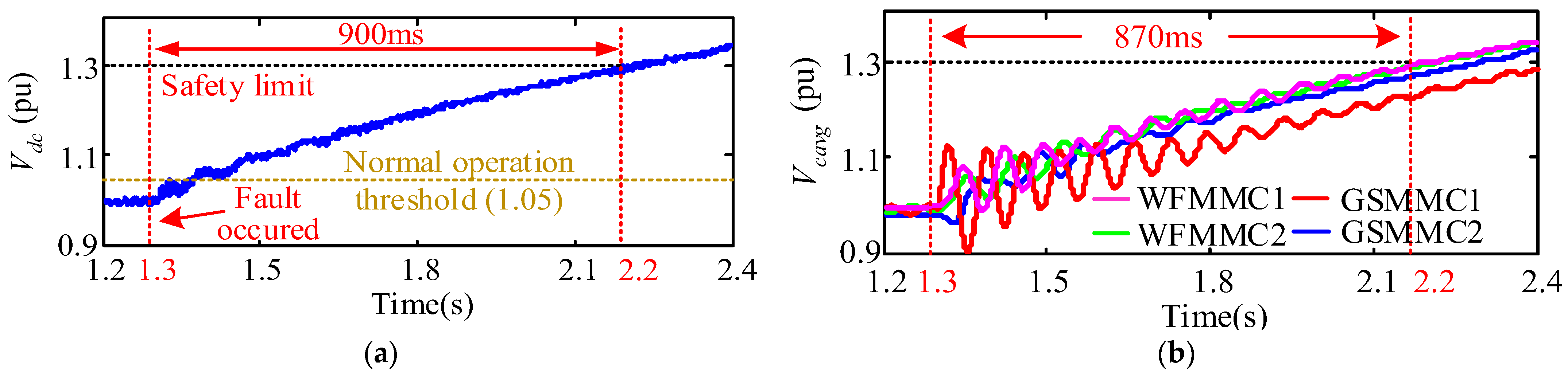
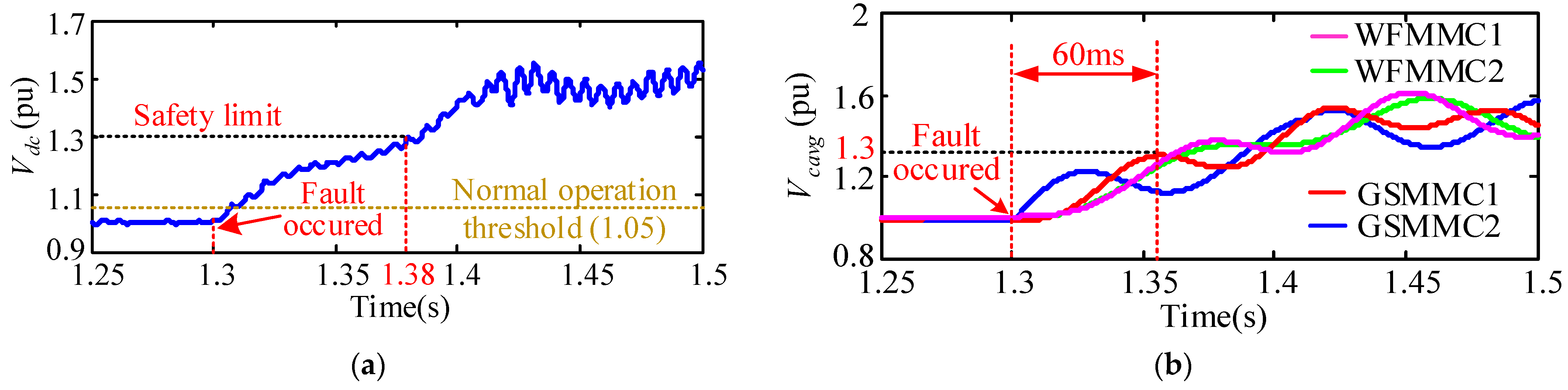
3.1. Analysis of AC Faults at Different Positions

Compared with SM capacitors, the power fluctuation in the arm inductance hardly varies, which can be ignored to simplify the analysis.
In the case of an F1 (or F2) fault, Pac_GS1 immediately decreases to zero. Since the MMC isolates its AC and DC sides, the value of Pdc_GS1 will not instantly drop, so V c a v g G S 1 rises causing an overvoltage according to the Equation(4). Then, the active power control of GSMMC1 becomes invalid, and the surplus wind power also feeds into the SM capacitors of GSMMC2, causing an overvoltage in V c a v g G S 2 .
In the MTDC grid, GSMMC2 adopts constant DC voltage control, and its DC side voltage is
V d c _ G S 2 = N V c a v g G S 2 V C 2 N
where VC2N represents the rated voltage of each sub-module capacitor in the GSMMC2. Thus, the DC voltage of GSMMC2 increases with V c a v g G S 2 during the AC fault procedure. Since it is located at the end of the OL4, according to the capacitance-boosting effect, the increase in V c a v g G S 2 further causes the transmission power to drop, resulting in an insufficient load supply. According to Figure 3, the DC voltage and sub-module voltage of GSMMC1 exceed the safety limit of 1.3p.u at 900 ms after the fault occurs.
When an F3 (or F4) fault occurs, Pac_GS2 immediately drops down to zero, and P d c G S 2 decreases slightly, so the voltage of the sub-module capacitor V c a v g G S 2 rises. According to Equation (4), as wind farms operate in the rated power state, Pdc_WF1 and Pdc_WF2 remain constant. Thus, Pdc_GS1 and V c a v g G S 1 increase as the fault spreads. Since the fault occurs at the DC voltage-controlled station, the transient DC voltage and sub-module capacitor voltage rise more swiftly. As shown in Figure 4, the overvoltage of the sub-module capacitor exceeds the safety limit of 1.3 p.u at 60 ms after the fault has occurred.
Comparing the most severe permanent faults, AC faults at different positions all cause the DC voltage to rise. Assuming the conventional detection method based on the change amplitude of DC voltage is applied, when an F1 fault occurs, the DC overvoltage is still around the normal operation threshold (1.05 pu) within 70 ms of the fault occurrence, which may lead to protection-refusing actions.
The fault location must be determined within 60 ms of the fault occurrence or the DC overvoltage will exceed the safety limitation (1.3 pu). However, most AC fault protection methods take about 100 ms, which is not suitable for the MTDC wind power integration system. Therefore, other more apparent signals and more effective methods need to be adopted for fault location.
To analyze the relationship between DC transmission power and the AC fault position, the MTDC grid was disassembled, as shown in Figure 5.
According to the “torque method” of the ring network, power flow can be calculated as follows:
{ P O L 1 = ( Z O L 2 + Z O L 3 + Z O L 4 ) P d c _ W F 1 + ( Z O L 3 + Z O L 4 ) P d c _ G S 1 + Z O L 4 P d c _ G S 2 Z O L 1 + Z O L 2 + Z O L 3 + Z O L 4 P O L 4 = ( Z O L 1 + Z O L 2 + Z O L 3 ) P d c _ G S 2 + ( Z O L 1 + Z O L 2 ) P d c _ G S 1 Z O L 1 P d c _ W F 1 Z O L 1 + Z O L 2 + Z O L 3 + Z O L 4
In the DC network, the per unit length parameters of all lines are approximately equal, so Equation (6) can be calculated as
{ P O L 1 = ( l O L 2 + l O L 3 + l O L 4 ) P d c _ W F 1 + ( l O L 3 + l O L 4 ) P d c _ G S 1 + l O L 4 P d c _ G S 2 l O L 1 + l O L 2 + l O L 3 + l O L 4 P O L 4 = ( l O L 1 + l O L 2 + l O L 3 ) P d c _ G S 2 + ( l O L 1 + l O L 2 ) P d c _ G S 1 l O L 1 P d c _ W F 1 l O L 1 + l O L 2 + l O L 3 + l O L 4
According to Equations (4) and (7), the change in power flow in POL1 and POL4 is only related to the changes in Pac_GS1 and Pac_GS2, so the position of the AC fault can be determined via the change in the DC line power flow.

3.2. Analysis of AC Faults with Different Properties

Permanent faults last longer, have more negative significance and present more difficulty for system recovery than transient faults. In [26], a method involving using an energy dissipation resistor to achieve AC fault ride-through was proposed. However, the energy dissipation resistors (DRs) cannot operate continuously due to overheating and the high cooling cost. Once the DRs are out of operation, the DC voltage will rise again to attack the system, as shown in Figure 6. Therefore, additional power coordination control is necessary to allow the system to identify permanent faults accurately.
Generally, the determination of a permanent fault depends on the reclosing of AC or DC circuit breakers. However, when AC faults occur, the DC circuit breakers remain closed at all times, so this method is unable to be applied for fault property identification. Additionally, to ensure that the DC overvoltage does not exceed 1.3 pu when an F4 fault occurs, AC permanent fault identification should be completed within 60 ms of DR withdrawal, as shown in Figure 6b.

4. Smart Fault-Tackling Strategy Based on PFTE for AC TPG Faults

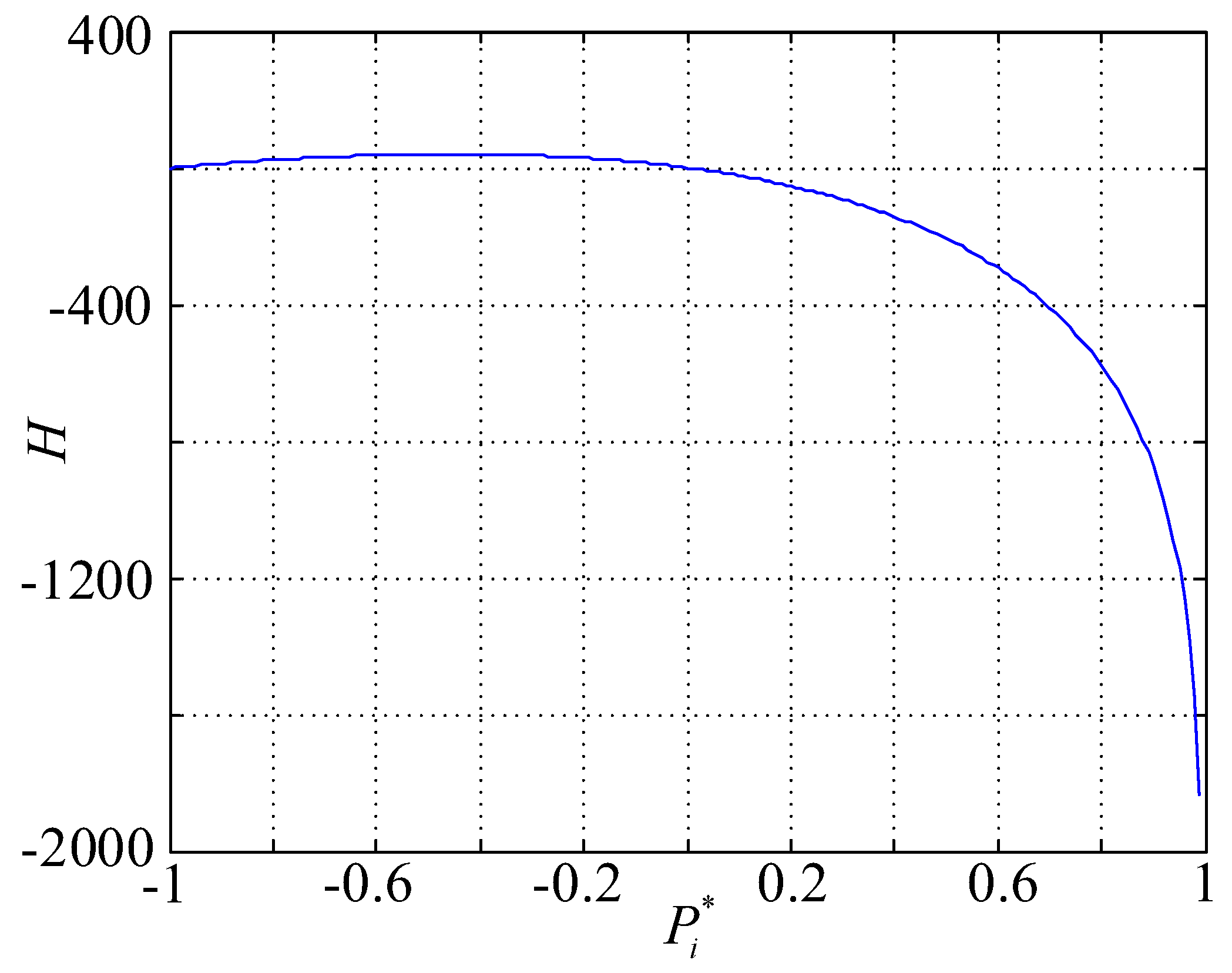
4.1. Power Flow Transient Entropy

According to Equations (4) and (7), the fault location can be determined by the two opposite DC transient power changes (POL1 and POL4). However, the power change of the MTDC grid is relatively slow, so the evolution of transient energy transfer cannot be predicted in advance. (The detailed proof is shown in Appendix A.)
In the MTDC power grid, the real-time dynamic balance of power generation and consumption is the premise of system stability. When the system occurs faults, the power flow is bound to change, so the power flow entropy can be used to reflect the state change trend of the system [27]. Reference [20] defined the power flow transfer entropy (PFTE) for the first time to reflect the DC line power flow change trend, which is expressed as follows.
H ( t ) = { K i = 1 m ( 1 + P i ( t ) ) ln ( 1 P i ( t ) ) - 1 < P < 1 K i = 1 m ( 1 + P i ( t ) ) ln ( P i ( t ) 1 ) P > 1
where m represents the number of DC lines between two converter stations. According to Equation (8), when P i (t) =1, PFTE is prone to negative infinity. To avoid the calculation of dead zone in the experimental system, the boundary of H(t) is set as [−1000, 1000]. P i (t) represents the load ratio of overhead line i at time t.
P i ( t ) = P i ( t ) / P ¯ i N , ( i = 1 , 2 , , N l )
where Pi(t) is the instantaneous power of the DC line i, P ¯ i N is the average transmission power of lines between two converters, Nl is the number of overhead lines in the MTDC grid. In the MTDC grid shown in Figure 1, under the rated operation, P ¯ i N is
{ P ¯ 1 N P ¯ 3 N = P W F 2 P W F 1 N l ( W F 1 - W F 2 , G S 1 - G S 2 ) P ¯ 2 N P ¯ 4 N = P W F 2 + P W F 1 N l ( W F 1 G S 1 , W F 2 G S 2 )
In the four-terminal MTDC wind power integration system, when the line is in a steady state, the value of PFTE is much lower than zero; otherwise, the PFTE value will be around zero. Based on the sensitivity of PFTE, the PFTEs of DC lines represent the trend of the transmission line from stable state to fault. The smaller its value is, the more stable the line state will be; otherwise, the line will be prone to fault occurrence.
By substituting Equation (7) into Equation (8), the PFTEs of OL1 and OL4 are expressed as
{ H O L 1 = K ( 1 + ( l O L 2 + l O L 3 + l O L 4 ) P d c _ W F 1 + ( l O L 3 + l O L 4 ) P a c _ G S 1 + l O L 4 P a c _ G S 2 l Σ α P ¯ 1 N ) ln | 1 ( l O L 2 + l O L 3 + l O L 4 ) P d c _ W F 1 + ( l O L 3 + l O L 4 ) P a c _ G S 1 + l O L 4 P a c _ G S 2 l Σ α P ¯ 1 N | H O L 4 = K ( 1 + ( l O L 1 + l O L 2 + l O L 3 ) P a c _ G S 2 + ( l O L 1 + l O L 2 ) P a c _ G S 1 l O L 1 P d c _ W F 1 l Σ α P ¯ 4 N ) ln | 1 - ( l O L 1 + l O L 2 + l O L 3 ) P a c _ G S 2 + ( l O L 1 + l O L 2 ) P a c _ G S 1 l O L 1 P d c _ W F 1 l Σ α P ¯ 4 N |
where lOL3 + lOL4 > lOL1 + lOL2, lOL4 < lOL1 + lOL2 + lOL3.
According to Equation (11), when an F1 fault occurs, ΔHOL14 = HOL1HOL4 increases. When an F3 fault occurs, ΔHOL14 decreases. Based on this, the PFTE can be used to locate the fault’s position. Since the logic discriminant signal (HOL1 and HOL4) and action protection equipment (DRs) are in the same converter station, the proposed method is not dependent on an additional communication system.

4.2. The Smart Fault-Tackling Strategy for Uninterrupted Operation of the System

On the basis of PFTE, this section proposes a smart fault-tackling strategy to support the system to determine fault locations and properties accurately. As a result, the extensive data from detection signals and the uncertainty of long-distance communication are eliminated. Therefore, the system can effectively ride through different AC TPG faults with minimized impact from the fault.
The smart fault-tackling strategy depicted in Figure 7 includes four steps: AC TPG fault location, transient energy dissipation, AC TPG fault property identification, and coordinative control of wind farm, and DRs. In Figure 7, SS1 and SS2 are control signals corresponding to dissipation resistors R1 and R2. ΔHOL14 represents the subtraction value of the power flow transfer entropy (PFTE) of OL1 and OL4. FNreset acts as the fault property identification signal. CDH1 and CDH2 are the two integral values of ΔHOL14.
In the proposed AC TPG fault diagnosis and ride-through method, instantaneous faults can be detected and located within 30 ms, and the DRs are input continuously for 200 ms. Then, after the DRs exit, the system returns to normal. Permanent AC faults can be accurately identified within 50 ms of the DRs exit. After 500 ms, the wind farm output power is decreased, and the system recovers. The details of each step are as follows.

4.2.1. Step I: AC TPG Fault Location Strategy

The AC fault location strategy is shown in Figure 8, where HOL1 and HOL4 represent the PFTEs of OL1 and OL4, respectively. When the DC voltage exceeds the normal operation threshold Vlim (1.05pu), the system is identified as having an AC fault. Then, if ΔHOL14 > ΔHth, the fault is located at GSMMC1, while if ΔHOL14 < 0, the fault is located at GSMMC2. In the proposed fault location strategy, once the fault position has been located, the result will be locked to prevent the strategy from running repetitively.

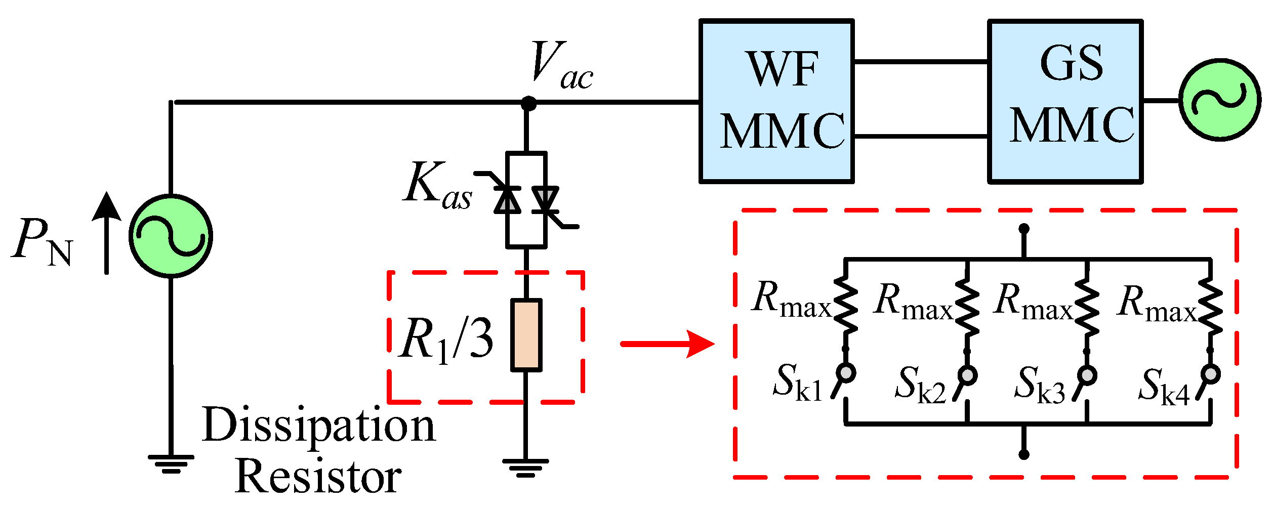
4.2.2. Step II: Transient Energy Dissipation

In prior research, the DRs have been placed on the onshore side to enable uninterrupted system operation when onshore AC faults occur [28,29]. However, the method cannot prevent surplus power from feeding into the WFMMC. Paralleling DRs on the AC side of WFMMC is a much safer method to protect all MMCs and other power electronics. Since the maximal amount of unbalanced power during the most severe AC fault is 3000 MW, installing DRs on the AC side of WFMMC2 can meet demands. To ensure a timely and bidirectional control response, the DRs are controlled by a couple of anti-parallel fast thyristors with less than 1 ms, as detailed in [30]. The layout of the dissipation resistor is shown in Figure 9.
To absorb the appropriate amount of surplus wind power under different situations, the DRs are divided into two groups (R1 and R2), symmetrically arranged in three phases. The energy dissipation resistor of each phase is composed of four resistors in parallel, and the Rmax can be calculated as:
R max = ( V a c / 3 ) 2 P N / 3 / 4 = 4 V a c 2 P N
where PN is the rated output of the wind farm and Vac is the AC line voltage. Based on the fault location criterion, the switching states of Rmax can be determined. When ΔHOL14 > ΔHth, the Ski(i = 1,2,3,4) of R1 is closed to dissipate 1500 MW of surplus wind power; when ΔHOL14 < 0, the DRs R1 and R2 are connected in the circuit to dissipate 3000 MW in total.

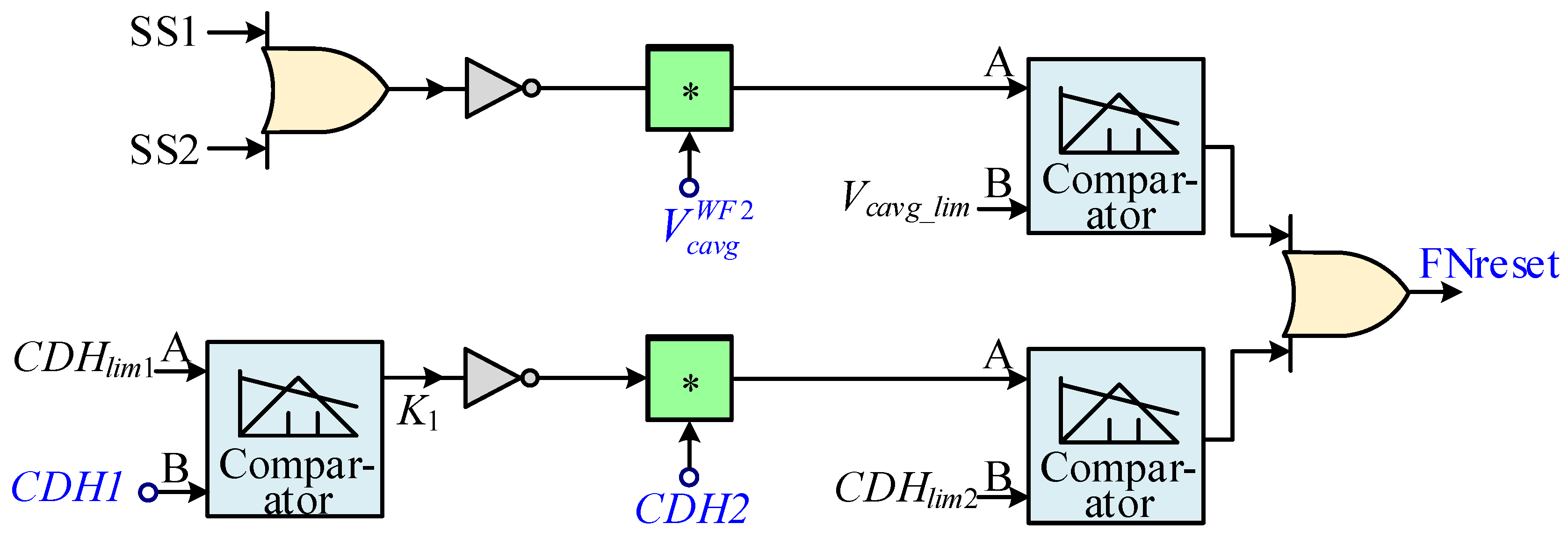
4.2.3. Step III: AC TPG Fault Property Identification

According to the analysis presented in Chapter 3.2, fault property identification must be completed within 60 ms after the DR exits.
Take the F2 fault as an example, before the dissipation device exits, almost the full power of the system is transferred to GSMMC2 and the energy dissipation resistor, and Pdc_GS1 is approximately equal to 0; after the energy dissipation device exits, Pdc_GS1 begins to increase again, while Pac_GS1 is still at zero.
According to Equation (3), there is
P d c G S 1 = 6 N C 1 V c a v g G S 1 d V c a v g G S 1
Thus, the SM capacitor voltage will rise again, leading to DC overvoltage and power transmission reduction of the system. Taking ΔHOL14 as the detection criterion, the comparison of ΔHOL14 in the two scenarios is shown in Figure 10a.
It can be seen from Figure 10a that when the DRs exit, the ΔHOL14 of the F2 fault rises sharply and generates a high pulse peak. However, the threshold value of ΔHOL14 has already been utilized for fault location. To avoid conflict with the fault location strategy, the ΔHOL14 integral is utilized to determine the fault property. The first integration at 100 ms after the input of DRs into the operation is done to locate the AC TPG fault occurrence position of the system and eliminate the interference of other faults; this is named as CDH1. The second integration at 50 ms after the exit of DRs is done to judge whether the fault is permanent or instantaneous; this is named CDH2, as shown in Figure 10b.
On the other hand, when an F4 fault occurs, since the amount of unbalanced power is relatively large after the exit of the dissipation resistance, the SM capacitor will experience overvoltage within tens of milliseconds. Therefore, it is also necessary to take the V c a v g W F 2 into account. The logic control diagram of the FNreset signal is shown in Figure 11, where CDH1 and CDH2 are the integral values of ΔHOL14, CDHlim1 and CDHlim2 are the corresponding thresholds, and Vcavg_lim is the threshold of the average SM capacitor voltage of the WFMMC2.

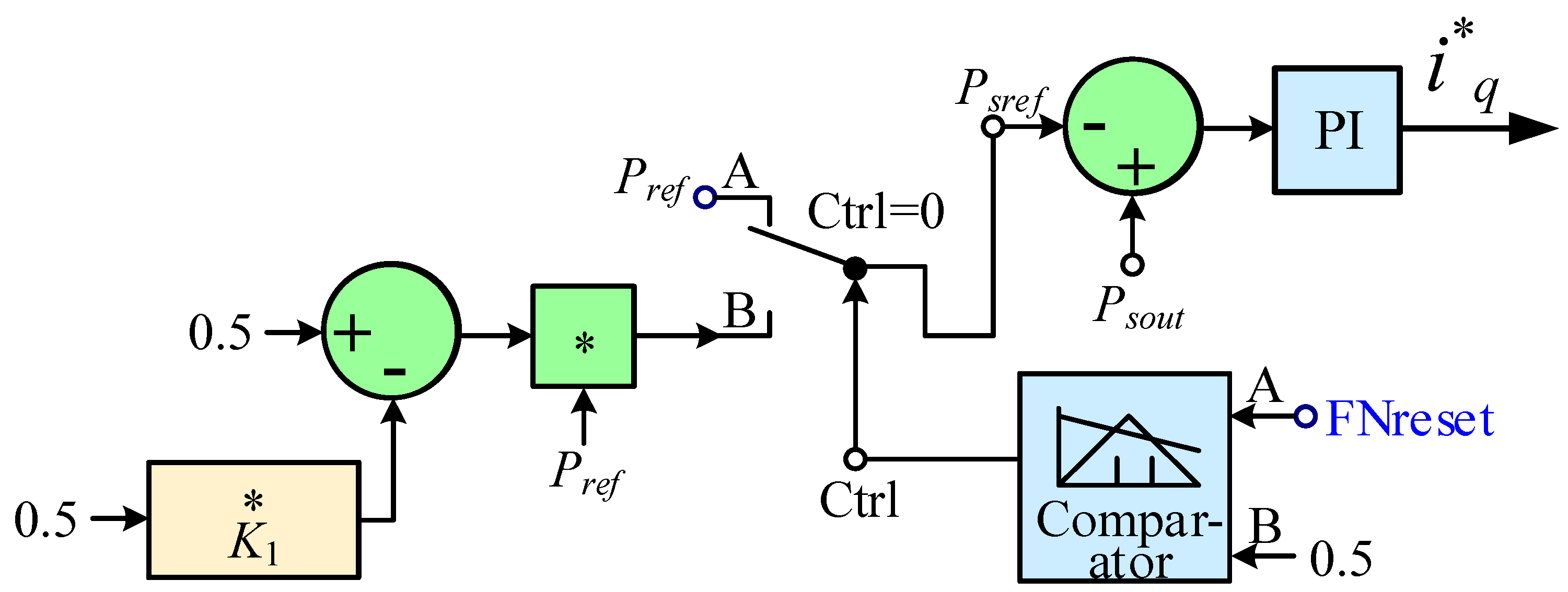
4.2.4. Step IV: Coordinative Control of the Wind Farm and DRs

To solve the permanent AC faults, the output of the wind farm needs to be reduced by its internal GS VSC. The enhanced power reduction control method is as follows:
In Figure 12, when the FNreset signal equals to 0, the Psref = Pref, and the wind turbine maintains rated output; when the FNreset signal equals jumps to 1, The comparator will convert the selector input to channel B, so the power reduction control is effective. The K1 and FNreset signals are transmitted by the WFMMC2 through cables. Referring to Figure 11, if a fault occurs on GSMMC1, then CDH1 > CDHlim1, K1 = 0; else, if the fault occurs on GSMMC2, then CDH1 < CDHlim1, K1 = 1. Considering the inertia time delay of the wind farm, it is necessary to cooperate with DRs during the decrease of the wind farm output power to ensure the safety of the system.

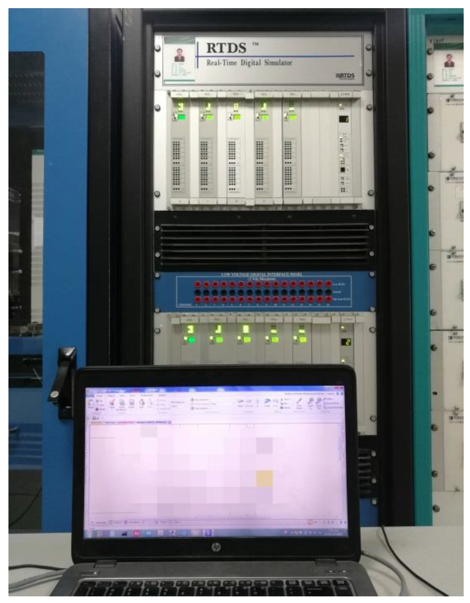
5. Validation Results

To verify the effectiveness of the proposed AC fault diagnosis and ride-through approach, the system shown in Figure 1 was built on RTDS setup. As shown in Figure 13, RTDS is composed of a GTWIF board and a PB5 board. The GTWIF board is connected with the workstation to ensure the synchronization of multi-core operation. The PB5 board acts as the processor to read and analyze the power system components and secondary controllers through the local area network. Since the positive and negative poles of each MMC are entirely symmetrical, the parameters of the unipolar MMC are listed in Table 1. The proportionality coefficient of PFTE was set as 200. The threshold of ΔHOL14 was 400. CDHlim1 = CDHlim2 = 200, and the limitation of the submodule-capacitor voltage was 1.2p.u.

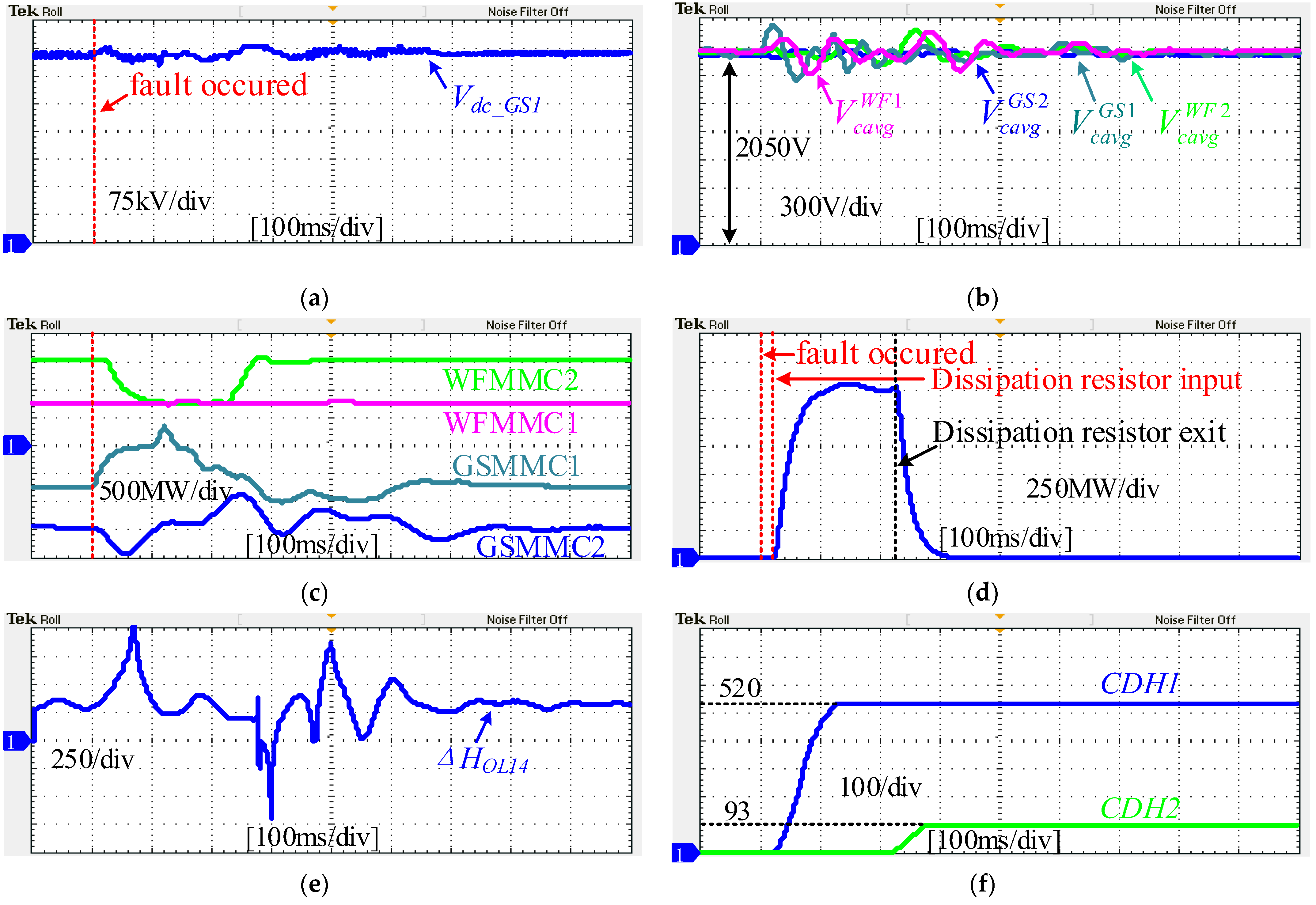
5.1. Diagnosis and Ride-through of the F1 Fault

The system first operated in the rated normal state for 1.2 s, which is the initial moment of the RTDS simulation record. Then, an F1 fault lasting for 0.1 s occurred at 1.3 s. During the fault, AC and DC circuit breakers remained closed, and the control strategies of the system were the same as during normal rated operation.
Figure 14a,b shows that both the DC voltage of the system and the capacitor voltage of each MMC increased after the fault occurred. During the first 20 ms after the fault occurred, the receiving power of GSMMC1 gradually decreased, but the receiving power of WFMMC1 and WFMMC2 remained the same as normal, as shown in Figure 14c. Thus, ΔHOL14 increased to the threshold ΔHth = 400, and the DRs were triggered. Figure 14d is the power absorbed by the DRs, which lasted for 200 ms and then automatically stopped. Subsequently, the fault property identification logic started. As CDH2 was always below the threshold, CDHlim2 = 200, the fault was determined to be instantaneous, as shown in Figure 14f. The system returned to normal rated power transmission after 1.8 s.

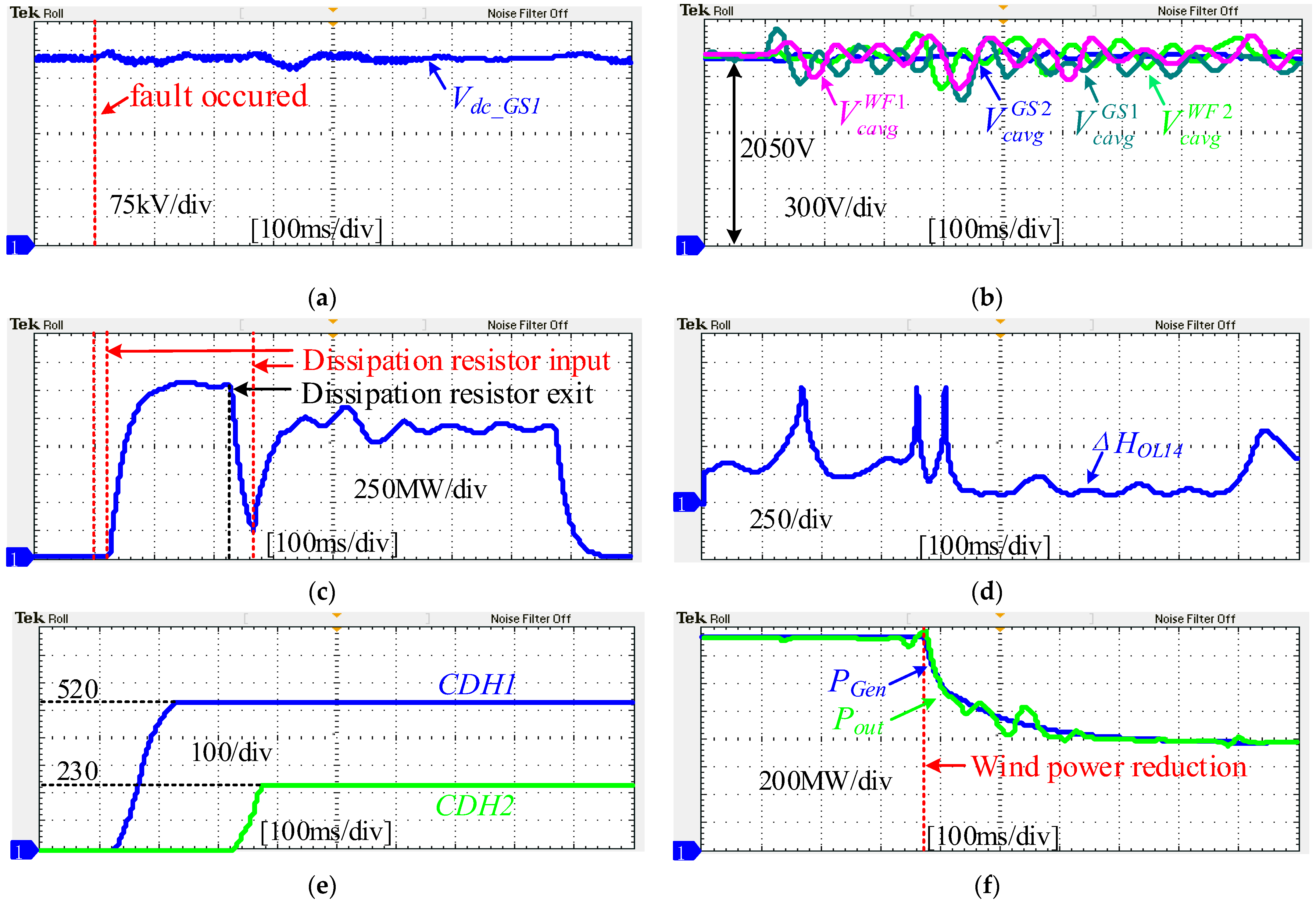
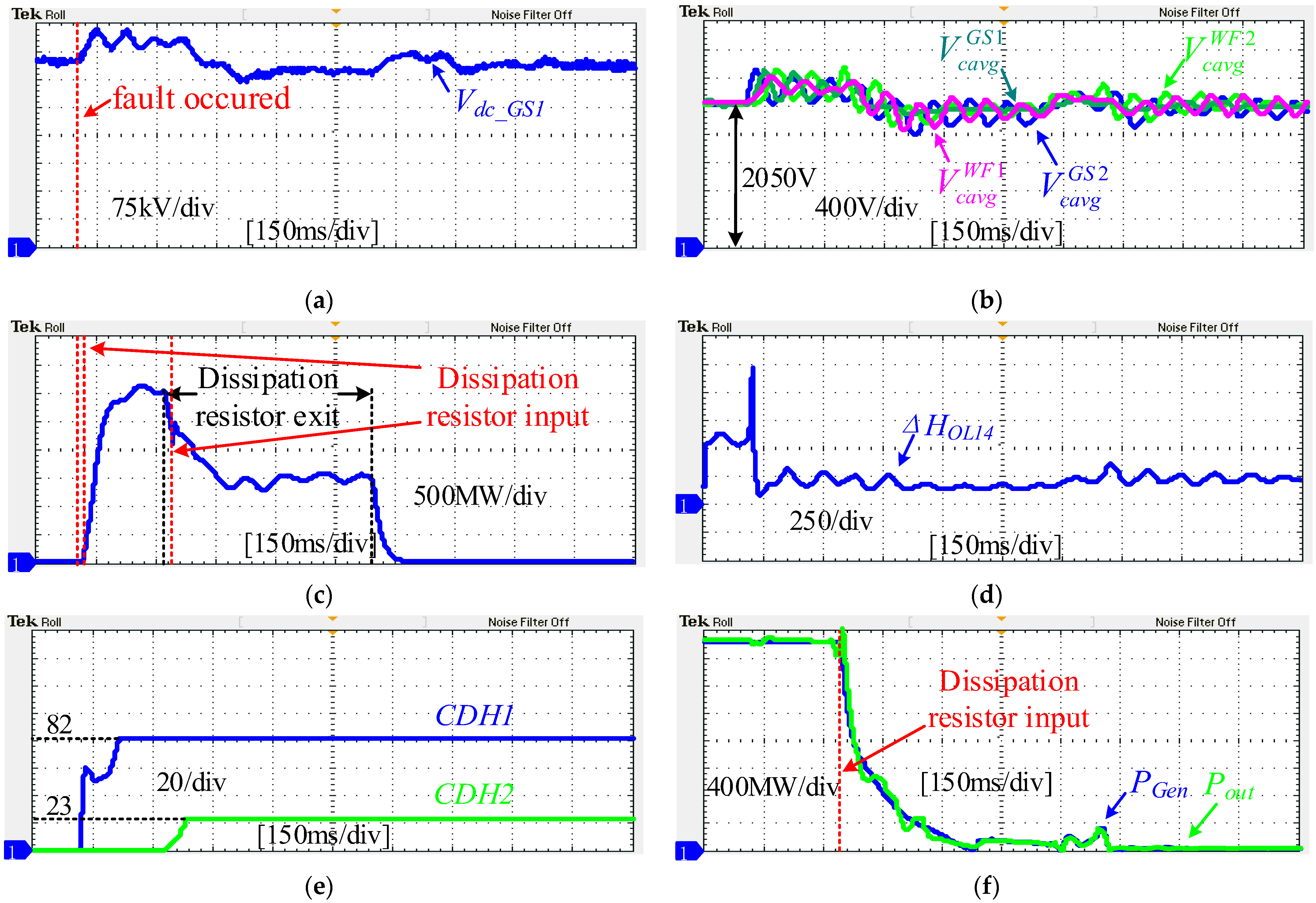
5.2. Diagnosis and Ride-through of the F2 Fault

The permanent F2 fault occurred at 1.3 s. Other conditions were consistent with those of F1.
Figure 15a,b show the DC voltage of the system and the capacitor voltage of each MMC increased as well. Owing to the proposed AC fault countermeasure, there was no overvoltage vision when the fault occurred. During the first 20 ms after the fault occurred, the power flow changes were the same as those for the F1 fault. Thus, the power absorbed by the DRs and ΔHOL14 was also the same, as shown in Figure 15c,d. After the DRs automatically exited, the fault property identification logic started. As CDH2 exceeded the threshold, CDHlim2 = 200, the fault was determined to be permanent, as shown in Figure 15e. The DRs were re-input to gain time for wind power reduction. After 500 ms, the output of the wind farm dropped to half that of the original, and the dissipation resistors were withdrawn (see Figure 15f). Then, the system resumed its normal operation after 2.0 s but was missing 1500 MW of wind power compared to the rated operation.

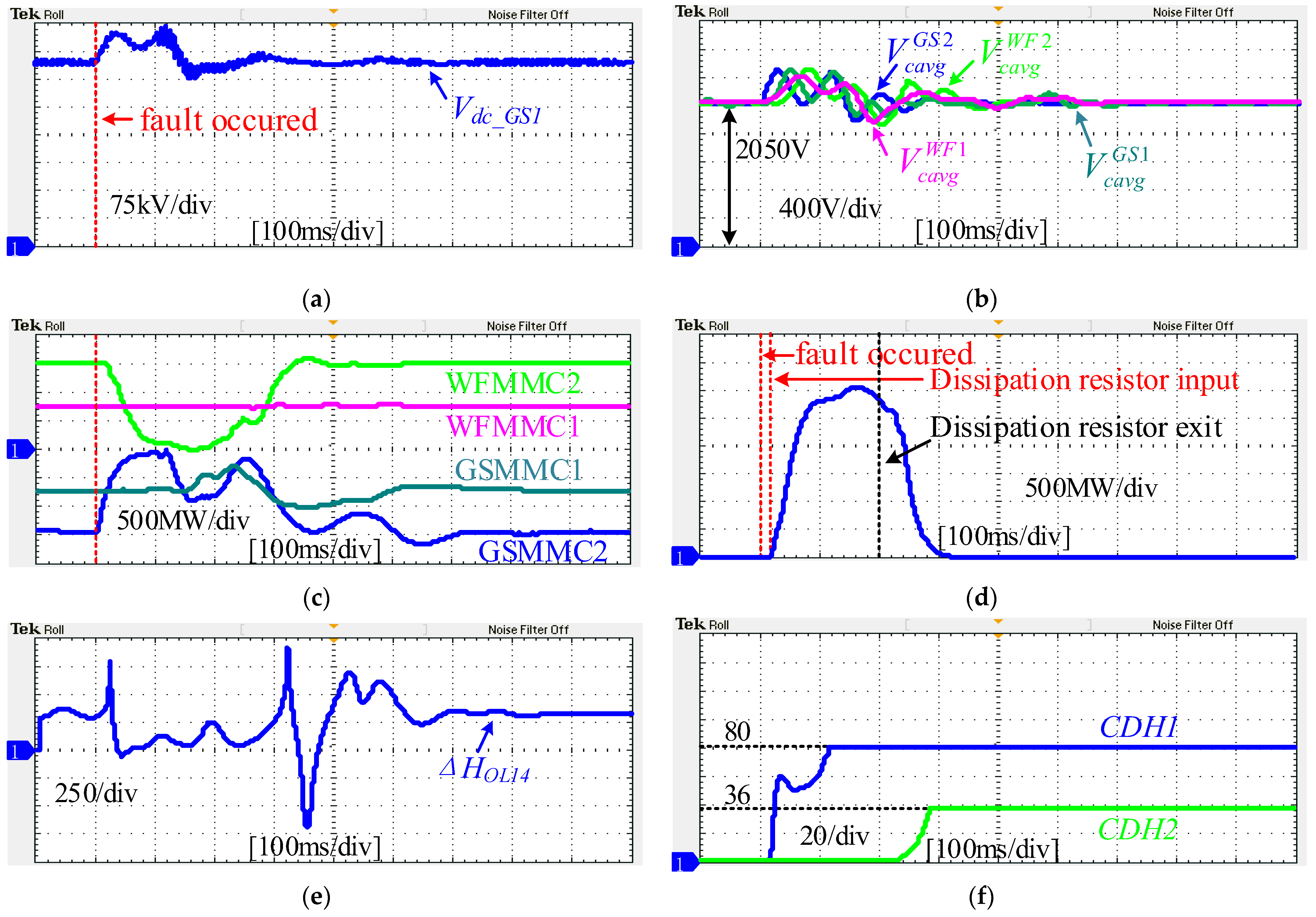
5.3. Diagnosis and Ride-through of the F3 Fault

The F3 fault occurred at 1.3 s and lasted for 0.1 s. The system response is shown in Figure 16. Figure 16a,b shows the DC voltage of the system. The capacitor voltage of each MMC increased slightly more than for the fault in GSMMC1 but was still under the safety threshold of 1.3 pu. During the first 20 ms after the fault occurred, the receiving power of GSMMC2 and WFMMC2 gradually decreased, but the receiving power of WFMMC1 remained the same as normal, as shown in Figure 16c. According to the Equation (11), ΔHOL14 first pulsed to 600 and then immediately dropped down to 0, so all DRs were triggered. Figure 16d shows the power absorbed by the DRs, 3000 MW for 200 ms, before they automatically exited. Subsequently, the fault property identification logic started. As CDH2 was always below the threshold, CDHlim2 = 200, the fault was classified as instantaneous, as shown in Figure 16f. The system returned to normal rated power transmission after 1.9 s.

5.4. Diagnosis and Ride-through of the F4 Fault

Finally, the F4 fault also occurred at 1.3 s, and the other conditions were consistent with the previous validation conditions.
Figure 17a,b show that the DC voltage of the system and the capacitor voltage of each MMC increased as well. Owing to the proposed AC fault countermeasure, there was no overvoltage vision during the fault. In the first 20 ms after the fault occurred, the power flow changes were the same as those for the F3 fault. Thus, the power absorbed by the DRs and ΔHOL14 was also the same, as shown in Figure 17c,d. After the DRs automatically exited, the fault property identification logic started. Although the CDH2 value, shown in Figure 17e, was always below the threshold of CDHlim2 = 200, the capacitor voltage of WFMMC2 exceeded Vcavg_lim = 1.2 p.u (see Figure 17b). Thus, the fault was classified as permanent. The DRs were re-input again to gain time for wind power reduction. After 500 ms, the output of the wind farm dropped to 0, and the DRs were withdrawn (see Figure 17f). Then, the system resumed normal operation after 2.1 s but was missing 3000 MW of wind power compared with the rated operation.

6. Conclusions

In this paper, a smart non-communication AC fault-tackling strategy including fault location and property identification is proposed for the MTDC wind power integration system. Additionally, an adaptive coordination strategy of wind farms and energy dissipation resistors is proposed to deal with different AC faults. Under the proposed smart fault-tackling strategy, the system can operate uninterrupted during any AC TPG fault at the receiving end. For instantaneous AC faults, the system can resume normal-rated operations within 600 ms of the fault occurrence. For permanent AC faults, the system can achieve secondary power balance within 800 ms of the fault occurs, and it can maintain maximal power transmission during the fault. In summary, this strategy greatly improves the anti-interference and power transmission efficiency of the MTDC wind power integration system.
So far, the effectiveness of this method is only verified in the four-terminal DC power grid. When the system has more end-drops (such as hierarchical connection mode), the characteristics of different AC faults may be more similar, leading to the failure of the criterion. Therefore, the AC fault ride-through in a complex system will be further studied.

Author Contributions

Conceptualization, C.D. and S.C.; methodology, C.D. and S.C.; software, Q.Z. and C.D.; validation, S.C.; formal analysis, C.D. and Q.Z.; writing—original C.D.; draft preparation, C.D.; writing—review and editing, C.D. and S.C. All authors have read and agreed to the published version of the manuscript.

Funding

This research was funded by the 2018 Henan Science and Technology Research Project (182102210121) and the 2020 Key Research Projects of Universities in Henan Province (20B470006).

Institutional Review Board Statement

Not applicable.

Informed Consent Statement

Not applicable.

Data Availability Statement

The study did not report any data.

Acknowledgments

Thanks to the College of Mechanical and Electrical Engineering, Xinxiang University and the Dispatch control center, State Grid Corporation of China (SGCC).

Conflicts of Interest

The authors declare no conflict of interest.

Appendix A

To depict the advantages of the adopted PFTE measurement method over the currently used measurement method, active power was taken as the intermediate variable, and the comparison was divided into two parts, as follows: (1) Detecting power is better than detecting current, since power can restrict current noise and (2) detecting PFTE is better than detecting power, since PFTE is more sensitive than power.
(1) Detecting power is better than detecting current since power can restrict current noise.
(1.a) Analysis of the current measurement method and the power measurement method for AC fault detection under current noise
Current noise is generally caused by electromagnetic interference, environmental noise, and measurement errors. If the current change is directly used for fault detection, it is difficult for the system to determine whether the fault or noise has generated the change, because the current change is not apparent at the beginning of the fault’s occurrence. In particular, when the system is running at a low-power operation, the current change at the initial stage of the AC fault’s occurrence is smaller, which makes fault detection more difficult.
In the DC grid, the active power of the system is well controlled and balanced, and it always tracks the steady-state reference value. When the current contains noise fluctuations, the voltage of each sub-module will fluctuate accordingly. However, due to the effect on the nearest level control (NLC) and balance control algorithm (BCA) by sub-module capacitors, the accumulated arm voltage and power are still maintained near the reference value, thus exhibiting a noise-suppression effect [R A1].
Additionally, the PI controllers of the inner and outer control loops contain integral links. Since the random noise is distributed according to Gaussian concepts, it is significantly weakened by the integral link.
(1.b) Comparison of the d-axis current (Id) and DC power (Pdc) under current noise
For example, the equivalent circuit of the GSMMC2 converter is expressed in Figure A1. A total of 20 dB of Gaussian white noise is added into the AC current, as shown in Figure A1 and Figure A2.
Figure A1. Injection position of the current noise in the GSMMC2 converter.
Energies 15 00768 g0a1
Figure A2. Control diagram of the GSMMC2 converter with current noise.
Energies 15 00768 g0a2
Figure A2 shows the control diagram of the GSMMC2 converter. Although the AC currents (Isa, Isb, and Isc) fluctuate with noise, due to the effect on the nearest level control (NLC) and balance control algorithm (BCA) of sub-module capacitors, the accumulated arm voltage and power are still maintained near the reference value, thus exhibiting a noise-suppression effect [R A1].
Additionally, the PI controllers of the inner and outer control loops contain integral links. Since the random noise is distributed according to Gaussian concepts, it is significantly weakened by the integral link.
The comparison of the d-axis current component (Id) and the transmission power (Pdc) per unit value is shown in Figure A3 (the q-axis current component is set to 0).
Figure A3. Comparison between the d-axis current and the transmission power.
Energies 15 00768 g0a3
Therefore, according to Figure A3, taking power as the detection criterion can effectively reduce misjudgment caused by the current noise.
[R A1] S. Debnath, J. Qin, B. Bahrani, M. Saeedifard and P. Barbosa, “Operation, Control, and Applications of the Modular Multilevel Converter: A Review,” in IEEE Transactions on Power Electronics, vol. 30, no. 1, pp. 37–53, Jan. 2015, doi: 10.1109/TPEL.2014.2309937.
(2) Detecting PFTE is better than detecting power since PFTE is more sensitive than power.
When AC faults occur, the power of the DC lines decrease, so we only analyze H(t) in the interval of −1 < P i < 1. The waveform is shown in Figure A4.
Figure A4. The waveform of PFTE in the interval of (−1, 1).
Energies 15 00768 g0a4
Before the AC fault occurs, the system is initially in the rated steady state, so the magnitude of P i is near to 1. A short time after the fault occurs, the power change in the overhead line is Δ P i . According to Equation (A1), the corresponding ΔH value can be obtained as shown in Table A1 (the minimum H at steady state is limited to −2000).
According to Table A1, the change in ΔH is much larger than that of Δ P i , so it is easier to determine the fault by detecting the change in ΔH. Additionally, the PFTE-based fault location method has a more considerable threshold margin and higher accuracy.
In summary, the proposed PFTE-based fault location method is more suitable for the given MTDC wind power integration system.
Table A1. ΔH values corresponding to ΔP values.
Δ P i ΔH
1%8.4%
2%22.5%
5%41.6%
10%56.25%
20%71.05%

References

  1. Moawwad, A.; El Moursi, M.S.; Xiao, W. A Novel Transient Control Strategy for VSC-HVDC Connecting Offshore Wind Power Plant. IEEE Trans. Sustain. Energy 2014, 5, 1056–1069. [Google Scholar] [CrossRef]
  2. Li, R.; Yu, L.; Xu, L. Offshore AC Fault Protection of Diode Rectifier Unit-Based HVdc System for Wind Energy Transmission. IEEE Trans. Ind. Electron. 2019, 66, 5289–5299. [Google Scholar] [CrossRef] [Green Version]
  3. Global Wind Energy Council. Global Wind Report 2021. Available online: https://www.gwec.net/ (accessed on 25 March 2021).
  4. Qin, J.C.; Saeedifard, M.; Rockhill, A.; Zhou, R. Hybrid design of modular multilevel converters for HVDC systems based on various submodule circuits. IEEE Trans. Power Deliv. 2015, 30, 385–394. [Google Scholar] [CrossRef]
  5. Ding, C.; Tian, X.; Nie, T.; Yuan, Z. Power Transfer Control Strategy Based on True Bipolar MMC-MTDC System. Energies 2021, 14, 8306. [Google Scholar] [CrossRef]
  6. Li, Y.; Li, J.; Xiong, L.; Zhang, X.; Xu, Z. DC Fault Detection in Meshed MTdc Systems Based on Transient Average Value of Current. IEEE Trans. Ind. Electron. 2020, 67, 1932–1943. [Google Scholar] [CrossRef]
  7. Zhang, H.; Gruson, F.; Florez Rodriguez, D.M.; Saudemont, C. Overvoltage Limitation Method of an Offshore Wind Farm with DC Series-Parallel Collection Grid. IEEE Trans. Sustain. Energy 2019, 10, 204–213. [Google Scholar] [CrossRef]
  8. de Souza, V.R.F.B.; Barros, L.S.; Costa, F.B. Modular Multilevel Converter for Low-Voltage Ride-Through Support in AC Networks. Energies 2021, 14, 5314. [Google Scholar] [CrossRef]
  9. Hoffmann, M.; Chamorro, H.R.; Lotz, M.R.; Maestre, J.M.; Rouzbehi, K.; Gonzalez-Longatt, F.; Kurrat, M.; Alvarado-Barrios, L.; Sood, V.K. Grid Code-Dependent Frequency Control Optimization in Multi-Terminal DC Networks. Energies 2020, 13, 6485. [Google Scholar] [CrossRef]
  10. Sun, K.; Li, K.-J.; Lee, W.-J.; Wang, Z.-d.; Bao, W.; Liu, Z.; Wang, M. VSC-MTDC System Integrating Offshore Wind Farms Based Optimal Distribution Method for Financial Improvement on Wind Producers. IEEE Trans. Ind. Appl. 2019, 55, 2232–2240. [Google Scholar] [CrossRef]
  11. Shi, L.; Adam, G.P.; Li, R.; Xu, L. Enhanced Control of Offshore Wind Farms Connected to MTDC Network Using Partially Selective DC Fault Protection. IEEE J. Emerg. Sel. Top. Power Electron. 2021, 9, 2926–2935. [Google Scholar] [CrossRef]
  12. Sanusi, S.; Al Hosani, M.; EI Moursi, M.S. A Novel DC Fault Ride-Through Scheme for MTDC Networks Connecting Large-Scale Wind Parks. IEEE Trans. Sustain. Energy 2017, 8, 1086–1095. [Google Scholar] [CrossRef]
  13. Korde, N.; Bhagat, N.A. A Novel Fault Monitoring Mechanism on Overhead Transmission Line in Power Grid. In Proceedings of the International Conference on Intelligent Computing and Control (I2C2), Coimbatore, India, 23–24 June 2017; pp. 1–6. [Google Scholar]
  14. Li, G.; Liang, J.; Ma, F.; Ugalde-Loo, C.E.; Liang, H.; Li, H. Analysis of Single-Phase-to-Ground Faults at the Valve-Side of HB-MMCs in HVDC Systems. IEEE Trans. Ind. Electron. 2019, 66, 2444–2453. [Google Scholar] [CrossRef]
  15. Liu, W.; Li, G.; Liang, J.; Ugalde-Loo, C.E.; Li, C.; Guillaud, X. Protection of Single-Phase Fault at the Transformer Valve Side of FB-MMC-Based Bipolar HVdc Systems. IEEE Trans. Ind. Electron. 2020, 67, 8416–8427. [Google Scholar] [CrossRef] [Green Version]
  16. Feltes, C.; Wrede, H.; Koch, F.W.; Erlich, I. Enhanced fault ride-through method for wind farms connected to the grid through VSC-based HVDC transmission. IEEE Trans. Power Syst. 2009, 24, 1537–1546. [Google Scholar] [CrossRef]
  17. Silva, B.; Moreira, C.L.; Leite, H.; Pecas Lopes, J.A. Control Strategies for AC Fault Ride Through in Multiterminal HVDC Grids. IEEE Trans. Power Deliv. 2014, 29, 395–405. [Google Scholar] [CrossRef]
  18. He, L.; Liu, C.C.; Pitto, A.; Cirio, D. Distance protection of AC grid with HVDC-connected offshore wind generators. IEEE Trans. Power Deliv. 2014, 29, 493–501. [Google Scholar] [CrossRef]
  19. Fang, Y.; Jia, K.; Yang, Z.; Li, Y.; Bi, Y. Impact of Inverter-Interfaced Renewable Energy Generators on Distance Protection and an Improved Scheme. IEEE Trans. Ind. Electron. 2019, 66, 7078–7088. [Google Scholar] [CrossRef]
  20. Cao, S.; Zhang, X.; Xiang, W.; Wen, J. A Power Flow Transfer Entropy Based AC Fault Detection Method for the MTDC Wind Power Integration System. IEEE Trans. Ind. Electron. 2021, 68, 11614–11620. [Google Scholar] [CrossRef]
  21. Han, X.; Sima, W.; Yang, M.; Li, L.; Yuan, T.; Si, Y. Transient Characteristics under Ground and Short-Circuit Faults in a ±500kV MMC-Based HVDC System with Hybrid DC Circuit Breakers. IEEE Trans. Power Deliv. 2018, 33, 1378–1387. [Google Scholar] [CrossRef]
  22. Lin, X.; Guo, Q.; Guo, H.; Huang, L.; Chen, Q.; Li, S. Simulation Modeling and AC System Fault Control Strategy for the Multi-terminal Hybrid HVDC System based on RTDS. In Proceedings of the Sustainable Power and Energy Conference (iSPEC), Beijing, China, 21–23 November 2019; pp. 337–341. [Google Scholar]
  23. Beddard, A.; Barnes, M. AC fault ride-through of MMC VSC-HVDC systems. In Proceedings of the 7th IET International Conference on Power Electronics, Machines and Drives (PEMD 2014), Manchester, UK, 8–10 April 2014; pp. 1–6. [Google Scholar]
  24. Li, y.; Liu, H.; Liu, C.; Wei, C.; Jiang, W.; Wang, F.; Wang, Z. Study on AC-side dynamic braking-based fault ride-through control for islanded renewable energy system with grid-connected VSC-HVDC transmission. In Proceedings of the Chinese Automation Congress (CAC), Jinan, China, 20–22 October 2017; pp. 6108–6111. [Google Scholar]
  25. Geng, H.; Liu, L.; Li, R. Synchronization and Reactive Current Support of PMSG-Based Wind Farm During Severe Grid Fault. IEEE Trans. Sustain. Energy 2018, 9, 1596–1604. [Google Scholar] [CrossRef]
  26. Cao, S.; Xiang, W.; Yao, W.; Yang, B.; Wen, J. AC and DC fault ride through hybrid MMC integrating wind power. J. Eng. 2017, 13, 828–833. [Google Scholar] [CrossRef]
  27. Zhang, S.; Li, Y.; Jin, T.; Yu, H.; Yang, G.; Liu, Z. Analysis and Research on Power Flow Entropy Index of Power System. In Proceedings of the IEEE 3rd Advanced Information Technology, Electronic and Automation Control Conference (IAEAC), Chongqinq, China, 12–14 October 2018; pp. 1150–1153. [Google Scholar]
  28. Nentwig, C.; Haubrock, J.; Renner, R.H.; Van Hertem, D. Application of DC Choppers in HVDC Grids. In Proceedings of the IEEE International Energy Conference (ENERGYCON), Leuven, Belgium, 4–8 April 2016; pp. 1–5. [Google Scholar] [CrossRef]
  29. Maneiro, J.; Tennakoon, S.; Barker, C.; Hassan, F. Energy diverting converter topologies for hvdc transmission systems. In Proceedings of the 15th European Conference on Power Electronics and Applications (EPE), Lille, France, 2–6 September 2013; pp. 1–10. [Google Scholar]
  30. Shuyong, C.; Linyan, X.; Xu, S.; Xinnian, L.; Huawei, W.; Lingquan, Z. The Control of Wind Power Integration Based on Multi-Terminal High Voltage DC Transmission with Voltage Source Converter. Proc. CSEE 2014, 34, 32–38. (In Chinese) [Google Scholar]
Figure 1. Configuration and control systems of the MTDC wind power integration system. (a) Topology of the MTDC wind power integration system; (b) Control system of the wind farm; (c) Control system of MMCs.
Energies 15 00768 g001
Figure 2. Simplified equivalent circuit of the MTDC grid [20].
Energies 15 00768 g002
Figure 3. DC voltage of the system and average capacitor voltages of MMCs during an F1(or F2) fault: (a) DC voltage (b) average capacitor voltages of the MMC. [20].
Energies 15 00768 g003
Figure 4. DC voltage of the system and average capacitor voltages of MMCs during an F3 (or F4) fault: (a) DC voltage (b) average capacitor voltages of the MMCs [20].
Energies 15 00768 g004
Figure 5. The calculation circuit of the MTDC grid [20].
Energies 15 00768 g005
Figure 6. DC voltages of the system under the different faults based on the energy dissipation method: (a) GSMMC1 AC faults, (b) GSMMC2 AC faults.
Energies 15 00768 g006
Figure 7. The control strategy for AC fault diagnosis and ride-through for the system.
Energies 15 00768 g007
Figure 8. The AC TPG fault location strategy.
Energies 15 00768 g008
Figure 9. Layout of the dissipation resistor.
Energies 15 00768 g009
Figure 10. ΔHOL14 and its integrals under different AC faults in GSMMC1: (a) ΔHOL14, (b) the integrals of ΔHOL14.
Energies 15 00768 g010
Figure 11. The logic control diagram of the FNreset signal.
Energies 15 00768 g011
Figure 12. Enhanced power reduction control for the GS VSC of wind farms.
Energies 15 00768 g012
Figure 13. The RTDS real-time experimental device.
Energies 15 00768 g013
Figure 14. Validation waveforms of the system during the occurrence of the F1 fault: (a) DC line voltage; (b) average capacitor voltage of each MMC; (c) power transmission of each MMCs; (d) power absorbed by the dissipation resistors; (e) subtraction of PFTEs of OL1 and OL4; (f) the integrals of ΔHOL14.
Energies 15 00768 g014
Figure 15. Validation waveforms of the system during the occurrence of the F2 fault: (a) DC line voltage; (b) average capacitor voltage of each MMC; (c) power absorbed by the dissipation resistors; (d) subtraction of the PFTEs of OL1 and OL4; (e) the integrals of ΔHOL14; (f) output power of wind farm2.
Energies 15 00768 g015
Figure 16. Validation waveforms of the system during the F3 fault: (a) DC line voltage; (b) average capacitor voltage of each MMC; (c) power transmission of each MMC; (d) power absorbed by the dissipation resistors; (e) subtraction of the PFTEs of OL1 and OL4; (f) the integrals of ΔHOL14.
Energies 15 00768 g016
Figure 17. Validation waveforms of the system during the F4 fault: (a) DC line voltage; (b) average capacitor voltage of each MMC; (c) power absorbed by the dissipation resistors; (d) subtraction of PFTEs of OL1 and OL4; (e) the integrals of ΔHOL14; (f) output power of wind farm 2.
Energies 15 00768 g017
Table 1. Unipolar MMC parameters of the MTDC wind power integration system [20].
MMCWFMMC1WFMMC2GSMMC1GSMMC2
Parameters
Converter capacity/MVA75015007501500
Grid side AC voltage/kV230230525525
DC voltage/kV500500500500
Connection transformerCapacity /MVA18009009001800
Voltage ratio230/260230/260525/260525/260
Leakage resistance uk (%)15151515
sub-module rated voltage/kV2.052.052.052.05
sub-module number of per arm 244244244244
sub-module capacitance/mF815815
Arm inductance/mH50505050
Flat-wave reactor inductance /mH150150150150
Publisher’s Note: MDPI stays neutral with regard to jurisdictional claims in published maps and institutional affiliations.

