Abstract
By optimizing the positions of wind turbines in a wind farm, the power loss caused by wake effects can be reduced maximally. A new methodology of layout optimization is proposed utilizing a full-field wake model that integrates the near-field and far-field wake models after modifications, and a random search (RS) algorithm improved with a scale factor for acceleration in high-density layouts. The methodology is applied to a floating wind farm composed of modular platforms, which have a novel configuration and the ability to face toward the wind direction. The applicability and efficiency of the methodology and the improved RS algorithm are validated. The power production of optimized layouts shows a flat crest with an increased number of wind turbines. There is a layout with maximal output power in the wind farm. The real optimal layout should be determined in consideration of both output power and cost. Two sizes of platforms with different number of modules are compared in the application. The wind farm with smaller platforms produces more power. For comparison, a pattern search (PS) algorithm is also implemented in the application. The improved RS algorithm shows outperformance compared with the original RS and the PS algorithm.
Keywords:
wind farm; floating wind farm; offshore; layout optimization; wake model; full field; random search 1. Introduction
In the context of decreased demand of global energy, the wind industry, one of the renewable energy industries, still broke a growth record in 2020 with 53% year-over-year growth [1]. Nevertheless, the wind industry has problems that it must face such as power losses caused by the wake effects, which appear in the downwind side of wind turbines and mainly refer to wind velocity deficits. The power loss can reach approximately 23% in a dense offshore wind farm like Lillgrund wind farm [2]. The layout optimization of a wind farm is a feasible way to tackle this problem, which optimizes the positions of wind turbines to reduce the power loss at the design stage of the wind farm.
The analytical wake model becomes an important tool of the layout optimization, because of acceptable accuracy to forecast the power production at low computational cost. Various wake models have been proposed in the last decades. Jensen [3] and Katic et al. [4] developed an analytical model with a top-hat profile of the wake velocity deficit based on the mass conservation. The model has been widely implemented in many works and commercial programs, such as WAsP, WindPRO, WindSim, Windfarmer and OpenWind, due to its acceptable performance and simplicity [5]. Larsen et al. [6] proposed a simple analytical model with a self-similar velocity profile. Frandsen et al. [7] introduced another kind of top-hat shape wake model by applying the conservation of momentum to a control volume around the turbine. Bastankhah and Porté-Agel [8] used mass conservation coupled with momentum conservation to propose an analytical model with a self-similar Gaussian profile of the velocity deficit. Tian et al. [9] improved the Jensen model to present the 2D_k Jensen model with a cosine shape deficit profile, considering the effect of the turbulence on the wake growth. Zhang et al. [10] derived an analytical model with the same cosine shape and a non-linear wake growth rate, by implementing mass conservation and momentum conservation. Liu et al. [11] developed a full-field wake model with a cosine shape and a non-linear wake expansion, which is able to calculate wake velocities of both near and far fields.
Mosetti et al. [12] firstly investigated the layout optimization of a wind farm by a genetic algorithm (GA). The site was divided into grids and the distribution of wind turbines was limited at the center of grids. This kind grid-based distribution method and the GA were also adopted by Beyer et al. [13] and Grady et al. [14] in their research. The grid-based methods have advantages in integrating with the algorithm. However, the coordinate-based method has been preferred in the last decade. Feng and Shen [15,16,17] proposed a random search (RS) algorithm to solve the layout optimization with the Jensen model in an ideal wind farm and the Horns Rev I wind farm. Hwang et al. [18] studied the layout optimization using a non-dominated sorting genetic algorithm (NSGA2) with the Larsen model. Kirchner-Bossi and Porté-Agel [19] utilized a Gaussian wake model and a GA and applied them to the layout optimization of two real wind farms. Farajifijani et al. [20] introduced a conditional value at risk (CVaR) optimization model with the fmincon solver in the MATLAB optimization toolbox and the Jensen model for the layout optimization. Zhang and Jiang [21] optimized a wind farm by a bi-level model with an improved quantum-behaved particle swarm optimization (IQPSO) algorithm and the Jensen model. Shin et al. [22] performed the layout optimization by an evolutionary algorithm (EA) and particle swarm optimization (PSO) algorithm with the Jensen model. Gonzalez-Rodriguez et al. [23] presented a non-genetic evolutionary algorithm (NGEA) to optimize the layout of the Horns Rev I wind farm by the Jensen model. Besides, some optimizations have been completed in recent years considering the properties of floating wind farms, such as the limited unfixed position and the flexible yaw angle because of the soft constraint. Kheirabadi and Nagamune [24] investigated repositioning of floating wind turbines in an offshore wind farm by a sequential quadratic programming (SQP) method and a wake model from the FLOw Redirection and Induction in Steadystate code (FLORIS) based on the Jensen model. González et al. [25] proposed a method for optimizing weathervaning turbines in a floating offshore wind farm with a GA and the Frandsen model.
The earlier studies, as summarized in Table 1, indicate that most of them applied the Jensen model for the layout optimization. However, the distribution of the velocity deficit is coarse in the Jensen model compared with the realistic distribution. The Gaussian model and the cosine models perform better than the top-hat models [8,9,10,11]. More importantly, for the layout optimization of an offshore floating wind farm, different densities of arbitrary wind turbine arrays might be installed within a limited space. However, the densities of the layouts were limited in the earlier studies, and the investigations focusing on the layout optimization with different densities were insufficient. This requires a full-field wake model to calculate the wake velocities in not only the far field but also the near field, and to perform completely and efficiently a layout optimization of every possibility. Based on these considerations, the present work introduces a new methodology of layout optimization, which first combines a full-field wake model [11] and a modified RS algorithm. Details of the optimization scheme are introduced with the power output being the objective of layout optimization. Then, the proposed methodology is first applied to an offshore floating wind farm composed of novel modular platforms [26]. Two types of floating platform with different densities and numbers of modules are adopted during the layout optimization. Finally, the applicability and performance of the methodology are analyzed in the application with variable number of wind turbines.

Table 1.
Summary of earlier studies.
2. Methodology of the Layout Optimization
In order to calculate the power output, a full-field wake model proposed by Liu et al. [11] is implemented during optimization, which is able to quickly calculate the near-field and far-field wake velocities in a wind farm with arbitrary densities of turbine arrays. The optimization algorithm adopted in this work is based on a random search (RS) algorithm, introduced by Feng and Shen [16]. However, it is modified with a scale factor to improve the applicability and efficiency in a crowded layout. The RS algorithm is one of the best algorithms for the layout optimization of a wind farm, as confirmed by the investigation of Brogna et al. [27].
2.1. Full-Field Wake Model
The full-field wake model modified the inviscid near-field model and the Jensen model [3,4], and integrated the two models by the step function, expressed by:
where, is the wake velocity of the calculated point; is the radial distance between the calculated point and the rotor shaft of the wind turbine in the radial direction; is the radial distance of the intersection; is the axial distance of the target point from the wind turbine; is the axial distance of the demarcation point of the near and far field from the wind turbine; and and are the wake velocities before and after modification, respectively.
In the near field, is calculated by the inviscid near-field model, expressed by:
where, is the freestream velocity; is the induction factor; and is the rotor diameter. In the far field, is calculated by the Jensen model.
The modified wake velocity is expressed by:
where is the wake radius at .
The model of sum of squares is used to account for the interaction of multiple wakes in the wind farm, expressed by:
where, is the wake velocity of the target position under the influence of the wind turbine ; is the inflow speed of the wind turbine ; and is the number of the wind turbines which can impact the target point.
2.2. Optimization Algorithm
The RS algorithm was proposed by Feng and Shen [16] to seek the optimal layout of a wind farm. It optimizes the wind farm layout iteratively by moving a randomly chosen wind turbine from its original position to a new position step by step.
In the original algorithm [16], the distance of a random move is determined by:
where, is a random number in the interval from 0 to 1; and is the length of the long edge of the wind farm.
If there are dense turbines in a wind farm, the RS algorithm will barely find a feasible position of the chosen turbine, which should satisfy the constraint conditions. A scale factor is introduced, especially for crowded layouts, to control the random move distance for accelerating the computational speed and increasing the possibility of finding feasible positions in the iteration, defined by:
where, is the number of steps of the infeasible random move before a feasible move; and is the total number of turbines in the wind farm.
Then, the distance of a random move with the scale factor is expressed by
The loop of the random move will be terminated if is larger than 4 to avoid the endless loop.
One iteration step is defined once a feasible layout is found.
2.3. Optimization Framework
In the present work, the objective function of the optimization is the power output of the wind farm. That means the problem of the optimization is to find a wind farm layout of turbines to maximize the power production, formulated as
where is the wind turbine locations .
In the optimization, two constraints should be satisfied, which are the boundary constraint and the constraint of the minimal distance between turbines.
The boundary constraint can be defined as:
where, is the location of the turbine ; and is all the points within the wind farm boundary.
The minimal distance constraint between the turbine and the turbine is expressed as:
where is the minimal distance between turbines.
Figure 1 shows the flowchart of the proposed optimization methodology. As shown in Figure 1, there are two initialization methods of the initial layout. One is the random layout generated by random numbers. The other is the specified layout. The initial layout must match the constraint conditions.
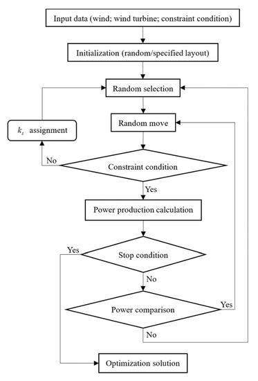
Figure 1.
Flowchart of the optimization methodology.
Specifically, for a wind farm with a rectangular boundary, a method can be introduced to generate a uniform layout. First, the turbines are uniformly arranged on the upwind boundary with maximal density in line. Then, other turbines are arranged row by row with uniform space.
3. Layout Optimization of a Modular Floating Wind Farm
3.1. Structural Module
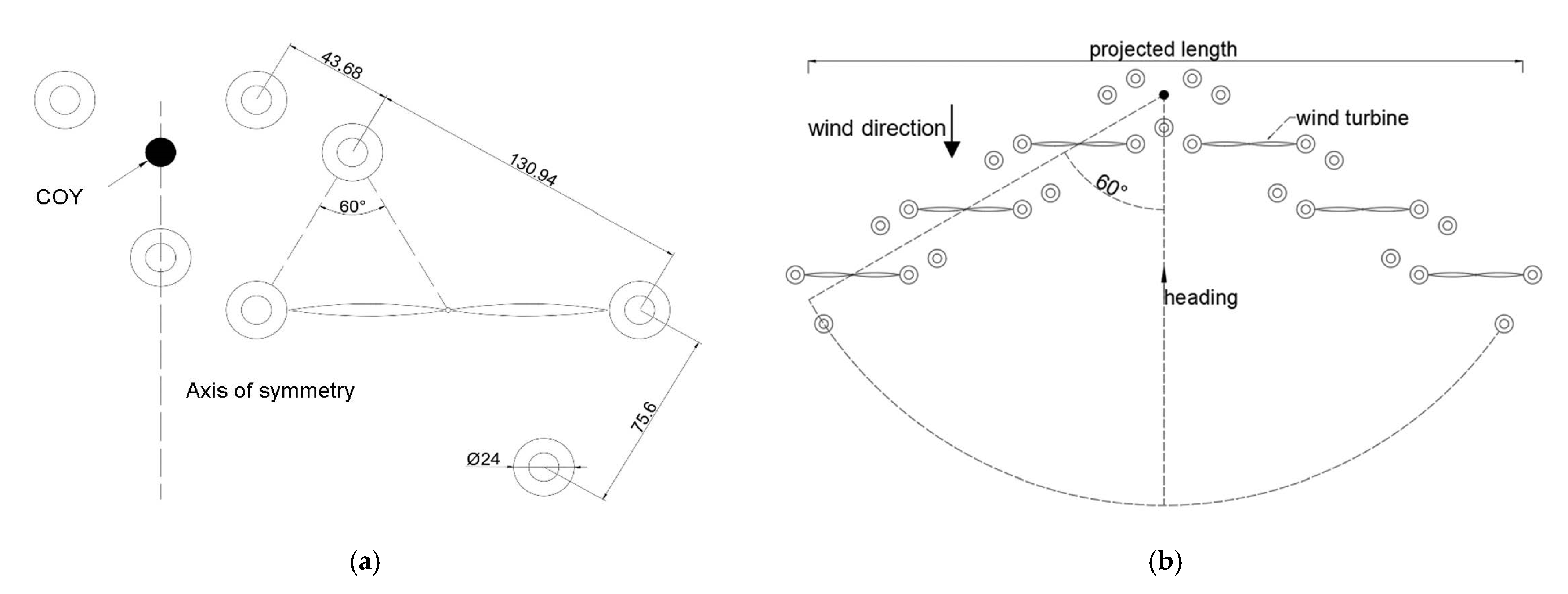
The methodology of layout optimization is applied to an offshore floating wind farm, composed of the structural modules proposed by Zhang and Liu [26]. A sketch of the module is shown in Figure 2. The structure of the platform has arrow-shaped axisymmetric arms. An arrow-shaped layout of wind turbines is adopted on the module with the center of yawing (COY) on a module without a turbine. The platform, as illustrated in Figure 2b, is able to adjust its heading toward the wind direction, i.e., possesses the self-adaptive property, because of this unique configuration. The classical NREL 5 MW wind turbine [28] is adopted on the module. The number of the turbine modules can be varied according to the demand.

Figure 2.
Dimension of the module and platform: (a) the module; (b) the six-turbine platform (top view, m).
3.2. Problem Description
An offshore wind farm with a rectangular boundary is postulated to arrange the floating platforms. The side of the wind farm is 49 × 35D. The area of the wind farm can accommodate 48 wind turbines with a uniform layout of 7, which is common for offshore wind farms [29,30]. To assess the flexibility of the proposed methodology, modular floating platforms with different numbers of wind turbines are considered in the following analytical cases.
At first, the platforms with six wind turbines are adopted to investigate the optimal layout and maximal power output of the wind farm. The total number of turbines in the wind farm are variable, from 48 to 180. In other words, the number of the platforms in the wind farm varies from 8 to 30. Then, the platforms with eight wind turbines are arranged in the wind farm. The layouts with a total of 48, 72 and 96 turbines, i.e., 6, 9 and 12 platforms, respectively, are optimized. A summary is listed in Table 2.
Table 2.
Summary of analytical cases.
All the platforms in the wind farm are assumed to yaw synchronously with the same angle. Thus, the minimal distance of the platform is set to 1.05 times of the projected length, as illustrated in Figure 2b.
A steady uniform inflow wind is considered. The necessary input parameters can be found in Table 3.
Table 3.
Parameters for optimization.
The densities of the wind farms with 16 to 30 six-turbine platforms and 12 eight-turbine platforms are large. These cases cannot be initialized by a random number to form a feasible layout within an acceptable time. Therefore, they are initialized by the uniform layout using the method introduced above. All other cases are initialized by a random layout.
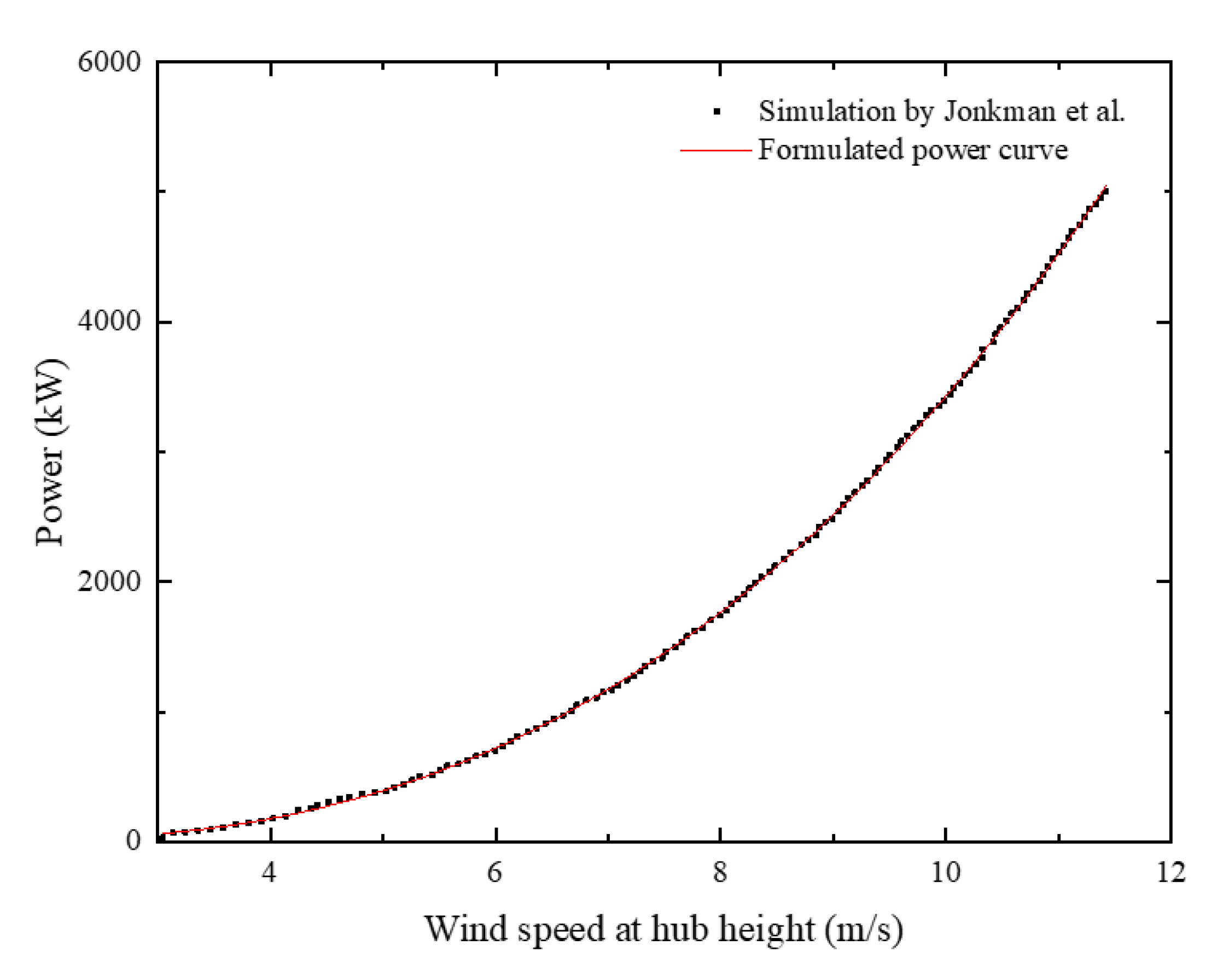
The power curve of the NREL 5 MW wind turbine [28], which was obtained by the CFD simulation of Jonkman et al. [28], is fitted by a cubic polynomial with a mean relative error of 2.1%, as shown in Figure 3. Therefore, as a function of wind speed, the power output of a NREL 5 MW wind turbine is formulated by:
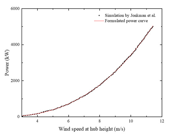
Figure 3.
Power curve of the NREL 5 MW wind turbine.
Each presented optimization result, calculated by the proposed methodology, is the best in 100 optimizations with 100,000 iterations. The optimization methodology is developed in the MATLAB and runs in parallel in a PC with Intel Core i5-9400 CPU 2.90 GHz with six cores and 16 GB RAM. About 50 h are needed to complete all cases.
4. Results and Discussion
Applying the parameters in Table 3, the layouts are optimized following the procedure in Figure 1. The cases are initialized by random layouts for the six-turbine platforms from 8 to 15 and the eight-turbine platforms from 6 and 9. The other cases are initialized by the specified layouts using the method introduced above. The power production is calculated by the full-field wake model and Equation (12).
4.1. Optimization of Six-Turbine Platforms
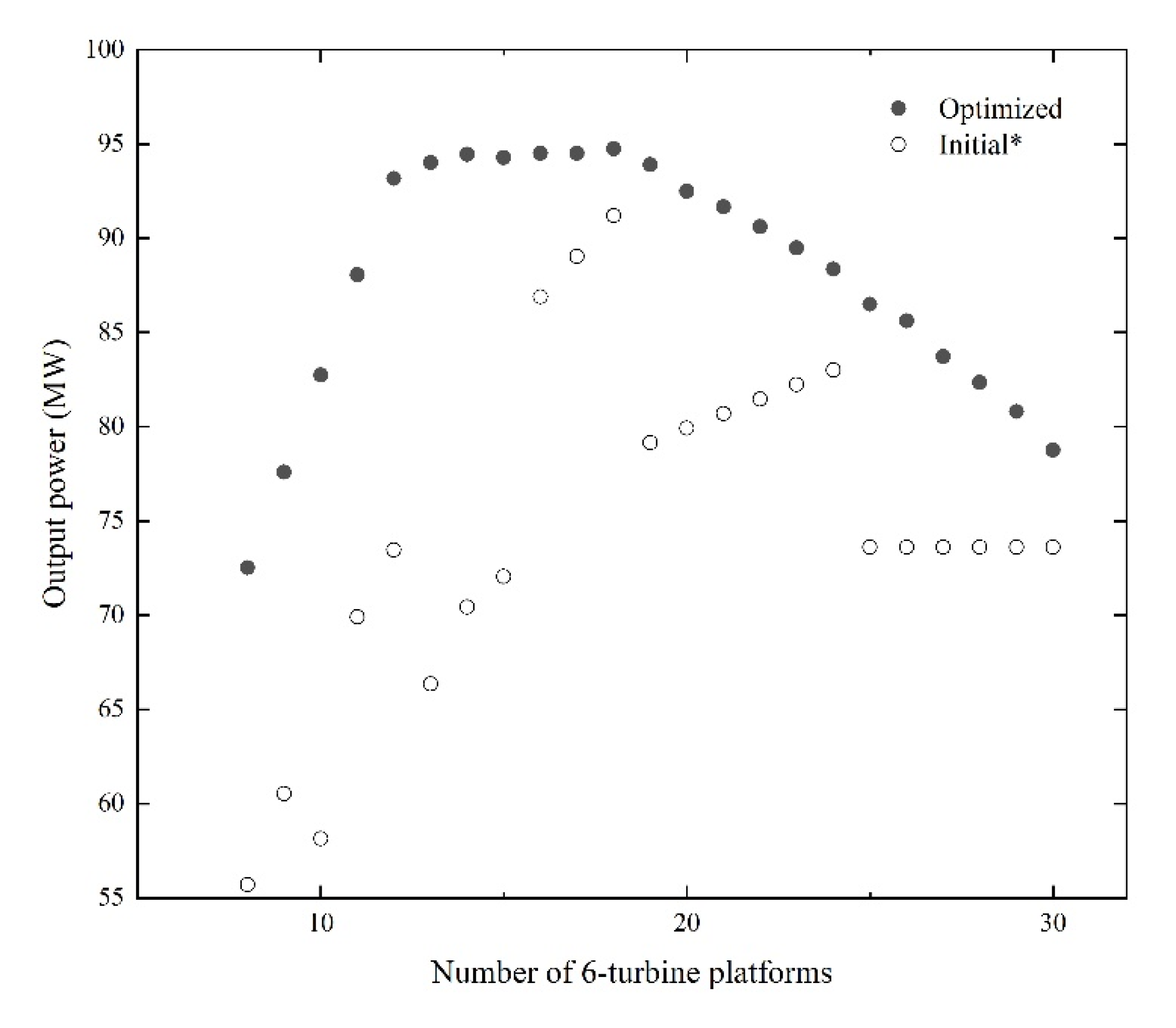
The power productions of each optimized layout from 8 to 30 six-turbine platforms are presented in black points in Figure 4. The power outputs of each initial layout are also presented in white points. Obviously, the production of every initial layout is improved after optimization. The results show good performance of the optimization methodology.
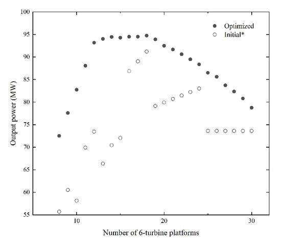
Figure 4.
Output powers of optimized and initial layouts. * Power productions of the initial layouts from 8 to 15 platforms are the power after one iteration step.
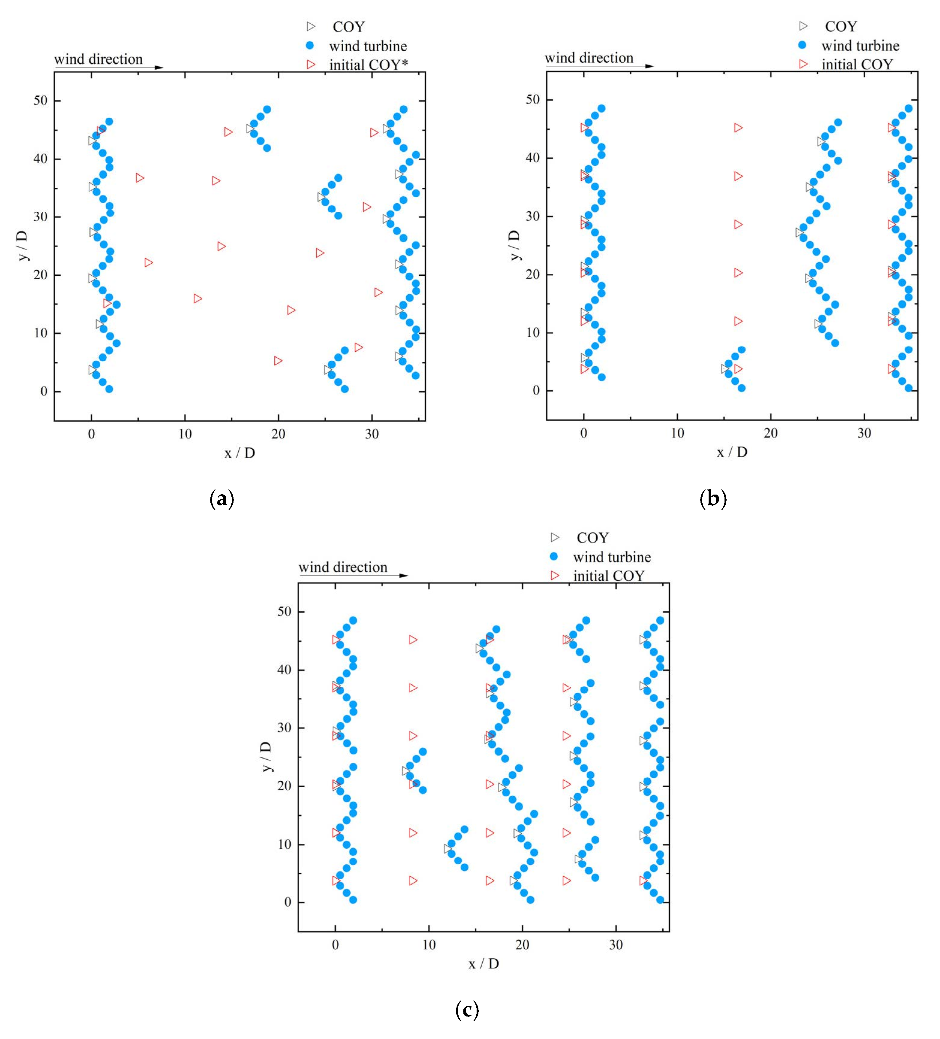
As shown in Figure 4, the optimized power output has a rapid increase at the first, then a very slow increase, and a decrease at last, with increasing number of platforms. The maximal number of platforms in the cross-wind direction is six in a row. The wind turbine wakes of added downwind platforms will not affect other platforms until the number of platforms is 12, as shown in Figure 5. The output power of every added platform is directly counted in the total output power of the wind farm before 12 platforms. Therefore, the optimized output power has a fast linear increase between 8 and 12 platforms. When the number of platforms is between 13 and 18 in the wind farm, the platforms cannot be arranged in only two rows in the cross-wind direction, as illustrated in Figure 6a,b. Downstream wind turbines are affected by the wakes of two upstream wind turbines at most. With an increasing number of wind turbines, more turbines generate power while more turbines are in the wakes of other upstream turbines. A very slow increase of output power in this section means the increase is nearly counteracted by the deficit. When the number of platforms is larger than 18, more wind turbines are in the wakes of multiple upstream turbines, as illustrated in Figure 6c. The power production begins to decrease with the increase of platforms, meaning that the deficit becomes the dominating effect. Even with a special uniform initialization, all initial layouts have room to improve the wind resource utilization. However, obviously, there are more potentials in the sparse layouts. The proposed methodology has indeed the ability to tap these potentials.
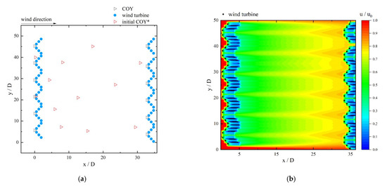
Figure 5.
Optimized layout of 12 six-turbine platforms: (a) position of the platforms; (b) distribution of the velocity. * Not the initialization of the shown optimization, just to illustrate the way of random initialization.
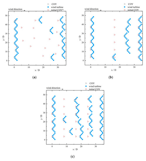
Figure 6.
Optimized layout of six-turbine platforms: (a) 15 platforms; (b) 18 platforms; (c) 25 platforms. * Not the initialization of the shown optimization, just to illustrate the way of random initialization.
Compared with the optimized outputs between 8 and 12 platforms, the power outputs of uniform layouts show a similar increasing way. With increasing turbines of the last row, as shown in Figure 6b,c, the power outputs of uniform layouts also increase linearly. However, the increase slows down with the increase of rows. At last, in the fifth row, the added platforms cannot output any power, meaning that the inflow velocity of the last row is smaller than the cut-in wind speed of the turbine because of strong wake effects.
From 12 to 18 platforms, the number of wind turbines increases by 36, which is half of 12 platforms. More turbines and platforms mean higher cost, because of increased building cost and maintenance cost. When the number of platforms is 18, the output power is the largest. However, the increase of output power is not significant from 12 to 18 platforms, only 1.7%. Obviously, the increased profit is far less than the increased cost. Therefore, in consideration of both production and cost, the optimized layout of 12 platforms, as illustrated in Figure 5, is probably the optimal layout of this wind farm in all cases.
The wake velocity of wind turbines will recover with increased distance from the turbine, as illustrated in Figure 5b. Therefore, the downstream wind turbines can generate more power if they are farther away from the upstream wind turbines in the wind direction or not in the wakes of upstream turbines in the cross-wind direction. The two phenomena can be observed in the optimized layout of 12 platforms (Figure 5). Because of the fixed wind direction, the distance between upstream and downstream turbines reaches the maximum value allowed in the wind farm. The majority of downstream turbines are not right behind the upstream turbines as well. However, the situation is more complex with increased number of turbines. As shown in Figure 6, the optimized layouts of the platforms from 15 to 25 are complicated especially for the middle platforms. Most downstream turbines are still not directly behind the upstream turbines. However, the position of the middle platforms is complex in the wind direction. This illustrates the necessity of layout optimization for a wind farm. The optimal layout cannot be derived easily from the experience especially for a wind farm with lots of wind turbines and various wind directions. With the help of an optimization methodology, the result can be obtained just in a few minutes.
As shown in Figure 5 and Figure 6, most of the platforms arrange in line in the crosswind direction and reach the constraint condition of minimal distance after the layout optimization. This configuration can make the power output of the upstream turbines as large as possible. The wind direction directly determines the direction of turbine wakes. The wakes are also affected by the wind velocity and the turbulence intensity. Furthermore, the number of platforms in a line is limited by the minimal distance of the platform. As a result, different optimized layouts are probably obtained under different wind conditions and constraints of the minimal distance.
4.2. Optimization of Eight-Turbine Platforms
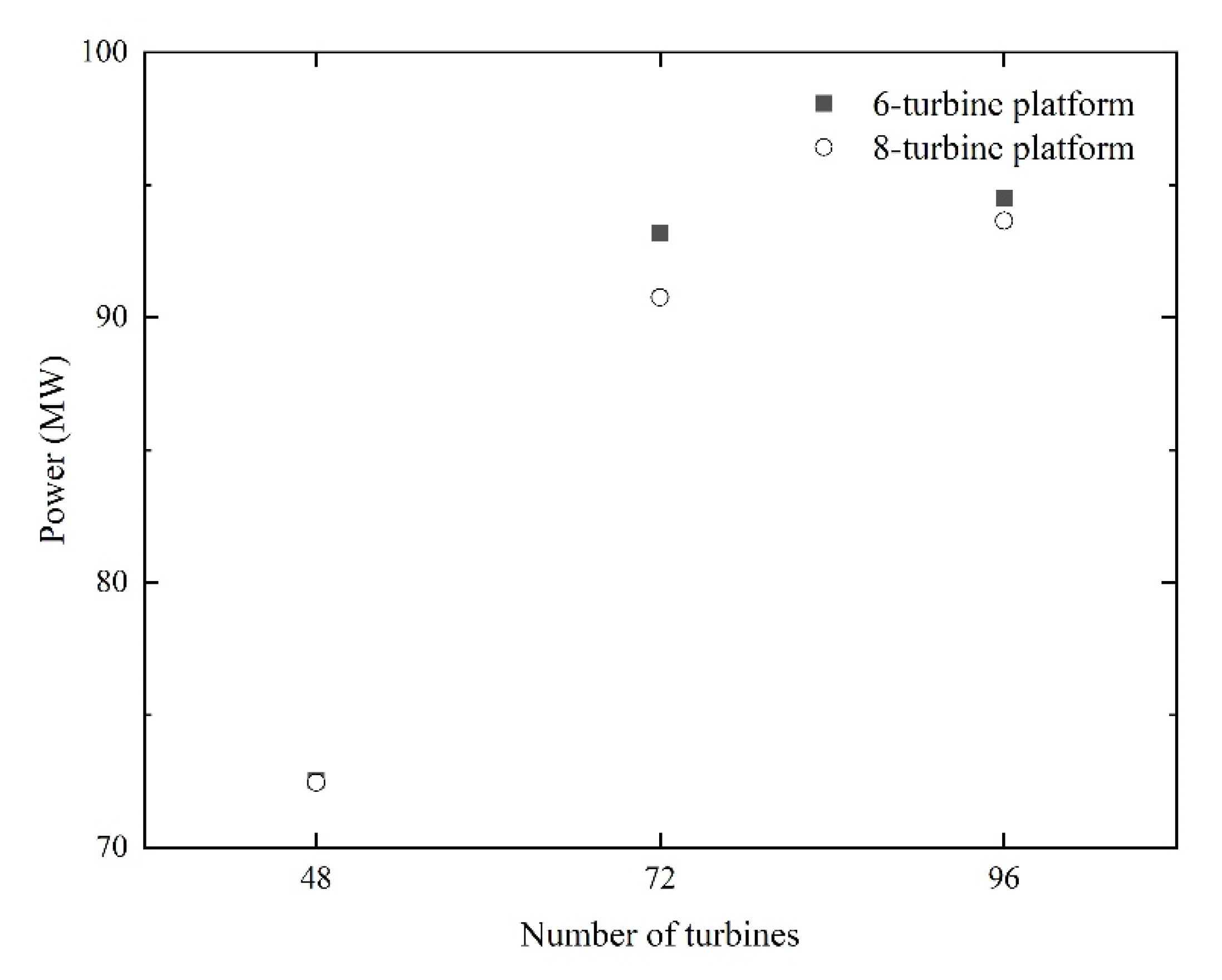
The layout of the wind farm adopting the eight-turbine platforms with 48, 72 and 96 wind turbines is also optimized respectively. Figure 7 and Table 4 present the power output of optimized layouts. It can be observed that the output power of all cases with six-turbine platforms is larger than that with eight-turbine platforms. The eight-turbine platform has a bigger size because it has more wind turbines. This means that there are fewer eight-turbine platforms, which can be arranged in a line in the cross-wind direction, than six-turbine platforms in the wind farm. The difference is four wind turbines. In the situation with the same total number of wind turbines, the wind farm adopting eight-turbine platforms has more turbines in the wakes than the wind farm adopting six-turbine platforms. Therefore, the wind farm with eight-turbine platforms has lower power production.

Figure 7.
Power production of optimized layouts.
Table 4.
Optimized power of two kinds of platforms.
As shown in Table 4 and Figure 7, the optimization has different appearances for different types of platform, although the total number of turbines is identical in the wind farm. In addition, different types of wind turbines, which have different hub heights, rotor diameters, ratings, etc., will generate different wakes. Therefore, different optimized layouts are probably obtained due to these differences.
4.3. Comparison of Algorithms
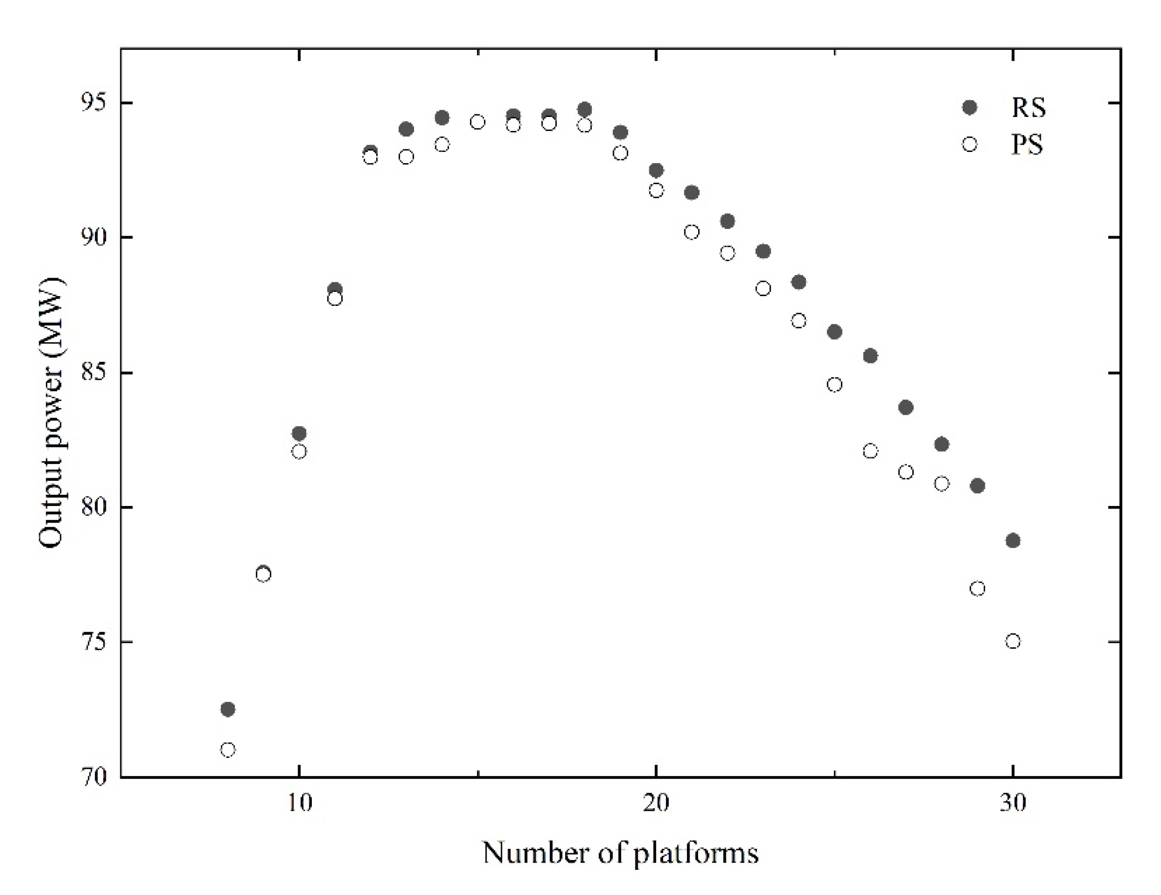
The pattern search algorithm is also adopted for comparison. The same method of initialization is used. As shown in Figure 8, the performance of the RS algorithm is better in all cases. A similar conclusion was obtained by Brogna et al. [27]. However, the difference is not significant especially when there are few platforms. The time cost of the PS algorithm is lower. However, the iteration steps of the RS algorithm can be reduced for some cases. As shown in Figure 9, the RS algorithm can converge within 100,000 iteration steps.

Figure 8.
Optimized power from random search (RS) and pattern search (PS) algorithms.
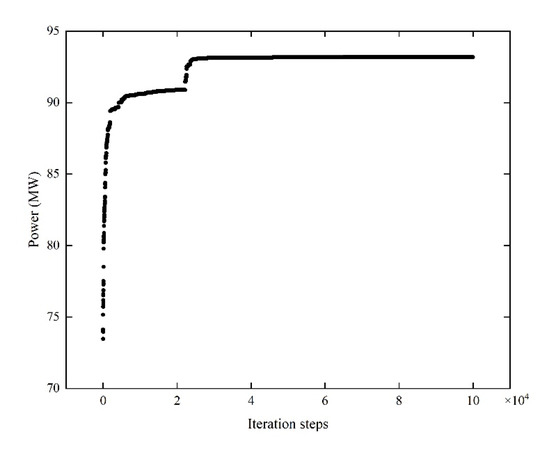
Figure 9.
Iteration history of the optimization for 12 six-turbine platforms.
Each optimization of each case costs no more than a few minutes with the optimization methodology above. The high efficiency of the methodology relies on two aspects. On the one hand, the analytical wake model is an efficient model for optimization. During a layout optimization, hundreds of thousands of layouts need to be analyzed by the wake model to calculate the power production. Every power production value can be calculated for no more than a second with the full-field wake model. This is a huge advantage of the analytical wake model that the numerical simulation method cannot achieve. On the other hand, an efficient optimization algorithm is indispensable. With the original RS algorithm, finding just a few feasible layouts will take 20 h, or even longer, especially for the cases with more than 100 wind turbines in the wind farm investigated above. With the help of the scale factor, , the optimization can be completed in several minutes. Compared with the PS algorithm, the performance of the improved RS algorithm is still good.
5. Conclusions
In the present work, a methodology is proposed to optimize the wind farm layout aiming at maximizing the power production, by considering the wake effects based on the full-field wake model and implementing the improved RS algorithm. The number of wind turbines in the optimized wind farm can be fixed or variable within a range. The initial layout, including a random layout or a uniform layout generated automatically, or a specified layout, which must match the constraint conditions, are all allowable.
The present methodology is applied to an offshore floating wind farm composed of novel structural modules. The analyses demonstrate the outperformance of the methodology, and the efficiency of the improved RS algorithm is also validated. The methodology presents the ability to optimize the layout of modular wind farms, even a crowded layout, with low computational cost. The introduced scale factor significantly improves the applicability and efficiency of the RS algorithm, especially for high-density layouts.
The application results demonstrate that there is an optimal number of wind turbines in a wind farm with maximal power production. Furthermore, the larger modular platform is probably not the better choice in an offshore wind farm, because of bigger size taking up more space with lower output. The optimized layout is complex especially for a high-density layout. The optimal layout cannot be derived easily from the experience, and various wind directions will make the problem more complicated. This highlights the necessity of the layout optimization for a wind farm. With the help of an optimization methodology, the result can be obtained in just a few minutes. It should be noted that the result after optimization is the layout with the maximal output power of the wind farm with a certain number of wind turbines. However, this layout is probably not the real optimal layout, which should be determined in consideration of both production and cost.
During a layout optimization, hundreds of thousands of power productions of a layout need to be calculated over and over again. The surface of the optimization problem is a function problem to find the extreme value. The optimization algorithm provides an efficient way to solve the problem. On the other hand, the root of the problem is a complicated wake effect problem. An accurate, efficient and convenient wake model, to analyze the wake effects inside the wind farm, is the key to ensure the success of the optimization procedure.
In general, the development of the present optimization methodology relies on the improvement of the optimization algorithm and the wake model. Some emerging problems in the present work, such as the convergence judgment of the algorithm during iteration, and the continuously variable wind conditions, will be further investigated in the future.
Author Contributions
Conceptualization, H.L.; methodology, Z.L. and H.L.; formal analysis, Z.L.; writing—original draft preparation, Z.L.; writing—review and editing, H.L.; supervision, H.L. All authors have read and agreed to the published version of the manuscript.
Funding
Financial support from the National Natural Science Foundation of China (Grant no. 51539008).
Institutional Review Board Statement
Not applicable.
Informed Consent Statement
Not applicable.
Data Availability Statement
Not applicable.
Conflicts of Interest
The authors declare no conflict of interest.
Nomenclature
| a | induction factor (dimensionless) |
| Ct | thrust coefficient (dimensionless) |
| D | rotor diameter (m) |
| dis | axial distance from the wind turbine to divide the near and far fields (m) |
| dmin | minimal distance between wind turbines or platforms (m) |
| dx | axial distance of the target point from the wind turbine (m) |
| H | hub height of the wind turbine (m) |
| I0 | freestream turbulence intensity (dimensionless) |
| krand | random number (dimensionless) |
| ks | scale factor (dimensionless) |
| Lmax | length of the long edge of the wind farm (m) |
| n | number of the wind turbines affecting the target point (dimensionless) |
| ns | number of steps of the infeasible random move before a feasible move (dimensionless) |
| nwt | total number of turbines in the wind farm (dimensionless) |
| P | power production of the wind turbine (kW) |
| Psum | power production of the wind farm (kW) |
| r | distance between the calculated point and the rotor shaft of the wind turbine in the radial direction (m) |
| rd | wake radius at d x (m) |
| ris | radial distance of the intersection (m) |
| ΔS | distance of a random move (m) |
| u | wake velocity of the calculated point (m/s) |
| u0 | freestream velocity (m/s) |
| x, y | wind turbine position in the wind direction & cross-wind direction, respectively (m) |
| z0 | surface roughness height (m) |
| Subscripts | |
| i, j | variables of the points or turbines i and j, respectively |
| m, * | variables after modification and before modification, respectively |
References
- Lee, J.; Zhao, F. Global Wind Report 2021; Global Wind Energy Council: Brussels, Belgium, 2021. [Google Scholar]
- Burton, T.; Jenkins, N.; Sharpe, D.; Bossanyi, E. Wind Energy Handbook, 2nd ed.; John Wiley & Sons: Chichester, UK, 2011; p. 619. [Google Scholar]
- Jensen, N.O. A Note on Wind Generator Interaction; Risø-M-2411; Risø National Laboratory: Roskilde, Denmark, 1983. [Google Scholar]
- Katic, I.; Højstrup, J.; Jensen, N.O. A Simple Model for Cluster Efficiency. In Proceedings of the European Wind Energy Association Conference and Exhibition, Rome, Italy, 7–9 October 1986. [Google Scholar]
- Porté-Agel, F.; Bastankhah, M.; Shamsoddin, S. Wind-Turbine and Wind-Farm Flows: A Review. Bound-Lay. Meteorol. 2020, 174, 1–59. [Google Scholar] [CrossRef] [PubMed] [Green Version]
- Larsen, G.C.; Højstrup, J.; Madsen, H.A. Wind fields in wakes. In Proceedings of the 1996 European Union Wind Energy Conference, Göteborg, Sweden, 20–24 May 1996. [Google Scholar]
- Frandsen, S.; Barthelmie, R.; Pryor, S.; Rathmann, O.; Larsen, S.; Højstrup, J.; Thøgersen, M. Analytical modelling of wind speed deficit in large offshore wind farms. Wind Energy 2006, 9, 39–53. [Google Scholar] [CrossRef]
- Bastankhah, M.; Porté-Agel, F. A new analytical model for wind-turbine wakes. Renew. Energy 2014, 70, 116–123. [Google Scholar] [CrossRef]
- Tian, L.; Zhu, W.; Shen, W.; Zhao, N.; Shen, Z. Development and validation of a new two-dimensional wake model for wind turbine wakes. J. Wind Eng. Ind. Aerodyn. 2015, 137, 90–99. [Google Scholar] [CrossRef] [Green Version]
- Zhang, Z.; Huang, P.; Sun, H. A Novel Analytical Wake Model with a Cosine-Shaped Velocity Deficit. Energies 2020, 13, 3353. [Google Scholar] [CrossRef]
- Liu, H.; Fu, J.; Liang, Z.; Zhang, Y.; Liang, Z.; Xiao, Z. A simple method of fast evaluating full-field wake velocities for arbitrary wind turbine arrays on complex terrains. Renew. Energy 2021. submitted. [Google Scholar]
- Mosetti, G.; Poloni, C.; Diviacco, B. Optimization of wind turbine positioning in large windfarms by means of a genetic algorithm. J. Wind. Eng. Ind. Aerodyn. 1994, 51, 105–116. [Google Scholar] [CrossRef]
- Beyer, H.G.; Rüger, T.; Schäfer, G.; Waldl, H.P. Optimization of wind farm configurations with variable number of turbines. In Proceedings of the European Union Wind Energy Conference, Göteborg, Sweden, 20–24 May 1996. [Google Scholar]
- Grady, S.A.; Hussaini, M.Y.; Abdullah, M.M. Placement of wind turbines using genetic algorithms. Renew. Energy 2005, 30, 259–270. [Google Scholar] [CrossRef]
- Feng, J.; Shen, W.Z. Optimization of Wind Farm Layout: A Refinement Method by Random Search. In Proceedings of the 2013 International Conference on aerodynamics of Offshore Wind Energy Systems and wakes, Lyngby, Denmark, 17–19 June 2013. [Google Scholar]
- Feng, J.; Shen, W.Z. Solving the wind farm layout optimization problem using random search algorithm. Renew. Energy 2015, 78, 182–192. [Google Scholar] [CrossRef]
- Feng, J.; Shen, W.Z. Co-optimization of the shape, orientation and layout of offshore wind farms. J. Phys. Conf. Ser. 2020, 1618, 42023. [Google Scholar] [CrossRef]
- Hwang, B.; Kim, H.; Lee, S. Wind farm layout optimization using multidisciplinary model. J. Mech. Sci. Technol. 2018, 32, 2919–2924. [Google Scholar] [CrossRef]
- Kirchner-Bossi, N.; Porté-Agel, F. Realistic Wind Farm Layout Optimization through Genetic Algorithms Using a Gaussian Wake Model. Energies 2018, 11, 3268. [Google Scholar] [CrossRef] [Green Version]
- Farajifijani, R.; Ahmadian, S.; Ebrahimi, S.; Ghotbi, E. Wind Farm Layout Optimization Problem Using Joint Probability Distribution of CVaR Analysis. In Proceedings of the 2019 IEEE 9th Annual Computing and Communication Workshop and Conference, Las Vegas, NV, USA, 7–9 January 2019; pp. 7–12. [Google Scholar]
- Zhang, J.; Jiang, Y. Joint optimization of the number, type and layout of wind turbines for a new offshore wind farm. J. Renew. Sustain. Energy 2020, 12, 053308. [Google Scholar] [CrossRef]
- Shin, J.; Baek, S.; Rhee, Y. Wind Farm Layout Optimization Using a Metamodel and EA/PSO Algorithm in Korea Offshore. Energies 2021, 14, 146. [Google Scholar] [CrossRef]
- Gonzalez-Rodriguez, A.G.; Serrano-González, J.; Burgos-Payán, M.; Riquelme-Santos, J.M. Realistic Optimization of Parallelogram-Shaped Offshore Wind Farms Considering Continuously Distributed Wind Resources. Energies 2021, 14, 2895. [Google Scholar] [CrossRef]
- Kheirabadi, A.C.; Nagamune, R. Modeling and Power Optimization of Floating Offshore Wind Farms with Yaw and Induction-based Turbine Repositioning. In Proceedings of the 2019 American Control Conference, Philadelphia, PA, USA, 10–12 July 2019; pp. 5458–5463. [Google Scholar]
- Serrano González, J.; Burgos Payán, M.; Riquelme Santos, J.M.; González Rodríguez, Á.G. Optimal Micro-Siting of Weathervaning Floating Wind Turbines. Energies 2021, 14, 886. [Google Scholar] [CrossRef]
- Zhang, Y.; Liu, H. A Novel Structural Configuration of Modular Floating Wind Farms with Self-Adaptive Property. J. Offshore Mech. Arct. Eng. 2021, 143, 052002. [Google Scholar] [CrossRef]
- Brogna, R.; Feng, J.; Sørensen, J.N.; Shen, W.Z.; Porté-Agel, F. A new wake model and comparison of eight algorithms for layout optimization of wind farms in complex terrain. Appl. Energy 2020, 259, 114189. [Google Scholar] [CrossRef]
- Jonkman, J.; Butterfield, S.; Musial, W.; Scott, G. Definition of a 5-MW Reference Wind Turbine for Offshore System Development; NREL/TP-500-38060; National Renewable Energy Laboratory: Golden, CO, USA, 2009.
- Hansen, K.S.; Barthelmie, R.J.; Jensen, L.E.; Sommer, A. The impact of turbulence intensity and atmospheric stability on power deficits due to wind turbine wakes at Horns Rev wind farm. Wind Energy 2012, 15, 183–196. [Google Scholar] [CrossRef] [Green Version]
- Westerhellweg, A.; Cañadillas, B.; Kinder, F.; Neumann, T. Wake Measurements at alpha ventus—Dependency on Stability and Turbulence Intensity. J. Phys. Conf. Ser. 2014, 555, 12106. [Google Scholar] [CrossRef] [Green Version]


Publisher’s Note: MDPI stays neutral with regard to jurisdictional claims in published maps and institutional affiliations. |
© 2022 by the authors. Licensee MDPI, Basel, Switzerland. This article is an open access article distributed under the terms and conditions of the Creative Commons Attribution (CC BY) license (https://creativecommons.org/licenses/by/4.0/).