Abstract
Building envelopes can manage light, heat gains or losses, and ventilation and, as such, play a key role in the overall building performance. Research has been focusing on increasing their efficiency by proposing dynamic and adaptive systems, meaning that they evolve to best meet the internal and external varying conditions. Living organisms are relevant examples of adaptability as they have evolved, facing extreme conditions while maintaining stable internal conditions for survival. From a framework based on the inspiration of living envelopes such as animal constructions or biological skins, the concept of an adaptive envelope inspired by the Morpho butterfly was proposed. The system can manage heat, air, and light transfers going through the building and includes adaptive elements with absorption coefficients varying with temperature. This paper presents the developed framework that led to the final concept as well as the concept implementation and assessment. A prototype for heat and light management was built and integrated into a test bench. Measurements were performed to provide a first assessment of the system. In parallel, geometrical parametric models were created to compare multiple configurations in regards to indicators such as air, light, or heat transfers. One of the models provided light projections on the system that were compared with measurements and validated as suitable inputs in grey-box models for the system characterization.
1. Introduction
Today, challenges in the building sector are mainly focused on reducing energy consumption and greenhouse gas emissions while maintaining indoor environmental quality. Building designs have gradually evolved with technological advances to comply with stiffer requirements in terms of comfort, energy, and durability [1]. The envelope is more than a load-bearing component of the building. As it has a major impact on the whole building energy consumption, it is expected to manage multiple regulation functions between internal and external environments [2].
New generations of envelopes are emerging: dynamic, auto-reactive, and responsive envelopes [3]; all demonstrate adaptability towards changing environmental conditions while ensuring comfort and a low carbon footprint. Adaptive envelopes can provide varying thermal insulation depending on the season, harvest energy, move in accordance with the sun’s path, control humidity, and so on, in a way that could help achieve more sustainable building designs [4].
Mechanisms found in nature reveal inspiring examples of multifunctional envelopes using very limited local resources [5]. Indeed, living species had to evolve under various environmental constraints, requiring them to develop adaptive and multifunctional features. Rising as an innovative approach, bioinspiration in the building field is the topic of extensive research; it mainly focuses on design processes, frameworks, and tools to ease the transfer of biological principles into technological responses [6,7,8]. Some research has already led to several adaptive case studies, but very few propose performance assessments of their design [9].
The current paper presents an adaptive envelope concept derived from a bioinspired framework. The concept, called Stegos, is a heat-, light-, and air-regulating membrane that plays the role of a skin placed in front of an opaque wall or a window or acts as an openable envelope. Stegos was prototyped and tested in real climate conditions. Measurements were carried out to help with modeling and later to retrieve performance indicators.
2. Adaptive Concept Derived from a Bioinspired Framework
In support of bioinspired processes, a multitude of tools or methods were recently developed, such as databases, thesauri, ontologies, or taxonomies, for instance [10]. Tools from other disciplines, such as design reasoning theories in engineering [11,12], can also facilitate the biomimetic process [13] and have already been successfully applied during design processes [14]. However, only a small fraction of patterned bioinspired concepts or products are commercialized [15]. Though this gap is partially due to usual design constraints (feasibility, strategy, marketing, and so on), it is also mostly related to the challenges of transferring information from living organisms to technologies [16].
The transferability of an identified biological strategy into technology is complex without a good understanding of the phenomena at stake in the biological element. Tools to facilitate interdisciplinarity during bio-inspired design are increasingly numerous, but they face limitations as they are frequently designed for and by engineers rather than biologists [17] and often consider a specific objective rather than the full process. The steps of identification and understanding relevant biological models, and then of transferring a biological model to a technological concept, would thus deserve more advanced interdisciplinarity during the design process.
In the building sector, the practice of bioinspiration has led to multiple bioinspired buildings designs, but most of them are monofunctional designs, where the inspiring species demonstrate multifunctional features [8]. The assessment of the building performance is often not carried out, which can be seen as a shortcoming [9]. In an effort to tackle these challenges, the authors experimented with a bioinspired framework [18] that they adapted from an ISO standard design process [19], with the aim of proposing a multifunctional design for the building envelope.
2.1. Biological Envelopes as the Starting Point of the Framework
The ISO standard 18458:2015 provides a framework to help harmonize practices in bioinspiration. Using the biology-push approach, meaning the design process is initiated by one or several biological solutions [20], we propose a four-step process:
- 1: The description of biological models;
- 2: The understanding of their principles;
- 3: Their abstraction into a concept;
- 4: The validation of its technical feasibility, i.e., the transferability to technology or solution and its implementation and assessment.
To narrow down the perimeter of the studied biological domain used in step one, the authors chose to consider living envelopes. Those include the following:
- Biological envelopes that are the interface of living organisms between their internal environment and external conditions (for instance, animal envelopes such as skin, feather, and shells, or vegetal envelopes such as bark);
- Structures built by animals for shelter, rest, storing, or communication [21] (bird nests, colonies, mounds).
This selection was arbitrarily chosen as species have evolved and developed multifunctional interfaces through mutations and selective processes, either on their own or by demonstrating ingenuity and resilience to regulate multiple factors of their internal environments while facing an environment characterized by varying conditions.
Step two of the applied design process involves selecting a sample of living envelopes and characterizing their functions in an intelligible structure for building designers. Based on [22,23], this approach consists of identifying functions as building envelope criteria and describing them as the result of environmental disturbances or disruptive actions, and through physical phenomena. Disturbances from the environment, whether they were nonliving elements (climatic conditions such as rain and wind) or living organisms (metabolism and interaction with other species), were taken into account in the understanding of the biological domain with the support of biologists in adaptive mechanisms [24].
This interdisciplinary work addressed transferability challenges observed in the literature during step three by providing an understanding of living models at the crossroads of biology and engineering. Step three is a series of ideation workshops involving various building sector profiles (engineers, architects, designers) to test this characterization as a tool of abstraction into multifunctional envelope concepts. The last step (step four) consists of transposing concepts into technological alternatives and exploring several of them in their implementation.
The bioinspired concept presented in this article is derived from this framework. We present in the following how it emerged and was conceptualized, designed, and prototyped.
2.2. Morpho-Butterfly-Inspired Design
The design presented here is based on the Morpho butterfly, one of the selected species in the sample of biological models. This animal (from the Class Insect and Order Lepidoptera) is well known for the intense blue of its wings due to the structural properties of scales and not to pigmentation [25]. Table 1 presents the structure of the characterization used for the emerged concept, focusing on two main functionalities: heat and light.

Table 1.
Biotics and abiotic disruptive actions on light, heat, and air regulation functions of the Morpho butterfly.
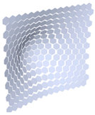
To survive, the Morpho requires a body temperature of 36 °C [27]. Therefore, it has developed multiple behavioral mechanisms for thermoregulation, such as wing shuffling to force convection on the thorax or orienting its wings for minimum or maximum solar radiation. On a morphological level, the chitin-made wings of the Morpho are able to emit more in the near-infrared when reaching a temperature above a certain threshold so that they automatically decrease in temperature and return to optimal conditions. Figure 1 shows the illustration of the concept that emerged during the ideation workshop.
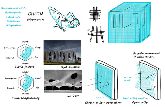
Figure 1.
Proposed concept inspired from the Morpho. Credit: Myriame Ali-Oualla and Kaïs Bhouri.
Abstraction from the ideation phase led to a concept of a membrane, both flexible and ductal, similar to the wings of the Morpho made of chitin polymer. The structure is a deformable mesh made of identical solid elements held together. When the mesh is deformed, the elements are pushed away from each other, creating openings between them. The elements themselves are deployable using flaps that can rotate on a base. The rotation is induced either by the deformation or by a manually operated device. Additional functionality is brought by a coating on the flaps, which has an adaptive absorption coefficient linked to changes in temperature. Table 2 lists the functions managed by this concept in some of the possible configurations.
Table 2.
Managed functions according to configurations. For visual display, flaps are white and base elements are dark grey.
The adaptive properties of this concept were chosen to be both auto-reactive (coating, flaps) and mechanically operated by the building occupants (deformation, flaps).
2.3. Parametric Design of the Concept
As a biology-push approach was followed for the design concept, no particular building envelope requirements were defined as specifications for the final design. However, it had to be multifunctional regarding heat, light, and air management. Once the functions were characterized, considering clear requirements, a specific design could be proposed.
These functions are sometimes implemented through interdependent parameters; as an exploration before a final set of parameters, numerous parameters and their respective values were proposed (Table 3).
Table 3.
List of design parameters that were considered for the concept and their respective possible values.
The functions brought by the different values of the parameters are various. To narrow the study to a limited number of designs, derivatives of the concept were prototyped with the following elements:
- Form of the mesh elements: size, shape, orientation, and the axis of rotation;
- The total scale of the design: minimum size for representative results in terms of the physical phenomena.
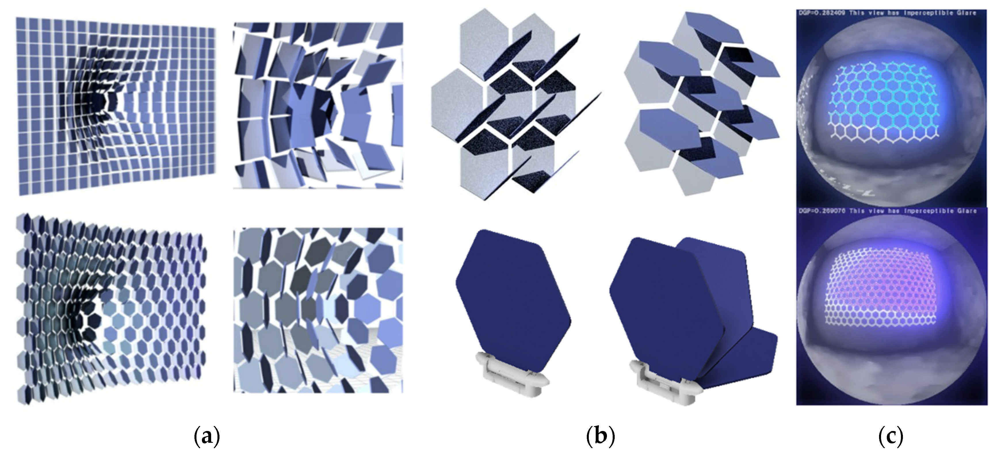
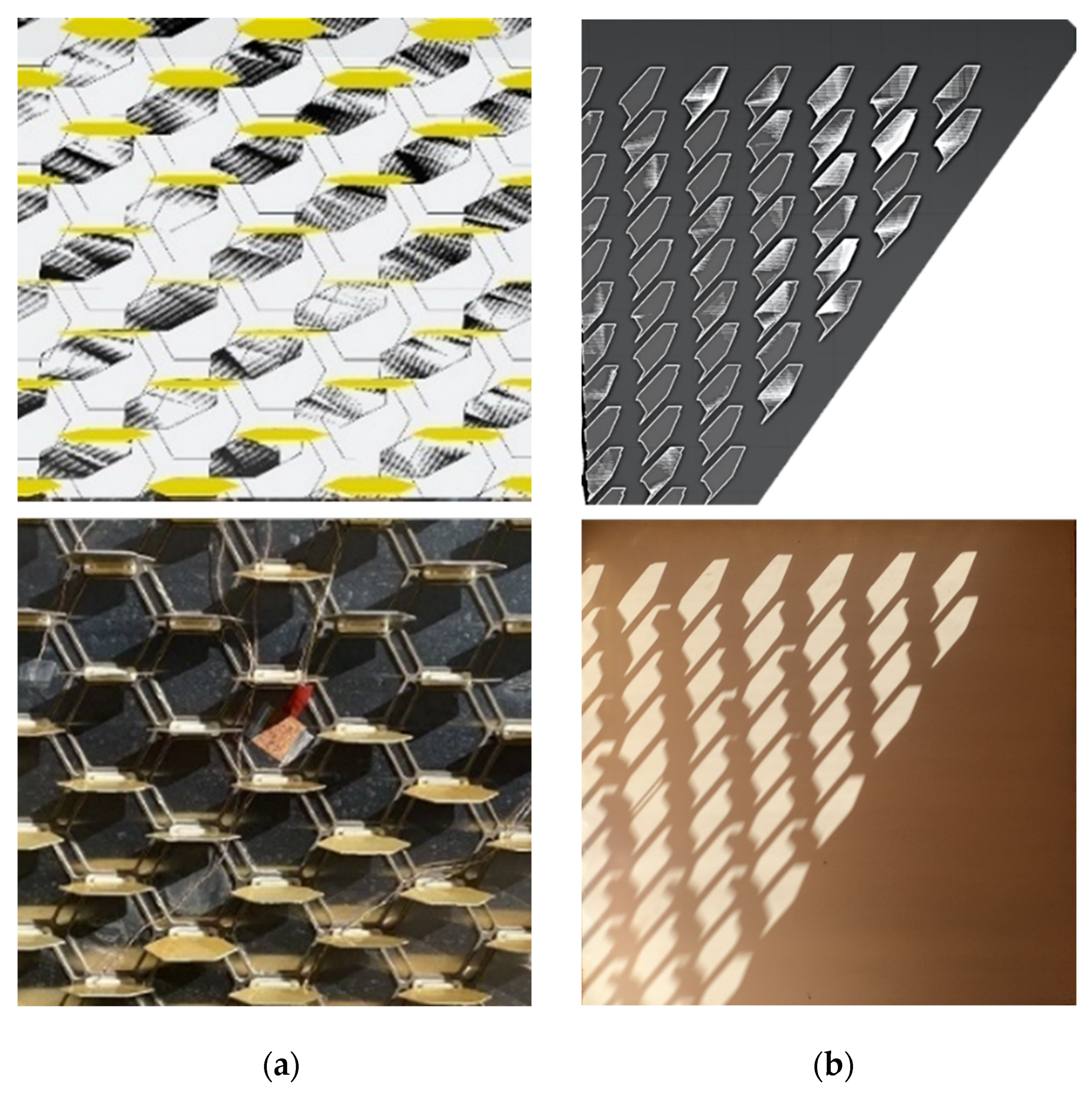
Form-finding and visual representation helped define the form of the mesh elements. The hexagonal shape was chosen over squares as it removed physical collisions between opened flaps when the mesh was deformed, as shown in Figure 2a. Projected light simulations foreshadowed various scenarios when changing the orientation of the flaps along the mesh; hence, this parameter was selected and technically implemented into the prototype by designing a notched system (Figure 2b). Last, the size of the elements was arbitrarily set as a trade-off between the minimum size for ease of manufacture and the maximum acceptable size by the occupants in terms of view towards the exterior environment (Figure 2c).

Figure 2.
All computer-aided images were made using Rhinoceros Grasshopper software. (a) Visual representation of potential collisions during deformations using squares vs. hexagons as base elements. (b) Exploration of different positions of flaps. The interchangeability was kept possible for the prototype using a 3D-printed notch-system as a flap holder, insertable into an aluminum frame as shown in the bottom images. (c) Qualitative determination elements with a fish-eye view from behind glazing. HD file generated using the Ladybug component.
To obtain significant results in terms of physical phenomenon and overpass scale effects, mostly regarding air flows and the edge effect on thermal losses, the total design surface area was set to an arbitrary 1 m2 for the experimentation.
All parameters chosen above are the result of feasibility considerations. They are trade-offs between the time of prototyping, cost, and complexity of construction techniques. The piloting of the flaps, for instance, was chosen to be mechanical, and manually operated.
3. Experimentation on a Prototype: Stegos Design
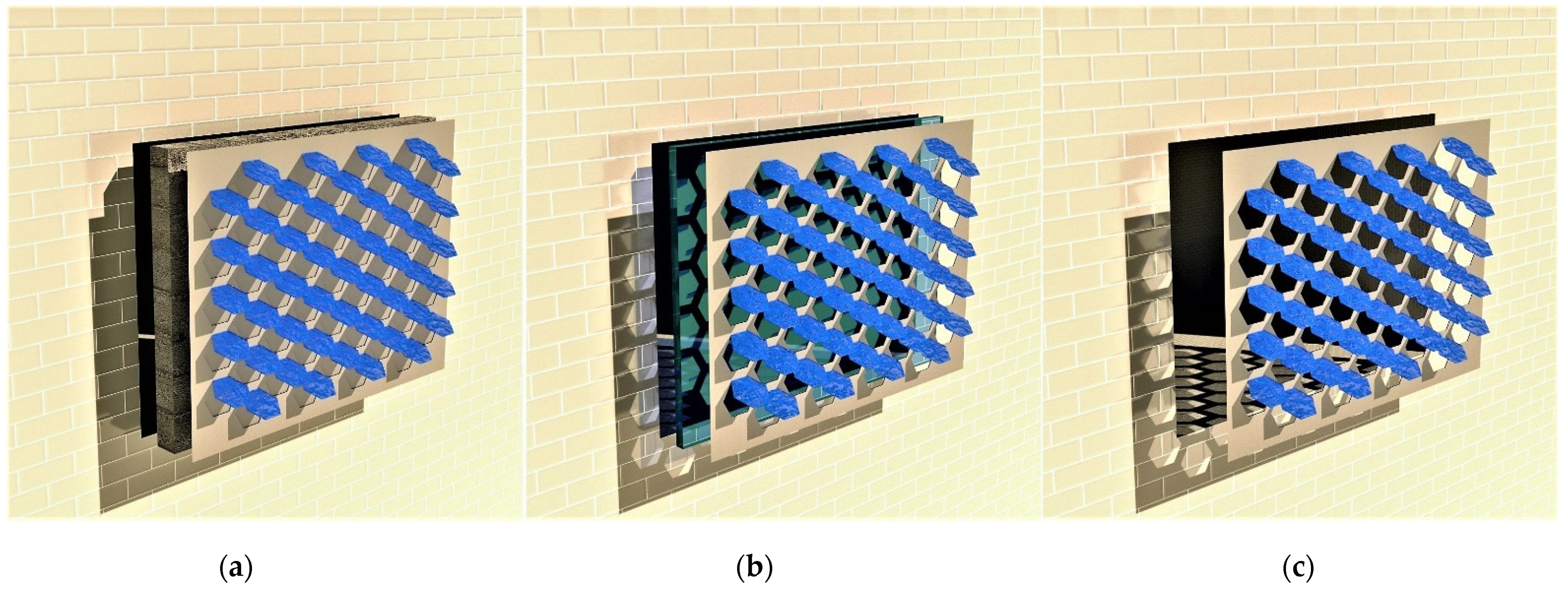
The concept presented in Part 2 combines multiple functions that are co-dependent and rely on a distortion coupled with deployment and auto-reactive paint. To separately assess the contribution of deployment and distortion on the thermal, light, and air properties, the authors prototyped a first version, called Stegos, with only rotating coated flaps. Three possible architectural integration configurations are considered (see Figure 3):
- ‘Opaque’ configuration, as part of an opaque wall;
- ‘Glazing’ configuration, as a smart protection envelope put in front of windows;
- ‘Envelope’ configuration, as an openable envelope, equivalent to a window. Although complex to implement, it would offer multiple regulation assets for warm climates.
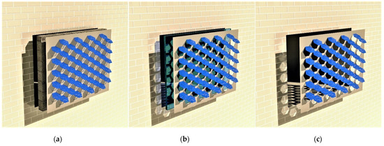
Figure 3.
(a) ‘Opaque’ configuration. (b) ‘Glazing’ configuration. (c) ‘Envelope’ configuration.
Figure 3.
(a) ‘Opaque’ configuration. (b) ‘Glazing’ configuration. (c) ‘Envelope’ configuration.
3.1. Prototyping
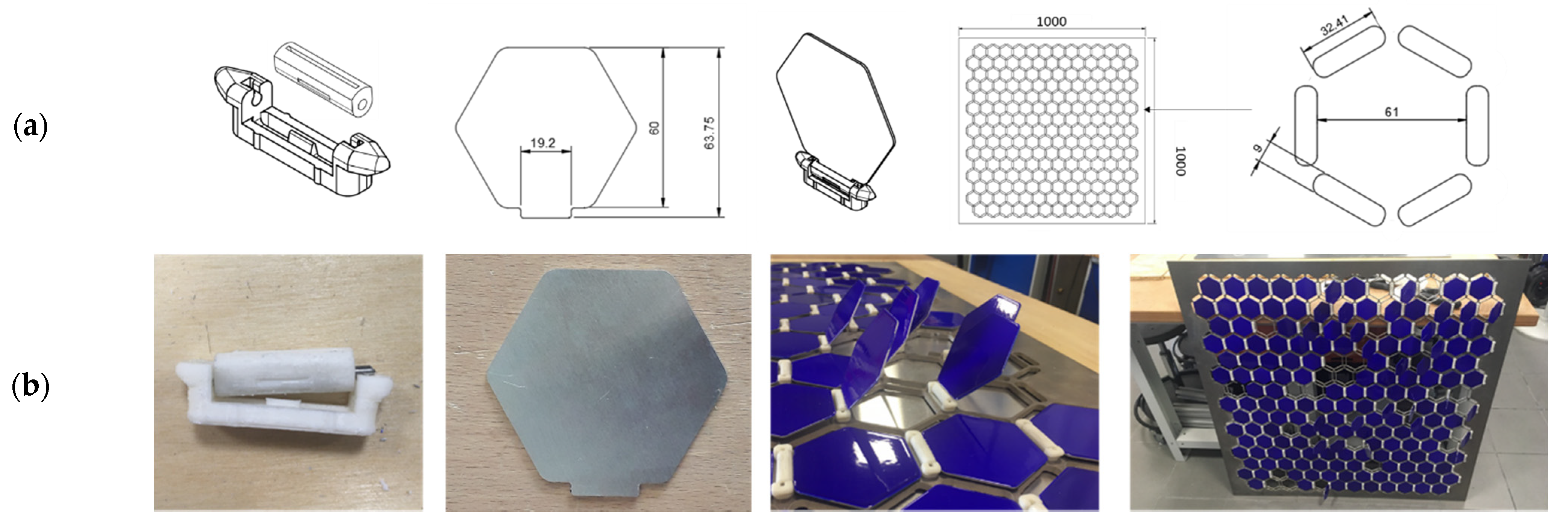
The prototype was manufactured to be modular and easily switched from one configuration (as described in Figure 3) to another. It was designed as an assembly of aluminum pieces and 3D-printed material. Schematics and photos of all pieces are shown in Figure 4.
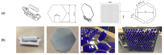
Figure 4.
(a) Schematics of the notched system, flaps, and the aluminum frame. (b) Photographs of the prototype elements.
A 1 m2 aluminum plate, 4 mm thick, was first water-jet cut as a structural support. The cutting included the edges of the frame, hexagonal holes to let light and air go through for the ‘glazing’ and ‘envelope’ configurations, and oval-shaped holes to insert the rotating flap system.
The notch system, designed to change the position and angles of the flaps according to the time of day, season, or year, was 3D-printed with ABS. It is made of two pieces, one for inserting the flaps and a second to be inserted into the aluminum frame. Both of them have ridges to create a controlled manual rotation 15° by 15°, and they are held together with a metal pin. Small edges on the side of the bottom piece ensure a mechanical holding into the aluminum frame.
The flaps were laser-cut into 1 mm thick aluminum plates. An overhang on one side of the hexagonal piece allows insertion into the notched system slit without using screws or glue. They were painted with thermochromic paint, as explained in the next section.
The assembly of these elements forms the ‘glazing’ and ‘envelope‘ Stegos basic configurations. For the ‘opaque’ one, a 1 m2 plain plate of 1 mm thick aluminum was added behind the system.
3.2. Thermochromic Coating
The auto-reactivity of the Stegos, a feature inspired by the emissive properties of the butterfly, was technologically translated using a thermochromic paint, i.e., whose color changes with temperature. Different pairs of colors, such as brown cream or burgundy yellow, were formulated for a temperature threshold around 45 °C, before settling with a blue white combination for the prototype. The reflectance of the thermochromic paint was measured at 20 °C and 60 °C. A spectrophotometer measuring the reflected light (specular and diffuse) was used on samples of coated aluminum plates for a wavelength between 200 nm and 2500 nm. The deduced absorption coefficient (α = 1 − R) is shown in Figure 5. The change in color from blue to white when temperature increases is not instantaneous, but rather progressive between 40 °C and 50 °C.
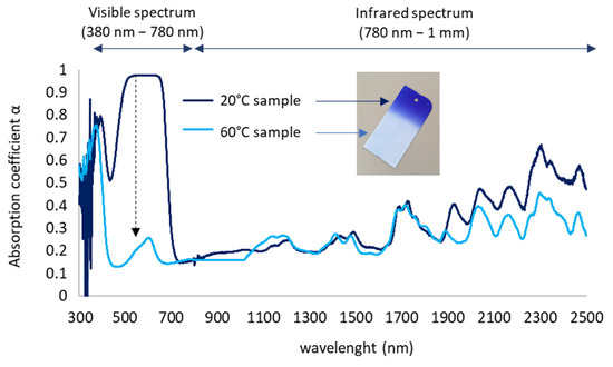
Figure 5.
Absorption coefficient of paint measured at 20 °C and 60 °C. The black arrow on the graph shows a high variation in the coefficient in the visible spectrum.
When changing color from blue to white, the coating absorptivity naturally decreases in the visible spectrum (40% average decrease between 400 nm and 700 nm). As this wavelength range accounts for 40% of the total solar spectrum energy [28], such a change on a thermochromic-coated material should have a significant impact on its solar thermal absorption. The absorption coefficient is lower as well in the near-infrared wavelength range, albeit not as significant. Therefore, when exposed to constant solar radiation, the expected behavior of a coated sample is a slowdown in the increase in temperature around the threshold temperature.
3.3. Integration in Test Box Protocol Experimentation
To observe realistic behavior as a skin, the prototype was integrated into an insulated, airtight box specifically designed for experiments in real climate conditions.
3.3.1. Test Box Design
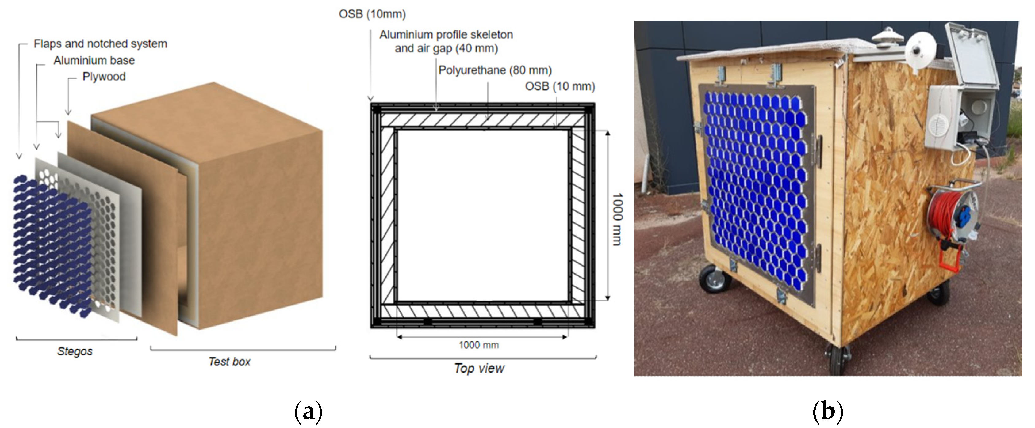
The test box was designed to have an internal exact 1 m3 volume (Figure 6). It was composed of six walls, one of them being interchangeable, i.e., destined for tested system façades. The other five walls were made of 8 cm of polyurethane insulation, sandwiched between oriented strand board (OSB). For structural purposes, aluminum profiles were added on their outer sides between insulation and OSB, adding an air gap of 40 mm.
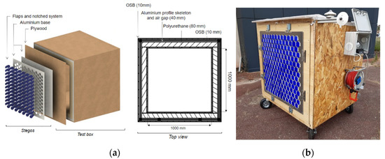
Figure 6.
(a) Diagram of the tests box with the Stegos as an opaque wall. (b) Photograph of the test box with the Stegos integrated on one of the façades.
Several actions were made to avoid deterioration of the box with time owing to humidity or heavy rains while experimentations were ongoing: external OSBs were varnished, the top of the box was covered with a waterproof membrane, and a silicone joint was applied on several points to improve airtightness. A roof overhang was added as well, small enough to not create a shadow on the tested façade that would interfere with the measurements.
To be able to test the box in all orientations and to make it rotative, the test box was equipped with four steering wheels. An electric box with ventilation grids was screwed on one of the external sides to hold the monitoring instruments away from the internal conditions of the test box and protect them from climatic conditions. In fact, the issue of having them inside the box would be non-negligible disturbances on the test box internal conditions owing to generated heat.
The design of the test box allows the experiments of the Stegos in all three configurations, as illustrated in Figure 3. The ‘Glazing’ configuration requires replacing the plywood with a transparent wall (a synthetic glass such as Plexiglas was chosen) airtightly plastered on the test box, on which the Stegos is placed. To switch to the ‘Envelope’ configuration, only removing the transparent layer is needed.
3.3.2. Experimental Protocol
To monitor the weather conditions, sensors for the external air temperature, the wind, and the solar irradiance on planar surfaces were installed. Two configurations’ experiments are presented in this article: the ‘Glazing’ and the ‘Opaque’ configurations for varying angles of rotation of flaps of 0°, 45°, and 90°.
The monitoring of the test box and the Stegos behaviors varied from one configuration to another as their targeted functionalities are different. When the Stegos is used as part of an opaque wall, measurements of temperature and heat-flows were inside the test box and at different layers of the tested façade. The list of all sensors is given in Table 4.
Table 4.
List of installed sensors on the test bench.
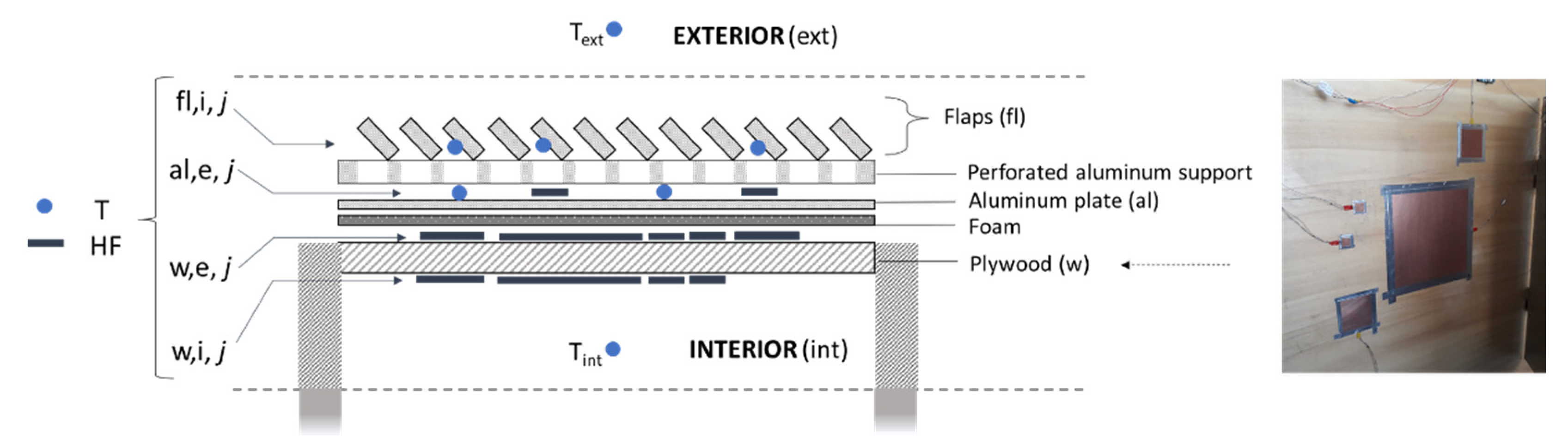
Thermocouple sensors taped on flaps and welded on all heat flux sensors measured surface temperature where heat flows are measured. Copper foil heat flux sensors with tangential gradients of varying sizes (surfaces from 3 mm × 3 mm to 30 mm × 30 mm, thickness of 5 mm) were duplicated on some layers; even though these sensors were all calibrated beforehand, ‘incorrect’ measurements were still possible because of several factors such as an improper set-up of the sensors or unpredictable issues during experimentation. The repartition of the sensors is illustrated in Figure 7. Note that a 5 mm foam was added between the aluminum plate and the plywood to ensure no air gap.
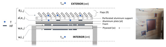
Figure 7.
Repartition and nomenclature of temperature (T) and heat flux (HF) sensors using a top-view diagram of the Stegos + wall of the test box.
To assess the ‘Glazing’ configuration, the shading effect of the Stegos flaps was assessed with a camera fixed inside the test box, looking at the bottom surface in order to take a time-lapse of the projected light and shadow throughout the day.
The testing procedure starts with the installation of the presented test box equipped with the Stegos outside in Talence (close to Bordeaux), France. The typical measurement lasts 3 to 4 days with the objective to have 2 full days. The measurements were carried out between 1 August and 30 November of 2021 with south and south-west orientations and configurations as ‘opaque’ and ‘glazing’. A series of 10 separated sequences were run.
3.4. Measurements
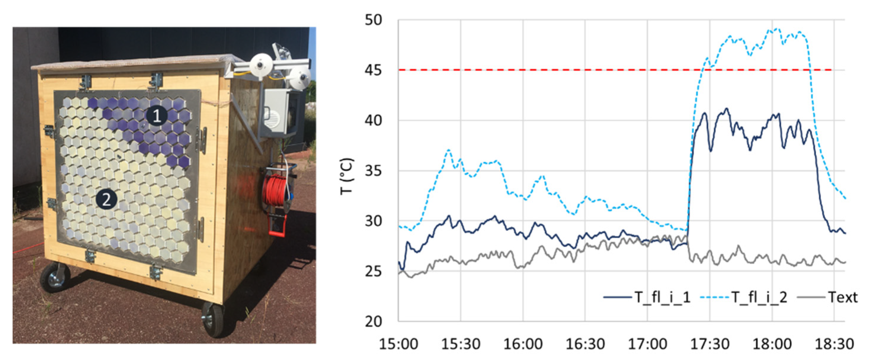
The flaps showed an effective color change when the surface temperature reached a temperature beyond 45 °C (Figure 8). Owing to the use of aluminum as a base material for the flaps, i.e., quite absorptive (see Figure 5) and with high thermal conductivity (λaluminum = 230 W/m·K), a decrease or increase in very short time cycles of the solar radiation—owing to a temporary cloud cover, for instance—had an immediate visual effect on the surface color.
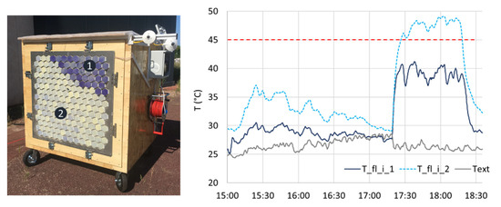
Figure 8.
Photo of the test box and temperature measurements of flaps’ inner surfaces performed on the afternoon of 9 August 2021 in Bordeaux, France. Flaps are rotated differently on areas 1 (angle = 30°) and 2 (angle = 0°) and the test-box orientation is west. The red line on the graph highlights the 45 °C temperature threshold for the flaps to change their color. Text is the external air temperature.
3.4.1. ‘Opaque’ Configuration
Measurements were performed using different test box and flap configurations. The test box was successively oriented east, south, and west. Different positions and angles for the flaps were tested:
- Position as a solar cap, i.e., the rotation axis is horizontal and on top of the base. Vertical position, i.e., the rotation axis is vertical. This configuration results in larger shadows at the beginning and end of the day when the test box is oriented south, whereas the solar cap position will have larger shadows during mid-day;
- Angle of rotation of claps of 0°, 45°, and 90°.
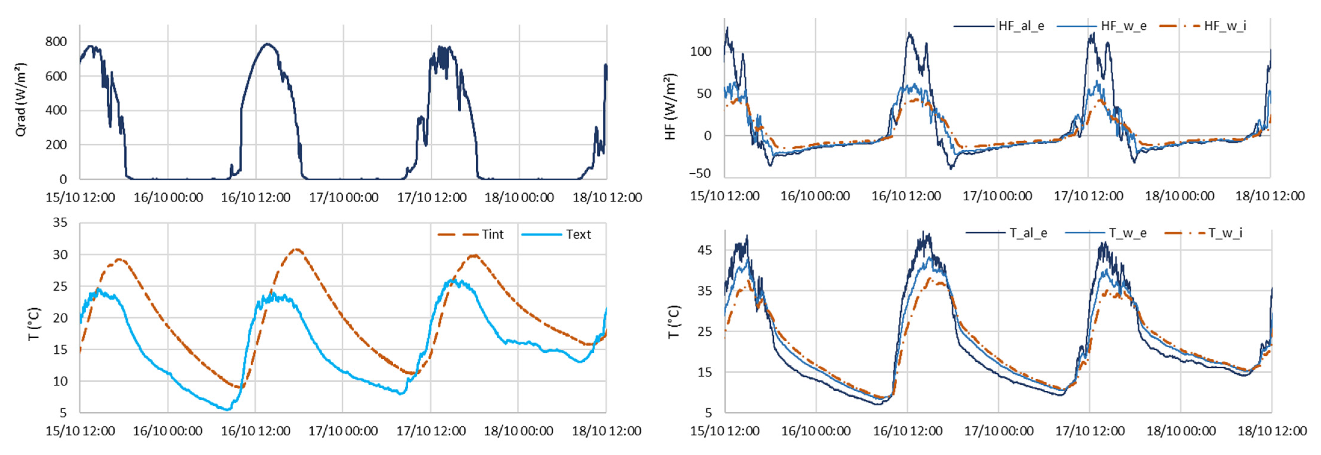
Data measured during several days with closed flaps and test box oriented south are given in Figure 9. The total inertia of the test box can be observed by identifying the phase shift between the inside and outside ambiant temperatures. The heatflows measured in different layers of the tested wall (Stegos + wall) decrease from the external layer to the internal layer. This difference is particulary high between the external surfaces of the aluminum and the plywood (HF_al_e and HF_w_e, respectively). It can be explained by the fact that the heat collected by the flaps is transferred to the 1 mm aluminum sheet and then conducted to its perimeter, owing to its high conductivity. The heat is then dissipated by convection. Accordingly, we will improve the experimental design by adding an insulation frame to the aluminum sheets.
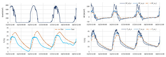
Figure 9.
(Top left) Incident solar radiation, (bottom left) internal and external air temperatures, (top right) heat flows, and (bottom right) associated temperatures in the tested façade from November 15 to November 18, 2021. Test box oriented south, angle of flaps = 0°.
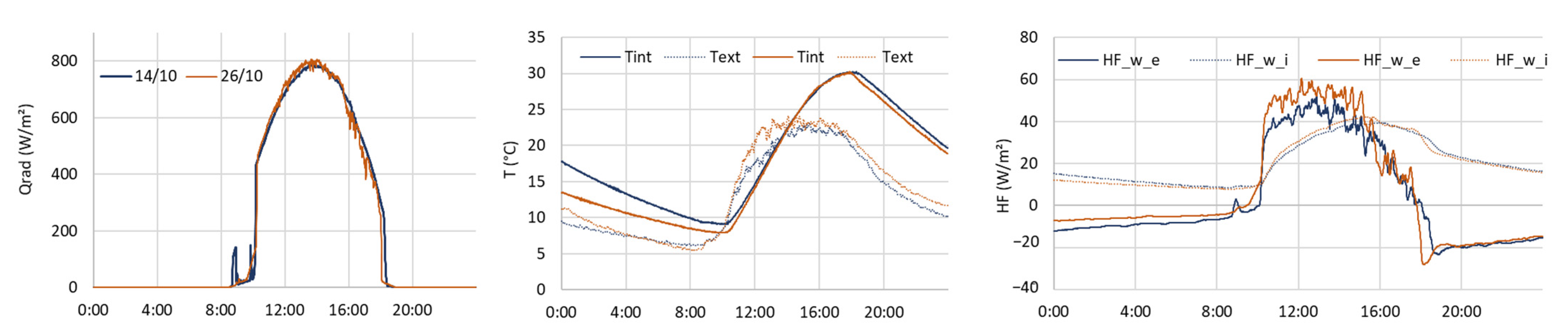
A direct comparison between the two configurations is shown in Figure 10. For similar days (maximum solar radiation and outside temperture around 800 W/m2 and 23 °C, respectively), a difference of about 13% can be observed on heat flows measured at the inner surface of the Stegos aluminum during sunlight hours. This could mean that the solar cap configuration—horizontal axis of rotation and 90° angle of flaps—transfers more heat into the test box at this time of the year; however, it is not consistent with the measured internal air temperatures, which appear to be very similar. As the measurements are shown, it is not possible to determine whether the Stegos has an insignificant impact on the test box conditions or whether the external conditions from the previous day are still having an impact.
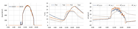
Figure 10.
Layering of measurements performed on the test box during two separate days. Incident solar radiation, air temperatures, and heat flows. Measurements on 14 October 2021: closed flaps. Measurements on 26 October 2021: opened flap with a 90° angle, along a horizontal rotation axis (solar cap configuration).
3.4.2. ‘Glazing’ Configuration
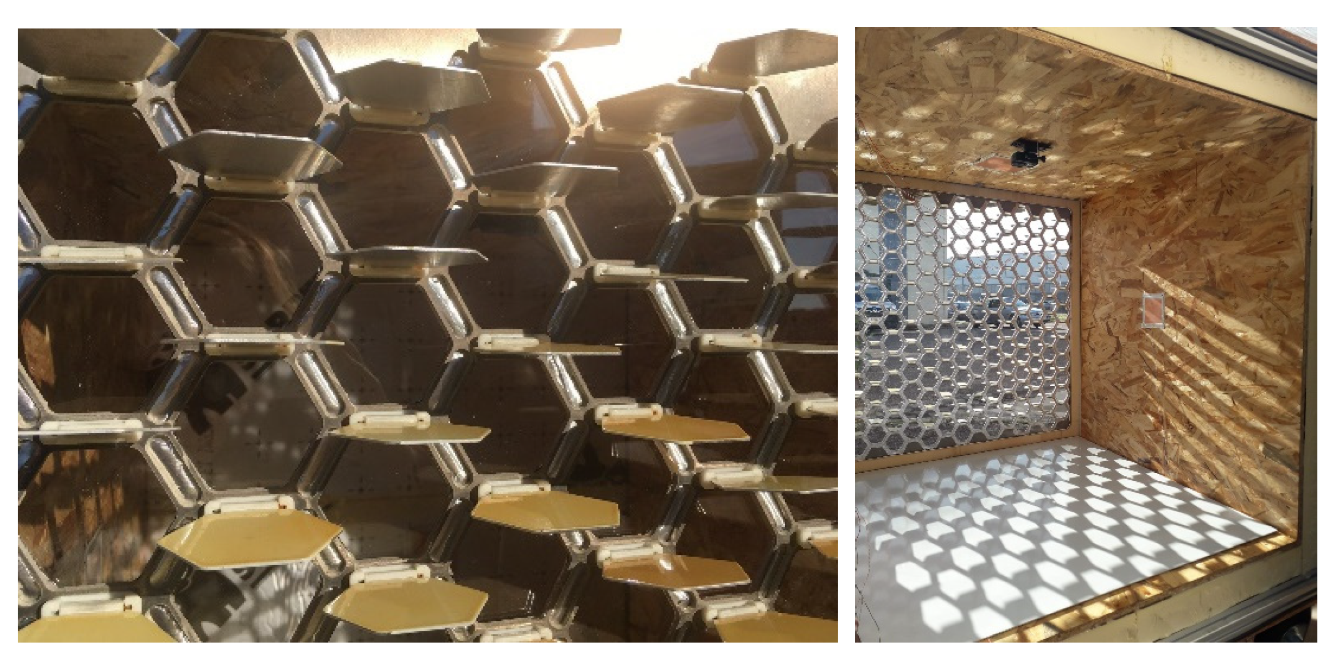
Photos of the experimentation set for the Stegos ‘glazing’ are shown in Figure 11. Pictures of the projected light and shadow on the bottom surface every 10 min of the day were taken using the camera fixed on top of the test box. The configuration sets for the test box were identical to the ones used for the experimental protocol of the ‘opaque’ configuration.
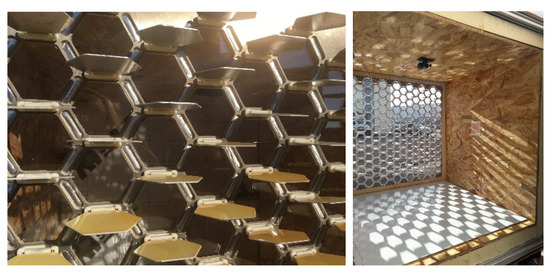
Figure 11.
Photos of the Stegos ‘glazing’ configuration on the test box with claps positioned as solar caps and opened to a 90° angle. Camera fixed on the roof wall of the test box.
The difference illustrated in Figure 12 between flap angles of 45° and 90° is visible and expected with the sun elevation in November in France.
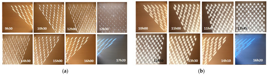
Figure 12.
Light and shadow projection on the floor of the test box at different hours of the day for two opening angles of flaps: (a) angle at 45° on November 12, and (b) angle at 90° on November 16. Blue light at the end of the day is due to more diffuse illumination than the rest of the day.
3.5. Discussion
The measurements performed on the ‘opaque’ configuration do not provide direct conclusions on the Stegos performance and its impact on a controlled volume as the test box. While useful for the characterization using geometrical and thermal models, difficulties in comparing different sets between each other are arguments to perform, in the near future, with new experimentations with the following modifications:
- Addition of insulation on the tested façade for more impact on the whole test box behavior;
- Coating of the aluminum plate with a black matte paint to reduce reflection induced by the high reflectivity of aluminum and thus increase incoming heat flows. This should help to compare different sets;
- Switch flaps coated with the blue, thermochromic paint for white- and black-painted flaps to compare the results with extreme colors and determine the contribution of the adaptive paint on the Stegos performance.
4. Towards Characterization through the Calibration of Grey Box Models
To face practical production challenges and collect feedback on bioinspired practice, the authors experimented with design processes through the prototyping of the Stegos system and the creation and use of a test bench. Several measurement campaigns (described in Part 3) provided a first assessment of the system and guidelines for improved measurements. However, intricate physical phenomena, including radiative, convective, and conductive transfers, are still to be described to define better alternatives of the concept in regards to the pursued functionalities. For this, a coupling between parametric geometric models and heat transfer models is proposed and described in the following sections.
4.1. Geometric Parametric Design
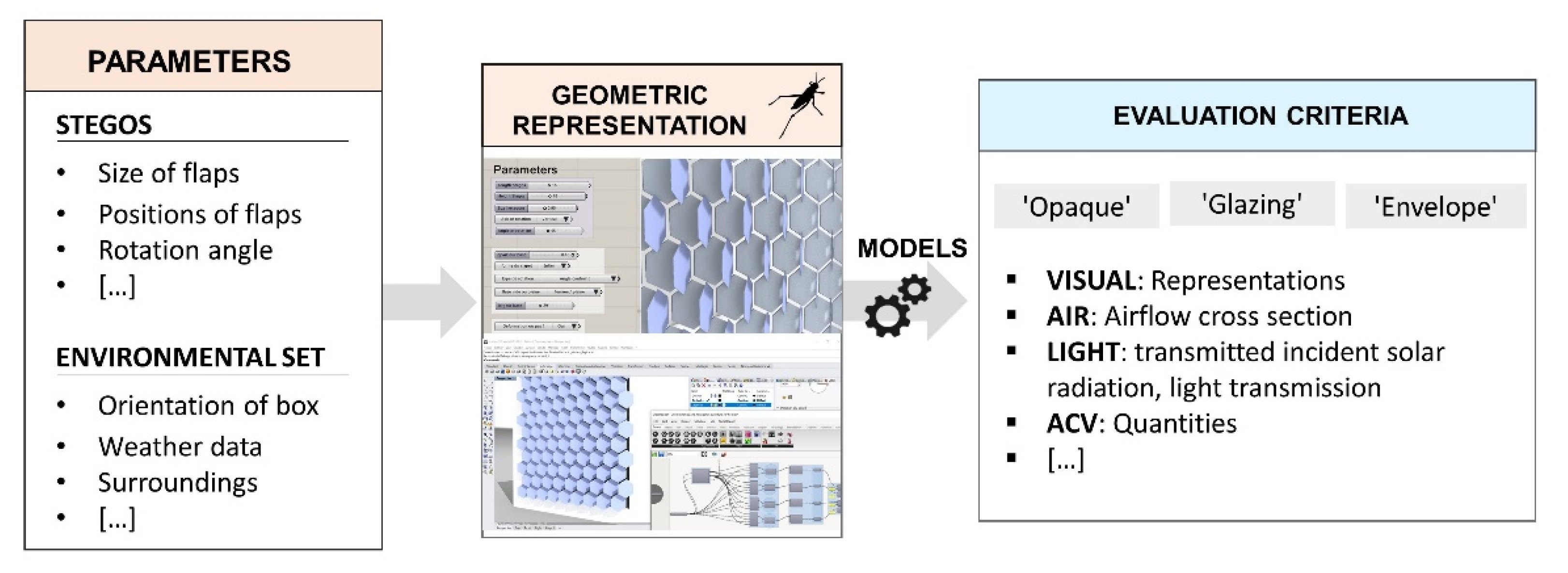
A geometrical model of the prototype integrated into the test box was created under Rhinoceros Grasshopper. Geometrical parameters, either related to the Stegos or to the general set (orientation, weather, and date), were defined as variables to be tested and compared with regard to various indicators related to air, light, and heat regulation functionalities, as displayed in Figure 13.
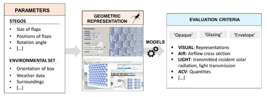
Figure 13.
Steps followed during the geometric modeling of the Stegos design implemented in the test box: (from left to right) definitions of parameters, implementation in Rhinoceros Grasshopper, use of embedded models, and evaluation according to various criteria.
In the ‘glazing’ configuration, the Stegos acts as a solar shading device and thus as a light-management system. The objective here is to validate the geometrical representation through Rhinoceros Grasshopper. For this purpose, a daylight analysis was performed on a southern-fixed orientation, located in Bordeaux (France), and with dates set as the dates of the experiments described in Part 3. The angles of the flaps varied from 0 to 90° and were positioned horizontally. A comparison between the simulation on Grasshopper and photographs of the experiments illustrated in Figure 14 shows very similar light projections. It is important to note that this comparison can only be qualified as qualitative, as the authors do not provide numerical analysis of the photographs and because of inevitable distortions due to perspective.

Figure 14.
Comparisons between simulations on Rhinoceros Grasshopper and photographs of Stegos in solar cap configuration. (a) Comparison of the vertical shadow for an angle of 90°. Date: 27 October 12:00. (b) Comparison of the horizontal shadow on the floor of the test box for an angle of 90°. Date: 19 November 15:00.
The results of these simulations alone are not sufficient to provide satisfactory design configuration in regards to light regulation in the ‘glazing’ scenario. To be validated, they would require the use of other criteria—for instance, daylight or glare analysis showing adequate lighting in the enclosure during winter. In this sense, multi-objective optimization would be adequate.
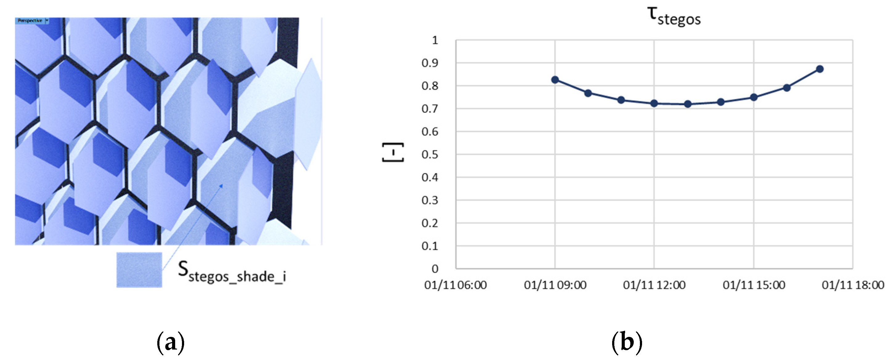
Nevertheless, a comparison of the simulations with measured projections validates the geometrical modeling, and it can provide valuable inputs to better detail the external boundary conditions in a heat-transfer model. We define two parameters, the horizontally projected shadow gfloor,Stegos and the vertically projected shadow τStegos on the tested façade. Those can be simulated and be inputs of the ‘glazing’ and ‘opaque’ façade thermal model, respectively:
with Sfloor,shade indicating the shaded surface on the test box floor, Sfloor,tot indicating the total surface area of the test box floor, SStegos,shade indicating the shaded surface on the Stegos, and SStegos,tot indicating the total surface area of the tested façade (Figure 15).
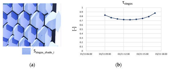
Figure 15.
(a) The shaded surface on the Stegos is the sum of all SStegos_shade_i. (b) Simulated τStegos for the 1 November (data for location: Bordeaux, France).
The Rhinoceros Grasshopper model was used to calculate one value of the τStegos, needing 30 s computational time on a regular office computer.
4.2. Heat-Transfer Models: Grey-Box Approach Proposal
The complexity of the physical phenomena taking place in the Stegos integrated into the test box prevents proposing a fully descriptive model. An alternative is to use partial theoretical models coupled with data from performed measurements (Part 2), known as the grey-box approach.
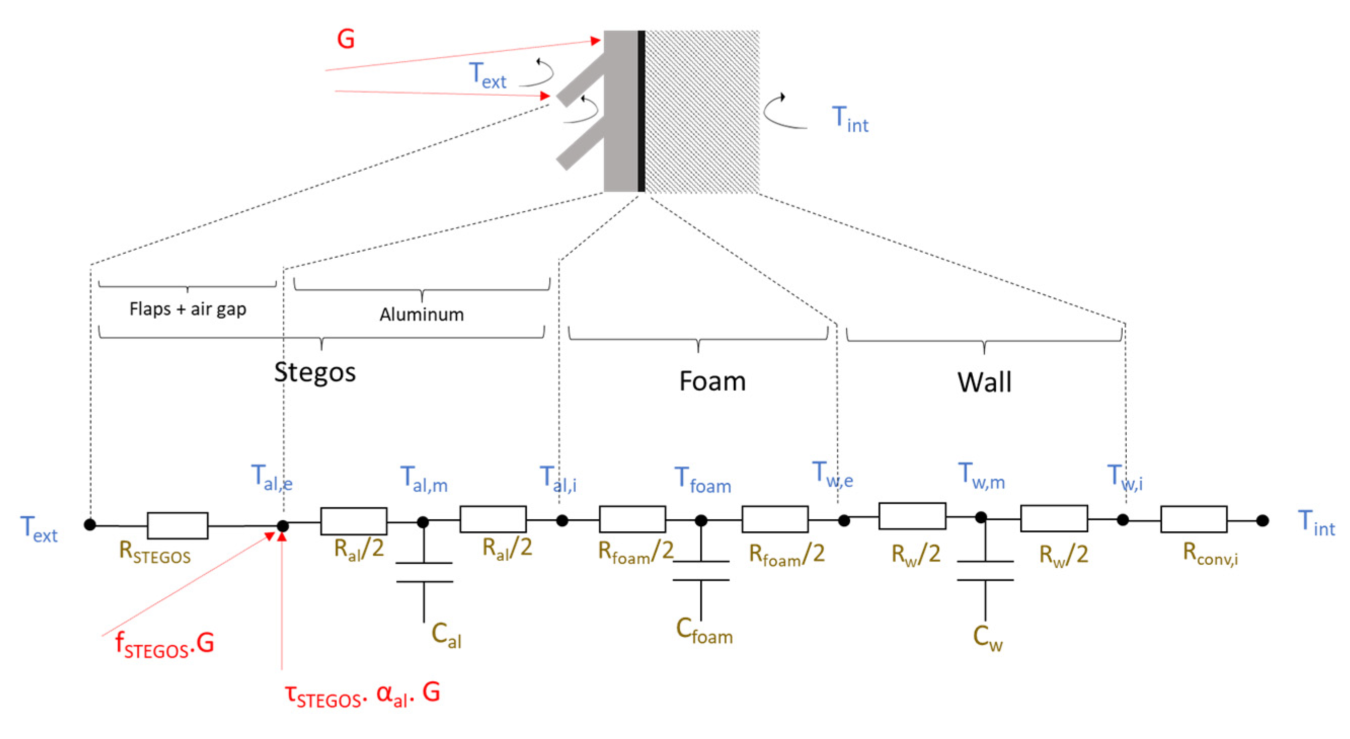
An RC (resistance, capacitance) model is proposed and represented in Figure 16. The following hypotheses and simplifications are considered:
- The tested façade, including Stegos, is considered as a semi-infinite environment, meaning that it is extending to infinity in all three directions, but only on one side of a plane, here, the external environment.
- Only one layer of aluminum is included in the model; the 4 mm support frame is perforated with hexagonal holes and can thus be neglected.
- The heat transfers are considered in one dimension, with internal boundary conditions based on the internal air temperature and a fixed convective coefficient. Additionally, the external boundary condition is given by the weather measurement.
- The proposed model includes conductive, convective, and longwave radiative heat transfers between the outside surface of Stegos (the aluminum plate) and the external environment in a single thermal resistance.
- The incident solar radiation is taken into account in two ways. The first contribution is expressed as direct and diffuse radiation on the external surface of the aluminum plate using the projected shadow ratio calculated with geometrical models (see Part 3.1). A second contribution is provided through a factor fStegos, which represents a solar intake in the Stegos through the flaps.
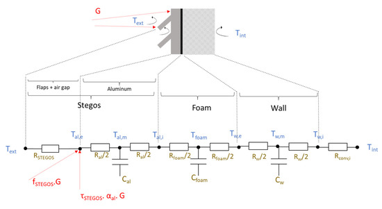
Figure 16.
RC model of the wall assembly (case of ‘opaque wall’ configuration) with Ci thermal capacities and Ri thermal resistances of the nodes.
Figure 16.
RC model of the wall assembly (case of ‘opaque wall’ configuration) with Ci thermal capacities and Ri thermal resistances of the nodes.
5. Conclusions and Prospects
In this paper, we presented an envelope design derived from a bioinspired framework. The system is a deformable and deployable skin, which can be positioned in front of an opaque wall, as a glazing, or as the envelope itself. According to the configuration, it can manage multiple regulation factors, such as heat, light, and air. Moreover, the deployable elements are coated with an adaptive paint, in which the absorption coefficient changes with the surface temperature.
A non-deformable but deployable version was prototyped and integrated into an orienTable 1 m3 insulated box as a test bench. Measurements of heat and light transfers were performed for the opaque and glazing configurations. Limitations were identified in the experimental protocols owing to the high reflectivity of the internal aluminum layer limiting the solar gains, and as such, mitigating the impact of Stegos as a solar-shading device. This layer will be painted in black, resulting in higher heat transfers and allowing better identification of the impact of each parameter.
The proposed bioinspired design methodology was experimented with at the beginning of the project and resulted in the Stegos design. Feedback from this experience allows it to further improve its implementation, especially with the additional data.
Future work includes the implementation of the ‘envelope’ configuration in the test bench to perform measurements of thermal, light, and air transfers. A deformable version of the concept is also planned to be prototyped and tested as well.
A follow-up of this project will be a generic methodology for the characterization of dynamic envelope elements, such as a Stegos prototype based on the calibration of a model against measurements on similar protocols. The introduced parameters RStegos and fstegos of the proposed RC model characterize the impact of Stegos on the opaque wall, but they are not fully descriptive. We will use optimization methods to identify those parameters in this generic grey-box model and stochastic methods using pseudo aleatory exploration processes. Once calibrated, the model can be applied to design new, more efficient versions of Stegos, and it will offer the opportunity to numerically integrate such an innovative envelope element in thermal buildings’ simulation platforms to evaluate its global impact on different buildings.
Author Contributions
Conceptualization, T.H., A.D., T.V.W., F.A. and D.B.; methodology, T.H., A.D., T.V.W., F.A. and D.B.; validation, D.B. and F.A.; data curation, T.H.; energy models, T.H. and A.D.; writing—original draft preparation, T.H.; writing—review and editing, T.H., A.D., T.V.W., F.A. and D.B. All authors have read and agreed to the published version of the manuscript.
Funding
This research was carried in the frame of the BIOINSPIRED project, funded by the Regional Committee of Nouvelle Aquitaine (CNRA) and the Investments for the Future Program (PIA).
Data Availability Statement
Publicly available datasets were analyzed in this study. The data can be found at https://doi.org/10.5281/zenodo.5762420 (accessed on 21 January 2022).
Acknowledgments
Additional help came from Damien Decker for the prototyping and measurements, Saeed Kamali for the illustrations, and Myriame Ali-Oualla and Kaïs Bhouri for contributing to the Stegos concept. The authors thank them.
Conflicts of Interest
The authors declare no conflict of interest.
Nomenclature
| T | Temperature (°C) or (K) |
| HF | Heat flux (W/m2) |
| S | Surface (m2) |
| A | Absorption coefficient (-) |
| R | Reflectance (-) |
| τ | Solar transmission coefficient (-) |
| λ | Thermal conductivity (W/m·K) |
| R | Thermal resistance (K/W) |
| h | Transmitted heat coefficient (W/K) |
| C | Heat capacity (J/K) |
| G | Normal direct and diffuse solar radiation (W/m²) |
| Abbreviations | |
| ABS | Acrylonitrile butadiene styrene |
| OSB | Oriented strand board |
References
- Grosso, A.E.D.; Basso, P. Adaptive Building Skin Structures. Smart Mater. Struct. 2010, 19, 124011. [Google Scholar] [CrossRef]
- Aelenei, D.; Aelenei, L.; Vieira, C.P. Adaptive Façade: Concept, Applications, Research Questions. Energy Procedia 2016, 91, 269–275. [Google Scholar] [CrossRef] [Green Version]
- FACADE 2018—Adaptive! Final Conference—COST Action TU1403—Adaptive Facades Network. Available online: http://tu1403.eu/?page_id=1291 (accessed on 26 November 2021).
- Final Booklet Series COST TU1403—COST Action TU1403—Adaptive Facades Network. Available online: https://tu1403.eu/?page_id=1562 (accessed on 21 January 2021).
- Benyus, J.M. Biomimicry: Innovation Inspired by Nature; Nachdr.; Perennial: New York, NY, USA, 2009; ISBN 978-0-06-053322-9. [Google Scholar]
- Mazzoleni, I.; Maya, A.; Bang, A.; Molina, R.; Barron, F.; Pei Li, Y. Biomimetic Envelopes: Investigating Nature to Design Buildings. In Proceedings of the First Annual Biomimicry in Higher Education Webinar; The Biomimicry Institute: Missoula, MT, USA, 2011; pp. 27–32. [Google Scholar]
- Knippers, J.; Nickel, K.G.; Speck, T. (Eds.) Biomimetic Research for Architecture and Building Construction; Biologically-Inspired Systems; Springer International Publishing: Cham, Switzerland, 2016; Volume 8, ISBN 978-3-319-46372-8. [Google Scholar]
- López, M.; Rubio, R.; Martín, S.; Croxford, B. How Plants Inspire Façades. from Plants to Architecture: Biomimetic Principles for the Development of Adaptive Architectural Envelopes. Renew. Sustain. Energy Rev. 2017, 67, 692–703. [Google Scholar] [CrossRef]
- Cruz, E.; Hubert, T.; Chancoco, G.; Naim, O.; Chayaamor-Heil, N.; Cornette, R.; Menezo, C.; Badarnah, L.; Raskin, K.; Aujard, F. Design Processes and Multi-Regulation of Biomimetic Building Skins: A Comparative Analysis. Energy Build. 2021, 246, 111034. [Google Scholar] [CrossRef]
- Wanieck, K.; Fayemi, P.-E.; Maranzana, N.; Zollfrank, C.; Jacobs, S. Biomimetics and Its Tools. Bioinspired Biomim. Nanobiomater. 2017, 6, 53–66. [Google Scholar] [CrossRef] [Green Version]
- Chakrabarti, A.; Blessing, L. A Review of Theories and Models of Design. J. Indian Inst. Sci. 2015, 95, 16. [Google Scholar]
- Hatchuel, A.; Weil, B. C-K Design Theory: An Advanced Formulation. Res. Eng. Des. 2009, 19, 181–192. [Google Scholar] [CrossRef]
- Fayemi, P.-E. Innovation Par La Conception Bio-Inspiree: Proposition D’un Modele Structurant Les Methodes Biomimetiques Et Formalisation D’un Outil De Transfert De Connaissances. Ph.D. Thesis, Ecole nationale supérieure d’arts et métiers—ENSAM, Paris, France, 2016. [Google Scholar]
- Salgueiredo, C.F.; Hatchuel, A. Modeling Biologically Inspired Design with The C-K Design Theory. In Proceedings of the International Design Conference—DESIGN 2014, Dubrovnik, Croatia, 19–24 May 2014. [Google Scholar]
- Jacobs, S.R.; Nichol, E.C.; Helms, M.E. “Where Are We Now and Where Are We Going?” The BioM Innovation Database. J. Mech. Des. 2014, 136, 111101. [Google Scholar] [CrossRef]
- Chirazi, J.; Wanieck, K.; Fayemi, P.-E.; Zollfrank, C.; Jacobs, S. What Do We Learn from Good Practices of Biologically Inspired Design in Innovation? Appl. Sci. 2019, 9, 650. [Google Scholar] [CrossRef] [Green Version]
- Graeff, E.; Maranzana, N.; Aoussat, A. Biomimetics, Where Are the Biologists? J. Eng. Des. 2019, 30, 289–310. [Google Scholar] [CrossRef]
- Hubert, T.; Wu, T.V.; Dugué, A.; Bruneau, D.; Aujard, F. A Framework for the Design of Bioinspired Building Envelopes: Case Study of An Adaptive Skin Inspired by the Morpho Butterfly. In Proceedings of the Advanced Building Skin Conference, Bern, Switzerland, 21–22 October 2021; p. 9. [Google Scholar]
- ISO 18458:2015; Biomimetics—Terminology, Concepts and Methodology. Beuth Verlag: Berlin, Germany, 2015; p. 27.
- Farzaneh, H.; Helms, M.; Muenzberg, C.; Lindemann, U. Technology-Pull And Biology-Push Approaches in Bio-Inspired Design—Comparing Results from Empirical Studies On Student Teams. In Proceedings of the International Design Conference—DESIGN 2016, Dubrovnik, Croatia, 16–19 May 2016. [Google Scholar]
- Hansell, M.H. Built by Animals: The Natural History of Animal Architecture; 1. publ. in paperback.; Oxford University Press: Oxford, UK, 2009; ISBN 978-0-19-920557-8. [Google Scholar]
- Badarnah, L. Form Follows Environment: Biomimetic Approaches to Building Envelope Design for Environmental Adaptation. Buildings 2017, 7, 40. [Google Scholar] [CrossRef] [Green Version]
- Cruz, E. Multi-Criteria Characterization of Biological Interfaces: Towards the Development of Biomimetic Building Envelopes. Ph.D. Thesis, MNHN, Paris, France, 2021. [Google Scholar]
- Research unit CNRS-MNHN 7179 MECADEV—Adaptive Mechanisms & Evolution. Available online: https://mecadev.cnrs.fr/index.php?navlang=en (accessed on 26 November 2021).
- Chapman, R.F.; Simpson, S.J.; Douglas, A.E. The Insects: Structure and Function, 5th ed.; Cambridge University Press: New York, NY, USA, 2013; ISBN 978-0-521-11389-2. [Google Scholar]
- Van Hooijdonk, E.; Berthier, S.; Vigneron, J.-P. Contribution of Both the Upperside and the Underside of the Wing on the Iridescence in the Male Butterfly Troïdes Magellanus (Papilionidae). J. Appl. Phys. 2012, 112, 74702. [Google Scholar] [CrossRef]
- Berthier, S. Thermoregulation and Spectral Selectivity of the Tropical Butterfly Prepona Meander: A Remarkable Example of Temperature Auto-Regulation. Appl. Phys. A 2005, 80, 1397–1400. [Google Scholar] [CrossRef]
- Bhatia, S.C. Solar Radiations. In Advanced Renewable Energy Systems; Elsevier: Amsterdam, The Netherlands, 2014; pp. 32–67. ISBN 978-1-78242-269-3. [Google Scholar]


Publisher’s Note: MDPI stays neutral with regard to jurisdictional claims in published maps and institutional affiliations. |
© 2022 by the authors. Licensee MDPI, Basel, Switzerland. This article is an open access article distributed under the terms and conditions of the Creative Commons Attribution (CC BY) license (https://creativecommons.org/licenses/by/4.0/).