Abstract
In this work is considered the connection of a photovoltaics (PV) solar plant to the main grid through a Direct Current (DC) MicroGrid and a hybrid storage system, composed of a battery and a supercapacitor, in order to satisfy constraints of grid connection (the so-called Grid-Codes). The objective, and main contribution of this paper, is to stabilize the DC MicroGrid voltage in spite of large variations in production and consumption, using a nonlinear hierarchical easy-to-implement control strategy. Here is presented the MicroGrid’s control design based on detailed models of the photovoltaic energy sources and the storage systems. Such DC grids may present an unstable behavior caused by the PV’s intermittent output power, by switching ripples from the power converters and their power electronics, and oscillatory currents produced by some types of loads. Therefore, the system is subject to both fast and slow variations, and its stabilization is based on different technologies of storage, such as battery and supercapacitor, and control algorithms designed thanks to the use of time-scale separation between different components of the storage systems. The obtained nonlinear results are stronger than current linear controllers, allowing to keep operating margins around the voltage reference. At the same time, in this work, insights from power systems practice have been used, aiming to obtain a very simple and easy-to-implement control scheme. Detailed simulation results are provided to illustrate the behavior and effectiveness of the proposed stabilization technique.
The integration of renewable energy sources (renewables) and modern loads on a large scale is a challenging task due to their intermittent nature. As a consequence, the power grid becomes vulnerable and subject to instability issues. In particular, the presence of Distributed Generation (DG) such as solar energy, or modern loads as electric vehicles and intelligent buildings in a distribution network creates challenges that can be addressed by the concept of MicroGrids [1,2]. In MicroGrids, storage devices are used to compensate for intermittent behavior and then secure grid integrity concerning the increase in the number of DG elements [3]. They allow for the possibility to design control systems to ensure stability during the injection and consumption of intermittent power.
The present paper focuses on stabilizing voltage on a Direct Current (DC) MicroGrid, used to integrate renewable power. This stabilization is obtained by designing a hierarchical control strategy that considers the power balance between the energy sources and loads. The nonlinear control scheme has been developed for a DC MicroGrid composed of photovoltaic (PV) panels, two storage devices (a battery and a supercapacitor) acting at different time scales, a DC load and its connection to an Alternate Current (AC) grid.
In the field of MicroGrids, linear control methods are generally used, as in [4,5,6,7,8]. These works use the small signal model of converters and apply the industrial standard PI control, mostly addressing the stabilization of the MicroGrid’s DC voltage. In those works, the control voltage performances are acceptable in terms of voltage overshoot and settling time, and stabilization of the whole DC MicroGrid is attained. Nevertheless, such control methods can correctly stabilize a MicroGrid only in steady state, when parameters do not vary much. On the other hand, if several parameters are time-varying, such linear controllers cannot ensure good performance (sometimes not even stability) for the several operating points associated with such variations. Therefore, developing new control structures to improve systems’ performance is necessary.
On the other hand, Refs. [9,10,11] propose new control strategies based on nonlinear control theory, using state average model of converters. On those, the control strategy is designed globally with a high-level controller, and act locally on converters with local control algorithm. With this control strategy the system should be able to balance supply power and demand load in order to obtain a good performance in transient conditions and steady-state. Nevertheless, such results are rather complex, with algorithms that are difficult to implement in small and low-cost micro-controllers, distributed on a large number of components. The now proposed control philosophy is also based on a Systems of Systems approach, where each brick is designed to participate in ensuring the stability of the whole DC voltage system. This control strategy was developed in [12,13,14,15,16,17], addressing different applications. In the present paper, such techniques were used to design a control strategy to stabilize the DC MicroGrid voltage through a control algorithm that defines priorities in relation to the photovoltaic system, load, and constraints for storage system operation.
Other articles (see [18,19,20,21]) have also proposed a hierarchical control scheme focusing on a centralized supervisory control level and a distributed lower-level control, based on nonlinear theory. These controllers present rigorous analysis of the interaction between the different dynamics, and aim to stabilize the whole system, even when large variations of power production and consumption occur, and to ensure power quality while providing power to the main AC grid. Differently to those results, the present paper has used assumptions coming from the physics of power systems to reduce the complexity of the control design procedure. However, these assumptions make stability analysis to hold inside a smaller operation region than more complex results. Nevertheless, these insights from power systems’ practice allow simpler algorithms, well suited for a distributed implementation in low-cost micro-controllers in a low voltage grid, and still allow to stand large disturbances inside a well-defined operation region.
In this scheme, the higher-level controller provides reference values for the local controllers. Thereafter, we develop these distributed controllers using backstepping, feedback linearization, and Lyapunov-based control techniques. Power system stability is analyzed by intermediate Lyapunov functions provided for each step to construct a composite Lyapunov function for the overall stability analysis. The local controllers are implemented at the actuators’ level on each device’s power converters (PV panel, battery, supercapacitor). The reference is obtained by a Maximum Power Point Tracking (MPPT) algorithm concerning the PV power source. The supervisory higher-level controller is allowed to reduce the power reference in case of overproduction. The higher-level controller provides power references for the storage devices to cope with power imbalance in the whole system.
This paper is organized as follows. In Section 1, the model for the DC MicroGrid is introduced; in Section 2 the DC MicroGrid Control strategy is drawn; in Section 3 low-level control laws for each subsystem are designed; in Section 4 the stability analysis for the overall interconnected system is done; Section 5 provides simulation results about the connected system behavior; finally, Section 6 presents the conclusions.
1. DC MicroGrid Model
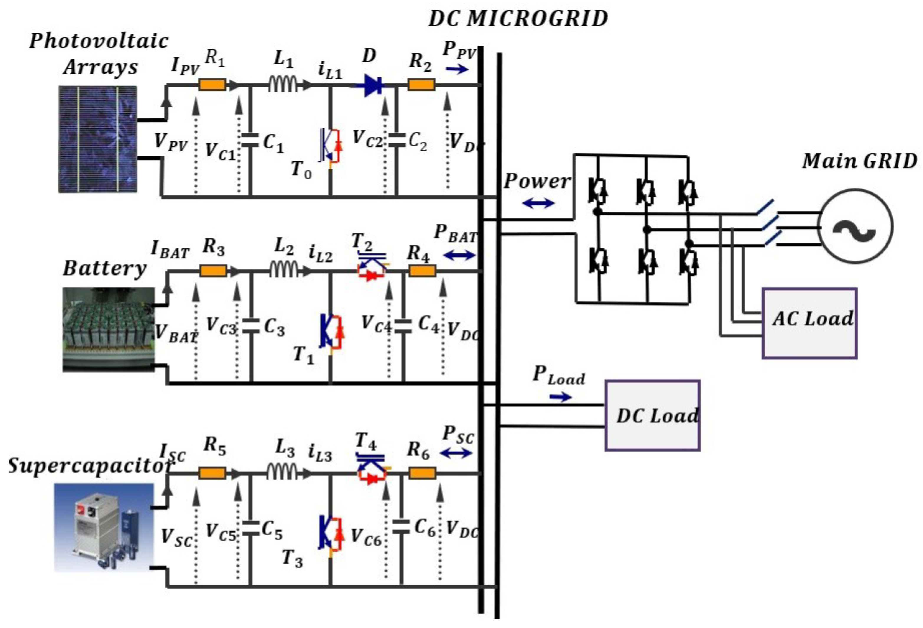
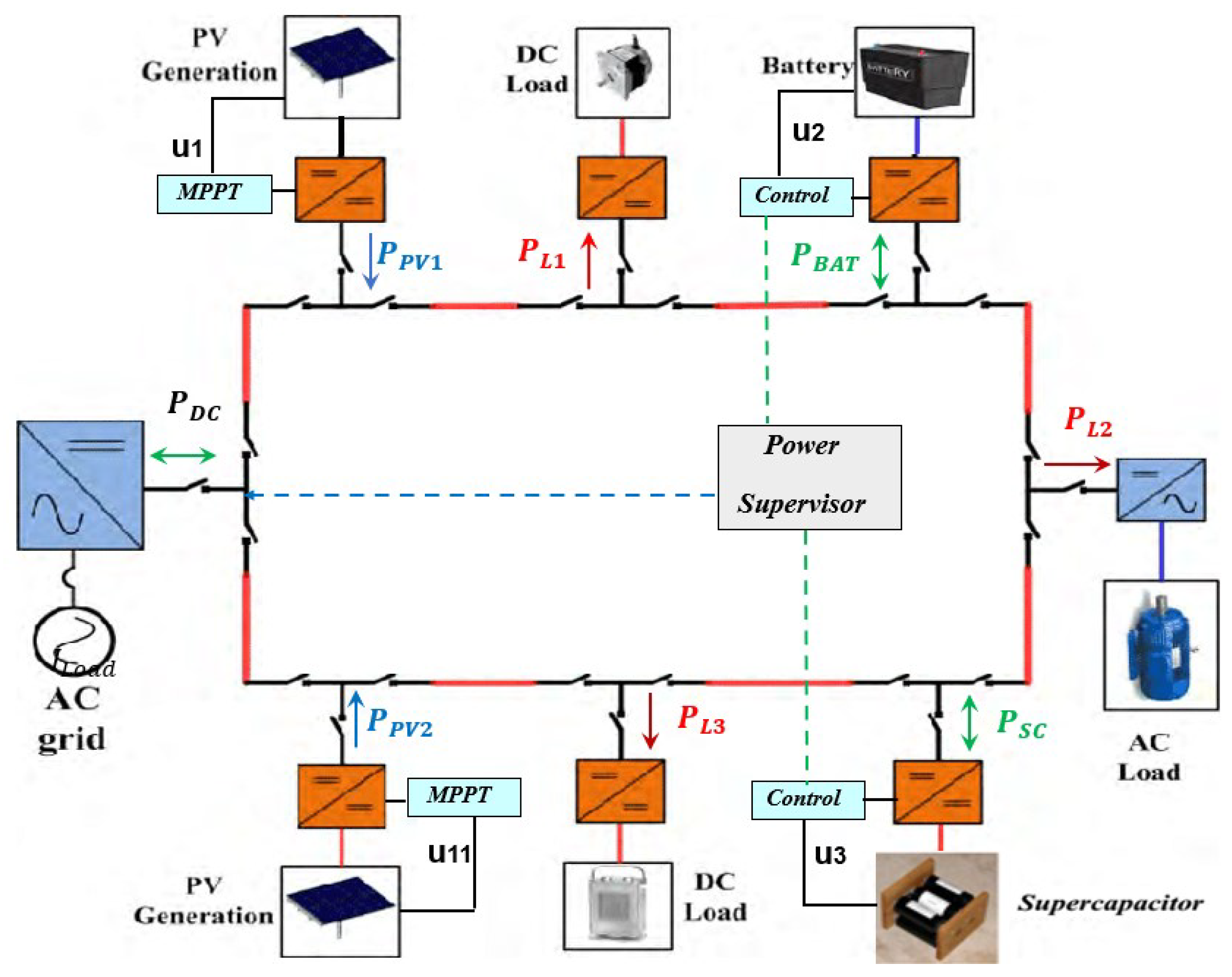
A general DC MicroGrid as in Figure 1 is composed of Distributed Generation (DG) such as photovoltaic arrays, energy storage elements such as supercapacitors and batteries, DC loads and grid-tied converters [22]. The energy storage elements play an important role for the entire power management of the DC MicroGrid as mentioned. They ensure a secured network, provide high quality power and maintain the common DC grid voltage stable [23]. Bidirectional converters are used to charge or discharge the energy storage elements such as the battery and the supercapacitor. The load (an electric vehicle charge station for example) is modeled as a variable resistance, which in the present case is more delicate than constant power loads.
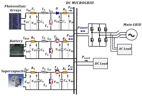
Figure 1.
The considered DC MicroGrid.
In the following, the different components of the DC MicroGrid are described.
1.1. PV System Modeling
1.1.1. Solar Array
A complete solar panel model with series and parallel connection is proposed [24,25]. The PV is represented as a current source. Due to the variations of the temperature and the solar radiance, the current and the voltage generated by the PV panel vary.
The PV DC/DC boost converter operates following references given by a standard MPPT algorithm (not discussed in this paper) under varying levels of irradiation and temperatures [24,25,26].
1.1.2. DC/DC Boost Converter
The DC/DC converter used to control the PV array is an unidirectional boost converter. It is represented by three state variables: the voltages on the capacitors and and the current in the inductance .
The mathematical model for the DC/DC boost converter that interconnects the PV to the DC grid is obtained based on power electronics averaging technique (see [27,28,29,30]), and is given by (1).
1.2. Storage System
The hybrid storage system (battery-supercapacitor) adopts the advantages of both technologies, high power density from the supercapacitor and high energy density from the battery. The proposed hybrid storage consists of a lead acid battery and a supercapacitor, as in [3,31,32,33].
1.2.1. Battery Model
The chosen model for the study is based on the resistive Thevenin model for a Lead Acid Battery, considered as a voltage generator [34].
1.2.2. Supercapacitor
The Supercapacitor is modeled by the so-called three-branch model, extracted from the transmission line modeling. It is connected to the DC grid by a DC/DC bidirectional boost converter as in [35,36].
1.2.3. Bidirectional Boost Converters
The bidirectional boost converter controlling the battery is given by (2), based on the voltages on the capacitors and and the current in the inductance (see [29,30,32,37]).
The bidirectional boost converter controlling the supercapacitor is modeled based on the voltages on the capacitors and the current in the inductance , , , shown by (3), (see [29,30,32]).
1.3. Interconnected Model
The mathematical model for the DC grid in Figure 1 is obtained based on the power electronics averaging technique [27]:
where , , , , , , , , , , , , , , and are known positive values of resistances, inductances and capacitors respectively, and represents the DC demanded power load. To model the switches, small resistances and are included to take into account conduction losses. and are the photovoltaic panel, battery, supercapacitor and DC MicroGrid voltages, respectively. The measured output vector is composed by and . The control inputs and represent the duty cycles of each converter. Equation (4) describes by Kirchhoff’s law the voltage variation due to the sum of all currents in the DC bus .
2. DC MicroGrid Control Strategy
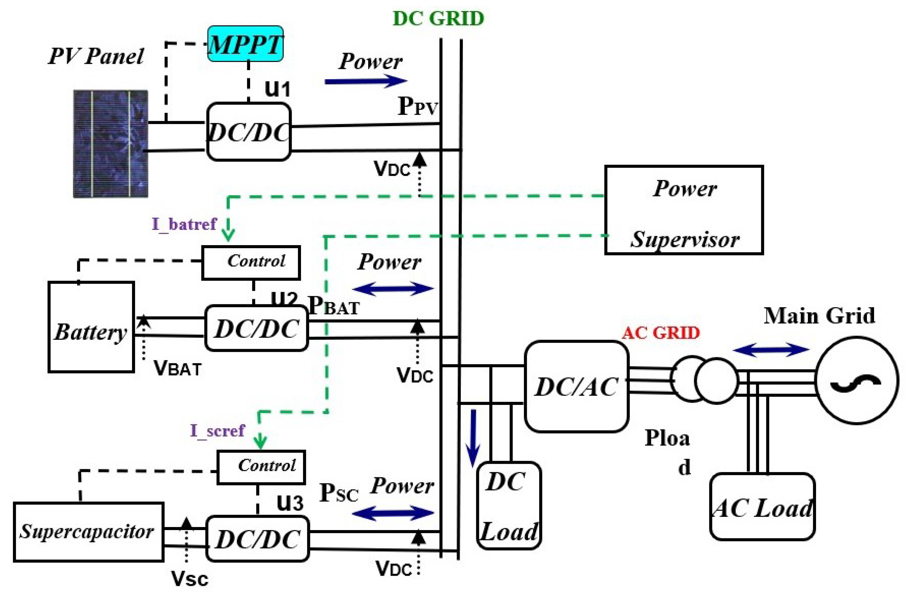
The target for the controller is to stabilize the DC bus voltage around the desired value, then ensuring power quality and allowing the DC MicroGrid to manage the desired amount of power. The proposed control will be based on two control layers (see Figure 2). First, we define the high level controller to give reference values for lower local controllers. Thereafter, we develop a local control using backstepping and Lyapunov-based techniques.
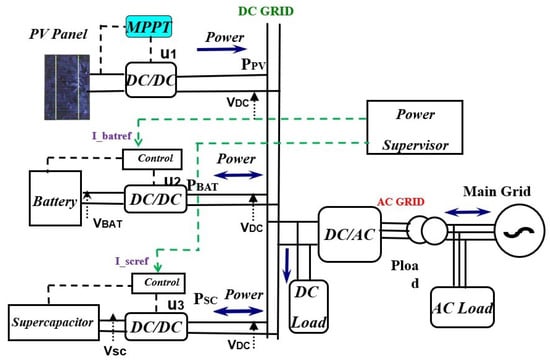
Figure 2.
DC MicroGrid Control strategy.
2.1. High Level Controller for PV Array Source
A Maximum Power Point Tracking (MPPT) algorithm is used to extract the maximum power from a photovoltaic array of solar cells. To accomplish this task, a time varying (piecewise constant) desired voltage reference is provided by the MPPT. In this paper, the Incremental Conductance method is applied (see [25,38,39]).
2.2. High Level Controller for Storage System
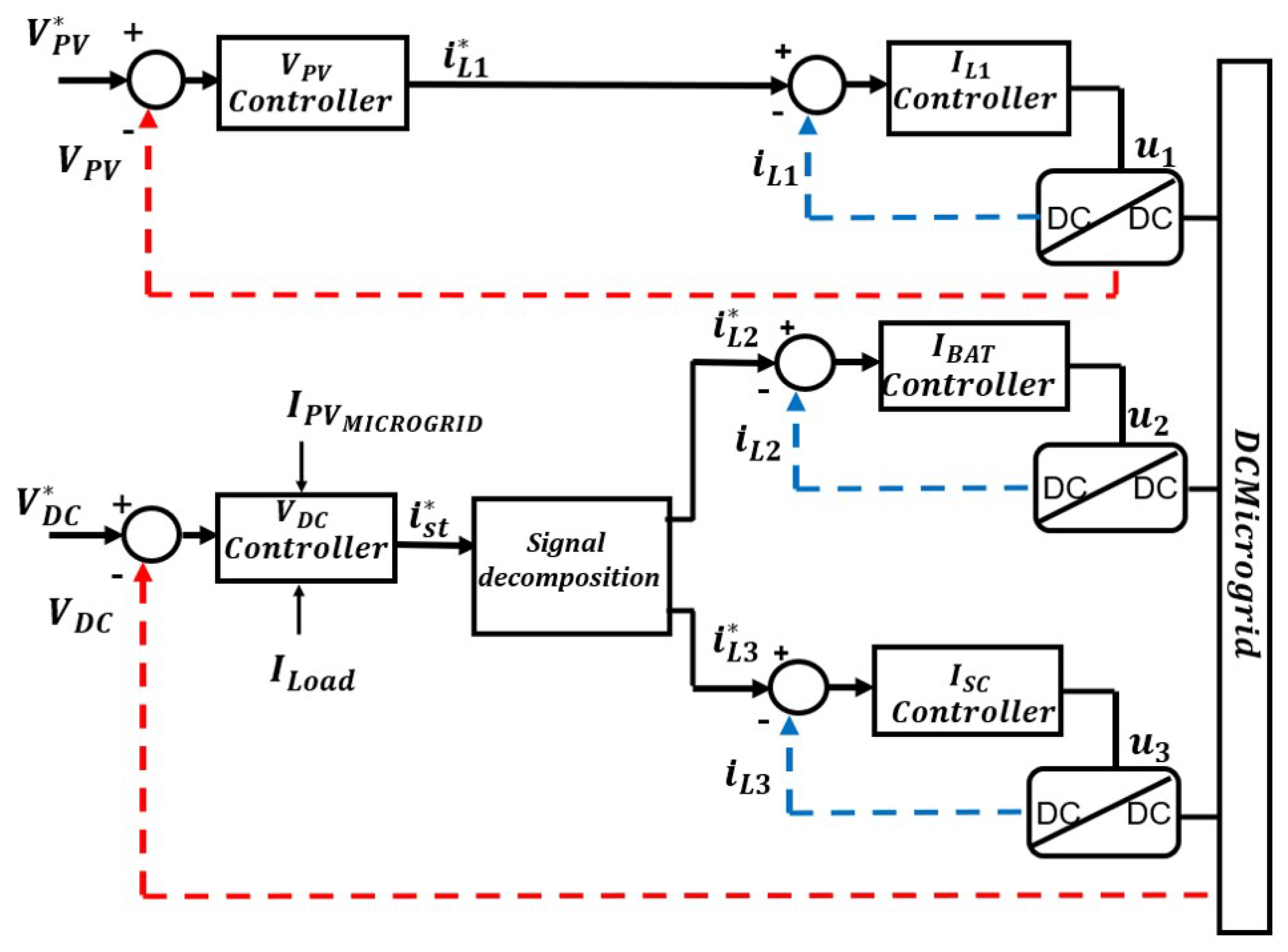
We rely on the storage system (battery + supercapacitor) to act as a buffer to absorb the current (power) variations and stabilize the DC bus. Based on the physical characteristics of the storage components, and in particular on the current limitations from the battery, we indicate: 1—to consider a current reference based on power balance equations for the whole system; 2—to use a time-scale separation to decompose it in two components, a fast one () and a slow one (), as shown in Figure 3. The slow component will be used as the reference for the battery’s power supply, while the fast component will be the reference power for the supercapacitor. This time-scale separation is obtained by the introduction of a first-order low-pass filter that decomposes the current reference in two references for the battery and supercapacitor [40]
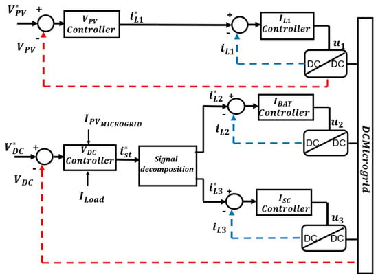
Figure 3.
The adopted time-scale-depending control strategy.
The two components are chosen to keep sufficient time-scale separation between the lower and higher-level control objectives (see [41]), and to ensure that the battery does not need to react faster than its specifications allow. Therefore, we target to extend the lifespan of the battery [10].
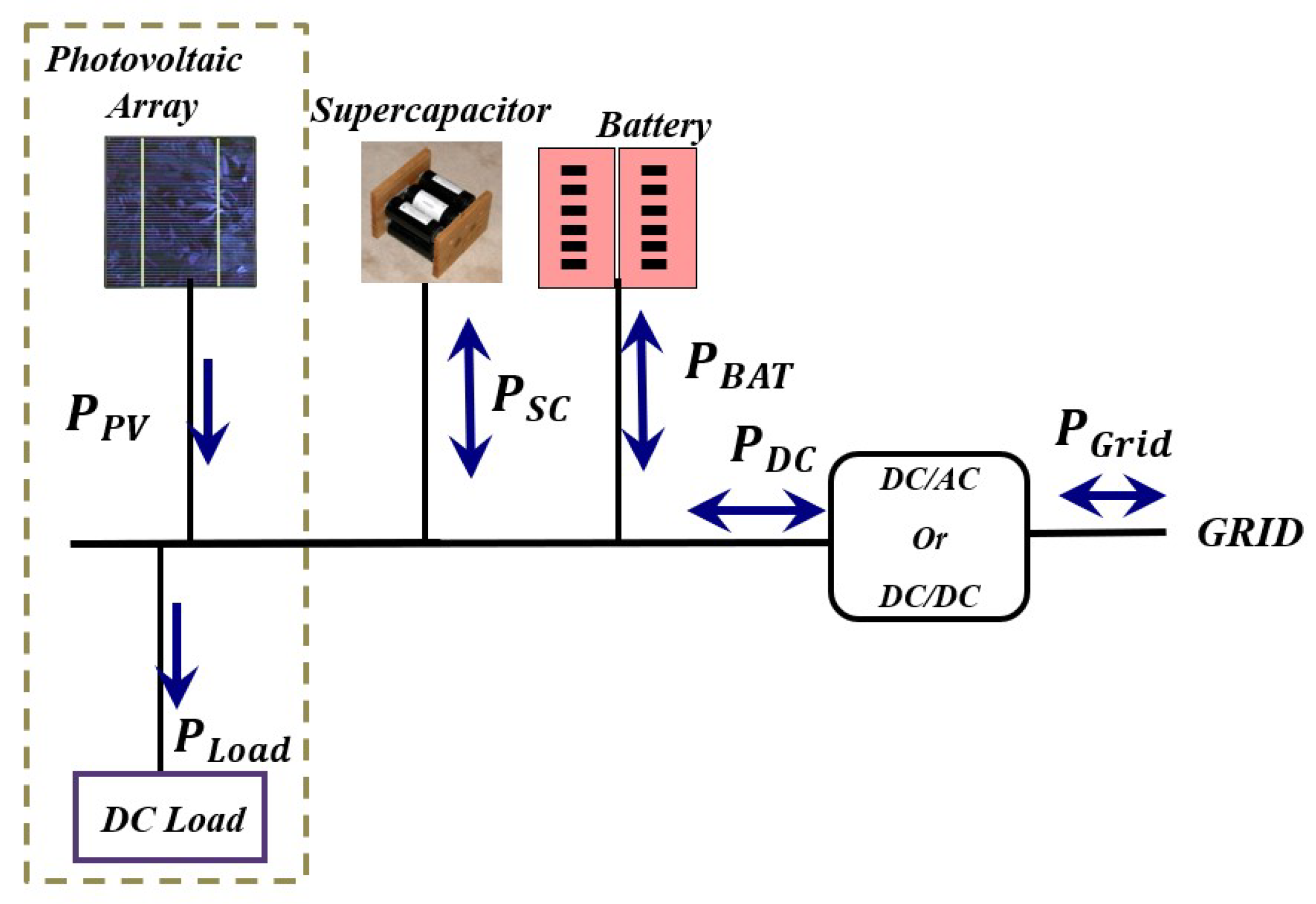
The power flow of the different elements of DC MicroGrid (see [22]) will depend on the grid topology. Most works consider a radial DC MicroGrid for its simplicity while yet capturing most challenges existing in DC MicroGrids. Radial systems are easier for installation and operation and meet the objective of designing a plug-and-play system which allows a greater penetration of renewable energy into the network. The proposed control strategy is also applicable for ring or bus [42] topologies (which are simpler than radial), and may also be implemented in meshed ones. For the latter it would be necessary to prevent congestion problems, that is not addressed in the present paper, and is usually approached with higher-level controllers, closer to optimization and communication techniques. Bus topology is currently used in residential buildings, where low-voltage DC bus is preferred to match the voltage level of many appliances and to avoid extra DC-DC conversion stages. Additionally, in such systems, loads and AC grid interface can be located close to each other in order to reduce the distribution losses [43]. A radial grid is shown in Figure 4, while a ring DC MicroGrid is shown in Figure 5. The sum of the output power of all generating units (photovoltaic system in the present case), all loads and the storage system is defined as follows:
with , where is the PV power, is the storage power, is the battery power, is the supercapacitor power, is the load power and is the DC grid power.
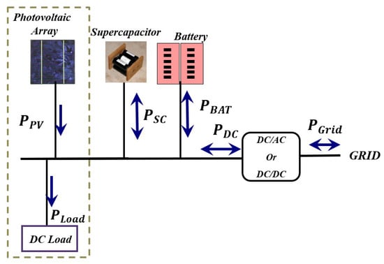
Figure 4.
The Power Flow scheme.
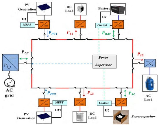
Figure 5.
Ring DC MicroGrid Topology.
In general, the DC MicroGrid is connected to the main AC Grid then , and the balance power is supplied to or obtained from the AC Grid ( being the power from or to the AC grid). In the present paper, we investigate the more difficult case corresponding to when the DC MicroGrid is in islanded mode, and we cannot rely on the AC network to balance the DC grid. In this case, any unbalance on the power flow will create a voltage excursion on the DC grid.
The energy storage elements can switch between charge and discharge mode in order to maintain the DC grid power balance. must be kept around its nominal value and inside voltage limits following the power balance given by Equation (4). It is possible to rewrite Equation (4) as:
In the following, as in (5) is designed for and , in order to steer to its reference using backsteeping techniques [44]. Let us define the output tracking error .
Based on the error dynamics, we suggest the following current reference:
with:
where represents an integral error term, and , and are positive tuning gain parameters.
Due to time-scale consideration between the voltage and current dynamics, in the sequel we consider as a zero dynamics of the system, so can be considered already equal to , such that inside an operation region ( for a desired constant ) and we can write:
As a consequence, the closed-loop dynamics of results in being linear and exponentially stable, with desired dynamics given by the stable poles assigned by the tuning gains. Then, there exists such that , where is the identity matrix in , such that the Lyapunov function:
exists, which time derivative is negative definite:
3. Local Control Level
3.1. Storage System Control
3.1.1. Battery Control Law
Taking the reference value for , it is possible to compute the control law by feedback linearization. First, we define the output tracking error:
and consider the control law [11]:
where is obtained through a derivative filter, represents an integral term and , and are the positive tuning gain parameters. By technological reasons, the following condition is always fulfilled:
Consequently, the closed loop system is shown to be linear and exponentially stable [11]:
3.1.2. Supercapacitor Control Law
We define the output tracking error and its derivative .
As in the previous case, we consider a control law by input/output feedback linearization such as to steer towards its reference , imposing the desired dynamic closed-loop behaviour, where represents an integral error term and , and are the positive tuning gain parameters:
Consequently, the closed loop system results linear and exponentially stable [11]:
We remark that is obtained as in (11), and we need to consider a condition similar to the one in with (12) (always fulfilled by technological reasons):
The control inputs and feedback linearize the dynamics of and . As a result of the linearity of the stable closed loop system, there exist matrices such that , where is an identity matrix in .
Therefore, we introduce the candidate Lyapunov function:
which time derivative is:
3.2. PV System Control
Based on (1), the control target for the PV array is to stabilize the voltage capacitor around the time varying (piecewise constant) reference value , provided by the MPPT algorithm. Similarly to [10], we state the assumption that the current can be set to have much faster dynamics than the capacitances’ voltages. This allows the current and voltage regulation to be in a cascaded control scheme, with an inner current loop and an outer voltage loop. Consequently, a reference for will be designed to steer to its reference . To this purpose, we define the tracking errors:
Then, similarly to [11], we consider the tracking reference as:
and the control law:
where and represent the integral terms assuring zero error in steady state between the dynamics of the states and their references:
and where , , , , and are positive tuning gain parameters. As before, the control input feedback linearizes the dynamics of and , and the closed loop results to be linear and exponentially stable [11]:
As a consequence, there exist matrices such that , is an identity matrix in . Then, we introduce the Lyapunov function for the dynamics of and and its derivative as:
4. Stability Study of the Interconnected System
It is possible to split the states into controlled variables and and the zero dynamics (uncontrolled variables) , , , and . With respect to the equilibrium points given by the references, the calculation of the missing equilibrium points , , , and can be easily performed by steady-state considerations for the closed loop system.
Lemma 1.
Proof.
The proof is based on a Lyapunov function W, which is a composition of the previous Lyapunov functions. We consider the closed loop system with respect to the control inputs , and already defined for controlling the dynamics of , , , and . They were proven to be stable by the Lyapunov functions , and . These Lyapunov functions, provided for each step, will be used for the entire system by a composite Lyapunov function. The Lyapunov function V is then defined as:
where , and have already been introduced and refers to dynamics , , , and . We introduce the errors , , , and between the remaining voltage dynamics and their equilibrium points, and consider a candidate Lyapunov function as:
Its time derivative is:
Finally, we consider the composition of the Lyapunov functions for the whole system:
which time derivative is:
Then, exponential convergence of all states of the interconnected system towards their equilibrium points is ensured. □
5. Simulation Results
In this section we present simulations using detailed switching models on Simscape Electrical from Matlab Simulink (see Table 1 for simulation parameters). These simulations allow to isolate the control and dynamic response phenomena, while still being representative for the remaining power electronic aspects.

Table 1.
Simulation parameters.
Two simulations are presented. The first one is performed in 300 s of simulation time, and aims to show the system power characteristics and energy behavior. The second is performed in 50 s of simulation time, and focuses on the dynamic performance of the proposed control.
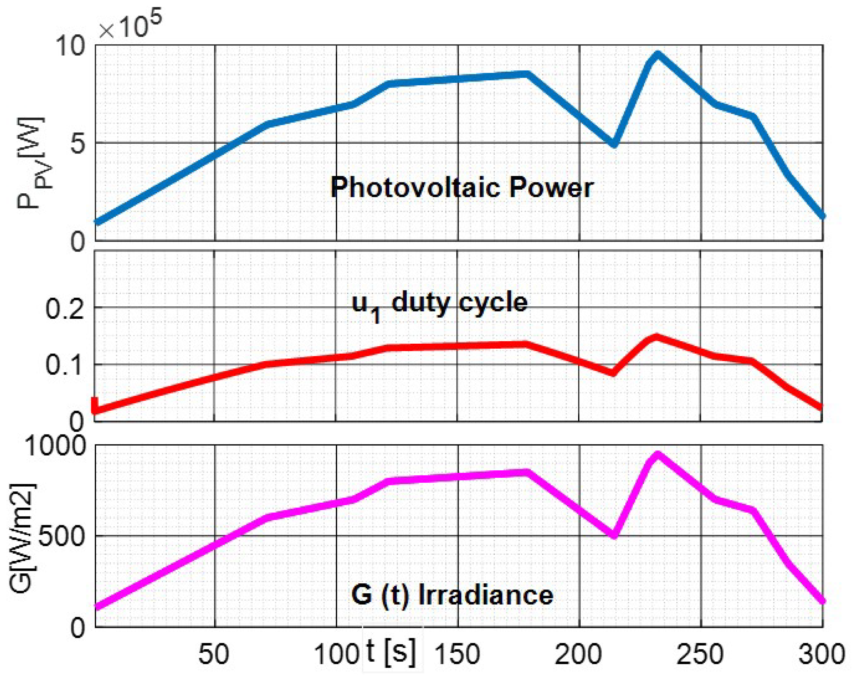
Figure 6 on the left shows the output power for the photovoltaic system with varying irradiance. It can be seen that the output power follows the irradiance variations. Figure 6 on the right shows the control input , which is bounded between zero and 1. One can see that the local controller keeps the PV tracking its Maximum Power Point.
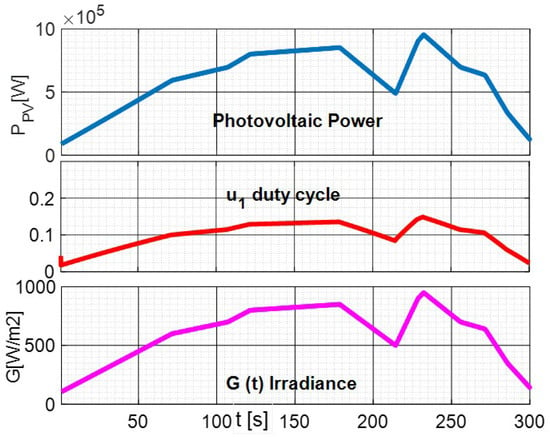
Figure 6.
PV with Varying Irradiance.
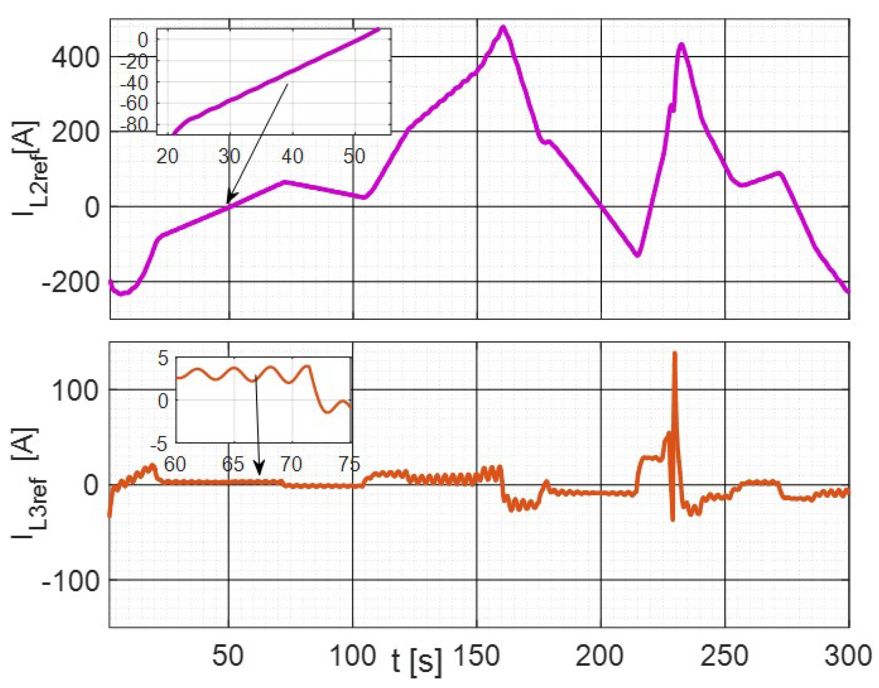
Figure 7 shows the signal decomposition from Equation (5), with fast and slow references shown in the top and the bottom figures, respectively.
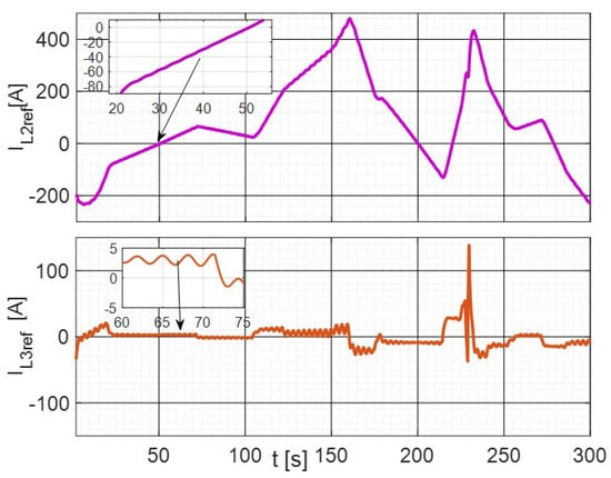
Figure 7.
Power reference components (top graph: , bottom graph: ).
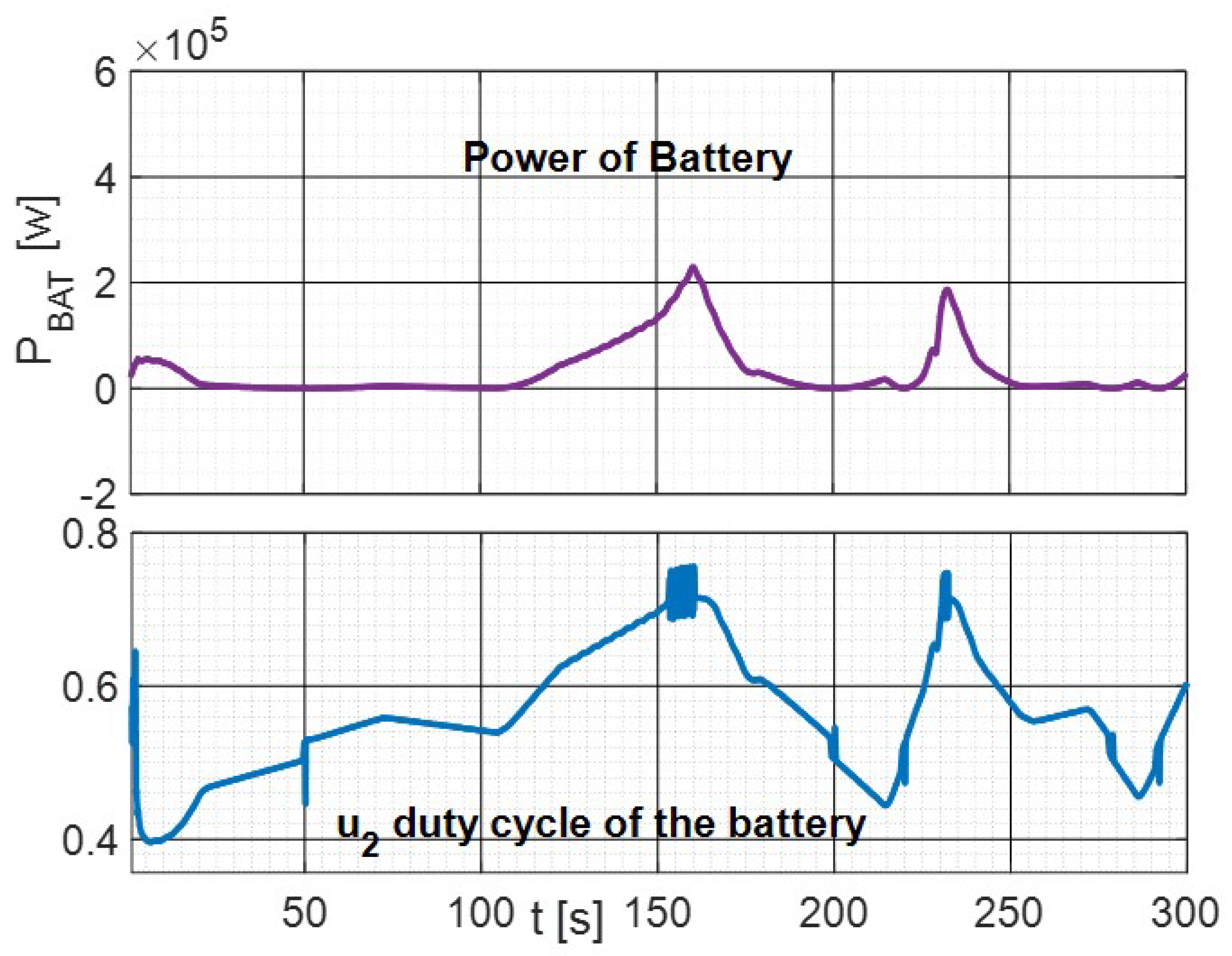
Figure 8 shows the control input which is bounded between zero and one and the output power from the battery.
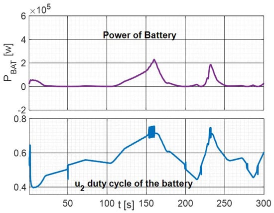
Figure 8.
Control inputs and Output power of the battery.
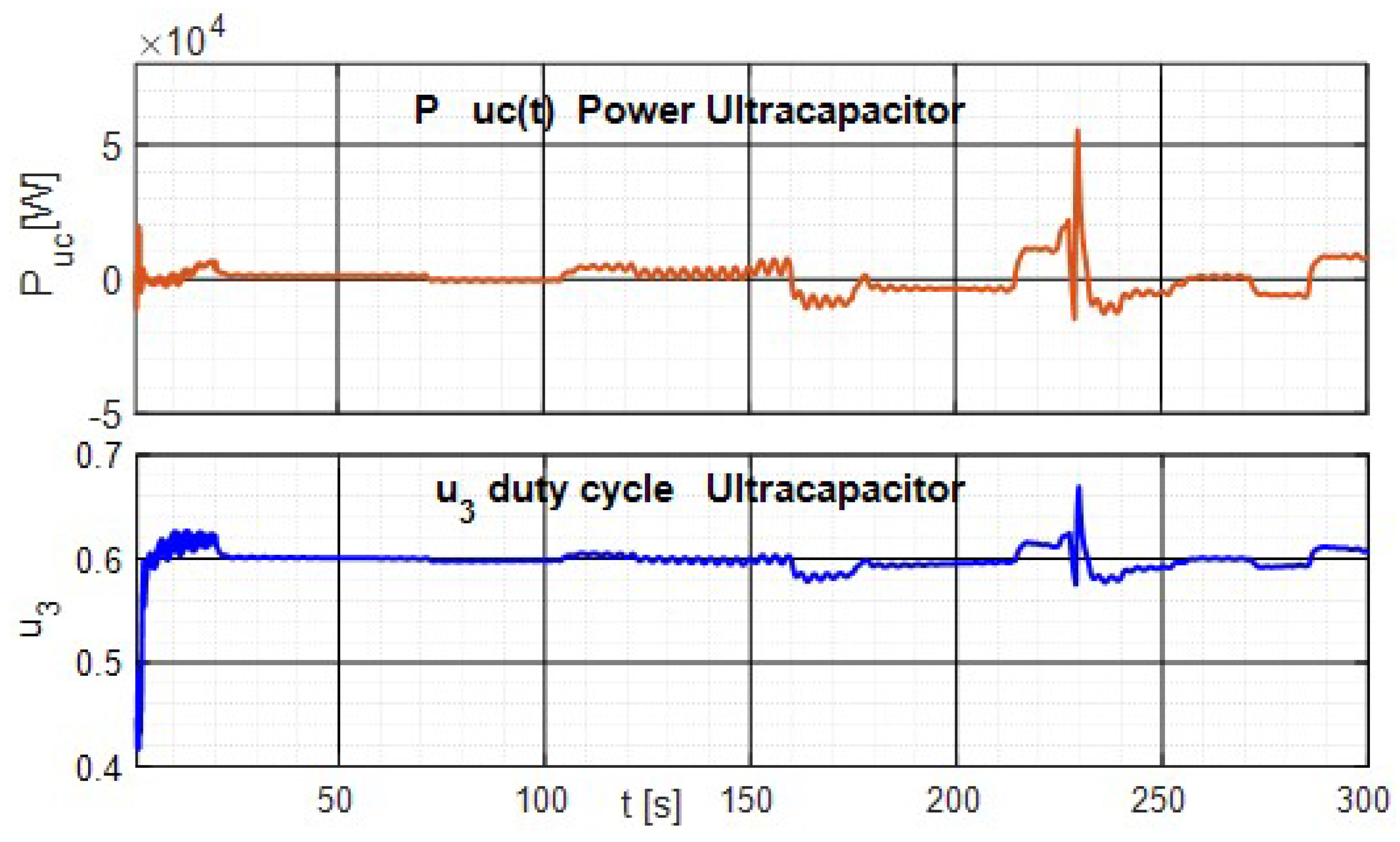
Figure 9 shows the control inputs , which are bounded between zero and one, and the output power from the supercapacitor. The Figure 8 and Figure 9 show the control inputs are smooth except in the case of fast power variations of different elements of the DC MicroGrid. Concerning the output power from the battery and the supercapacitor, fast time-varying signals are instantaneously absorbed by the supercapacitor , such that the battery can remain rather unchanged during fast perturbations. This is capital to ensure a long lifespan for the battery. This one can then provide most of the energy demanded by the load, allowing long-term stability and the use of weather forecast and load predictions in the higher-level algorithms.
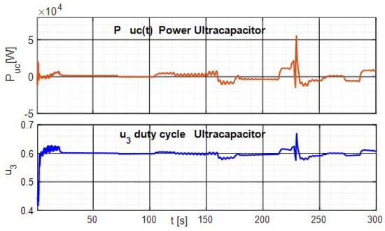
Figure 9.
Control inputs and output power of the supercapacitor.
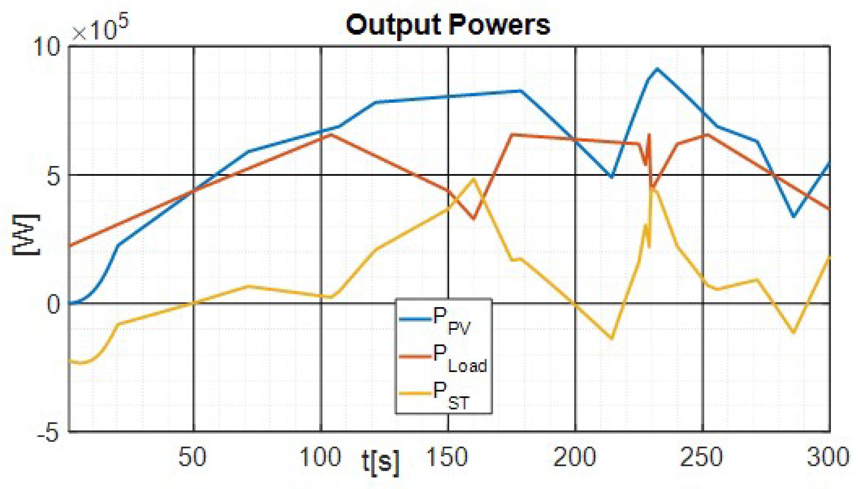
Figure 10 shows the output power for different elements of the DC MicroGrid. We can remark that the variation of storage power follows the variation on PV and load powers, illustrating how grid voltage stabilization is reached by the storage power response.
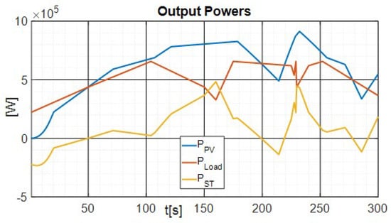
Figure 10.
Output Power.
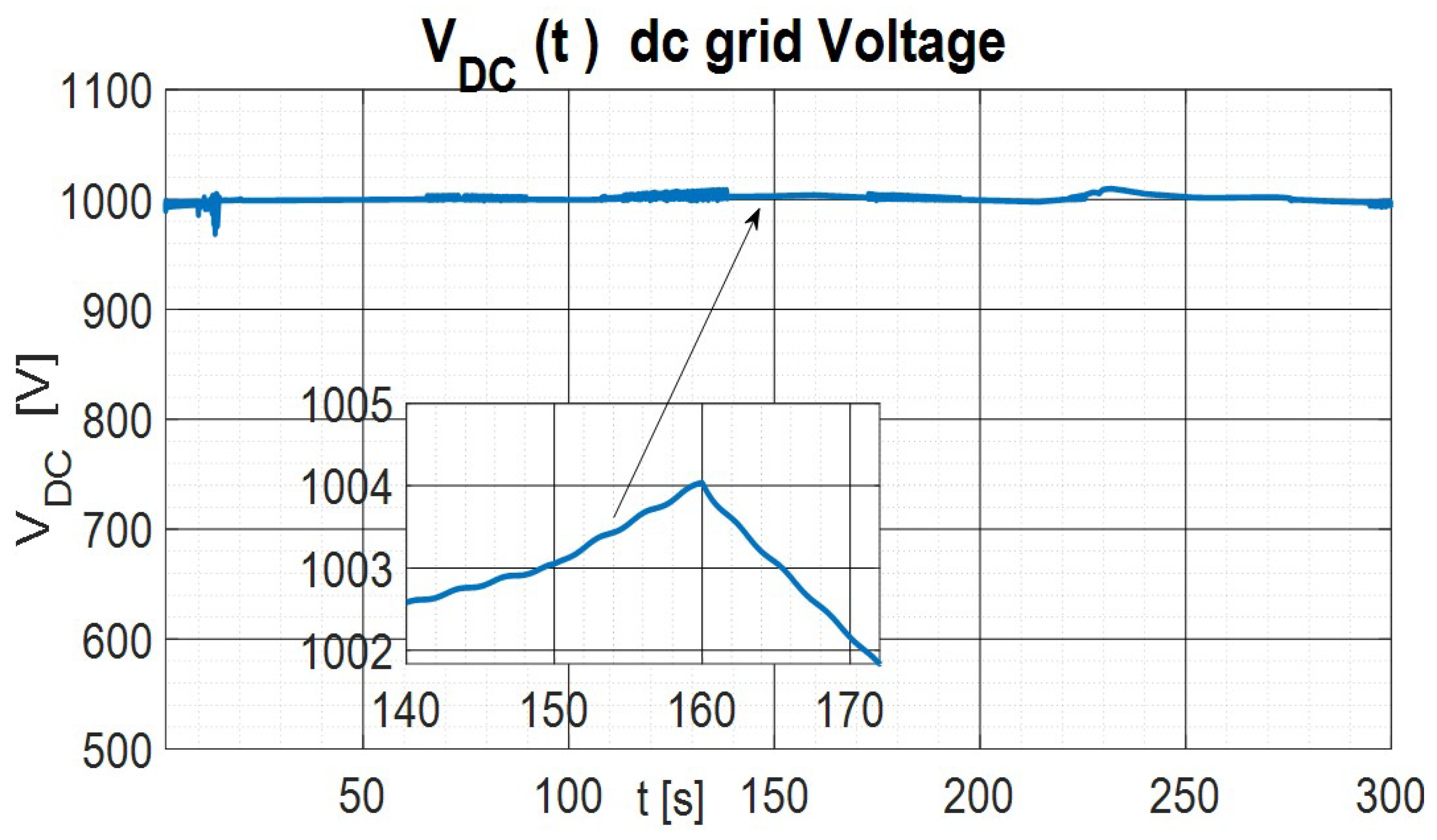
Figure 11 presents the DC voltage response for this longer simulation with slow power excursions. There, one may note that the controller always keeps close to its nominal value despite these large power variations.
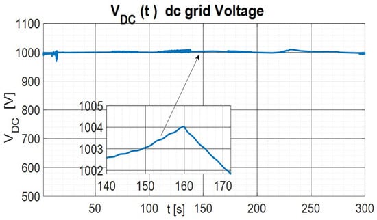
Figure 11.
DC MicroGrid voltage.
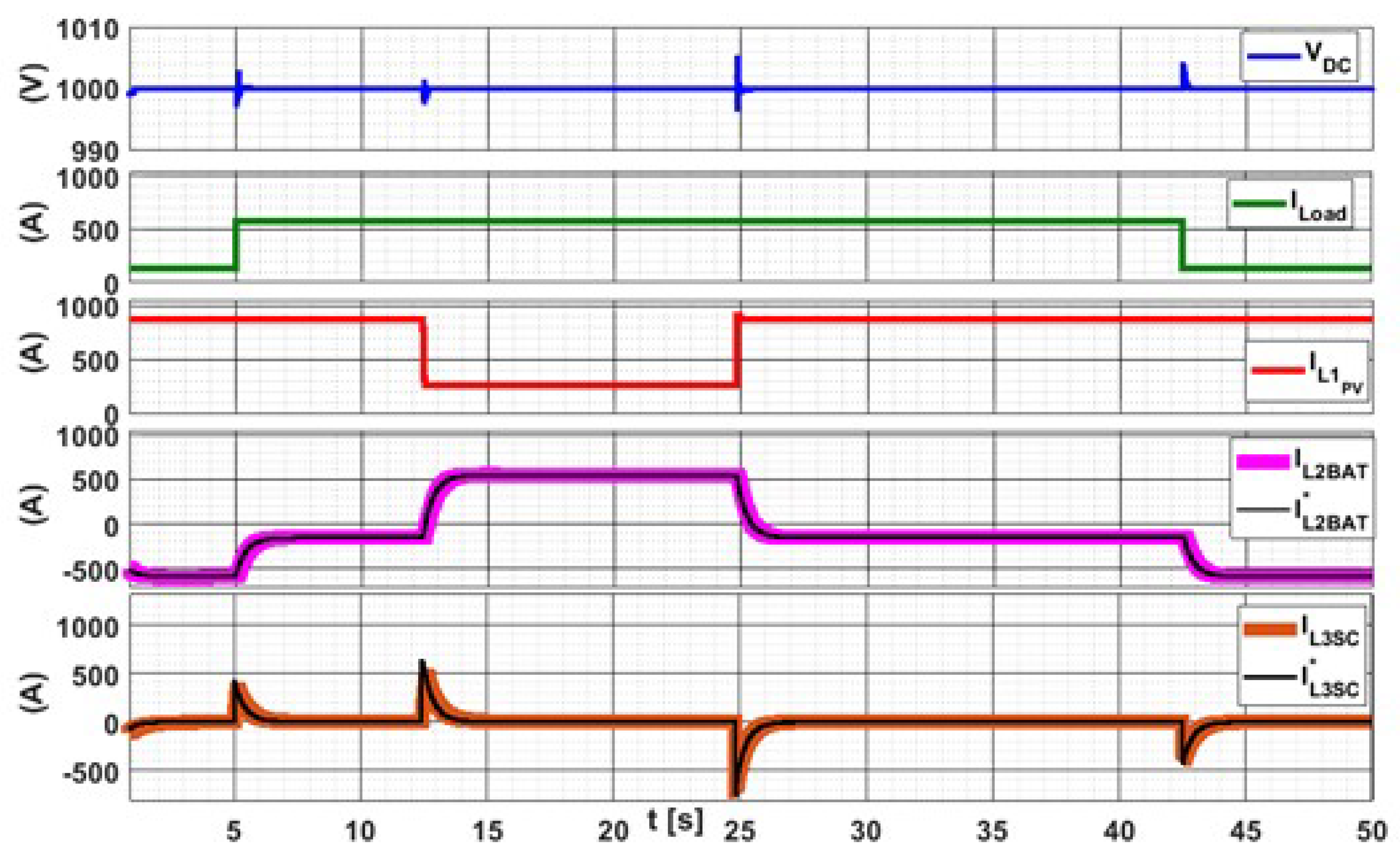
Figure 12 in contrast shows fast (step) load power variations. It can be seen how the DC bus voltage is kept stable inside its operation region, despite the fast variations on load and PV currents. The load current is equal to 576 A for 5 s 42.8 s and is equal to 138 A elsewhere. The solar irradiance is kept at 1000 W/m2 for 12.4 s and from 24.8 s it is set to 300 W/m2. One can notice very small DC bus voltage variations following the transients, quickly recovering and stabilizing at the rated (1000 V DC) in about 10 ms. The maximum DC bus voltage error equals 4 V = 0.4%, well inside the desired operation region.
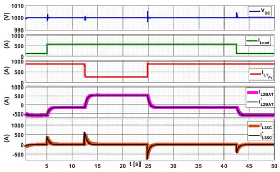
Figure 12.
Dynamic response of the system.
The reference and actual waveforms for the battery are shown in the fourth screen from the top. Reference signal varies slowly for the battery, resulting in very small errors. The reference and actual waveforms for the supercapacitor are shown in the fifth screen from the top. This reference varies much faster due to PV generation and load demand variations, returning to 0 A after each transitory.
These results confirm that the proposed scheme is effective in achieving the goals defined for this application.
Comparison with PI Control
To illustrate the performance of the proposed controller, this one is compared to the industrial standard PI control. The global objective is to stabilize the DC voltage as fast as possible.
State space averaging method is used to obtain a Small Signal model for the converter ([45,46,47]). The model is formulated under the assumption that all the converter elements are ideal. The PI controllers are designed similarly to the ones presented in [48,49,50,51,52].
In general, the DC MicroGrid is connected to the main AC Grid and then , and balance power is supplied to or obtained from the AC Grid. In our work we study the more difficult case when the DC MicroGrid is in islanded mode, and we cannot rely on the AC network to balance the DC grid. In this case, any unbalance on power flow will create a voltage excursion on the DC grid.
From Equation (6) we define the dynamic equation of voltage of DC MicroGrid:
The energy storage elements can switch between charge and discharge mode in order to maintain the DC grid power balance. must be kept near its nominal value and inside voltage limits following the power balance.
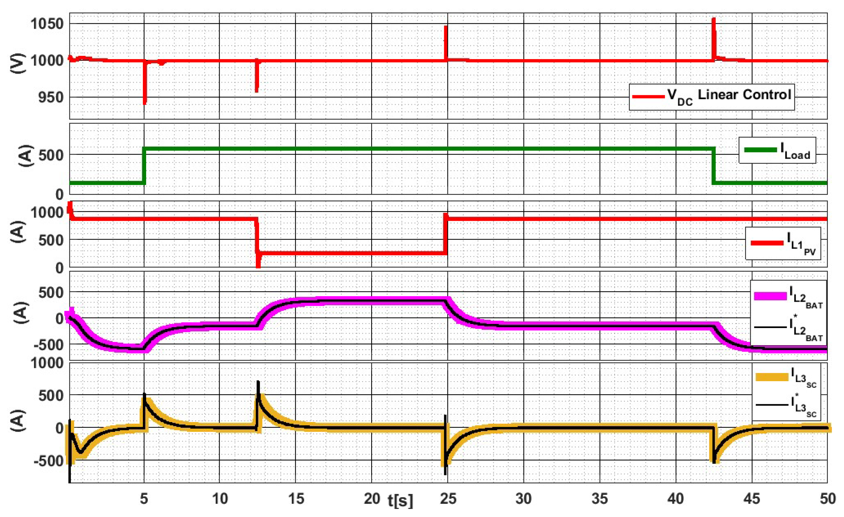
To present a performance comparison of the proposed controller, Figure 13 shows the results for the same simulation as above using the industrial standard, a linear control (PI) for the DC MicroGrid voltage. The first picture of Figure 13 shows how the DC bus voltage (top) varies as the load current and PV current (following screens) vary. The load current is equal to 576 A for 5 s < t < 42.8 s and is equal to 138 A elsewhere. The solar irradiance was rated as 1000 W/m2 for 12.4 s and 24.8 s, and is equal to 300 W/m2 otherwise. There, one sees that the DC bus voltage varies briefly following the transients, recovering and stabilizing at the rated DC bus voltage of 1000 V DC in about 1 s. The maximum DC bus voltage error is equal to 58 V. The battery’s reference and actual waveforms are shown on the fourth screen from the top. The reference signal varies slowly and the actual waveform follows it with a small switching frequency ripple.
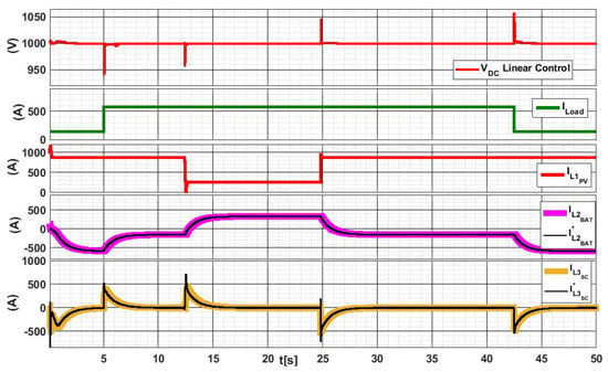
Figure 13.
dynamics applying classical PI linear control.
The supercapacitor’s reference and actual waveforms are shown on the last screen from the top. The reference signal varies fast and the actual waveform follows it to cope with the generation and load variations, converging to 0 A in steady state. One can also note that the PI linear control response has bigger overshoots in transients and slower response.
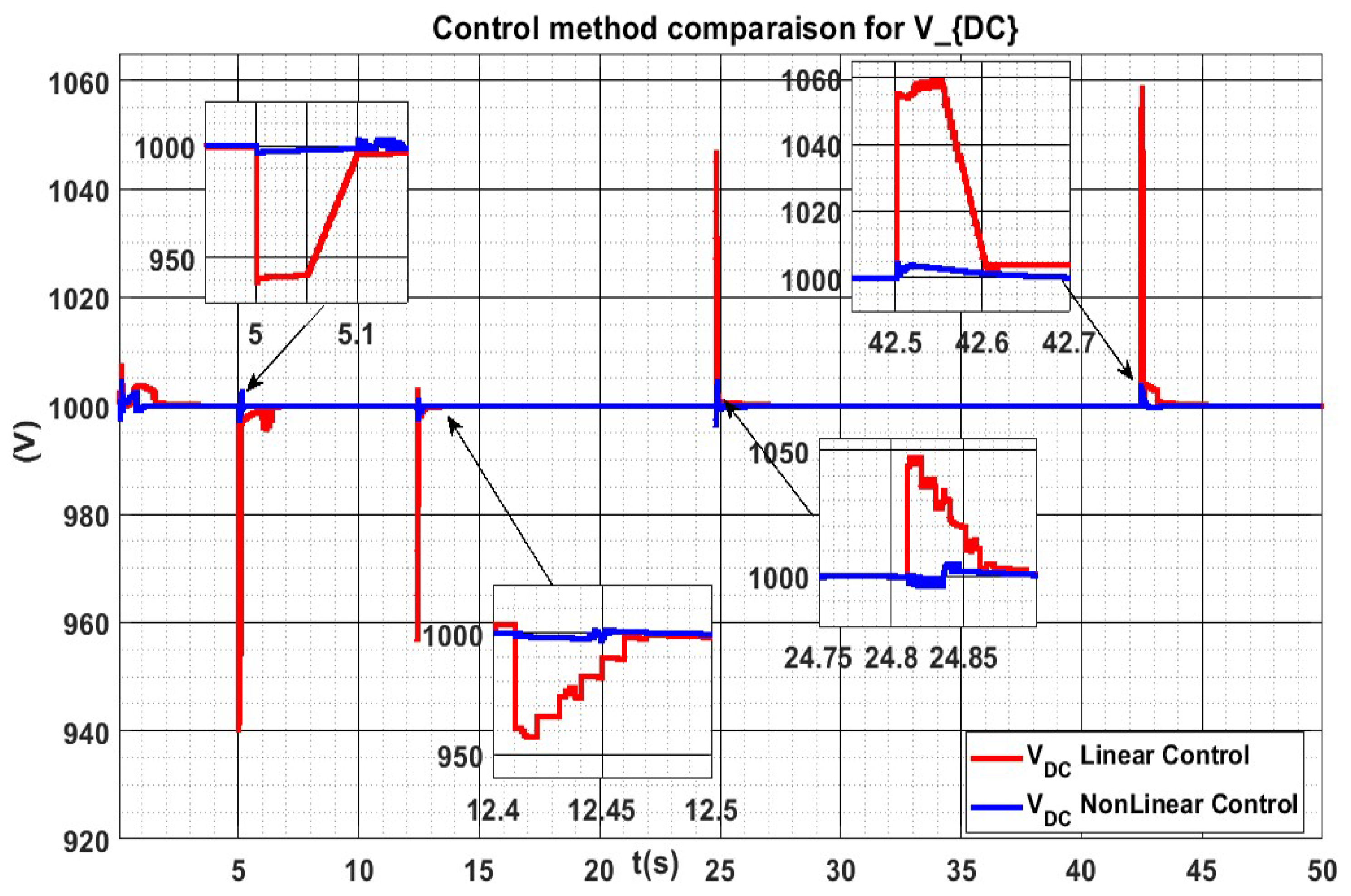
Figure 14 presents a comparative study for the DC MicroGrid voltage. It can be seen that the DC bus voltage varies following each disturbance, recovering and stabilizing at the rated (1000 V). The maximum DC bus voltage error is equal to 55 V for linear control in red. By using the PI linear control, the voltage oscillates during 1.2 s before reaching steady state, while the steady-state response for the proposed nonlinear control is reached at 10 ms as designed (it could be chosen to be faster though).
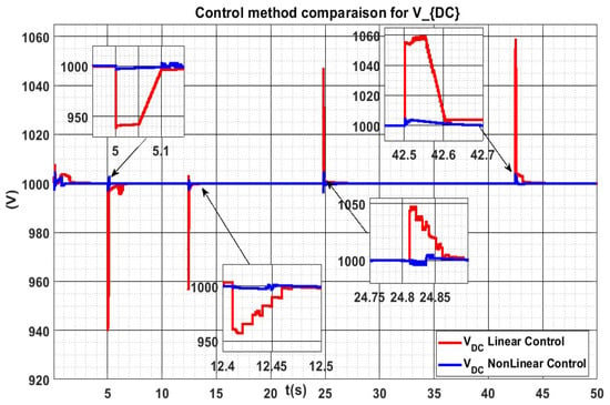
Figure 14.
Comparison of the dynamics by applying nonlinear control (in blue) and classical PI control (in red).
Table 2 shows a comparison of voltage overshoot and settling time for several step changes in load demand and photovoltaic power. There, one may remark that the nonlinear control has a much smaller overshoot () than the linear PI. In the same way, settling time is much faster for the nonlinear control.

Table 2.
Performance comparison with linear control and nonlinear control.
6. Conclusions
The efficient integration of distributed renewable power sources, especially fast intermittent sources such as solar power, is an essential but difficult task. It depends on developing flexible integration strategies to the network.
In this paper, a DC MicroGrid composed of PV panels and storage devices evolving at different time scales is considered to favor this integration, and controllers for each element are designed. A hierarchical control strategy is proposed such that it absorbs the maximum available renewable power while keeping the DC grid’s voltage stable with respect to variations due to power production and consumption. The proposed control algorithm splits the power reference into fast and slow components, to be tracked by the supercapacitor and the battery, respectively. As a consequence, the storage devices keep the DC voltage at the desired value and guarantee the balance between power generation and consumption. Moreover, in order to guarantee a suitable lifespan for the battery, the control strategy respects physical constraints.
Detailed simulation results corroborate our claims, and illustrate the good behavior of each element and the overall interconnected system. Compared to other results in the literature, this paper focuses on proposing easily implementable control algorithms, based on physical characteristics of the grid’s elements, in order to obtain desired closed-loop dynamics and a formal stability proof. Future works will be dedicated to implementation in test-beds and the extension of the result to more complex meshed DC grids.
Author Contributions
S.B.S., A.I., G.D., L.G.-D. and M.N. have participated in the development of the scientific results and the writing of the paper. All authors have read and agreed to the published version of the manuscript.
Funding
This research received no external funding.
Conflicts of Interest
The authors declare no conflict of interest.
Nomenclature
| Output current of solar cell | |
| Output power of solar cell | |
| Terminal voltage of PV cell | |
| Output current of the battery | |
| Output voltage of the battery | |
| Output power of the battery | |
| Output current of the super capacitor | |
| Output voltage of the super capacitor | |
| Output power of the super capacitor | |
| Output power of the DC microgrid | |
| T | Cell’s reference Temperature |
| G | Solar irradiation |
| State of charge of battery | |
| , | internal resistances of DC/DC converter for the PV |
| , | resistances of DC/DC converter for the PV |
| inductance for the boost converter for the PV | |
| capacitance of DC/DC converter for the PV | |
| , | Voltage of capacitance and of DC/DC converter for the PV |
| current of inductance for the boost converter for the PV | |
| , | internal resistances of DC/DC converter for the battery |
| , | resistances of DC/DC converter for the battery |
| inductance for the boost converter for the battery | |
| capacitance of DC/DC converter for the battery | |
| , | Voltage of capacitance and of DC/DC converter for the battery |
| current of inductance for the boost converter for the battery | |
| , | internal resistances of DC/DC converter for the super capacitor |
| , | resistances of DC/DC converter for the super capacitor |
| inductance for the boost converter for the super capacitor | |
| capacitance of DC/DC converter for the super capacitor | |
| , | Voltage of capacitance and of DC/DC converter for the super capacitor |
| current of inductance for the boost converter for the super capacitor | |
| DC-link capacitance of DC micro grid | |
| f | Frequency of the AC grid |
| cutoff frequency for the filter | |
| … | positive tuning gains parameters |
| , and | Duties cycle of DC/DC converter |
References
- Hatziargyriou, N. Microgrids: Architectures and Control; John Wiley and Sons: Hoboken, NJ, USA, 2014. [Google Scholar]
- Bevrani, H.; Francois, B.; Ise, T. Microgrid Dynamics and Control; John Wiley and Sons Inc.: Hoboken, NJ, USA, 2017. [Google Scholar]
- Ongaro, F.; Saggini, S.; Mattavelli, P. Li-Ion Battery-Supercapacitor Hybrid Storage System for a Long Lifetime, Photovoltaic-Based Wireless Sensor Network. IEEE Trans. Power Electron. 2012, 27, 3944–3952. [Google Scholar] [CrossRef]
- Tahim, A.P.N.; Pagano, D.J.; Lenz, E.; Stramosk, V. Modeling and Stability Analysis of Islanded DC Microgrids under Droop Control. IEEE Trans. Power Electron. 2015, 30, 4597–4607. [Google Scholar] [CrossRef]
- Dulout, J.; Jammes, B.; Seguier, L.; Alonso, C. Control and design of a hybrid energy storage system. In Proceedings of the 2015 17th European Conference on Power Electronics and Applications (EPE 15 ECCE-Europe), Geneva, Switzerland, 8–10 September 2015; pp. 1–9. [Google Scholar]
- O’Keeffe, D.; Riverso, S.; Albiol-Tendillo, L.; Lightbody, G. Distributed Hierarchical Droop Control of Boost Converters in DC Microgrids. In Proceedings of the 28th IEEE Irish Signals & Systems Conference, Killarney, Ireland, 20–21 June 2017. [Google Scholar]
- Liang, C.; Zhang, Y.; Ji, X.; Meng, X.; An, Y.; Yao, Q. DC Bus Voltage Sliding-mode Control for a DC Microgrid Based on Linearized Feedback. In Proceedings of the 2019 Chinese Automation Congress (CAC), Hangzhou, China, 22–24 November 2019; pp. 5380–5384. [Google Scholar] [CrossRef]
- Kollimalla, S.K.; Mishra, M.K.; Narasamma, N.L. Design and Analysis of Novel Control Strategy for Battery and Supercapacitor Storage System. IEEE Trans. Sustain. Energy 2014, 5, 1137–1144. [Google Scholar] [CrossRef]
- Ferreira, R.A.F.; Barbosa, P.G.; Braga, H.A.; Ferreira, A.A. Analysis of non-linear adaptive voltage droop control method applied to a grid connected DC microgrid. In Proceedings of the 2013 Brazilian Power Electronics Conference, Gramado, Brazil, 27–31 October 2013; pp. 1067–1074. [Google Scholar] [CrossRef]
- Chen, Y.; Damm, G.; Benchaib, A.; Netto, M.; Lamnabhi-Lagarrigue, F. Control Induced Explicit Time-Scale Separation to Attain DC Voltage Stability for a VSC-HVDC Terminal. IFAC Proc. Vol. 2014, 47, 540–545. [Google Scholar] [CrossRef] [Green Version]
- Iovine, A.; Siad, S.B.; Damm, G.; De Santis, E.; Di Benedetto, M.D. Nonlinear Control of a DC MicroGrid for the Integration of Photovoltaic Panels. IEEE Trans. Autom. Sci. Eng. 2017, 14, 524–535. [Google Scholar] [CrossRef] [Green Version]
- Siad, S.B.; Malkawi, A.; Damm, G.; Lopes, L.; Dol, L.G. Nonlinear control of a DC MicroGrid for the integration of distributed generation based on different time scales. Int. J. Electr. Power Energy Syst. 2019, 111, 93–100. [Google Scholar] [CrossRef] [Green Version]
- Siad, S.; Damm, G.; Dol, L.G.; Bernardinis, A.d. Design and Control of a DC Grid for Railway Stations. In Proceedings of the PCIM Europe 2017, International Exhibition and Conference for Power Electronics, Intelligent Motion, Renewable Energy and Energy Management, Shanghai, China, 27–29 June 2017; pp. 1–8. [Google Scholar]
- Guerrero, J.M.; Loh, P.C.; Lee, T.; Chandorkar, M. Advanced Control Architectures for Intelligent Microgrids—Part II: Power Quality, Energy Storage, and AC/DC Microgrids. IEEE Trans. Ind. Electron. 2013, 60, 1263–1270. [Google Scholar] [CrossRef] [Green Version]
- Carrizosa, M.J.; Navas, F.D.; Damm, G.; Lamnabhi-Lagarrigue, F. Optimal power flow in multi-terminal HVDC grids with offshore wind farms and storage devices. Int. J. Electr. Power Energy Syst. 2015, 65, 291–298. [Google Scholar] [CrossRef]
- Carrizosa, M.J.; Arzandé, A.; Navas, F.D.; Damm, G.; Vannier, J. A control strategy for multi-terminal DC grids with renewable production and storage devices. IEEE Trans. Sustain. Energy 2018, 9, 930–939. [Google Scholar] [CrossRef]
- Siad, S. DC MicroGrids Control for Renewable Energy Integration. Ph.D. Thesis, University Evry, Évry-Courcouronnes, France, 2019. [Google Scholar]
- Iovine, A.; Siad, S.; Damm, G.; De Santis, E.; Di Benedetto, M.D. Nonlinear Control of an AC-connected DC MicroGrid. In Proceedings of the 42nd Annual Conference of the IEEE Industrial Electronics Society—IECON 2016, Florence, Italy, 24–27 October 2016. [Google Scholar]
- Iovine, A.; Carrizosa, M.J.; Damm, G.; Alou, P. Nonlinear Control for DC MicroGrids enabling Efficient Renewable Power Integration and Ancillary Services for AC grids. IEEE Trans. Power Syst. 2019, 34, 5136–5146. [Google Scholar] [CrossRef]
- Iovine, A.; Rigaut, T.; Damm, G.; De Santis, E.; Di Benedetto, M.D. Power management for a DC MicroGrid integrating renewables and storages. Control Eng. Pract. 2019, 85, 59–79. [Google Scholar] [CrossRef]
- Benchaib, A. Advanced Control of AC/DC Power Networks: System of Systems Approach Based on Spatio-Temporal Scales; Wiley-ISTE: London, UK, 2015. [Google Scholar]
- Lee, J.; Han, B.; Choi, N. DC micro-grid operational analysis with detailed simulation model for distributed generation. In Proceedings of the 2010 IEEE Energy Conversion Congress and Exposition, Atlanta, GA, USA, 12–16 September 2010; pp. 3153–3160. [Google Scholar]
- Krajacic, G.; Duic, N.; Mathiesen, B.V.; Carvalho, M.G. Smart energy storages for integration of renewable in 100% independent energy systems. Chem. Eng. Trans. 2010, 21, 391–396. [Google Scholar]
- Yahya, A.M.; Mahmoud, A.; Youm, L. Etude et modellisation d’un generateur photovoltaique. Rev. Energ. Renouvelables 2008, 11, 473–483. [Google Scholar]
- Sera, D.; Teodorescu, R.; Hantschel, J.; Knoll, M. Optimized Maximum Power Point Tracker for fast changing environmental conditions. In Proceedings of the 2008 IEEE International Symposium on Industrial Electronics, Cambridge, UK, 30 June–2 July 2008; pp. 2401–2407. [Google Scholar]
- Xiao, W. A Modified Adaptive Hill Climbing Maximum Power Point Tracking (MPPT) Control Method for Photovoltaic Power Systems. Ph.D. Thesis, University of British Columbia Library, Vancouver, BC, Canada, 2003. [Google Scholar]
- Bacha, S.; Munteanu, I.; Bratcu, A.I. Power Electronic Converters Modeling and Control: With Case Studies; Advanced Textbooks in Control and Signal Processing; Springer: London, UK, 2013. [Google Scholar]
- Merdassi, A.; Gerbaud, L.; Seddik, B. General Average Modelling for Power Electronics Systems: Automatic Building Approach. In Proceedings of the 9th International Conference on Modeling and Simulation of Electric Machines, Converters and Systems, Quebec, QC, Canada, 26–28 May 2008. [Google Scholar]
- Merdassi, A. La Modellisation Automatique Pour l’Electronique de Puissance; Editions Universitaires Europeennes: Chisinau, Moldova, 2010. [Google Scholar]
- Sanders, S.R.; Noworolski, J.M.; Liu, X.Z.; Verghese, G.C. Generalized averaging method for power conversion circuits. IEEE Trans. Power Electron. 1991, 6, 251–259. [Google Scholar] [CrossRef] [Green Version]
- Barton, J.; Infield, D. Energy storage and its use with intermittent renewable energy. IEEE Trans. Energy Convers. 2004, 19, 441–448. [Google Scholar] [CrossRef]
- Bhatia, R.S.; Singh, B.; Jain, D.K.; Jain, S.P. Battery Energy Storage System Based Power Conditioner for Improved Performance of Hybrid Power Generation. In Proceedings of the 2008 Joint International Conference on Power System Technology and IEEE Power India Conference, New Delhi, India, 12–15 October 2008; pp. 1–6. [Google Scholar]
- Gergaud, O.; Robin, G.; Multon, B.; Ahmed, H. Energy Modeling of a Lead-Acid Battery within Hybrid Wind/Photovoltaic Systems. In Proceedings of the European Power Electronic Conference 2003, Toulouse, France, 2–4 September 2003. [Google Scholar]
- Vairamohan, B. State of Charge Estimation for Batteries. Master’s Thesis, University of Tennessee, Knoxville, TN, USA, 2002. [Google Scholar]
- Miller, J.M.; Nebrigic, D.; Everett, M. Ultra Capacitor Distributed Model Equivalent Circuit for Power Electronic Circuit Simulation; Ansoft Leading Insights Workshop; Maxwell Technologies Inc.: San diego, CA, USA, 2006. [Google Scholar]
- Lifshitz, D.; Weiss, G. Optimal control of a capacitor-type energy storage system. IEEE Trans. Autom. Control 2015, 60, 216–220. [Google Scholar] [CrossRef]
- Odo, P. A Comparative Study of Single-phase Non-isolated Bidirectional dc-dc Converters Suitability for Energy Storage Application in a dc Microgrid. In Proceedings of the 2020 IEEE 11th International Symposium on Power Electronics for Distributed Generation Systems (PEDG), Dubrovnik, Croatia, 28 September–1 October 2020; pp. 391–396. [Google Scholar] [CrossRef]
- Sun, J.; Lin, W.; Hong, M.; Loparo, K.A. Voltage Regulation of DC-Microgrid with PV and Battery. IEEE Trans. Smart Grid 2020, 11, 4662–4675. [Google Scholar] [CrossRef]
- Adhikari, S.; Li, F. Coordinated V-f and P-Q Control of Solar Photovoltaic Generators with MPPT and Battery Storage in Microgrids. IEEE Trans. Smart Grid 2014, 5, 1270–1281. [Google Scholar] [CrossRef]
- Manandhar, U.; Ukil, A.; Gooi, H.B.; Tummuru, N.R.; Kollimalla, S.K.; Wang, B.; Chaudhari, K. Energy Management and Control for Grid Connected Hybrid Energy Storage System under Different Operating Modes. IEEE Trans. Smart Grid 2019, 10, 1626–1636. [Google Scholar] [CrossRef]
- Chen, Y.; Jiménez Carrizosa, M.; Damm, G.; Lamnabhi-Lagarrigue, F.; Li, M.; Li, Y. Control-Induced Time-Scale Separation for Multiterminal High-Voltage Direct Current Systems Using Droop Control. IEEE Trans. Control Syst. Technol. 2019, 28, 967–983. [Google Scholar] [CrossRef]
- Fei, Y.; Zhuang, J.; Li, G.; Yao, L.; Yang, B. Research on the dual-terminal ring topology-based dc microgrid system. J. Eng. 2018, 2019, 3255–3258. [Google Scholar] [CrossRef]
- Kumar, D.; Zare, F.; Ghosh, A. DC Microgrid Technology: System Architectures, AC Grid Interfaces, Grounding Schemes, Power Quality, Communication Networks, Applications, and Standardizations Aspects. IEEE Access 2017, 5, 12230–12256. [Google Scholar] [CrossRef]
- Khalil, H. Nonlinear Systems; Pearson: London, UK, 2002. [Google Scholar]
- Jin, Y.; Xu, J.; Zhou, G.; Mi, C. Small-signal modeling and analysis of improved digital peak current control of boost converter. In Proceedings of the 2009 IEEE 6th International Power Electronics and Motion Control Conference, Wuhan, China, 17–20 May 2009; pp. 326–330. [Google Scholar]
- Tang, W.; Lee, F.C.; Ridley, R.B. Small-signal modeling of average current-mode control. IEEE Trans. Power Electron. 1993, 8, 112–119. [Google Scholar] [CrossRef]
- Sun, J.; Bass, R.M. Modeling and practical design issues for average current control. In Proceedings of the Fourteenth Annual Applied Power Electronics Conference and Exposition (APEC ’99), Dallas, TX, USA, 14–18 March 1999; Volume 2, pp. 980–986. [Google Scholar]
- Cherati, S.M.; Azli, N.A.; Ayob, S.M.; Mortezaei, A. Design of a current mode PI controller for a single-phase PWM inverter. In Proceedings of the 2011 IEEE Applied Power Electronics Colloquium (IAPEC), Johor Bahru, Malaysia, 18–19 April 2011; pp. 180–184. [Google Scholar]
- Dixon, L.H. Average Current Mode Control of Switching Power Supplies. In Unitrode Power Supply Design Seminar Manual; Unitrode Corporation: Merrimack, MA, USA, 1990. [Google Scholar]
- Khalid, M. A Review on the Selected Applications of Battery-Supercapacitor Hybrid Energy Storage Systems for Microgrids. Energies 2019, 12, 4559. [Google Scholar] [CrossRef] [Green Version]
- Kollimalla, S.K.; Mishra, M.K.; Ukil, A.; Gooi, H.B. DC Grid Voltage Regulation Using New HESS Control Strategy. IEEE Trans. Sustain. Energy 2017, 8, 772–781. [Google Scholar] [CrossRef]
- Manandhar, U.; Tummuru, N.R.; Kollimalla, S.K.; Ukil, A.; Beng, G.H.; Chaudhari, K. Validation of Faster Joint Control Strategy for Battery- and Supercapacitor-Based Energy Storage System. IEEE Trans. Ind. Electron. 2018, 65, 3286–3295. [Google Scholar] [CrossRef]
Publisher’s Note: MDPI stays neutral with regard to jurisdictional claims in published maps and institutional affiliations. |
© 2022 by the authors. Licensee MDPI, Basel, Switzerland. This article is an open access article distributed under the terms and conditions of the Creative Commons Attribution (CC BY) license (https://creativecommons.org/licenses/by/4.0/).

