Article

Performance Investigation on Mono-Block-Layer Build Type Solid Oxide Fuel Cells with a Vertical Rib Design

School of Energy and Power, Jiangsu University of Science and Technology, Zhenjiang 212003, China
*
Author to whom correspondence should be addressed.
Energies 2022, 15(3), 979; https://doi.org/10.3390/en15030979
Submission received: 18 December 2021 / Revised: 20 January 2022 / Accepted: 26 January 2022 / Published: 28 January 2022
(This article belongs to the Special Issue Hydrogen and Fuel Cell Technology, Modelling and Simulation)

Abstract

:
Compared with planar-type solid oxide fuel cells (SOFCs), mono-block-layer build (MOLB)-type SOFCs have additional three-phase boundaries per unit volume, and their performance is severely limited by their longer current path. To resolve this issue, a vertical rib design, which was evaluated using a numerical method, was proposed. Compared with the conventional design, the power density for the vertical rib design increased by 12.32%. This is because the vertical rib design provides another short path for current, which not only reduces the ohmic loss in the cathode, but also decreases the ohmic polarization caused by the contact resistance. However, the vertical rib design hinders the transport of oxygen in the cathode and increases the concentration loss. Therefore, the vertical rib size design is crucial. Based on the influence of the vertical rib width, the vertical rib widths on the cathode and anode sides of 0.7 and 1 mm are recommended for different contact resistances, respectively.

1. Introduction

Fuel cells have attracted widespread attention from international scholars owing to their high efficiency, cleanliness, and quietness [1,2,3,4]. At present, the relatively mature fuel cell technology is the proton exchange membrane fuel cell (PEMFC), and its application fields include automobiles, forklifts, submarines, and unmanned aerial vehicles. However, PEMFCs use precious metals as catalysts, which increases the production costs. In addition, high-purity hydrogen is required, and the storage and transportation of hydrogen is a major problem, which hinders the commercial application of PEMFCs [5,6,7]. Compared with the PEMFCs, solid oxide fuel cells (SOFCs) can use non-noble metals as catalysts because of their higher operating temperatures (873.15–1073.15 K). In view of this, SOFC technology has developed rapidly in recent years [8,9,10,11]. The SOFC is an all-solid structure, and thus it is more convenient to made into various structural forms. Based on the structure, the SOFC can be divided into planar type, tubular type, micro tubular type and mono-block-layer build (MOLB) type [12,13,14,15]. Conversely, owing to its corrugated anode/electrolyte/cathode, the MOLB-type type SOFC increases the total length of the three-phase boundaries and reduces the activation polarization, while the corrugated anode/electrolyte/cathode provides the fuel and air flow channel, eliminating the interconnector channel and making the SOFC more compact [16].
In recent years, many scholars have used numerical simulation methods to study the effects of various parameters and design schemes on the performance of MOLB-type SOFCs. Yang et al. established an MOLB-type SOFC model to analyze the effects of co-flow and counter-flow designs on temperature and current density, and found that the co-flow design has a more uniform temperature and current density distribution [17]. Zhang et al. compared and analyzed the difference in heat and mass conduction between planar-type SOFCs and MOLB-type SOFCs. Under the same working conditions, the temperature gradient of the MOLB-type SOFC is smaller than that of the planar-type SOFC, and the temperature distribution of the planar-type SOFC is more sensitive to the fuel flow rate and hydrogen mass fraction [18]. Verda et al. optimized the geometric structure parameters of the MOLB-type SOFCs to minimize entropy production. The simulation results suggest that compared with the initial design, the power density of the optimized structure has increased by approximately 11% [19]. Mendoza-Miranda et al. discussed the influence of electrolyte thickness, inlet temperature, inlet velocity, and inlet mass fraction on entropy production. The results indicate that the irreversible entropy generation is closely related to the inlet temperature and electrolyte thickness. When the inlet temperature was 973 K, the overall entropy production was approximately 35% less than when the inlet temperature was 873 K [20,21]. Stygar et al. studied the influence of the MOLB-type SOFCs geometry on the temperature distribution and heat conduction rate. It was found that two adjacent layers were cross-flow, and when one layer was counter-flow, the temperature was more uniform and the temperature gradient was smaller [22]. Mendoza-Miranda et al. considered the internal reforming of methane on the anode side and found that compared with planar-type SOFCs, MOLB-type SOFCs have higher H2 concentrations and lower average temperatures [23].
In the author’s previous work, the influence of anode thickness, cathode thickness, channel height, and porosity on the performance of MOLB-type SOFCs, was investigated [12]. The study found that when the cathode thickness is 100 μm and the working voltage is 0.7 V, the cathode ohmic polarization is as high as 70 mV, accounting for 17.5% of the total polarization loss of the SOFC. To reduce the ohmic polarization in the cathode, in this study, we proposed a vertical rib design, as shown in Figure 1. In addition, the difference between the conventional design and the vertical rib design was compared and analyzed, and then the effects of the vertical rib width design on the performance of the MOLB-type SOFC were studied. Finally, the optimization of the vertical rib width for different contact resistances is discussed.

2. Model

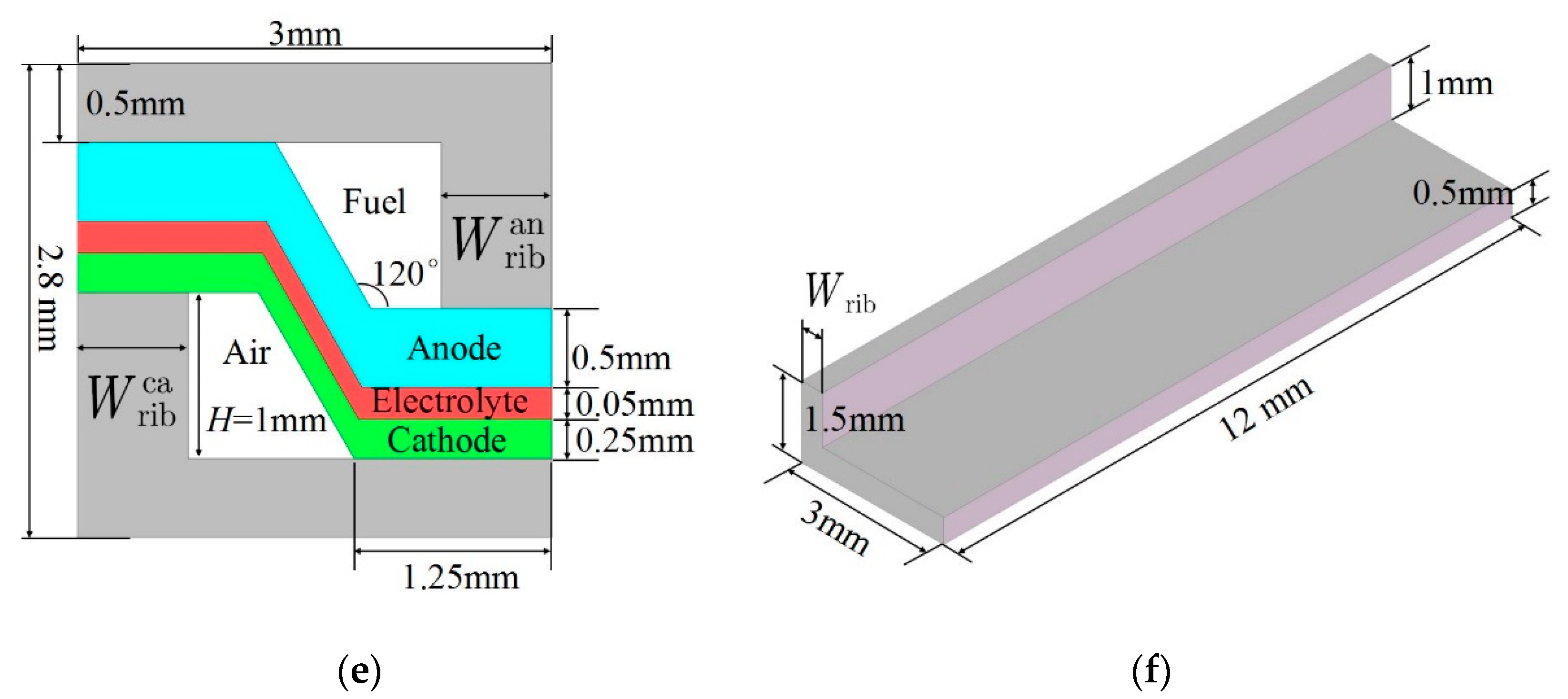
To shorten the simulation time, the simulation domain in this work is a repeating unit, as shown in Figure 1c,d including the interconnector (Stainless Steel), anode (Ni/YSZ), cathode (LSM/YSZ), and electrolyte (YSZ). The structural dimensions are shown in Figure 1e. The vertical rib design model is based on the conventional design model established in our previous work [12] by adding vertical ribs, and the contact resistance was set at the interface between the vertical rib and the electrode. The model is briefly introduced below, and its governing equations are listed in Table 1. To solve the governing equations, appropriate boundary conditions must be set. The gas concentration and inlet volume flow rate were set at the channel inlet. The open-circuit voltage was set on the external surface of the anode side interconnector. The working voltage was set on the external interconnector surface of the cathode side, and the conversion current was set at the interface between the electrode and the electrolyte, as shown in Table 2. Except for the settings in Table 2, for the momentum equation, the other boundaries are no-slip, which means the normal velocity is zero; for the species equation, there is no mass flux across the other boundaries; for the charge equation, electric insulation is set on the other boundaries.
The conversion current at the anode/electrolyte interface can be written as:
i trans an = i ref an exp [ E H 2 R ( 1 T 1 T ref ) ] ( p H 2 TPB p H 2 O TPB p H 2 0 p H 2 O 0 ) × [ exp ( 2 α f an F R T η act an ) exp ( 2 β r an F R T η act an ) ]
The conversion current at the cathode/electrolyte can be written as:
i trans ca = i ref ca exp [ E O 2 R ( 1 T 1 T ref ) ] ( p O 2 TPB p O 2 0 ) 0.25 × [ exp ( 2 α f ca F R T η act ca ) exp ( 2 β r ca F R T η act ca ) ]
The activation polarization of the anode can be written as:
η act an = Φ el Φ io R T 2 F ln ( p H 2 0 p H 2 O 0 p H 2 O TPB p H 2 TPB )
The activation polarization of the cathode can be written as:
η act ca = Φ io Φ el R T 4 F ln ( p O 2 0 p O 2 TPB )
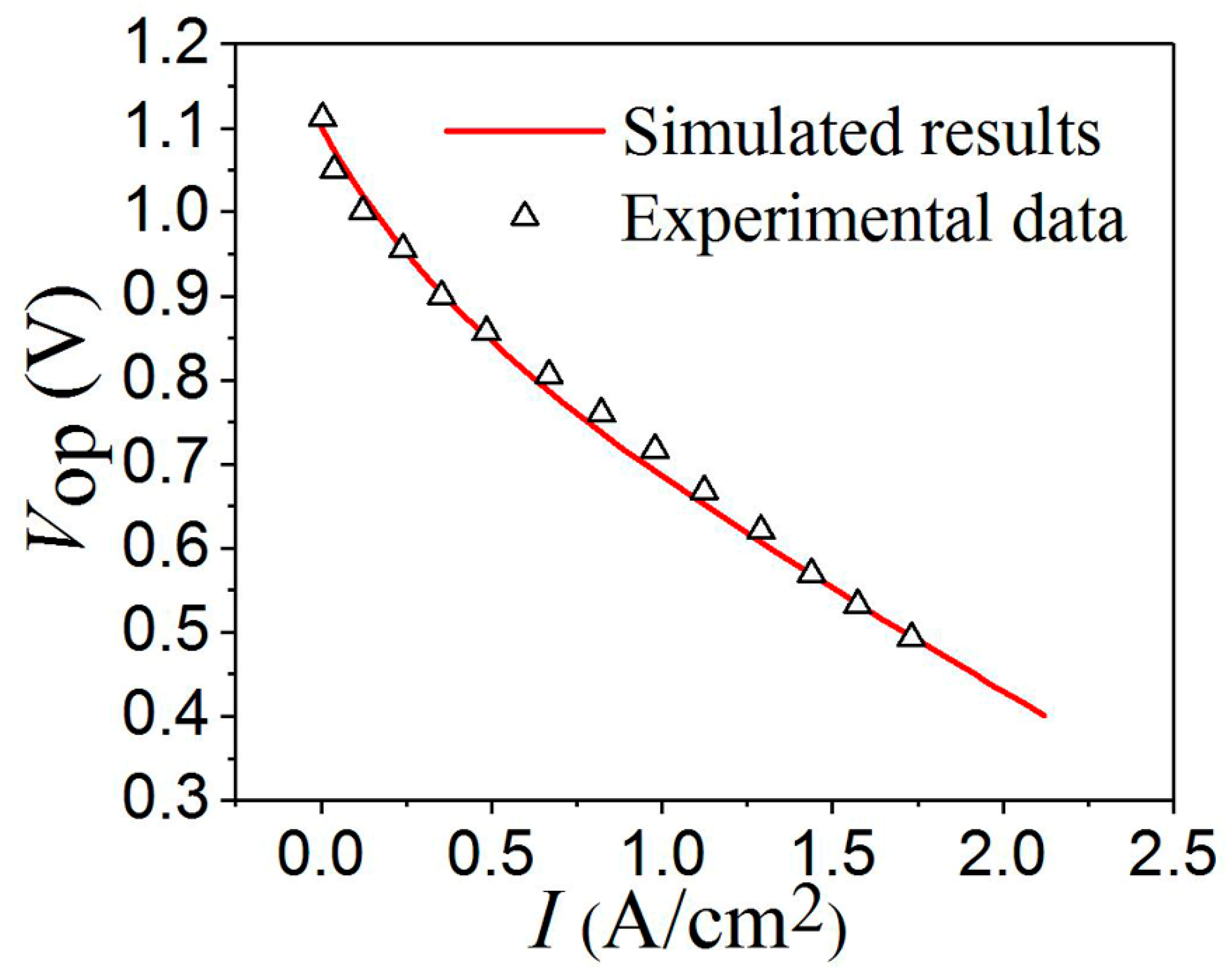
This study uses Comsol Multiphisics software to establish the MOLB-type SOFC model, and the model parameters are listed in Table 3. First, the grid independence is verified for vertical rib design. Figure 2 shows grid diagrams with different grid numbers. When the number of grids was 46,200, the power density per unit volume was 1.5502 W/cm3, which was 1.5501 W/cm3 for 77,000 grids. Therefore, 46,200 grids are sufficient, and the following numerical simulation uses this grid setting. To validate the model, the button cell model is built with the settings as described above except for the component thickness. The anode thickness, cathode thickness, and electrolyte thickness of the button cell model are 500, 30, and 25 mm, respectively, according to experimental conditions in Ref [24]. Figure 3 shows a comparison between the experimental data [24] and model calculation results. It can be observed that the model calculation results are consistent with the experimental data.

3. Results and Discussion

3.1. Ohmic Polarization

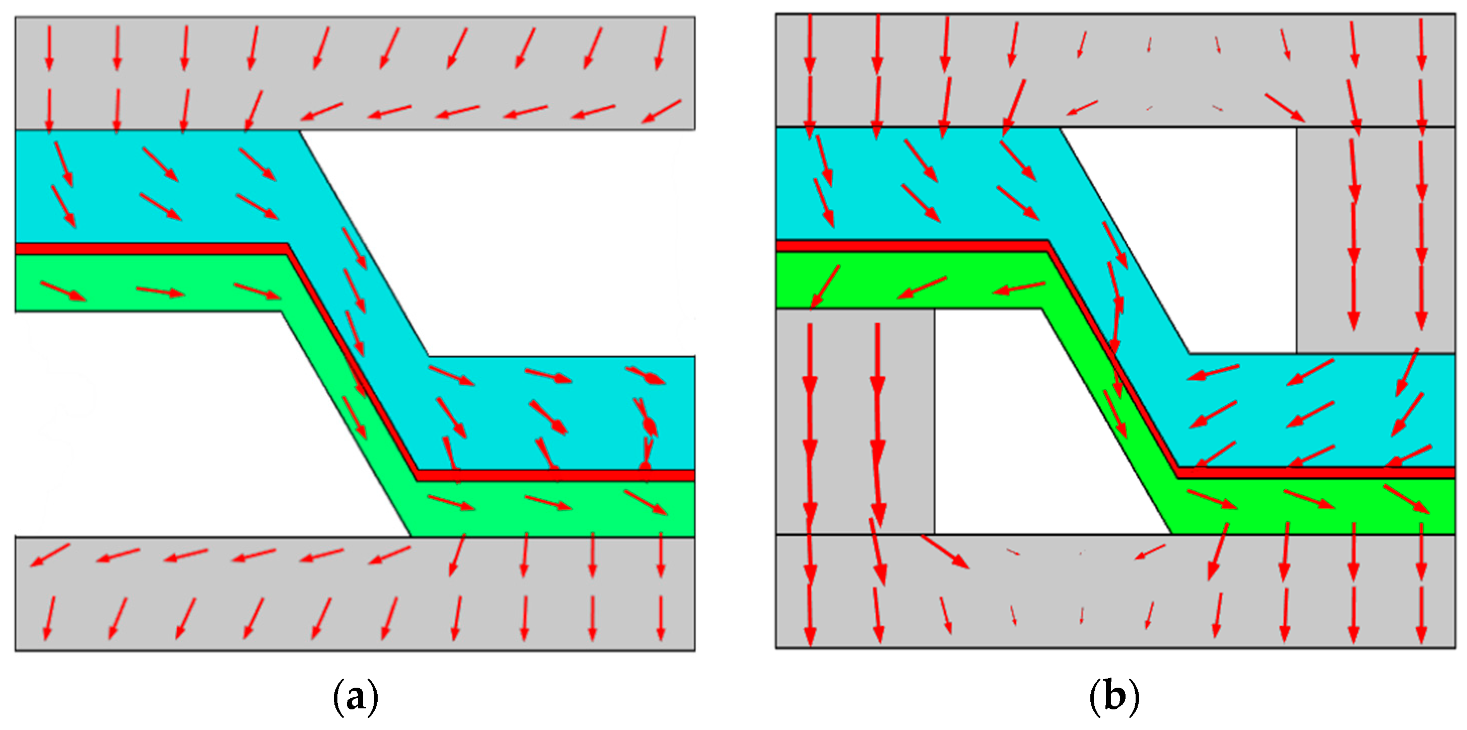
To reduce the ohmic polarization in the cathode, a vertical rib design was proposed. The results show that the power density for the vertical rib design is 1.55 W/cm3, which increases by 12.32% from the power density of 1.38 W/cm3 for the conventional design. The advantage of vertical rib design can be understood by analyzing the ohmic polarization. Figure 4 compares the cathode potential distributions of the conventional and vertical rib designs. The potential distribution is similar for the two designs, with a high potential on the left and a low potential on the right. This is because the current flows from the anode through the electrolyte to the cathode, as shown in Figure 5. In addition, the cathode ohmic polarization in the conventional design is 34.3 mV (=770 mV − 735.7 mV), while it is only 15.2 mV (=738.4 mV − 723.2 mV) for the vertical rib design, which is 55.7% less than the conventional design. This is because the vertical rib design provides another short path for the current and reduces the ohmic loss in the cathode.
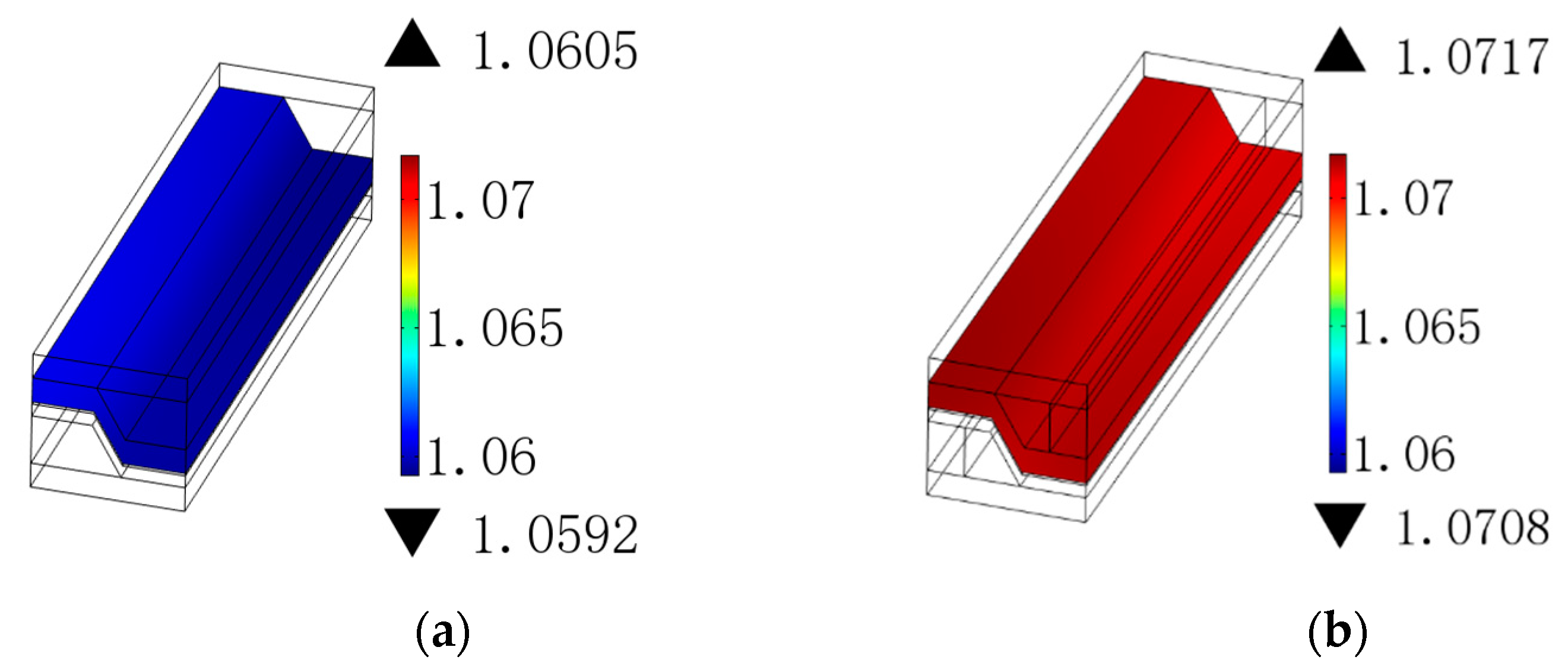
Figure 6 shows the potential distribution of the anodes for the two designs. Compared with the cathode, the potential change in the anode is small, which is mainly because the conductivity of the anode is much greater than that of the cathode. Owing to the generation of oxides, the interface between the interconnector and the electrode has a large contact resistance. The voltage on the upper surface of the anode interconnector is 1.1 V, and the potential loss in the interconnector is negligible owing to its relatively large electrical conductivity. Therefore, the ohmic polarization caused by the anode contact resistance of the conventional design is 39.5 mV (=1.1 V − 1.0605 V), which is 28.3 mV (=1.1 V − 1.0717 V) for the vertical rib design, showing a decrease of 28.4% compared with the conventional design. The ohmic polarization caused by the cathode contact resistance is reduced from 35.7 mV (=0.7357 V − 0.7 V) in the conventional design to 23.2 mV (=0.7232 V − 0.7 V) in the vertical rib design, showing a decrease of 35%. This is because the vertical rib design reduces the current density at the interface between the interconnector and the electrode by providing another current path, which reduces the ohmic polarization caused by the contact resistance. Therefore, the vertical rib design not only reduces the ohmic polarization in the cathode but is also beneficial to the reduction in the ohmic polarization caused by the contact resistance.

3.2. Gas Concentration Distribution

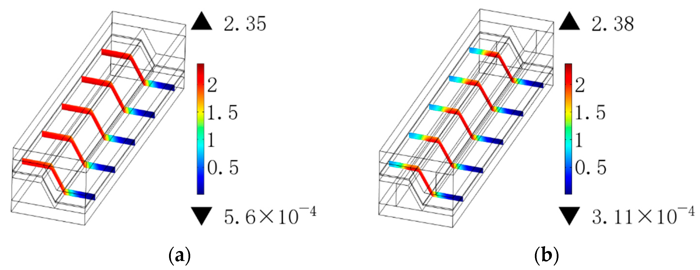
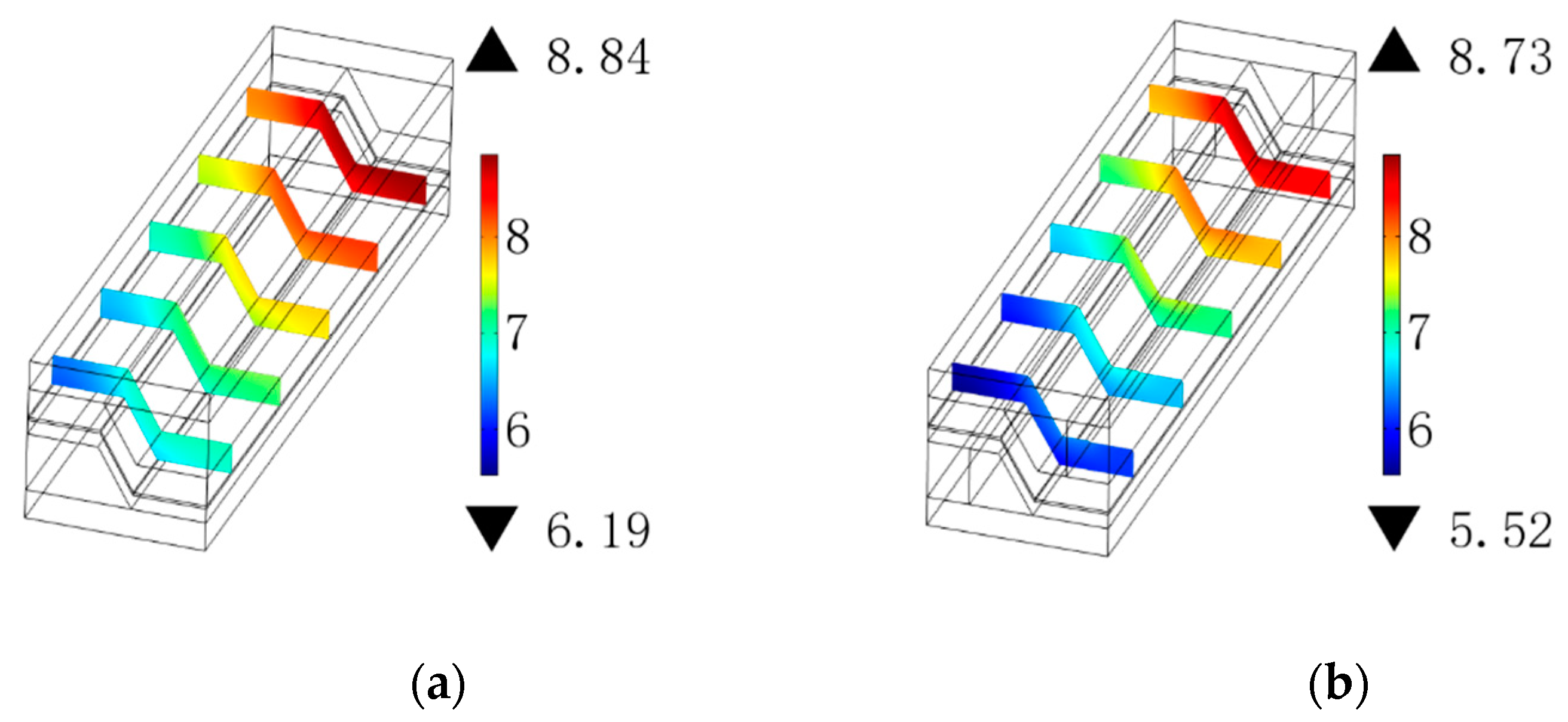
Figure 7 shows the oxygen concentration distributions for the two designs. For both designs, the contact region between the interconnector and the cathode impedes the diffusion of oxygen in the cathode, resulting in a low oxygen concentration region, which decreases the SOFC performance. In addition, comparing Figure 7a,b it was found that the vertical rib also hindered the transport of oxygen in the cathode. On the one hand, the vertical rib design reduces the ohmic polarization, but it increases the concentration loss. Therefore, the vertical rib size design is crucial. The hydrogen concentration distributions are shown in Figure 8. The effects of the contact region between the interconnector and anode on hydrogen can be neglected. This is mainly because the anode thickness is thicker, which reduces the diffusion resistance of hydrogen in the horizontal direction.

3.3. Vertical Rib Width

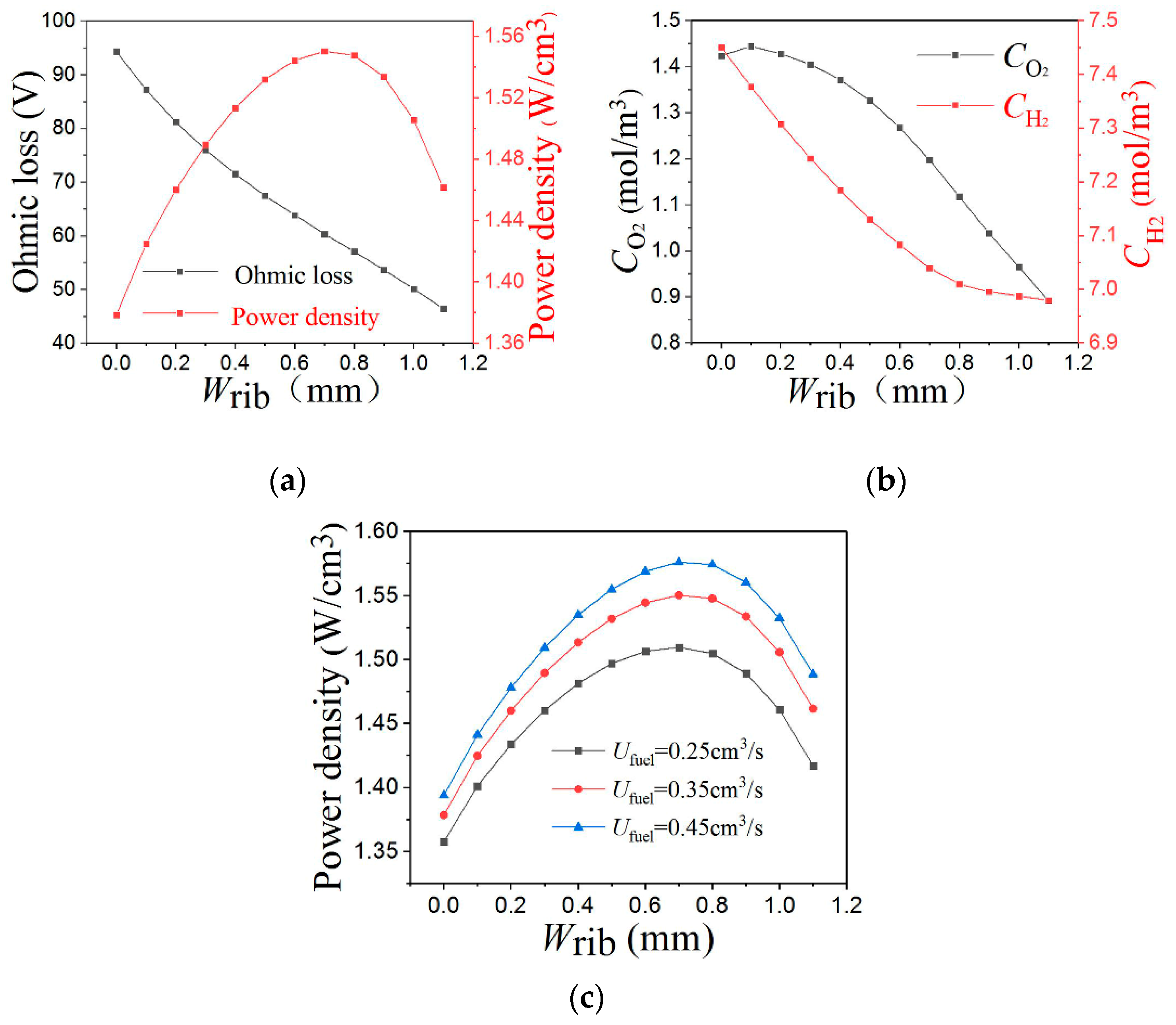
As shown in Figure 9, ohmic loss (ohmic loss = cathode ohmic polarization + ohmic polarization introduced by anode contact resistance + ohmic polarization introduced by cathode contact resistance) gradually decreases with an increase in the vertical rib width (Wrib), whereas the power density increases first and then decreases, reaching the maximum value when the vertical rib width (Wrib) is 0.7 mm. This is because an increase in the vertical rib width reduces the oxygen concentration in the cathode. For example, when the vertical rib width (Wrib) increases from 0.1 to 0.7 mm, the average oxygen concentration in the cathode is decreased by 16.67% from 1.44 to 1.20 mol/m3. However, hydrogen is decreased by only 4.61% from 7.38 to 7.04 mol/m3, as shown in Figure 9b. Therefore, the vertical rib design has a weak impact on hydrogen but has a greater impact on oxygen. Thus, it is expected that the optimal vertical rib width on the cathode side ( W rib ca ) would be smaller than the optimal vertical rib width on the anode side ( W rib an ). Furthermore, although with the increase in the inlet gas volume flow, the performance of SOFC is enhanced for a fixed rib width, the effect of inlet gas volume flow on the optimal vertical rib width is negligible, as shown in Figure 9c.
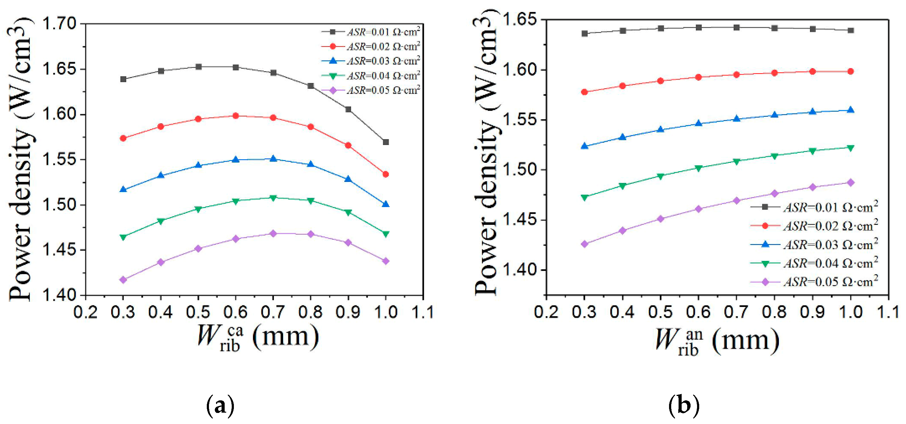
As mentioned above, the vertical rib design has an obvious effect on the ohmic polarization caused by the contact resistance. It is necessary to investigate the influence of the vertical rib width with different contact resistances as the contact resistance gradually increases with time. Figure 10a shows the relationship between the vertical rib width on the cathode side ( W rib ca ) and the power density when the vertical rib width on the anode side ( W rib an ) is 0.7 mm. The greater the contact resistance, the lower the output power density. In addition, it can be observed that the smaller the contact resistance, the smaller the optimal W rib ca . For example, when the contact resistance is 0.01 Ω cm2, the optimal W rib ca is 0.55 mm, and when the contact resistance is 0.05 Ω cm2, the optimal W rib ca is 0.75 mm. Note that the variation in the power density is small near the optimal W rib ca . Thus, an W rib ca of 0.7 mm is recommended for different contact resistances.
Figure 10b shows the relationship between the vertical rib width on the anode side ( W rib an ) and the power density for different anode contact resistances when the W rib ca is 0.7 mm. As the W rib an increases, it is beneficial to reduce the ohmic polarization caused by the contact resistance on the anode side, but this has little effect on the hydrogen concentration. Therefore, a larger W rib an was expected within the design range. However, owing to space constraints, an W rib an of 1 mm is recommended.

4. Conclusions

To reduce the ohmic polarization of MOLB-type SOFCs, a vertical rib design was proposed in this study. A numerical method was adopted to analyze the advantages of the proposed design compared with the conventional design. It was found that the vertical rib design provides another additional short path for the current, reducing the ohmic polarization in the cathode, and simultaneously decreasing the ohmic polarization caused by contact resistance. However, the vertical rib design hinders the transport of oxygen and increases the concentration loss. By analyzing the influence of the vertical rib width on the cathode side ( W rib ca ), the results show that there is an optimal value for W rib ca . Furthermore, because the anode is thicker, the vertical rib width on the anode side W rib an has little effect on the transport of hydrogen. Therefore, a larger W rib an was expected within the design range. However, owing to space constraints, an W rib an of 1 mm is recommended.

Author Contributions

Conceptualization, W.K.; data curation, S.L.; investigation, S.L. and M.Z.; methodology, J.W.; resources, M.Z.; software, J.W.; writing—review and editing, W.K. All authors have read and agreed to the published version of the manuscript.

Funding

This research was funded by the National Science Foundation of China grant number 22179054 and 11774324. And the APC was funded by 22179054.

Institutional Review Board Statement

Not applicable.

Informed Consent Statement

Not applicable.

Data Availability Statement

Not applicable.

Conflicts of Interest

The authors declare no conflict of interest.

Nomenclature

A S R contact Contact resistance, (Ω cm2)
B 0 Permeability coefficient, (m2)
C i 0 Molar concentration of species i at channel inlet, (mol/m3)
C i Molar concentration of species i , (mol/m3)
C p Specific heat capacity, (J/kg)
D i j Binary diffusion coefficient, (m2/s)
D i Kn Knudsen diffusion coefficient of species i , (m2/s)
D i Equivalent diffusion coefficient of species i , (m2/s)
E 0 Nernst potential, (V)
F Faraday constant, (96,487 C/mol)
i el Electronic current density, (A/m2)
i io Ionic current density, (A/m2)
i trans an Local transfer current at anode, (A)
i trans ca Local transfer current at cathode, (A)
M i Molecular mass, (kg/mol)
N i Molar flux, (mol/m2/s)
R Universal gas constant, (J/mol/K)
p Total pressure, (Pa)
p 0 One atmospheric pressure, (Pa)
p i 0 Species i pressure at channel inlet, (Pa)
p i TPB Species i pressure at TPB, (Pa)
r g Pore radii, (m)
T Operating temperature, (K)
T ref Reference temperature, (K)
u Convection velocity, (m/s)
ν i Diffusion volume, (m3/mol)
x i Molar fraction
Φ el Local electronic potential, (V)
Φ io Local ionic potential, (V)
V op Operational potential, (V)
σ el eff Effective conductivity, (S/m)
η act an Anode activation polarization, (V)
η act ca Cathode activation polarization, (V)
ε The porosity
μ Viscosity coefficient of fluid, (Pa·s)
ρ Density, (kg/m3)
τ Tortuosity factor

References

  1. Squizzato, E.; Sanna, C.; Glisenti, A.; Costamagna, P. Structural and Catalytic Characterization of La 0.6 Sr 0.4 MnO3 Nanofibers for Application in Direct Methane Intermediate Temperature Solid Oxide Fuel Cell Anodes. Energies 2021, 14, 3602. [Google Scholar] [CrossRef]
  2. Prokop, T.A.; Brus, G.; Szmyd, J.S. Microstructure Evolution in a Solid Oxide Fuel Cell Stack Quantified with Interfacial Free Energy. Energies 2021, 14, 3576. [Google Scholar] [CrossRef]
  3. Nenning, A.; Bischof, C.; Fleig, J.; Bram, M.; Opitz, A.K. The Relation of Microstructure, Materials Properties and Impedance of SOFC Electrodes: A Case Study of Ni/GDC Anodes. Energies 2020, 13, 987. [Google Scholar] [CrossRef] [Green Version]
  4. Fang, X.R.; Zhu, J.; Lin, Z.J. Effects of Electrode Composition and Thickness on the Mechanical Performance of a Solid Oxide Fuel Cell. Energies 2018, 11, 1735. [Google Scholar] [CrossRef] [Green Version]
  5. Mao, L.; Jackson, L.; Davies, B. Investigation of PEMFC fault diagnosis with consideration of sensor reliability. Int. J. Hydrog. Energy 2018, 43, 16941–16948. [Google Scholar] [CrossRef]
  6. He, K.; Zhang, C.; He, Q.B.; Wu, Q.; Jackson, L.; Mao, L. Effectiveness of PEMFC historical state and operating mode in PEMFC prognosis. Int. J. Hydrog. Energy 2020, 45, 32355–32366. [Google Scholar] [CrossRef]
  7. Chang, K.Y.; Lin, H.J.; Chen, P.C. The optimal performance estimation for an unknown PEMFC based on the Taguchi method and a generic numerical PEMFC model. Int. J. Hydrog. Energy 2009, 34, 1990–1998. [Google Scholar] [CrossRef]
  8. Kong, W.; Han, Z.; Lu, S.; Ni, M. A simple but effective design to enhance the performance and durability of direct carbon solid oxide fuel cells. Appl. Energy 2021, 287, 116586. [Google Scholar] [CrossRef]
  9. Zhu, J.; Lin, Z.J. Degradations of the electrochemical performance of solid oxide fuel cell induced by material microstructure evolutions. Appl. Energy 2018, 231, 22–28. [Google Scholar] [CrossRef]
  10. Kashmiri, S.A.; Tahir, M.W.; Afzal, U. Combustion Modeling and Simulation of Recycled Anode-off-Gas from Solid Oxide Fuel Cell. Energies 2020, 13, 5186. [Google Scholar] [CrossRef]
  11. Kong, W.; Zhang, W.; Huang, H.; Zhang, Y.; Wu, J.; Xu, Y. Analysis of micro-tubular SOFC stability under ambient and operating temperatures. J. Mater. Sci. Technol. 2018, 34, 1436–1440. [Google Scholar] [CrossRef]
  12. Huang, H.Y.; Han, Z.; Lu, S.Y.; Kong, W.; Wu, J.; Wang, X.R. The analysis of structure parameters of MOLB type solid oxide fuel cell. Int. J. Hydrog. Energy 2020, 45, 20351–20359. [Google Scholar] [CrossRef]
  13. Fu, Q.R.; Li, Z.Y.; Wei, W.; Liu, F.X.; Xu, X.F.; Liu, Z.J. Performance enhancement of a beam and slot interconnector for anode-supported SOFC stack. Energy Convers. Manag. 2021, 241, 114277. [Google Scholar] [CrossRef]
  14. Kong, W.; Han, Z.; Lu, S.Y.; Gao, X.; Wang, X.R. A novel interconnector design of SOFC. Int. J. Hydrog. Energy 2020, 45, 20329–20338. [Google Scholar] [CrossRef]
  15. Altan, T.; Celik, S. Effect of surface roughness of the metallic interconnects on the bonding strength in solid oxide fuel cells. Int. J. Hydrog. Energy 2020, 45, 35118–35129. [Google Scholar] [CrossRef]
  16. Hwang, J.; Chen, C.; Lai, D. Computational analysis of species transport and electrochemical characteristics of a MOLB-type SOFC. J. Power Sources 2005, 140, 235–242. [Google Scholar] [CrossRef]
  17. Yang, Y.; Wang, G.; Zhang, H.; Xia, W. Computational analysis of thermo-fluid and electrochemical characteristics of MOLB-type SOFC stacks. J. Power Sources 2007, 173, 233–239. [Google Scholar] [CrossRef]
  18. Yang, Y.; Wang, G.; Zhang, H.; Xia, W. Comparison of heat and mass transfer between planar and MOLB-type SOFCs. J. Power Sources 2008, 177, 426–433. [Google Scholar] [CrossRef]
  19. Sciacovelli, A.; Verda, V. Entropy Generation Minimization in a Tubular Solid Oxide Fuel Cell. J. Energy Resour. Technol. Trans. Asme 2010, 132, 012601. [Google Scholar] [CrossRef]
  20. Ramírez-Minguela, J.J.; Uribe-Ramírez, A.R.; Mendoza-Miranda, J.M.; Pérez-García, V.; Rodríguez-Muñoz, J.L.; Minchaca-Mojica, J.I.; Alfaro-Ayala, J.A. Study of the entropy generation in a SOFC for different operating conditions. Int. J. Hydrog. Energy 2016, 41, 8978–8991. [Google Scholar] [CrossRef]
  21. Ramírez-Minguela, J.J.; Mendoza-Miranda, J.M.; Muñoz-Carpio, V.D.; Rangel-Hernández, V.H.; Pérez-García, V.; Rodríguez-Muñoz, J.L. Internal reforming of methane in a mono-block-layer build solid oxide fuel cell with an embedding porous pipe: Numerical analysis. Energy Convers. Manag. 2014, 79, 461–469. [Google Scholar] [CrossRef]
  22. Stygar, M.; Brylewski, T.; Rękas, M. Effects of changes in MOLB-type SOFC cell geometry on temperature distribution and heat transfer rate in interconnects. Int. J. Heat Mass Transf. 2012, 55, 4421–4426. [Google Scholar] [CrossRef]
  23. Ramírez-Minguela, J.J.; Rodríguez-Muñoz, J.L.; Pérez-García, V.; Mendoza-Miranda, J.M.; Muñoz-Carpio, V.D.; Alfaro-Ayala, J.A. Solid oxide fuel cell numerical study: Modified MOLB-type and simple planar geometries with internal reforming. Electrochim. Acta 2015, 159, 149–157. [Google Scholar] [CrossRef]
  24. Barzi, Y.M.; Raoufi, A.; Lari, H. Performance analysis of a SOFC button cell using a CFD model. Int. J. Hydrog. Energy 2010, 35, 9468–9478. [Google Scholar] [CrossRef]
  25. Su, S.C.; Zhang, Q.; Gao, X.; Periasamy, V.; Kong, W. Effects of changes in solid oxide fuel cell electrode thickness on ohmic and concentration losss. Int. J. Hydrog. Energy 2016, 41, 16181–16190. [Google Scholar] [CrossRef] [Green Version]
  26. Sanyal, J.; Goldin, G.M.; Zhu, H.; Kee, R.J. A particle-based model for predicting the effective conductivities of composite electrodes. J. Power Sources 2010, 195, 6671–6679. [Google Scholar] [CrossRef]
  27. Liu, S.X.; Song, C.; Lin, Z.J. The effects of the interconnect rib contact resistance on the performance of planar solid oxide fuel cell stack and the rib design optimization. J. Power Sources 2008, 183, 214–225. [Google Scholar] [CrossRef]
Figure 1. (a) Conventional design; (b) vertical rib design; (c) conventional design model simulation domain; (d) vertical rib design model simulation domain; (e) the size of vertical rib design; (f) vertical rib size.
Energies 15 00979 g001aEnergies 15 00979 g001b
Figure 2. (a) Mesh number of 46,200; (b) mesh number of 77,000.
Energies 15 00979 g002
Figure 3. Model validation [24].
Energies 15 00979 g003
Figure 4. Cathode potential distribution: (a) conventional design: (b) vertical rib design (unit: V).
Energies 15 00979 g004
Figure 5. Current path at cross-section: (a) conventional design; (b) vertical rib design.
Energies 15 00979 g005
Figure 6. Anode potential distribution: (a) conventional design; (b) vertical rib design (unit: V).
Energies 15 00979 g006
Figure 7. Oxygen concentration distribution: (a) conventional design; (b) vertical rib design (unit: mol/m3).
Energies 15 00979 g007
Figure 8. Hydrogen concentration distribution: (a) conventional design; (b) vertical rib design (unit mol/m3).
Energies 15 00979 g008
Figure 9. Influence of vertical rib width on: (a) ohmic loss and power density; (b) gas concentration; (c) the effect of inlet gas volume flow.
Energies 15 00979 g009
Figure 10. Influence of (a) W rib ca (b) W rib an .
Energies 15 00979 g010
Table 1. Governing equations.
EquationsRegions
Momentum ( ρ u ) u = p + [ μ ( u + ( u ) T ) 2 3 μ ( u ) I ] Gas channel(1)
μ B 0 = p + [ μ ( u + ( u ) T ) 2 3 μ ( u ) I ] Electrode(2)
Mass continuity equation ( ρ u ) = 0 Gas channel
Electrode
(3)
Species N i = ( D i j C i + C i u ) = 0 Gas channel(4)
N i = ( D i C i + C i u ) = 0 Electrode(5)
Charge i el = ( σ el eff Φ el ) = 0 Electrode
Interconnector
(6)
i io = ( σ io eff Φ io ) = 0 Electrolyte(7)
Table 2. Boundary setting.
Boundary Setting
Air channel inletSpecies concentration C O 2 = C O 2 0 C N 2 = C N 2 0
Volume flow U air = 3.5   cm 3 / s
Fuel channel inletSpecies concentration C H 2 = C H 2 0 C H 2 O = C H 2 O 0
Volume flow U fuel = 0.35   cm 3 / s
Air channel outlet Outflow n ( D i C i ) = 0
Pressure p air out = 1   atm
Fuel channel outletOutflow n ( D i C i ) = 0
Pressure p fuel out = 1   atm
The cathode interconnector outer surfaceOperational potential V op
The anode interconnector outer surfaceNernst potential E 0
Anode/Electrolyte interfaceThe conversion current between the electron current and the ion current i trans an
Inward flux H 2 : i trans an / 2 F ;   H 2 O :   i trans an / 2 F ;
Cathode/Electrolyte interfaceThe conversion current between the electron current and the ion current i trans ca
Inward flux O 2 : i trans ca / 2 F ; N2: 0;
Electrode/Interconnector interfaceContact resistance A S R contact
Table 3. Model parameters [24,25,26,27].
ParametersEquations or Values
Binary diffusion coefficient D i j = 3.198 × 10 8 T 1.75 p ( ν i 1 / 3 + ν j 1 / 3 ) 2 ( 1 M i + 1 M j ) 0.5
Knudsen diffusion coefficient D i Kn = 2 3 r g 8 R T π M i
H2 equivalent diffusion coefficient D H 2 = ε τ D H 2 H 2 O D H 2 Kn D H 2 H 2 O + x H 2 D H 2 OKn + x H 2 O D H 2 Kn
H2O equivalent diffusion coefficient D H 2 O = ε τ D H 2 H 2 O D H 2 OKn D H 2 H 2 O + x H 2 D H 2 OKn + x H 2 O D H 2 Kn
O2 equivalent diffusion coefficient D O 2 = ε τ D O 2 N 2 D O 2 Kn D O 2 N 2 + x O 2 D N 2 Kn + x N 2 D O 2 Kn
N2 equivalent diffusion coefficient D N 2 = ε τ D O 2 N 2 D N 2 Kn D O 2 N 2 + x O 2 D N 2 Kn + x N 2 D O 2 Kn
Anode conductivities σ an eff = 3.27 × 10 6 1065.3 T [ ( 1 ε ) ϕ an p el ] 3.5
Electrolyte conductivities σ el = 3.34 × 10 4 exp ( 10300 T )
Cathode conductivities σ ca eff = 4.2 × 10 7 T exp ( 1150 T ) [ ( 1 ε ) p el ] 3.5
Porosity ε 0.3 cathode; 0.3 anode;
Curvature τ 3.5 cathode 3.5 anode;
The diffusion volume (m3/mol)16.3 × 10−6 O2; 18.3 × 10⁻⁶ N2; 6.12 × 10⁻⁶ H2;
13.1 × 10⁻⁶ H2O;
Permeability (m2)1 × 10⁻¹³ m2 cathode; 1.7 × 10⁻¹⁰ m2 anode;
Viscosities (Pa s)4 × 10⁻⁵ air; 2.8 × 10⁻⁵ fuel;
T (K)1073.15
r g (m)5 × 10⁻⁷
α f ca ,   β r ca ,   α f an ,   β r an 0.75, 0.5, 1, 0.5
i ref ca (A m−2),   i ref an (A m−2)860, 2000
E O 2 (J mol−1),   E H 2 (J mol−1)130 × 103, 120 × 103
V op (V)0.7
A S R contact (Ω cm2)0.03
Gas concentration at inlet (mol/m3)2.38 O2; 8.97 N2; 9.08 H2; 2.27 H2O;
Publisher’s Note: MDPI stays neutral with regard to jurisdictional claims in published maps and institutional affiliations.