Article

Recovery of Trains’ Braking Energy in a Railway Micro-Grid Devoted to Train plus Electric Vehicle Integrated Mobility

by
Stefano Menicanti
1,*,
Marco di Benedetto
1,*,
Davide Marinelli
2 and
Fabio Crescimbini
3
1
Department of Engineering, University Roma Tre, 00146 Rome, Italy
2
Ikos Consulting Italia, 20122 Milano, Italy
3
Department of Industrial Engineering, Mechanics and Electronics, University Roma Tre, 00146 Rome, Italy
*
Authors to whom correspondence should be addressed.
Energies 2022, 15(4), 1261; https://doi.org/10.3390/en15041261
Submission received: 24 December 2021 / Revised: 2 February 2022 / Accepted: 5 February 2022 / Published: 9 February 2022
(This article belongs to the Special Issue Dynamically Interconnected Microgrids)

Abstract

:
This paper deals with the energy recovery resulting from the braking transient of trains arriving in a railway station, to feed a railway micro-grid that would be purposely connected to the railway traction circuit to feed the electrical infrastructure required for charging a fleet of electrical vehicles that are parked nearby the station and offered for providing train plus electric vehicle integrated mobility. Based on results of an experimental campaign intended to recording the mechanical quantities related to the braking transient of regional trains arriving in a medium-size station of the Italian railways network, this paper describes a suitable quasi-stationary model that allows the evaluation of the amount of energy that is recoverable over each single day of operation, as well as the micro-grid dynamic electric behaviour due to the sudden energy recovery transient in the railway catenary. The proposed railway micro-grid is discussed, particularly concerning the configuration of the dual-active-bridge converter for regulating the power flow from the railway catenary to the micro-grid during an energy recovery transient, as well as by considering the DC-DC converter that is used in the micro-grid, together with battery storage to provide voltage stability according to the micro-grid operating condition.

1. Introduction

Nowadays, climate change is one of the most current and growing interest issues, and it is widely recognised that the transport sector significantly contributes to environmental pollution and the greenhouse gases production [1]. In order to address these issues, all the auto makers are marketing electric vehicles (EVs) which compared to internal combustion engines, provide a higher energy conversion efficiency and a much lower environmental impact, thereby allowing the required transition towards an increasingly sustainable mobility [2,3]. However, the achievement of a truly sustainable mobility needs a change of paradigm, to shift from the current prevailing concept of “individual mobility” to a more widespread use of “collective and shared mobility” in which the cultural stereotype of mostly using owned vehicles should be progressively abandoned. Hence, it is necessary to increase the offer of integrated mobility services, and to this goal, rail and road transport systems should be increasingly integrated with each other. As an example of such a novel approach, an integrated mobility service “Train plus EV” could be implemented, with clear advantages for customers who would be allowed to reach their own destination by using only electrified transportation systems, as the “last–mile” to the final destination would be accomplished by means of an EV-based car sharing service, this being already included in the train ticket. An example of such an integrated mobility service is already under testing, as currently offered by the Swiss railway company with the name of Green Class [4]. In order to arrange the envisioned “Train plus EV” mobility service it is mandatory that suitable parking areas are accommodated nearby the railway stations, including all the electrical infrastructures required for providing battery charging of the parked EVs. Concerning to that, it has been recently proposed [5,6] that the regenerative braking energy released by trains approaching a railways station is recovered in a DC voltage fed micro-grid to supply EV battery charging systems and, whenever possible, to feed other ancillary electrical loads related to the operation of the nearby railways station. Hence, the batteries of the EVs fleet being parked nearby a railways station would be used as wayside energy storage to avoid dissipation of the train’s braking energy in the rheostats installed on board the train. As earlier envisaged in [6], the EV parking area should be arranged to have also canopies equipped with photovoltaic panels and would be required to have a centralised energy storage system to dynamically compensate for the mismatch between the electrical power required by the micro-grid electrical loads and the electric power made available through both the recovery of the train braking energy and the energy conversion of the photovoltaic system. The envisaged DC micro-grid should also have suitable connection to the alternating current (AC) distribution network in order to either compensate for deficits in the power supply to the DC micro-grid loads, or to offer network services that—at the request of the DSO, i.e., Distribution System Operator—would contribute to keeping the required stability of voltage and/or frequency in the distribution grid.
This paper deals with the railway micro-grid briefly depicted above to the goal of discussing the dynamic behaviour resulting from recovering the braking energy related to the train traffic in the railways station, as well as for providing an insight into the various power electronics apparatus that are required to arrange the micro-grid’s overall configuration. Hence, the first part of this paper is devoted to show that—at a railway station where regional rail traffic is prevalent—the recovering of energy resulting from train braking transients can provide a significant amount of energy that, on a daily basis, is high enough to supply the charging systems of a fleet of EVs. Thereby, the storage systems of the EVs being parked nearby the railway station are used as a whole to accumulate the braking energy of the incoming trains at the railway station, thus realising a T2V (train-to-vehicle) operating mode. To this goal a suitable DC-DC power electronic converter is being directly connected to the railway DC catenary and is devoted to appropriately manage the power flow resulting from the train braking transient. The evaluation of the energy amount that is actually recoverable from train braking transients in a given railway station is carried out on the base of experimental data achieved from an extensive campaign of recording the mechanical quantities related to the braking transient of trainsets which, on the basis of the daily timetable, determine the traffic arriving at the railway station. The amount of energy that is recoverable for each braking transient is determined by means of a detailed model that includes both the locomotive propulsion system and the DC traction circuit. This yields the time behaviour of the electric power flow during braking transients, so the peak value of the electric power that determines the sizing of the DC-DC power electronic converter devoted to recovering the braking energy in the railway micro-grid is identified.
The second part of this paper is dedicated to an overview of the various apparatus that are used in the proposed railway micro-grid. Particularly, it is shown that the micro-grid has a DC common bus-bar and the paper discusses how the bus-bar voltage control is accomplished during the transient resulting from recovering the train braking energy. By means of simulation results achieved in Matlab/Simulink® (Mathworks, Natick, MA, USA), it is shown that during a braking transient, the DC voltage of the common bus-bar can be kept at its reference value by means of the regulating action carried out through a DC-DC power electronic converter that it is purposely used to connect the DC common bus-bar to a centralised energy storage. Finally, conclusions are developed to summarise results and to indicate issues for further investigation concerning power flows in the proposed railway micro-grid, including the possibility that such a micro-grid is used to provide voltage and/or frequency regulation services to the DSO.
Summing up, an overview of various braking energy recovery systems is presented in Section 2 of this paper in order to discuss all the available solutions for recovering energy in a micro-grid that is purposely connected to the railway traction circuit. Then, Section 3 illustrates a suitable model that has been developed for representing the traction drives installed on board a locomotive and the traction circuit that, starting from the electrical substation of the railway system, feeds the railway section in which the same locomotive operates. Afterwards, the results achieved by considering a case-of-study are being given in Section 4 in order to show the amount of energy that is actually recoverable depending on the timetable of trains arriving and departing from a specific railway station, and a brief discussion of the most relevant results is presented in Section 5. Finally, Section 6 describes the envisaged arrangement for the proposed railway micro-grid that uses a modular DC-DC isolated power converter for the connection to the railway traction circuit, whereas Section 7 deals with the control aspects related to the dynamics of the micro-grid DC voltage during energy recovery transients, and shows simulation results achieved from a suitable model developed in a Matlab/Simulink environment. Conclusions are drawn in Section 8.

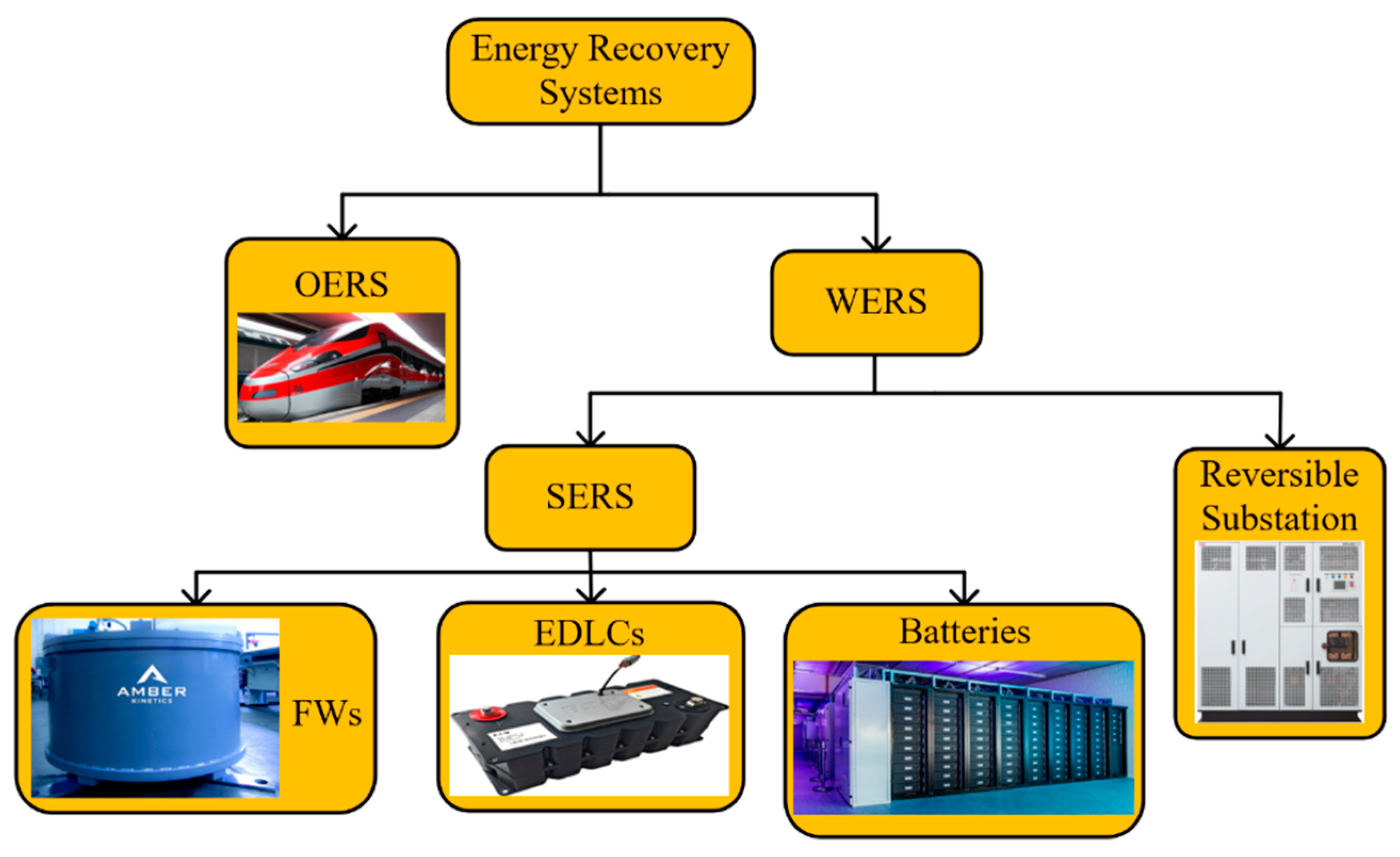
2. Energy Recovery Systems for Train Regenerative Braking

With reference to the recovery of the kinetic energy resulting from the braking transient of a railway trainsets, various approaches are being investigated in the literature [7,8,9,10], and one aspect that particularly draws the attention of many researchers concerns how to arrange a suitable energy recovery system (ERS) [11,12,13,14,15,16,17,18,19,20,21,22,23,24,25,26,27,28,29,30,31,32,33,34,35,36]. To-date the proposed technical solutions include on-board ERS (i.e., OERS) and wayside ERS (i.e., WERS). In the case of OERS the energy storage system devoted to recover the kinetic energy due to braking is installed on board the train, with clear advantages resulting from the possibility of immediately reusing the recovered energy for the supply of the trainset propulsion system and the consequent improvement in terms of energy saving for a given transportation service. However, the use of OERS with a large-enough capacity inevitably causes an increase in both volume and weight of the railway vehicle and, therefore, the overall energy consumption might be increased, as well as additional space on-board is required. On the other hand, WERS arrangements do not have an impact on the vehicle weight and volume, but require suitable electrical infrastructures being built along the railway route, such as either stationary energy recovery system (SERS) or reversible railway substations, as summarised in Figure 1.
A straightforward solution to recover the braking energy of trains would be accomplished by means of the use of reversible railways substations. Unlike the use of SERSs, this solution does not require setting-up an energy storage system as the power released by the trainset during a braking transient is directly fed back into a medium voltage AC distribution grid. However, due to the impulsive nature of the braking transient, the direct recovery of the braking energy into the medium voltage grid might not be acceptable to the distribution system operator (DSO) and, therefore, also this solution would require that a short-term energy storage system is accomplished in the reversible rail substation to smooth the power flow transient. The SERS-type solutions are the ones mostly considered to solve the braking energy recovery matter, and to this purpose the use of electrostatic double-layer capacitors (EDLCs) has been widely investigated [13,14,15,16,17,18,19,20,21,22,23,24,25,26,27] with the aim to increase the energy efficiency, voltage stability or both. EDLCs are characterised by high power density, high number of charging\discharging cycles (i.e., 200,000) and high round-trip efficiency. However, this solution results in high investment costs and low energy density. Another solution that is often being considered is based on the use of flywheels (FWs), that are capable of providing a lifetime of around 20 years and a round-trip efficiency in the range from 90% to 95%. Compared to EDLCs, the FWs show a higher energy density and much higher number of charging/discharging cycles (i.e., higher than 1,000,000), but they do have a significantly reduced power density and a need for frequent maintenance. A more cost-effective solution for recovering the train braking energy through a SERS-type arrangement is the one that relies on electrochemical cell batteries, particularly those ones based on lithium-ion technology [29,30,31,32], as this solution is recognised to have a higher value of energy density and lower payback time, if compared with both EDLCs and FWs. Therefore, in consideration of such favourable characteristics the study described in this paper has been developed with a SERS arrangement that combines together the distributed energy storage made available by the batteries of an EV fleet parked nearby the railways station, and a centralised energy storage that could be set up by means of the so-called second-life EV batteries. In the micro-grid under consideration, a suitable DC-DC converter is used together with the centralised energy storage for providing the voltage regulation of the micro-grid DC common bus-bar during the energy recovery transients, as discussed later on in this paper. The sizing of such a centralised energy storage is behind the scope of this paper, as it would require further evaluation of the overall DC micro-grid behaviour in terms of power flows due to the daily management of the EV fleet and the daily diagram of the input power resulting from the PV, i.e., photovoltaic, generating system, if actually installed on site. In the following, it is shown that at a railway station which has significant incoming and outgoing train traffic, e.g., resulting from an intense regional transportation service, the recovery of the energy from the braking transient of incoming trainsets yields the saving of a significant amount of energy that otherwise would be wasted by means of the rheostats that are currently used on board the trainsets. Such a valuable amount of energy is likely to be used for providing a supply of any electrical load within the railways system, but the proposed T2V mode of operation allows taking advantage of the battery storage being placed on board the EVs parked nearby the railway station.

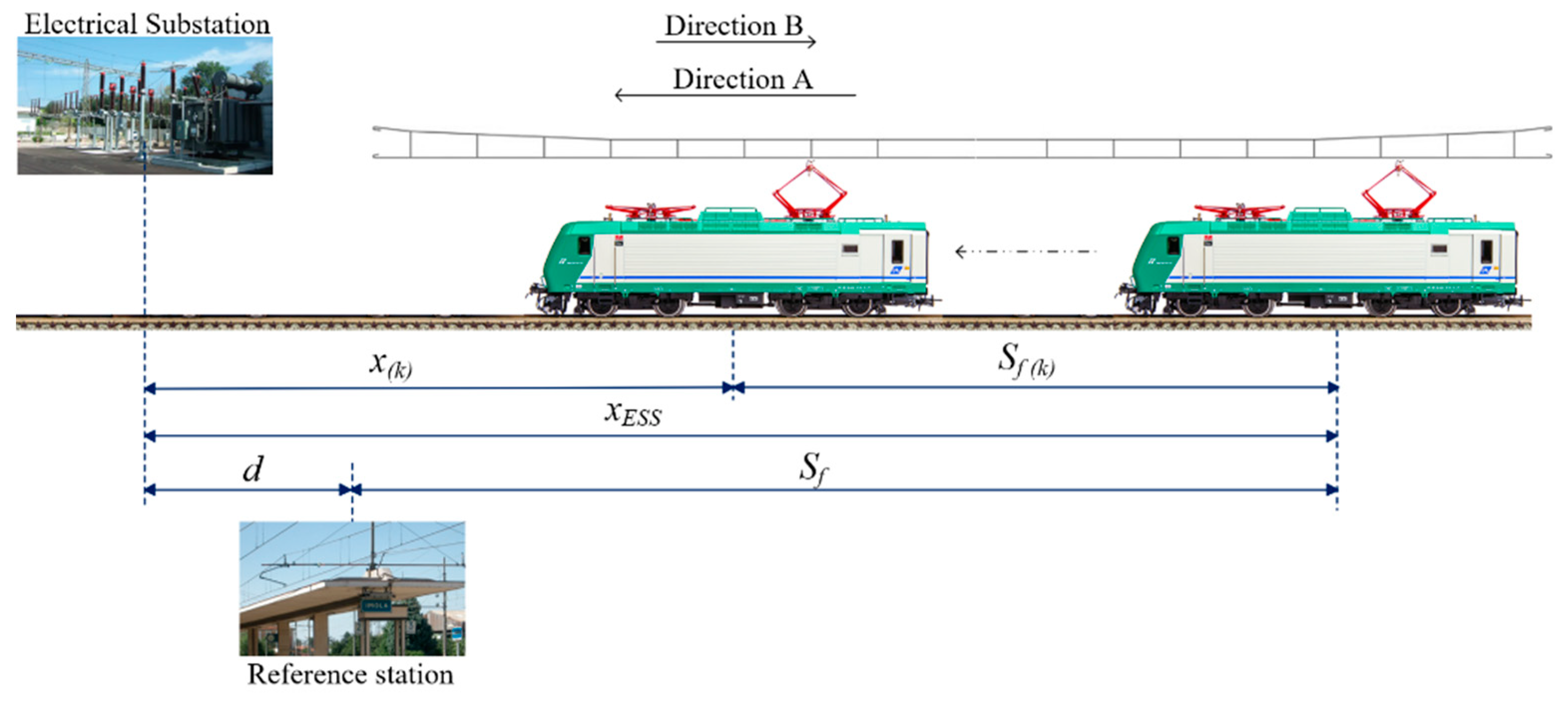
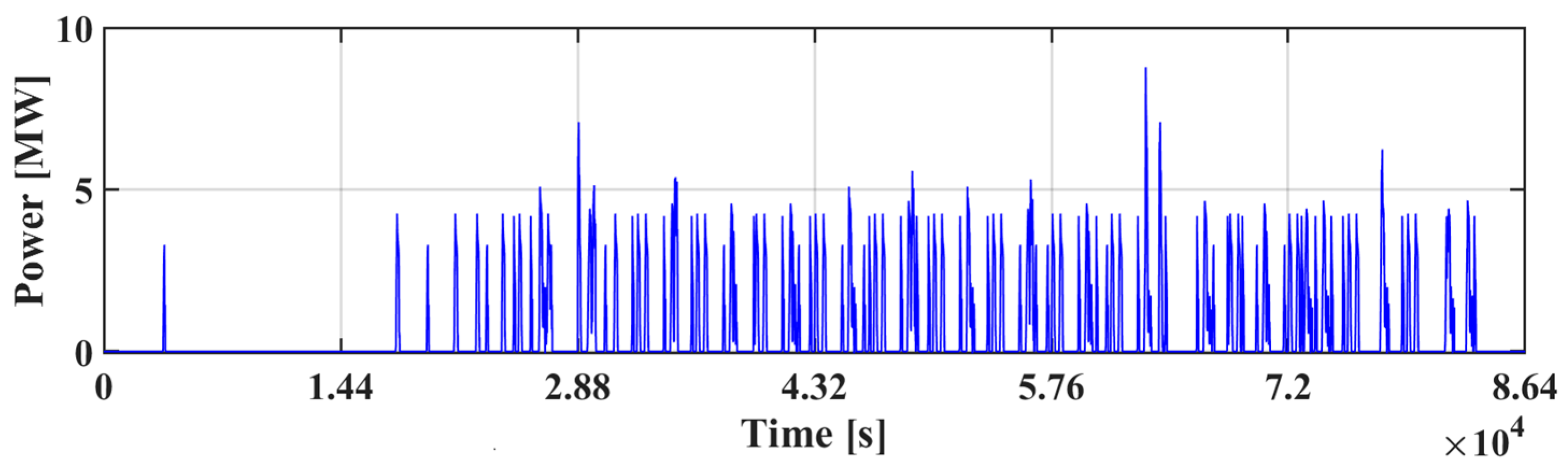
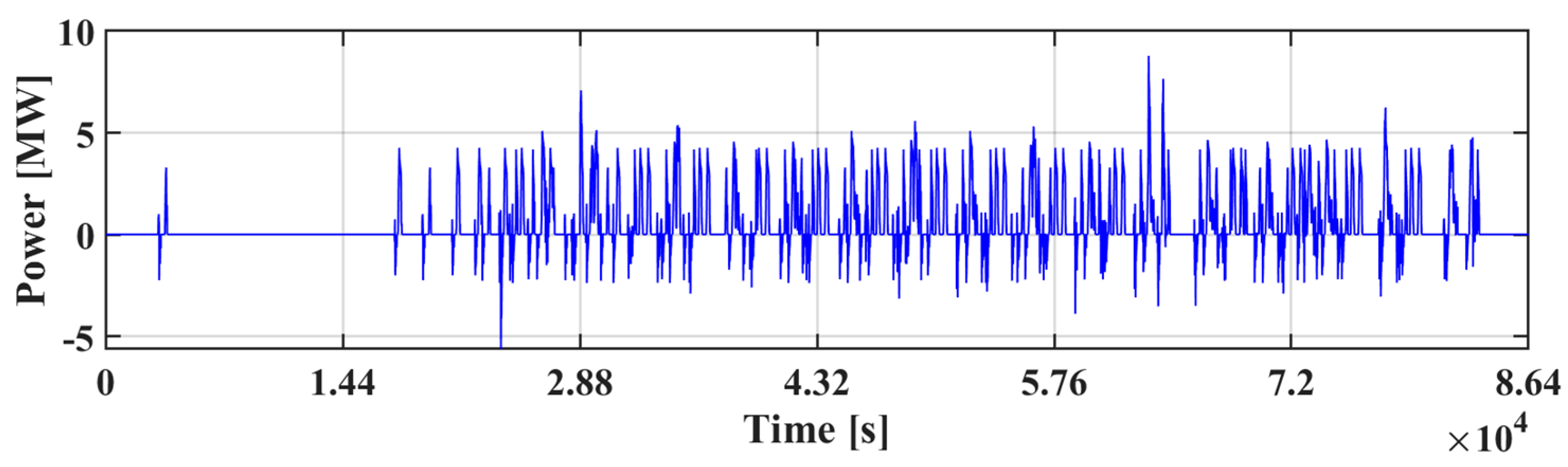
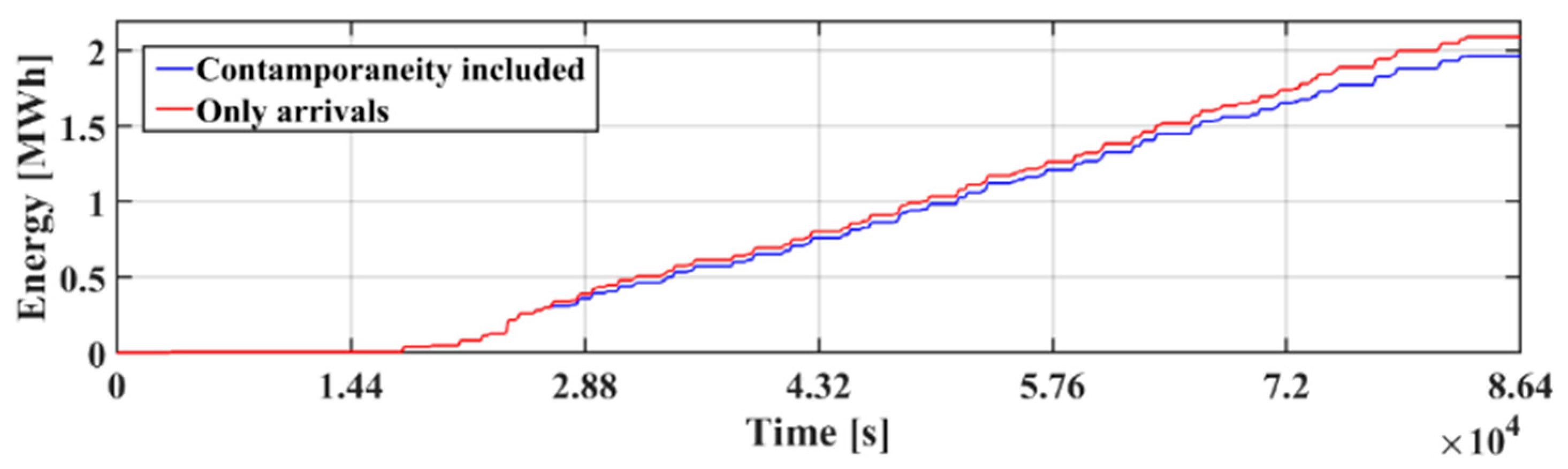
3. Estimating the Energy Recovery from the Timetable of a Railway Station

To the purpose of estimating the energy amount that is likely to be recovered from the daily traffic of trains at a given reference station of the railway system, a suitable methodology has been developed, as described in the following and schematically summarised in Figure 2. The first step of the proposed approach relies on considering the daily timetable that is being associated to a given railway station. Therefore, the number of both arriving and departing trains for train traffic along 24 h is known, and the departure or arrival time of each train is also known. Then, the motion behaviour of each train that is either leaving or arriving at the reference railway station can be modelled by means of an appropriate set of equations that describe the kinematic behaviour of the railway vehicle in the railway section which is travelled during the braking or acceleration transient. Further to that, according to the motion of each train, the electrical energy either required during the train accelerating transient or released by the train during the regenerative braking is likely to be calculated by means of a suitable electrical model that puts together both the modelling of the main components of the train propulsion system and the traction circuit from the train pantograph to the terminals of the railway substation. Starting from the timetable of the reference station, and considering the electrical power flow resulting in the traction circuit due to the motion of each train either arriving at or departing from the reference station, it is possible to evaluate the time behaviour of the electrical power that each train either requires from or makes available to the terminals of the railway substation, that is located near the reference station to supply the railway traction circuit. Hence, considering all the departing trains in a 24-h period, it is possible to determine the time behaviour of the electrical power supplied by the substation during the acceleration transients of these trains. On the other hand, considering all the trains arriving at the station according to daily train traffic, it is possible to determine the time behaviour of the electrical power that could be made available to the substation terminals for recovering energy. Therefore, by superimposing the daily trend of the electrical power required by departing trains with the one of the electrical power that arriving trains could make available through their regenerative braking, it is possible to finally determine the actual amount of electrical energy that can be recovered from the traction circuit over each single day of train traffic. This methodology, which considers the degree of contemporaneity between arriving and departing trains as a key variable in the estimation of the actual amount of recoverable energy, is further explained and validated in [6].
In the following, the overall model that has been implemented in the Matlab/Simulink environment for representing the kinetic behaviour of either arriving or departing trains, as well as an electrical system including both the railway traction circuit and the propulsion system of passenger trains mainly used for regional commuting service, is described. The same kinematic model is actually used for representing the motion of both the arriving and departing trains, but a difference was introduced in modelling the traction circuit that is associated with the trains arriving at the station and those departing from it. In fact, the arriving trains have been assumed to be fed through a cantilever power supply from the railway substation located nearby the reference station, whereas a bilateral power supply has been considered for the accelerating transient of departing trains. Such a different modelling of the train power supply is due to substantial difference between the time duration of the braking transient and that one of the acceleration transient. In fact, the accelerating transient of departing trains occurs along a railway track length which is significantly greater than the stretch of railroad track that is being travelled during the braking transient of a train arriving at the station. Thereby, for the trains leaving the reference station it is deemed to be reasonable to consider that during the long and smooth acceleration transient, the required supply is provided by both the two electrical substations (ESSs) located at either end of the railway section travelled by the train.

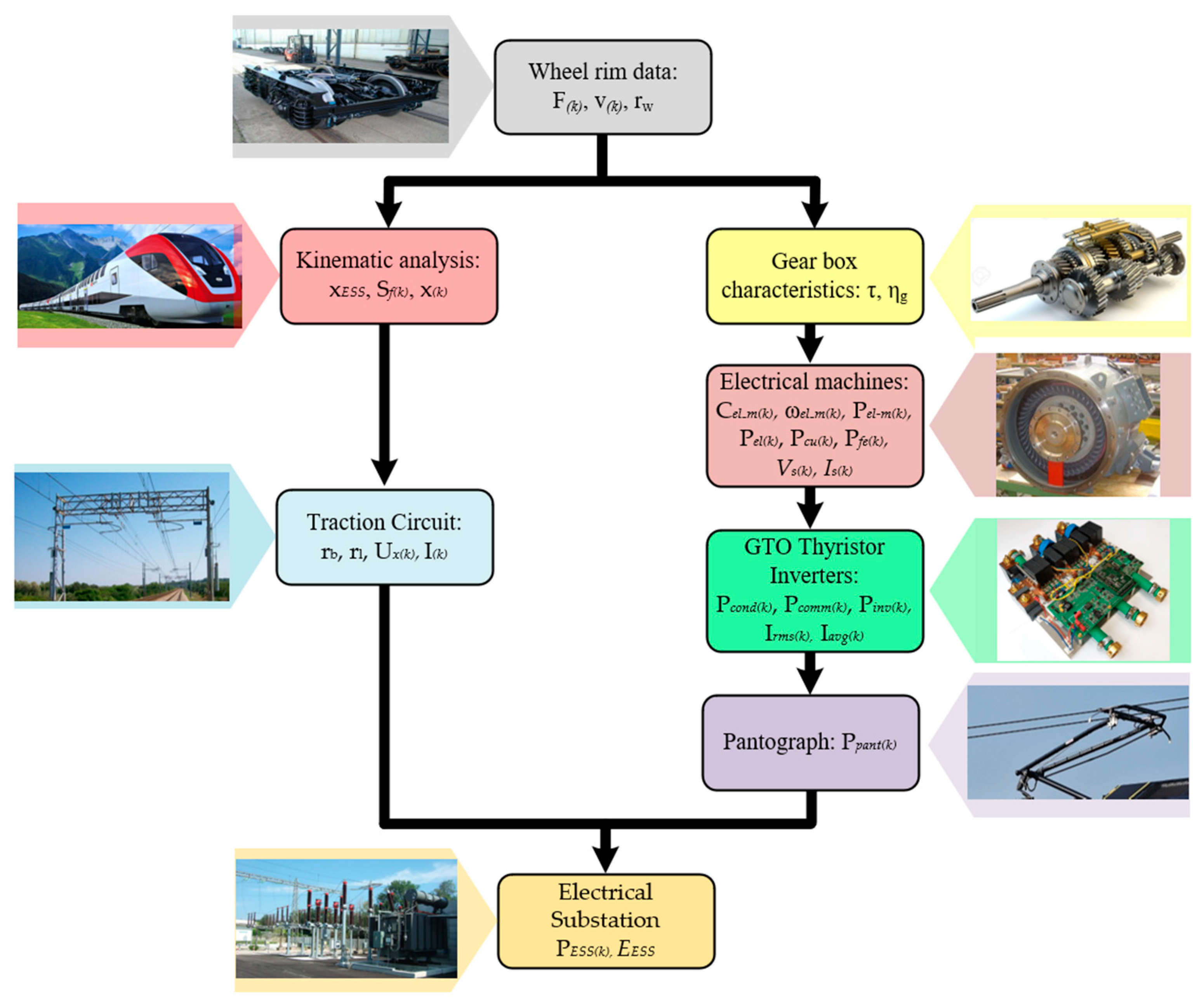
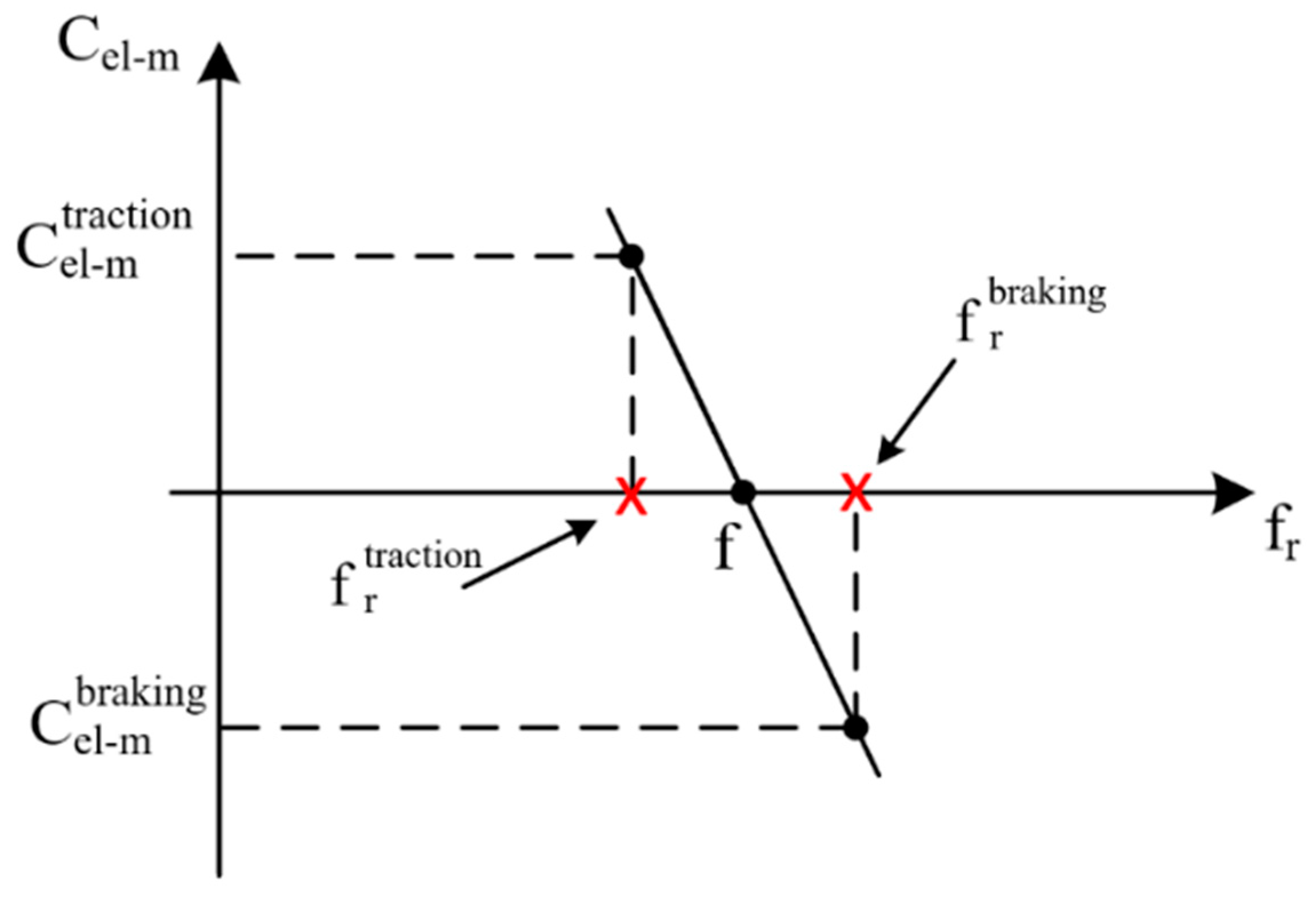
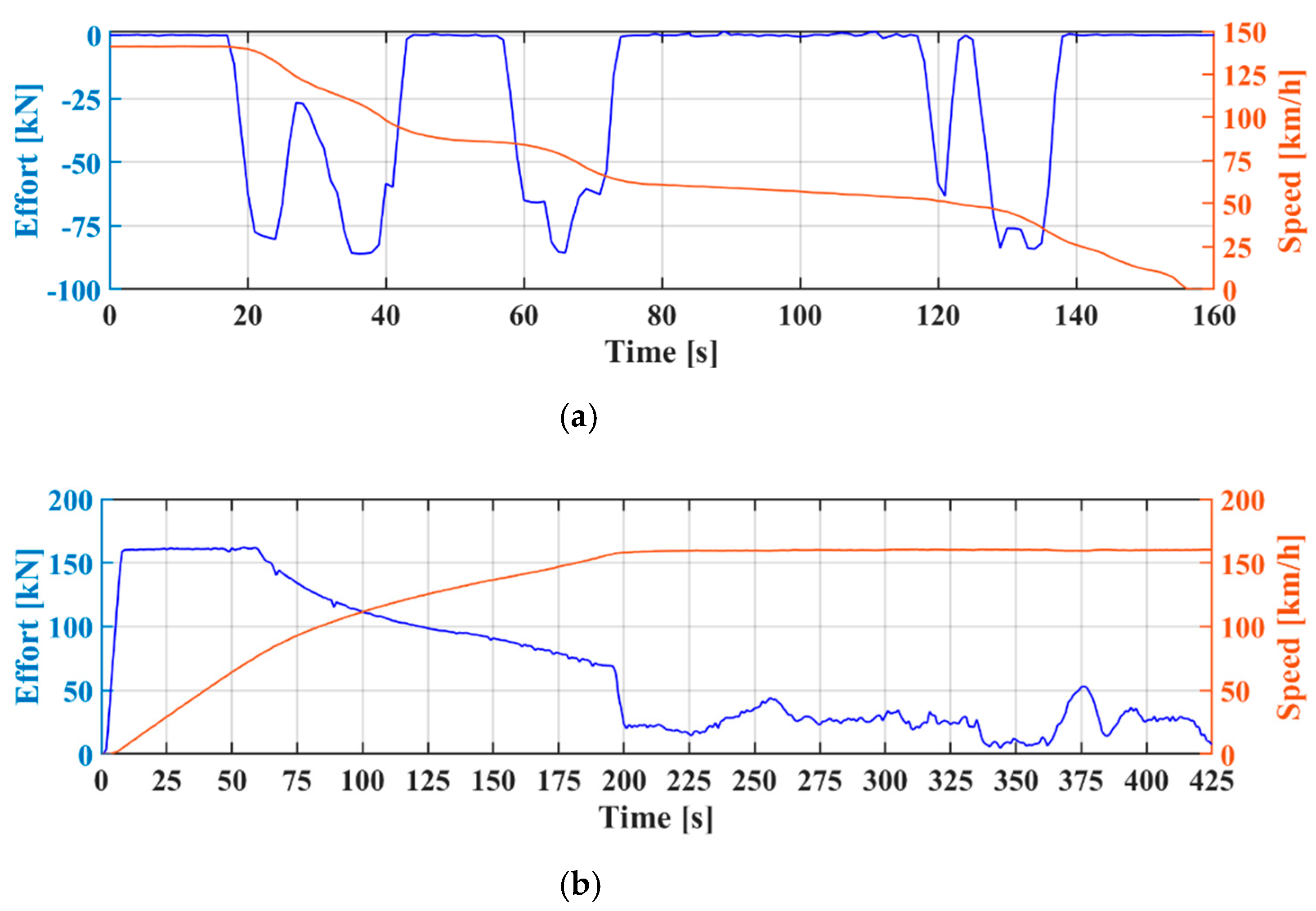
Modelling the Braking Transient for Arriving Trains

The modelling of the traction drives and the railway section has been carried out in order to estimate the recoverable energy over a single day of train traffic. Figure 3 represents, schematically, the railway section, including the station and the nearby ESS that supplies the traction circuit of this section. As shown in Figure 3, the ESS is located at a given distance d from the station, where the trainsets either conclude their braking transient or initiate their accelerating transient. Concerning the kinematic transients of trains either arriving to or departing from the station, the experimental campaign carried out with suitable sensors being placed on board the trains has made recordings available, over time, of the values of both the locomotive’s hook traction force and of the trainset motion speed.
Then, based on such experimental results, a quasi-stationary model has been built up within the Matlab/Simulink environment by considering that, in a prefixed time sampling step t(k), the values of the traction force F(k) and of the train speed v(k) are known and can be considered as constant if the time step is small enough compared to the mechanical time constant that regulates the speed variations in the train motion.
From these quantities, by means of an appropriate kinematic model that is representative of the train’s motion, the space covered by the trainset is calculated and, therefore, the instantaneous value x(k) of the train position with respect to the ESS is determined.
This value x(k) of the train position is then used to calculate the overall resistance of the traction DC circuit between the train pantograph and the ESS terminals. As an example, the procedure described above is schematically represented in Figure 3 for the case of a train braking transient. Starting from the available experimental data, it is possible to establish the space Sf that is covered by the train along the entire braking transient and, thereby, the position of the train with respect to the ESS (i.e., xESS = Sf + d) at the instant in which the braking transient begins.
Hence, at each time step (i.e., every 1 s, as assumed in this study) the space Sf(k) being covered by the train is calculated and the train position x(k) at the end of a given time step is determined, then becoming the value of the initial position of the train for the calculations carried out in the following time step. Obviously, an analogous procedure is implemented in case of an accelerating transient of trains departing from the station in order to calculate, at each time step, the resistance of the DC traction circuit, according to the train position with respect to the ESS. In parallel with modelling the kinetic transient of a given trainset either arriving at or departing from the reference station, the mechanical quantities available from the experimental campaign are used also for achieving the evolution over the time of both current and power at the DC terminals of the ESS. Hence, a quasi-stationary model is being actually implemented in the Matlab/Simulink environment with an overall algorithm that can be schematically depicted as shown in Figure 4.
For determining the time evolution of the electric power flow in the traction catenary during a given train’s motion transient, the electrical model is finalised to finding out, at each time sampling step, the actual value of both the voltage at the train pantograph and the current in the traction circuit. As schematically depicted in Figure 5, the electrical model used in this study has been developed to combine together the main components of a locomotive propulsion drive and the traction circuit between the ESS terminals and the train pantograph.
It is worth recalling that, to the purpose of this study, the operation of the various electrical components occurs by varying their own point of operation from one steady-state condition to another and, therefore, it is assumed that the transients in the electrical components are negligible as they are governed by much smaller time constants than the time constant related to the train motion transients. Hence, only the steady-state fundamental component of the electrical quantities is taken into account for the traction motors, the inverters and the DC circuit related to the train supply from the ESS.
As a result, each traction motor can be suitably represented by means of the classical equivalent circuit, usually considered for the analysis of the steady-state operation of an asynchronous machine, assuming that all the circuit parameters are already known from the results of tests carried out on the related machine. Further to that, each inverter can be modelled by means of the relationship between the rms value of the inverter line-to-line output voltage and the DC link input voltage, as well as by considering the overall power loss that occurs in each one of the inverter power electronic devices due to the current conduction and to the switching at a given switching frequency.
To this goal, data concerning both the Gate Turn Offs (GTOs) and diodes used in the traction inverters are taken from the manufacturer’s datasheet.
Starting from given values of the traction force F(k) and of the train speed v(k), at each time sampling it is straightforward to calculate the value of both the electromagnetic torque Cel-m(k) and the angular speed ωel-m(k) at the shaft of each electrical machine, as shown in Equation (1). To this goal it is assumed that all the Nm twin asynchronous machines provide an identical contribution to either the traction effort or the braking action, and the characteristics of the mechanical transmission system, such as the wheel radius rw and the gear ratio τ, as well as the efficiency ηg of the mechanical gear being interposed between the traction motor and the wheel axle, are known. Of course, the efficiency of the gear appears at the numerator or denominator of the torque expression given in Equation (1) depending on whether the train motion relates to either a braking or traction operating condition. From the relationships shown in Equation (1), the mechanical power Pel-m(k) at the shaft of each electrical machine can be calculated. Further to that, the machine rotor speed ωel-m(k) can be associated to a rotor electrical frequency fr(k), as written in Equation (2), that is inherently related to the rotor motion, where p is the machine pair of poles.
{ C e l m ( k ) b r a k i n g = η g e a r F ( k ) r w N m τ C e l m ( k ) t r a c t i o n = F ( k ) r w N m τ η g e a r ω e l m ( k ) = τ v ( k ) r w
Then, it is observed that within the torque range in which an asynchronous machine is usually operated, the mechanical characteristic, in terms of electromagnetic torque vs. rotor electrical frequency, is substantially linear, as shown in Figure 6. Hence, it can be considered that for any given value of the machine supply frequency f(k), the developed electromagnetic torque is directly proportional to the value of the so-called slip frequency fsl which is defined by the expression:
f r ( k ) = p ω e l m ( k ) 2 π
f s l ( k ) = f ( k ) p ω e l m ( k ) 2 π = f ( k ) f r ( k )
Therefore, from the torque value Cel-m(k) resulting from Equation (1), the value of the rotor slip frequency fsl(k) is determined and, thereby, the actual value f(k) of the machine supply frequency can be calculated such as:
f ( k ) = p ω e l m ( k ) 2 π + C e l m ( k ) k C
In Equation (4), the coefficient kC is a machine constant which is inherent to the particular machine design and it can be determined on the basis of the torque value that the machine makes available at its own rating value of mechanical speed.
Once the machine supply frequency has been determined, the steady-state equivalent circuit, shown in Figure 7, can be used at any given time sampling step to calculate the value of all the electrical quantities relevant to describe the steady-state operation of each traction machine. In particular, from the mechanical power Pel-m(k) the value of the power loss Pcu,r(k) in the rotor winding can be determined such as:
P c u , r ( k ) = f s l ( k ) f ( k ) f s l ( k ) P e l m ( k )
Hence, the rms value of the machine rotor current is given by:
I r ( k ) = P c u , r ( k ) 3 R r
From Equation (6), it is straightforward to calculate all the other relevant quantities, such as the ElectroMagnetic Force (EMF) induced by the airgap flux, i.e., Eag(k), the power loss in the iron of the machine stator, i.e., Pfe(k), the rms current Is(k) in the stator winding, and the related Joule power loss, i.e., Pcu,s(k). Finally, the electrical power Pel(k) required by all the asynchronous machines can be determined together with the rms value of the phase voltage Us(k) supplied by the inverter and the lagging angle φ(k) of the phase current, with respect to the phase voltage.
In order to achieve the voltage Ux(k) and current I(k) at the train’s pantograph, the model further considers the relationship between the AC phase voltage Us(k) supplied by the inverter and the DC voltage Udc(k) at the inverter input terminals, as given in Equation (7), where M(k) is the modulation depth.
M ( k ) = 2 2 U s ( k ) U d c ( k )
In addition to Equation (7), the electrical power at the inverter input terminals is considered in order to determine the current in the DC link of the overall traction drive. To this goal, the overall power loss in the power electronic conversion system is determined by using the approach earlier proposed in [37] and already used in [38]. Hence, both the switching power loss and the conduction power loss in the inverter switches and diodes are evaluated by considering only the fundamental harmonic of the inverter output phase current that is being represented by the time function:
i s ( k ) ( t ) = 2 I s ( k ) sin [ 2 π f ( k ) t ϕ ( k ) ]
Assuming that the sine-wave PWM technique is used to regulate the inverter output, under a constant fundamental frequency condition, the duty cycles of the top and bottom switches can be written, respectively, as:
{ d t o p ( k ) ( t ) = 1 2 [ 1 M ( k ) sin ( 2 π f ( k ) t ) ] d b o t ( k ) ( t ) = 1 2 [ 1 + M ( k ) sin ( 2 π f ( k ) t ) ]
Therefore, both the rms value and the average value of the current flowing in the switches (i.e., respectively, Isw,rms(k) and Isw,ave(k)) can be calculated as in the following:
{ I s w , r m s ( k ) = 2 I s ( k ) 1 8 M ( k ) cos ϕ ( k ) 3 π I s w , a v e ( k ) = 2 I s ( k ) ( 1 2 π M ( k ) cos ϕ ( k ) 8 )
On the other hand, the rms value and the average value of the current flowing in the freewheeling diodes (i.e., respectively, Id,rms(k) and Id,ave (k)) can be written as:
{ I d , r m s ( k ) = 2 I s ( k ) 1 8 + M ( k ) cos ϕ ( k ) 3 π I d , a v e ( k ) = 2 I s ( k ) ( 1 2 π + M ( k ) cos ϕ ( k ) 8 )
According to [39], in a three-phase inverter with sinewave PWM, the switching operation determines, in each switch, an average energy loss Eavg that can be considered to be nearly a linear function of the rms value of the current flowing in the device and, thereby, it can be written as:
E a v g = ( k o n + k o f f ) I s w , r m s ( k ) = ( k o n + k o f f ) 2 I s ( k ) 1 8 M ( k ) cos ϕ ( k ) 3 π
where kon and koff are coefficients being found from linearising the curves available in the manufacturer’s datasheet to represent the energy loss due to the typical turn-on and turn-off transients with given values of the junction temperature and of the operating DC-link voltage. Similarly, the switching operation determines, in each freewheeling diode, an average energy loss Err that can be considered to be proportional to the rms value of the operating current and, therefore, the curves available in the manufacturer’s datasheet can be linearised to find out the angular coefficient krr that characterises the specific linear function approximation. Hence, the energy loss in the inverter diodes can be written as:
E r r = k r r · I d , r m s ( k ) = k r r 2 I s ( k ) 1 8 + M ( k ) cos ϕ ( k ) 3 π
Then, the overall power loss in the inverter switches and diodes due to commutations with the switching frequency fsw can be calculated as shown in Equation (14), where Nsw is the number of switches and Nd is the number of diodes.
P l o s s , c o m m = ( N d E r r + N s w E a v g ) f s w
In addition to the commutation power loss, the conduction power loss resulting from the current flowing in either the inverter switches or diodes has to be considered. To this purpose it is recognised that the power loss due to conduction in the inverter switches can be expressed as:
P c o n d , s w = N s w ( V s w , o I s w , a v g ( k ) + r s w I s w , r m s ( k ) 2 )
with the value of the forward voltage Vsw,o and of the on-state resistance rsw that are taken from the manufacturer’s datasheet. Further to that, the conduction power loss in the diodes can be calculated as:
P c o n d , d = N d ( V d , o I d , a v g ( k ) + r d I d , r m s ( k ) 2 )
where Vd,o and rd are, respectively, the value of the forward voltage and the value of the on-state resistance that can be found in the manufacturer’s datasheet.
By taking into account the overall set of equations from Equation (7) to Equation (16), it is recognised that the overall power loss occurring in the switches and diodes of the entire power electronic conversion system can be expressed as a function of the voltage Udc(k) at the DC input terminals of each inverter and, consequently, of the voltage Ux(k) at the train’s pantograph which is twice the inverter DC input voltage.
Therefore, by means of suitable math elaborations, the electrical power Ppant(k) at the train’s pantograph can be written as:
P p a n t ( k ) = U x ( k ) I ( k ) = P e l ( k ) + P c o n d ( k ) ( U x ( k ) ) + P c o m m ( k ) ( U x ( k ) )
In addition to Equation (17), the unknown values of voltage Ux(k) and current I(k) at the train’s pantograph must satisfy the voltage equation of the traction circuit whose overall electrical resistance can be calculated based on the instantaneous position x(k) of the train, as determined using the kinematic model discussed above. To this purpose it is assumed that the braking transients of the trainsets occur in a section of the railway line that is supplied only by the ESS near the station where the train stops, and that the supply voltage UESS provided by such an ESS is being kept constant and regulated at the upper limit of the voltage nominal range, i.e., 3600 V. Hence, the electrical model is completed with the following equation of the traction circuit:
U x , ( k ) = U E S S ( r b + r l ) x ( k ) I ( k )
where the values per unit length of the electrical resistance of the contact line, i.e., rl, and of the track, rb, are assumed to be 34 mΩ/km and 18 mΩ/km, respectively. Therefore, the voltage at the train’s pantograph Ux(k) and the current I(k) in the traction circuit can be calculated by solving, together, Equations (17) and (18). Clearly, the current I(k) would be either absorbed or released at the train’s pantograph depending on whether a traction or braking operation is occurring in the trainset motion.
The model discussed above, therefore, allows, as the force exerted on the locomotive hook and the speed of the train vary, one to determine the time behaviour of the current at the DC terminals of the ESS. This result has a twofold significance, as further discussed in the following of this paper. On one hand, once the time behaviour of the current I(k) has been determined, it is straightforward to calculate the power PESS(k) = UESS·I(k) at the DC terminals of the ESS and then, by integrating this power over the time, the recoverable amount of energy resulting from the braking transient of an arriving train can be finally estimated. On the other hand, the knowledge of the time behaviour of the current in the catenary as a result of the braking transient of a train allows for investigating the dynamics of the envisaged DC voltage micro-grid that includes a suitable SERS arrangement. Particularly, it allows for evaluating the time response of the control system used in the DC-DC converter that is operated to recover the braking energy from the catenary into the micro-grid. Further to that, it allows for the suitable tuning of the control system that, by means of the DC-DC converter being used to connect the SERS to the micro-grid common bus-bar, acts to provide suitable stability of the micro-grid DC voltage.

4. Case of Study: Imola Railway Station

The study discussed in this paper has been developed by considering the railway traffic in the station of the Italian city named Imola, which is characterised by a significant number of both incoming and outcoming regional trainsets due to daily services for commuting passengers. The railway operator provides this service with passenger trains usually pulled by locomotives of type E.464, whose main characteristics are summarised in Table 1.
The propulsion system of the E.464 locomotives relies on four asynchronous motors, each one having dual-star three-phase stator winding, a cage-type rotor, and the rated power of 893 kW. The traction drive of the electronics is accomplished by means of two three-phase GTO inverters, each one having a 1900 kW rated power. For all the four traction motors, each one of the GTO inverters supplies one of the two star-connected three-phase winding, and provides a suitable control of the motor’s supply voltage amplitude and frequency. The E.464 locomotives have the capability of providing electrical braking by means of two braking rheostats, each one being fed from the inverter DC link through a DC-DC GTO chopper that allows for the suitable regulation of the braking DC current.
The study, herewith discussed in the following, is based on the experimental data that became available as a follow up of an extensive recording campaign that the railway operator carried out on board the E.464 locomotives used in the railway section, in which the Imola station is included. Particularly, the study considers the experimental traces achieved from either braking or accelerating transients of trainsets either arriving or departing daily at the Imola train station to evaluate the overall amount of energy that is actually available to be recovered along a single day of traffic operation. Figure 8 gives examples of the recording traces that were acquired on board E.464 locomotives, in terms of both the effort at the wheel rim and train speed as functions of the recording time. A typical braking transient of a trainset arriving at the Imola station is reported in Figure 8a, whereas Figure 8b shows the accelerating transient of a train departing from the same station.
As already mentioned above, attention is given also to trains departing from the reference station as it was considered a mandatory constraint that the energy released by a trainset during its braking transient would be first made available to other trains that were accelerating on the same railway section, if any. Thereby, the study has been developed by considering all situations along a day of operation in which, on the basis of the station’s traffic timetable, the braking transient of an arriving train and the acceleration transient of a train leaving the Imola station occur simultaneously. Hence, whenever the arrival of a train and the departure of another train are simultaneous, it was considered that the energy released by the braking train is supplied to the accelerating trainset, and thereby is not available for being recovered and stored.
To the purpose of evaluating the recoverable energy over a single day of operation, the railway traffic, resulting from the station daily timetable, is taken into account in order to consider the braking transient of all the incoming trains that allow for the recovery of energy into the micro-grid. So, as already discussed in [6], the estimation of the actual amount of braking energy that can be recovered for the micro-grid has been carried out by considering the daily timetable of train traffic in the reference station, that combines 103 incoming trains and 105 outgoing trains, with a certain number of arrivals and departures that are scheduled to occur almost simultaneously.
In other words, the novel approach used in this study allows the estimation of the actual amount of recoverable braking energy that otherwise would have been simply converted to heat in the locomotives’ on-board rheostats as no other electrical load would be connected to the traction circuit at the time the braking transient occurs. It is also worth highlighting that the approach used in this study clearly puts into evidence that a valuable amount of energy is also saved in terms of energy supplied by the electrical substation (ESS), as if a braking transient and an acceleration transient occur simultaneously, the DC power requested by a departing train is either fully or partially compensated by the regenerative power flow that the braking transient of the arriving train makes available in the traction catenary.
For the kinetic transient of each of the trainsets either arriving to or departing from the reference station, the quasi-stationary model described in the previous section has been utilised in order to highlight the trend over time of the power flow at the DC terminals of the ESS to find out the amount of braking energy that can be actually recovered into the micro-grid. Then, according to the methodology discussed in Section 3, the ESS power profile related to the overall incoming railway traffic—i.e., a total of 103 trains each day—has been built up as shown in Figure 9.
As already mentioned, the time behaviour of the output power at the terminals of the ESS is achieved as shown in Figure 10 by considering the overall railway traffic of departing trains (i.e., a total of 105 departing trains each day). This result is needed in order to consider the contemporaneity between trains that operate with regenerative braking and those ones that, at the same time, are being operated under traction conditions due to their accelerating transient.
Finally, Figure 11 shows the trend over time of the power flow at the DC terminals of the ESS due to the railway traffic in the reference station according to a given daily timetable of arrivals and departures. Negative values of the DC power flow refer to operations with the recovery of braking energy into the DC micro-grid. To this goal, it is assumed that power resulting from a train braking transient is drawn from the railway catenary by means of a suitable DC-DC converter that is being connected in parallel to the terminals of the ESS, as discussed later in this paper.
Having determined the power flow at the DC terminals of the ESS due to the railway traffic in the reference station, the amount of energy that is recoverable from train braking transients can be calculated over a single day of operation.
Figure 12 shows the overall amount of energy (i.e., shown with a red trace) that would be recoverable from the braking transient of the trains arriving in the reference station according to the daily timetable of arrivals. Considering that some departures and arrivals occur almost simultaneously, and that in this specific situation the braking energy of an arriving train is made available for the acceleration transient of a departing train, the energy actually recoverable in the micro-grid on a single day of train traffic decreases slightly, as represented by the blue trace in Figure 12.
As shown, the amount of energy that is actually recoverable in the envisaged railway DC micro-grid is slightly less than 2 MWh per day, which is a quite significant amount if one considers that it would roughly correspond to the average energy consumption of a fleet of 100 EVs, having, for each vehicle, an expected autonomy of about 100 km for operation within the city traffic. Further to that, starting from results shown in Figure 11, the overall amount of energy required for traction by the ESS has been estimated to be about 15 MWh, as depicted in Figure 13. Hence, it is recognised that the net recoverable energy from the braking transient of arriving trains is about 12% of the overall energy required each day for traction operation.

5. Discussion of Results

As early shown in Figure 9, the ESS power flow due to the incoming railway traffic shows positive, negative, as well as null values, even if a braking transient occurs. In order to understand such behavior, the experimental traces shown in Figure 14 should be considered as it is found that the time variation of mechanical torque at the wheel rims during a train braking transient is strongly influenced by the style of driving executed by any specific train driver.
With reference to Figure 14, it should be noted that in the braking transient for approaching the stopping point in the station, the braking transients are performed in a different way depending on the driving style adopted by the driver and the railway track characteristics (i.e., altimetry, curves and so on). The reason is due to a non-standardised manoeuvre for the braking phase related to approaching the station area. In general terms, the various styles of driving have a significant impact on the value of the recoverable energy that can be achieved from the braking transient of each train, as shown in Figure 15.
Therefore, due to the random nature of the style of driving being utilised in the braking transient, the value of the recoverable energy is actually subject to a random behaviour. To the purpose of understanding how much the amount of recoverable energy is influenced by the style of driving, a suitable model has been implemented by considering a Monte Carlo procedure to randomly assign a specific driving style to each braking transient of trains arriving at the reference station. Hence, starting from the experimental data available for different trains arriving at the reference station, an algorithm has been set up to associate, by using a random way and depending on the travelling direction of the specific train, one of the available experimental traces of braking transient. Results achieved from this study are shown in Figure 16, and it is found that the value of recoverable energy in a single day of train operation should be expected to vary in the range from 2 MWh to 2.5 MWh. These results relate only to the incoming train traffic and, therefore, the contemporaneity between arriving and departing trains is not included. Nevertheless, based on results earlier shown in Figure 12, it is clear that, for the specific case of study under investigation, the contemporaneity between arriving and departing trains gives rise to a slight reduction of the recoverable energy value and, consequently, would not significantly change the results shown in Figure 16.

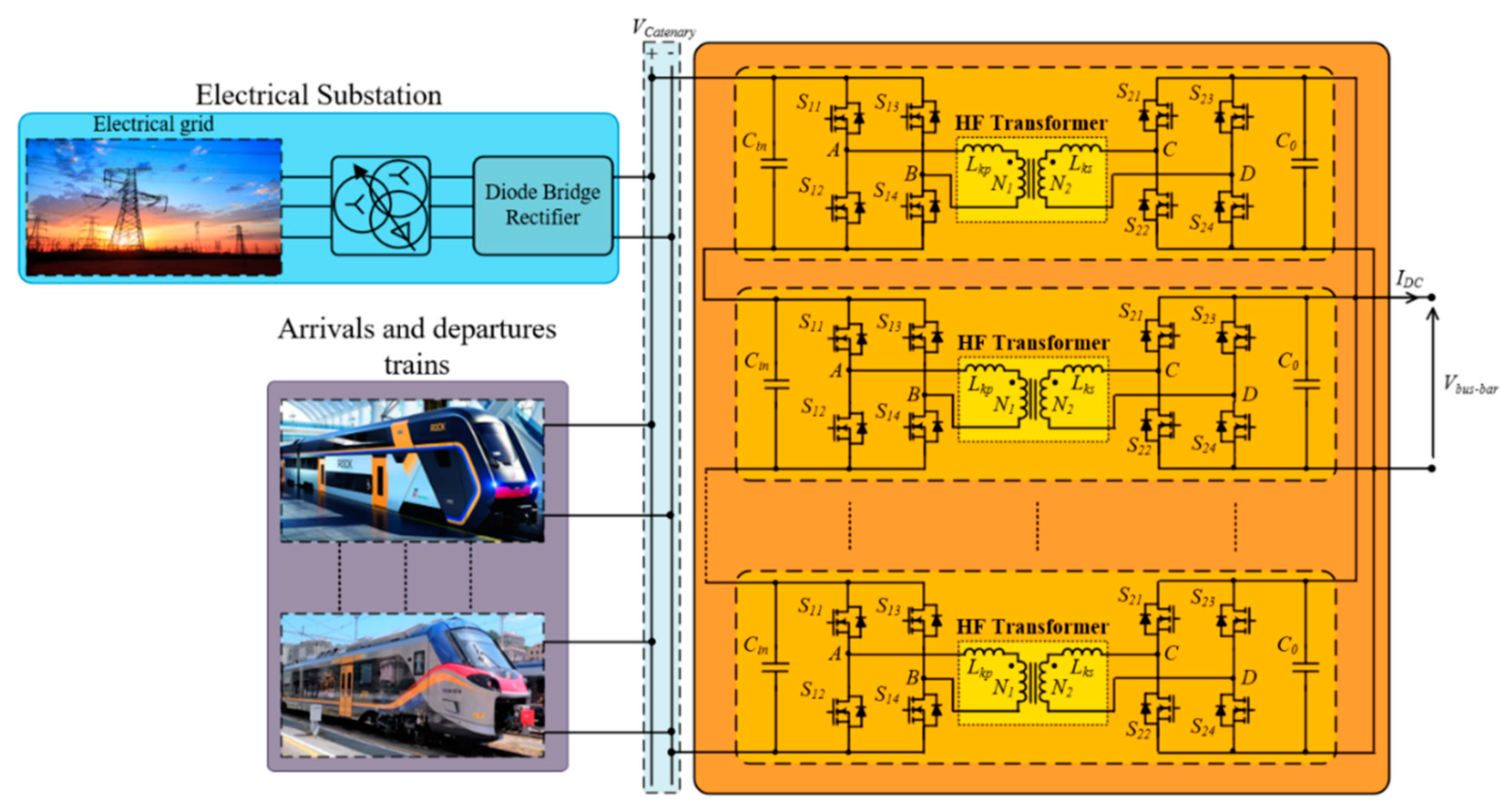
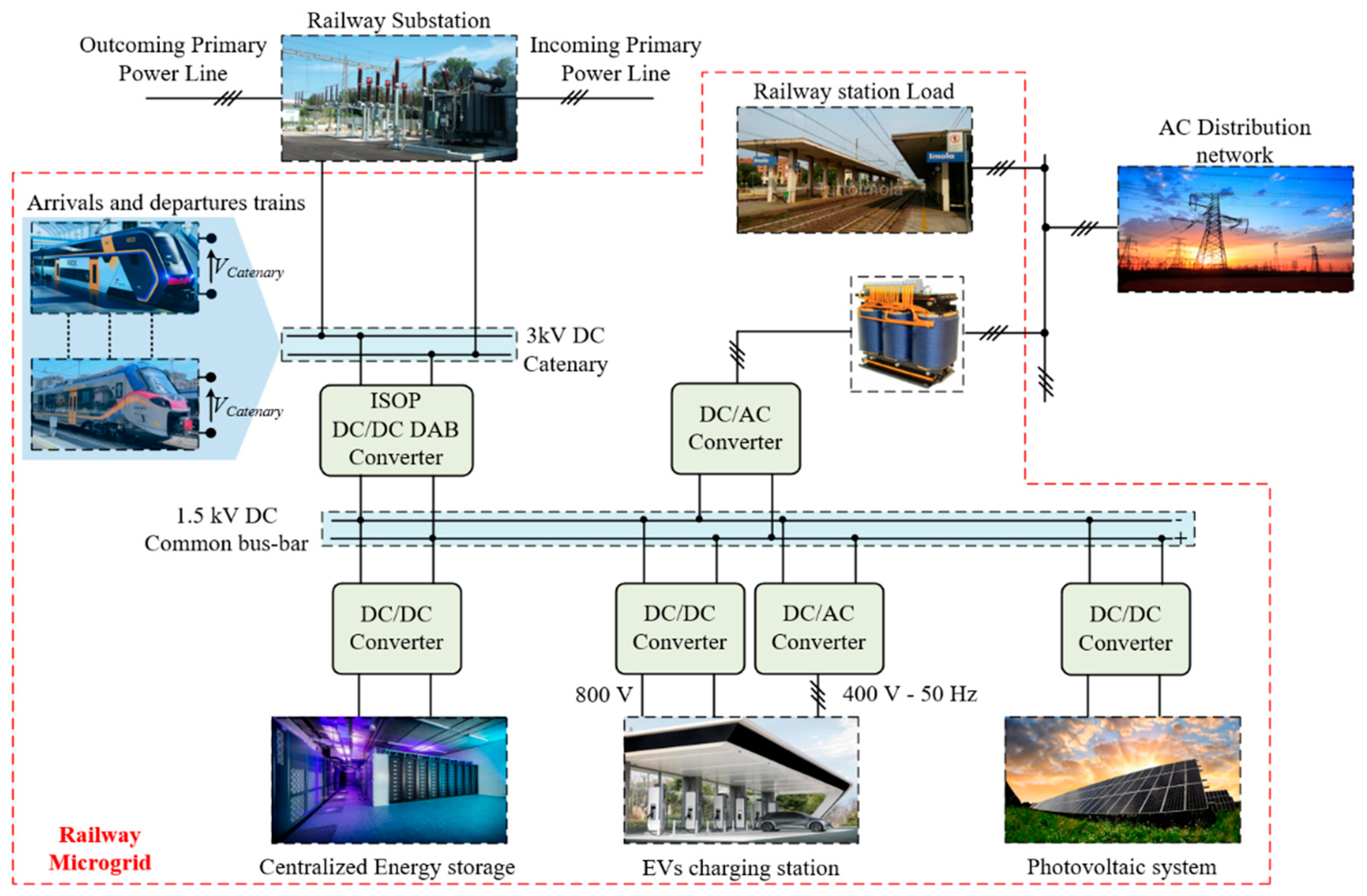
6. Architecture of the Railways DC Micro-Grid

According to the usual arrangement of a railway ESS, it is assumed that the traction circuit is being supplied by means of a three-phase diode bridge rectifier that is fed from the national electrical grid throughout a three-phase transformer having two secondary windings, one with a delta connection of the phases, the other with star-connected phases. To the purpose of recovering energy from the traction circuit, whenever the electrical power resulting from the braking transient of a train instantaneously exceeds the power requested by another trainset that is being eventually operated in the same section of the traction circuit, a suitable Dual-Active-Bridge (i.e., DAB) DC-DC power converter is connected to the traction catenary, as shown in Figure 17.
The envisaged DAB converter is arranged with a modular configuration, being often referred to as an ISOP (i.e., Input Series Output Parallel) configuration, and the output terminals of such a DC-DC converter provide voltage supply to a common bus-bar that is the backbone of the micro-grid to be kept operating at the nominal DC voltage of 1500V. The overall architecture of the envisaged railway’s DC micro-grid is schematically depicted in Figure 18. As mentioned earlier, it would include a PV generating system that would be connected to the micro-grid DC common bus-bar by means of a suitable DC-DC converter. This converter operates by having the maximum power transfer to supply the micro-grid loads, such as the railway station ancillary loads and the EVs charging infrastructure. The rating power of the PV generator is determined by the actual parking area available for hosting the EVs’ fleet near the railway station. The combination of the PV generating system and of the energy storage being available in the batteries of the parked EVs would be utilised for providing voltage and/or frequency regulation services to the DSO, particularly in the occurrence that most of the EVs are out of the parking area and the PV generated power exceeds the request of the railway station loads.
To this goal the micro-grid is equipped with a grid-tied three-phase inverter having the 5-level E-type inverter configuration that has been demonstrated to achieve both an efficiency higher than 98%, and a total harmonic distortion of the output’s current waveform lower than 2% when the converter is operated in a grid-tied operation mode [40]. The infrastructure dedicated to charging the EVs fleet is fed by means of a DC-DC multi-port DAB converter [39] that would be likely designed to provide 800 V DC rated voltage output in order to allow fast charging of future EVs. An additional DC-AC converter could also be provided in order to arrange for a three-phase AC supply at 400 V, 50 Hz.
Such centralised energy storage would be accomplished by means of assembling lithium-ion second-life batteries to get DC energy storage with an 800 V rating voltage. The capacity of such an electrochemical accumulator would be rather reduced as the use of such energy storage is aimed exclusively at the management of power transients in the micro-grid. To this goal, the centralised energy storage is connected to the DC common bus-bar by means of a DC-DC converter that dynamically operates to keep the DC common bus-bar at the rating voltage of 1500V. The voltage control implemented through the centralised storage system and its associated DC-DC converter is discussed later on in this paper. The connection between the micro-grid and the railway catenary is arranged by means of a modular DAB type DC/DC converter having an ISOP configuration, as earlier shown in Figure 17.
The proposed modular configuration allows for a converter operation with a high-power rating, but with relatively reduced voltage stress of both the active and passive power components of the converter. Further to that, the parallel configuration used for the converter modules at the output terminals allows for the converter design with the power semiconductors having relatively reduced the current rating. The modular configuration of the proposed DAB converter provides fault-tolerant features whenever the selected number of modules is high enough to get the required level of redundancy. As schematically shown in Figure 17, each DAB converter module consists of two H-bridge converters with a high-frequency transformer being interposed between them.
For the specific application being considered in this study it is envisaged that the DAB converter would be arranged with eight twin modules. The power rating of each module is determined by the voltage and current ratings of the power semiconductors. Assuming that the catenary is operated with a DC voltage up to 3600 V, in each module, the power semiconductors of the input H-bridge would be required to withstand a DC voltage of 450 V, whereas the power semiconductors of the output H-bridge have to be selected for operating with DC voltage of 1500 V. Consequently, the power semiconductors used in the input H-bridge of each converter module should have a rating voltage of 700 V, whereas the output H-bridge should be arranged with power semiconductors having a 1700 V rating voltage. Assuming that the envisaged DAB converter would be required to have a rating power of 2 MW to handle the power flow resulting from train braking transient, the input H-bridge of each module would be required to have power semiconductors with a rating current of about 600 A, whereas the output H-bridge would require power semiconductors with a rating current of about 200 A. Considering design requirements, such as high efficiency and high power density, power semiconductors based on the SiC technology should be considered. The high-frequency transformer of each converter module would be arranged with the so-called shell type configuration in order to achieve enough reduced value of the transformer leakage inductance, being this a design parameter of great influence for the DAB converter performance.

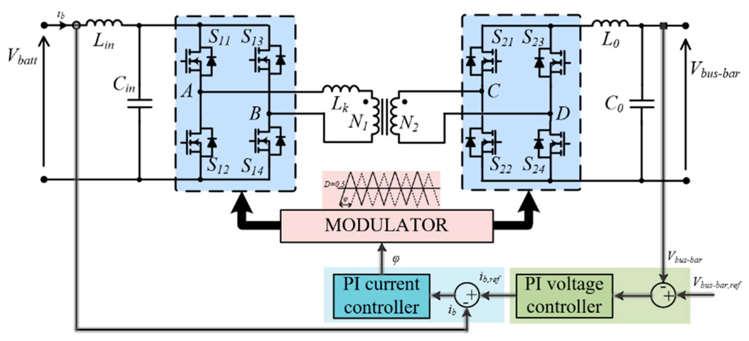
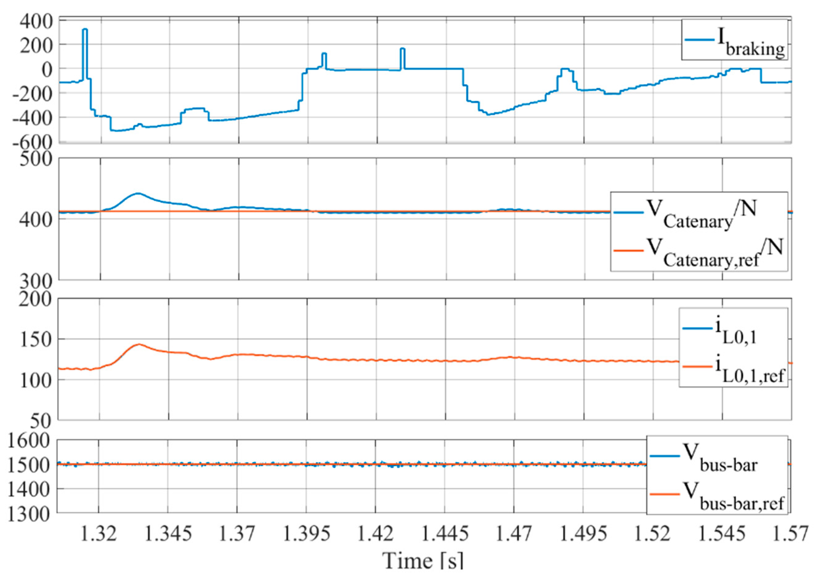
7. Dynamic Control of the Micro-Grid DC Voltage during Train Braking Transients

As already mentioned, the envisaged DAB converter would have eight twin modules that have input H-bridges connected in series among them, whereas the output H-bridges have output circuits being connected in parallel. The layout of each module of the proposed DAB converter is shown in Figure 19. In the input circuit of each DAB module, a suitable capacitor is placed to operate, charged at a voltage value that at any time equals the fraction of the catenary voltage value, determined by the number of modules being connected in series among them. On the other hand, the output circuit of each DAB module includes a suitable L-C filter to reduce the ripple of the output current. The average output current of each DAB module is the fraction of the DAB output current, determined by the number of modules being connected in parallel among them.
The power PDAB,N that is transferred from each DAB DC input terminal to the output terminal, connected to the micro-grid common bus-bar, is adjusted by controlling each phase angle φ1, φ2,..., φN, according to Equation (19), where n = N1/N2 is the transformer turns ratio, fsw is the switching frequency being used for the two H-bridges in each DAB module, and the parameter Lk = Lkp + n2Lks is the total leakage inductance on the transformer primary winding.
Whenever the DC power being injected in the traction catenary exceeds the power requested by the electrical loads connected to the catenary itself, the voltage at the terminals of the DAB converter input capacitors suddenly increases. Therefore, the DAB control system is arranged to control the DAB output current in order to keep at a given reference value the voltage at the terminals of the input capacitor.
P D A B , N = n V c a t e n a r y V b u s b a r 2 π f s w L k φ N ( 1 φ N π )   with   N = 1 , 2 , , 8
As shown in Figure 19, each DAB control system puts together a current controller, being used to regulate the output current iL0,1, iL0,2, , iL0,N, with a voltage controller that operates to keep at a given reference value Vc,ref = VCatenary/N the voltage at the terminals of the input capacitor.
The output of the PI voltage controller determines the reference current that is being used in the current control loop. The error in the current control loop (i.e., eN = i0,N,refiL0,N with N = 1, 2, …, 8) determines the phase-shift angle φ1, φ2,..., φN, between the carrier signals used in the modulation of the H-bridges connected, respectively, to the primary and secondary winding of the transformer. By comparing the duty cycle D = 0.5 with the phase-shifted carrier signals, the switching signals of the power semiconductors are generated in the H-bridges. While the modular DAB converter operates to transfer DC power from the traction catenary to the micro-grid common bus-bar, on the other hand another DC-DC DAB converter would be used together with the centralised energy storage to provide the suitable control of the micro-grid bus-bar voltage Vbus-bar at the desired value of 1500 V. As schematically shown in Figure 20, the control system devoted to regulating the voltage of the micro-grid bus-bar includes both a current control inner loop and a voltage control outer loop.
The voltage control loop determines the reference value of the current control loop by comparing the actual value of the micro-grid bus-bar voltage with respect to the desired reference value. Whenever the bus-bar voltage exceeds the reference value, a power flow from the micro-grid bus-bar to the centralised battery is commanded by means of an increase of the reference value of the battery charging current. Of course, whenever the bus-bar voltage goes below the reference value, the power flow in the DAB converter is reverted and the centralised energy storage is actually utilised to supply power to the micro-grid in order to keep the bus-bar voltage at its reference value. Based on the quasi-stationary model discussed earlier in this paper, the time behaviour of the current injected into the micro-grid bus-bar due to a train regenerative braking transient can be achieved. Figure 21 shows the trend over the time of the current Ibraking that would result at the terminals of the ESS due to the braking transient of a train arriving at the reference station.
As shown, the DC-DC converter of the centralised energy storage suitably regulates the common bus-bar voltage at the reference value of 1500 V, whereas a modular DAB converter connected to the railway traction circuit is capable of keeping the catenary voltage VCatenary at the reference value set forth at 3300 V. It is noted that the traces of the measured DAB single module output current iL0,1 and of the reference output current iL0,1,ref are perfectly overlapping with each other. Whenever the train starts a braking transient, the input voltage VCatenary/N of a single DAB module suddenly increases and, therefore, the single DAB converter output current iL0,1 increases in order to draw power from the railway catenary, thereby regulating the voltage VCatenary as requested.

8. Conclusions

The study presented in this paper concerned a railway DC micro-grid that would be suitably connected to the 3 kV DC catenary of the railway system in order to recover energy from the braking transient of trainsets arriving in a given railway station where a fleet of EVs is made available to train passengers in order to offer an integrated mobility service “Train plus EV”. Starting from the experimental data that became available as the follow up of an extensive recording campaign that the railway operator carried out on board regional service trains being operate with E.464 locomotives, the study has considered the experimental traces achieved from either braking or accelerating transients of trainsets either arriving or departing daily at a reference railway station, in order to evaluate the overall amount of energy that is actually available to be recovered along a single day of traffic operation. Hence, the first part of this paper has been dedicated to show that, at a given railway station where regional rail traffic is prevalent, the recovery of energy, resulting from the braking transients of arriving trains, can provide a valuable amount of energy that, on a daily basis, is high enough to supply the charging systems of a fleet of EVs. Therefore, the storage systems of the EVs being parked nearby the railway station are used as a WERS to accumulate the train braking energy, thus realising a T2V operating mode which makes it possible to make significant savings in the cost of the storage system needed to store the braking energy of trains.
Based on a detailed model that includes both the locomotive propulsion system and the DC traction circuit, the time behaviour of the power flow due to the train braking transient has been highlighted in order to understand the design requirements for the DC-DC power electronic converter being connected to the railway catenary to recover the braking energy into the railway DC micro-grid. With concerns to that, a modular DAB topology has been proposed and briefly discussed, as well as the overall architecture of the envisaged railway micro-grid having been described. In particular, it has been shown that the micro-grid includes a DC common bus-bar for feeding the electrical infrastructure devoted to charging a fleet of EVs, as well as to supply the railway station ancillary loads together with a PV generating system that could be arranged by using suitable PV canopies in the EV parking area. A centralised storage system is also connected to the micro-grid DC common bus-bar in order to dynamically compensate any sudden mismatch condition between the available input power and the power demand from the micro-grid electrical loads. Concerning that, the paper has demonstrated that, in the course of the power flow transient due to the braking of an incoming train, the DC voltage of the common bus-bar is suitably kept at its reference value by means of the control action carried out through a DC-DC power electronic converter that it is purposely used to connect the centralised energy storage to the common bus-bar of the micro-grid DC.
Further investigation on the subject matter of this paper is undergoing and will be dedicated to a deeper analysis of the power flows in the proposed railway micro-grid. This will consider the possibility that such a micro-grid is used also to provide the voltage and/or frequency regulation services to the DSO by means of a vehicle-to-grid approach that would benefit the valuable energy storage available from the fleet of EVs.

Author Contributions

Conceptualization, S.M., M.d.B. and F.C.; methodology, S.M., M.d.B. and D.M.; software, S.M. and M.d.B.; validation, S.M. and M.d.B.; formal analysis, S.M., M.d.B. and D.M.; investigation, S.M. and M.d.B.; resources, F.C.; data curation, S.M. and D.M.; writing—original draft preparation, S.M. and M.d.B.; writing—review and editing S.M., M.d.B. and F.C.; visualization, S.M., M.d.B. and F.C.; supervision, F.C.; project administration, F.C.; funding acquisition, F.C. All authors have read and agreed to the published version of the manuscript.

Funding

This research received no external funding.

Institutional Review Board Statement

Not applicable.

Informed Consent Statement

Not applicable.

Data Availability Statement

The study does not report any data.

Conflicts of Interest

The authors declare no conflict of interest.

Nomenclature

Cel-m(k)electromagnetic torque (Nm)I(k)current at the train’s pantograph (A)
ddistance from electrical substation and the station (m)Id,ave (k)average value of the diode current (A)
dbot(k)bottom switch’s duty cyclesId,rms(k)RMS value of the diode current (A)
dtop(k)top switch’s duty cyclesIs(k)stator current (A)
Eag(k)EMF induced by the airgap flux (V)Isw,ave(k)average value of the switching current (A)
Eavgaverage energy loss in switch (J)Isw,rms(k)RMS value of the switching current (A)
Erraverage energy loss in diode (J)Ir(k)RMS value of rotor current (A)
F(k)effort applied at the wheel rim (N)kCmachine constant
f(k)machine supply frequency (Hz)Lkleakage inductance (H)
fr(k)rotor electrical frequency (Hz)M(k)modulation depth
fsl(k)slip frequency (Hz)nturn ratio
fswswitching frequency (Hz)NNumber of cells
is(k)fundamental harmonic of the inverter output phase current (A)Nmtwin asynchronous machines
pmachine pair of polest(k)time (s)
Pcu,r(k)power loss in rotor winding (W)Udc(k)DC voltage at inverter input terminals (V)
Pcu,s(k)power loss in stator winding (W)UESSESS supply voltage (V)
Pel(k)electrical power (W)Us(k)RMS phase voltage (V)
Pel-m(k)mechanical power at the electrical machine’s output shaft (W)Ux,(k)voltage at the train’s pantograph (V)
Pfe(k)iron loss (W)v(k)train speed (km/h)
Pcond,ddiode’s conduction losses (W)Vbus-barDC common bus-bar voltage (V)
Pcond,swswitches’ conduction losses (W)Vcatenarycatenary voltage (V)
Ploss,commcommutation losses (W)Vd,odiode forward voltage (V)
Ppant(k)electrical power at train pantograph (W)Vsw,oswitch forward voltage (V)
rlcontact line resistance (mΩ/km)x(k)train position with respect to electrical substation (m)
rddiode on-state resistance (Ω)xESSstarting train position with respect to electrical substation (m)
rbtrack resistance (mΩ/km)ηgmechanical gear efficiency
rswswitch on-state resistance (Ω)τgear ratio
rwradius wheel (m)φ(k)lagging angle (rad)
Sf(k)space covered by the (m)φNphase shift angle (rad)
Sfspace covered by the train during braking or acceleration transient (m)ωel-m(k)rotor speed (rad/s)

References

  1. Martínez-Navarro, A.; Cloquell-Ballester, V.A.; Segui-Chilet, S. Photovoltaic Electric Scooter Charger Dock for the Development of Sustainable Mobility in Urban Environments. IEEE Access 2020, 8, 169486–169495. [Google Scholar] [CrossRef]
  2. Liberto, C.; Valenti, G.; Orchi, S.; Lelli, M.; Nigro, M.; Ferrara, M. The Impact of Electric Mobility Scenarios in Large Urban Areas: The Rome Case Study. IEEE Trans. Intell. Transp. Syst. 2018, 19, 3540–3549. [Google Scholar] [CrossRef]
  3. Dik, A.; Omer, S.; Boukhanouf, R. Electric Vehicles: V2G for Rapid, Safe, and Green EV Penetration. Energies 2022, 15, 803. [Google Scholar] [CrossRef]
  4. Available online: https://www.sbb.ch/it/clientela-aziendale/gestione-globale-mobilita/offerte-mobilita/greenclass-clienti-commerciale.html (accessed on 17 September 2021).
  5. Kaleybar, H.J.; Brenna, M.; Foiadelli, F. EV Charging Station Integrated with Electric Railway System Powering by Train Regenerative Braking Energy. In Proceedings of the 2020 IEEE Vehicle Power and Propulsion Conference (VPPC), Gijon, Spain, 18 November–16 December 2020; pp. 1–6. [Google Scholar]
  6. Menicanti, S.; Di Benedetto, M.; Lidozzi, A.; Solero, L.; Crescimbini, F. Recovery of Train Braking Energy in 3 kV DC Railway Systems: A case of study. In Proceedings of the 2020 International Symposium on Power Electronics, Electrical Drives, Automation and Motion (SPEEDAM), Sorrento, Italy, 24–26 June 2020; pp. 589–594. [Google Scholar]
  7. Alfieri, L.; Battistelli, L.; Pagano, M. Energy efficiency strategies for railway application: Alternative solutions applied to a real case study. IET Electr. Syst. Transp. 2018, 8, 122–129. [Google Scholar] [CrossRef]
  8. Clerici, A.; Tironi, E.; Dezza, F.C. Multiport converters and ESS on 3kV DC railway lines: Case study for braking energy savings. In 2016 IEEE 16th International Conference on Environment and Electrical Engineering (EEEIC); IEEE: Piscataway, NJ, USA, 2016; pp. 1–6. [Google Scholar]
  9. Tian, Z.; Zhang, G.; Zhao, N.; Hillmansen, S.; Tricoli, P.; Roberts, C. Energy Evaluation for DC Railway Systems with Inverting Substations. In Proceedings of the 2018 IEEE International Conference on Electrical Systems for Aircraft, Railway, Ship Propulsion and Road Vehicles & International Transportation Electrification Conference (ESARS-ITEC), Nottingham, UK, 7–9 November 2018; pp. 1–6. [Google Scholar]
  10. Tian, Z.; Chen, M.; Weston, P.; Hillmansen, S.; Zhao, N.; Roberts, C.; Chen, L. Energy evaluation of the power network of a DC railway system with regenerating trains. IET Electr. Syst. Transp. 2015, 6, 41–49. [Google Scholar] [CrossRef]
  11. González-Gil, A.; Palacin, R.; Batty, P. Sustainable urban rail systems: Strategies and technologies for optimal management of regenerative braking energy. Energy Convers. Manag. 2013, 75, 374–388. [Google Scholar] [CrossRef] [Green Version]
  12. Ratniyomchai, T.; Hillmansen, S.; Tricoli, P. Recent developments and applications of energy storage devices in electrified railways. IET Electr. Syst. Transp. 2014, 4, 9–20. [Google Scholar] [CrossRef]
  13. Teymourfar, R.; Asaei, B.; Iman-Eini, H.; Fard, R.N. Stationary super-capacitor energy storage system to save regenerative braking energy in a metro line. Energy Convers. Manag. 2012, 56, 206–214. [Google Scholar] [CrossRef]
  14. Ratniyomchai, T.; Hillmansen, S.; Tricoli, P. Optimal capacity and positioning of stationary supercapacitors for light rail vehicle systems. In Proceedings of the 2014 International Symposium on Power Electronics, Electrical Drives, Automation and Motion, Ischia, Italy, 18–20 June 2014; pp. 807–812. [Google Scholar]
  15. Calderaro, V.; Galdi, V.; Graber, G.; Piccolo, A. Optimal siting and sizing of stationary supercapacitors in a metro network using PSO. In Proceedings of the 2015 IEEE International Conference on Industrial Technology (ICIT), Seville, Spain, 17–19 March 2015; pp. 2680–2685. [Google Scholar]
  16. LaMedica, R.; Ruvio, A.; Tobia, M.; Buffarini, G.G.; Carones, N. A Preliminary Techno-Economic Comparison between DC Electrification and Trains with On-Board Energy Storage Systems. Energies 2020, 13, 6702. [Google Scholar] [CrossRef]
  17. Ciccarelli, F.; Di Noia, L.P.; Rizzo, R. Integration of Photovoltaic Plants and Supercapacitors in Tramway Power Systems. Energies 2018, 11, 410. [Google Scholar] [CrossRef] [Green Version]
  18. Khodaparastan, M.; Mohamed, A. A study on super capacitor wayside connection for energy recuperation in electric rail systems. In Proceedings of the 2017 IEEE Power & Energy Society General Meeting, Chicago, IL, USA, 16–20 July 2017; pp. 1–5. [Google Scholar]
  19. Ciccarelli, F.; Iannuzzi, D.; Spina, I. Comparison of energy management control strategy based on wayside ESS for LRV application. In Proceedings of the IECON 2013—39th Annual Conference of the IEEE Industrial Electronics Society, Vienna, Austria, 10–13 November 2013; pp. 1548–1554. [Google Scholar]
  20. Ovalle, A.; Pouget, J.; Bacha, S.; Gerbaud, L.; Vinot, E.; Sonier, B. Energy storage sizing methodology for mass-transit direct-current wayside support: Application to French railway company case study. Appl. Energy 2018, 230, 1673–1684. [Google Scholar] [CrossRef]
  21. Iannuzzi, D.; Pagano, E.; Tricoli, P. The Use of Energy Storage Systems for Supporting the Voltage Needs of Urban and Suburban Railway Contact Lines. Energies 2013, 6, 1802–1820. [Google Scholar] [CrossRef] [Green Version]
  22. Iannuzzi, D.; Lauria, D.; Tricoli, P. Optimal design of stationary supercapacitors storage devices for light electrical transportation systems. Optim. Eng. 2012, 13, 1–16. [Google Scholar] [CrossRef]
  23. Yang, Z.; Yang, Z.; Xia, H.; Lin, F.; Zhu, F. Supercapacitor State Based Control and Optimization for Multiple Energy Storage Devices Considering Current Balance in Urban Rail Transit. Energies 2017, 10, 520. [Google Scholar] [CrossRef]
  24. Iannuzzi, D.; Ciccarelli, F.; Lauria, D. Stationary ultracapacitors storage device for improving energy saving and voltage profile of light transportation networks. Transp. Res. Part C Emerg. Technol. 2012, 21, 321–337. [Google Scholar] [CrossRef]
  25. Battistelli, L.; Ciccarelli, F.; Lauria, D.; Proto, D. Optimal design of DC electrified railway stationary storage system. In Proceedings of the 2009 International Conference on Clean Electrical Power, Capri, Italy, 9–11 June 2009; pp. 739–745. [Google Scholar]
  26. Killer, A.; Armstorfer, A.; Díez, A.E.; Biechl, H. Ultracapacitor assisted regenerative braking in metropolitan railway systems. In Proceedings of the 2012 IEEE Colombian Intelligent Transportation Systems Symposium (CITSS), Bogota, Colombia, 30 August 2012; pp. 1–6. [Google Scholar]
  27. Ciccarelli, F.; Iannuzzi, D.; Kondo, K.; Fratelli, L. Line-Voltage Control Based on Wayside Energy Storage Systems for Tramway Networks. IEEE Trans. Power Electron. 2015, 31, 884–899. [Google Scholar] [CrossRef]
  28. Amiryar, M.E.; Pullen, K.R. A Review of Flywheel Energy Storage System Technologies and Their Applications. Appl. Sci. 2017, 7, 286. [Google Scholar] [CrossRef] [Green Version]
  29. Hayashiya, H. Recent Trend of Regenerative Energy Utilization in Traction Power Supply System in Japan. Urban Rail Transit 2017, 3, 183–191. [Google Scholar] [CrossRef] [Green Version]
  30. Hayashiya, H.; Iino, Y.; Takahashi, H.; Kawahara, K.; Yamanoi, T.; Sekiguchi, T.; Sakaguchi, H.; Sumiya, A.; Kon, S. Review of regenerative energy utilization in traction power supply system in Japan: Applications of energy storage systems in d.c. traction power supply system. In Proceedings of the IECON 2017—43rd Annual Conference of the IEEE Industrial Electronics Society, Beijing, China, 29 October–1 November 2017; pp. 3918–3923. [Google Scholar]
  31. Hayashiya, H.; Abe, S.; Iino, Y.; Nakao, K.; Hino, M.; Ikarashi, H.; Nemoto, H.; Kawatsu, H.; Kato, T. Proposal of a novel control method of Li-ion battery system for regenerative energy utilization in traction power supply system. In Proceedings of the 2016 IEEE International Power Electronics and Motion Control Conference (PEMC), Varna, Bulgaria, 25–28 September 2016; pp. 298–303. [Google Scholar]
  32. Ceraolo, M.; Lutzemberger, G. Stationary and on-board storage systems to enhance energy and cost efficiency of tramways. J. Power Sources 2014, 264, 128–139. [Google Scholar] [CrossRef]
  33. Bae, C.H. A simulation study of installation locations and capacity of regenerative absorption inverters in DC 1500V electric railways system. Simul. Model. Pract. Theory 2008, 17, 829–838. [Google Scholar] [CrossRef]
  34. Gelman, V. Braking energy recuperation. IEEE Veh. Technol. Mag. 2009, 4, 82–89. [Google Scholar] [CrossRef]
  35. Hayashiya, H.; Nakao, Y.; Aoki, Y.; Kobayashi, S.; Ogihara, M. Comparison between energy storage system and regenerative inverter in D.C. traction power supply system for regenerative energy utilization. In Proceedings of the 2017 19th European Conference on Power Electronics and Applications (EPE’17 ECCE Europe), Warsaw, Poland, 11–14 September 2017; pp. 1–7. [Google Scholar]
  36. Zhang, G.; Tian, Z.; Du, H.; Liu, Z. A Novel Hybrid DC Traction Power Supply System Integrating PV and Reversible Converters. Energies 2018, 11, 1661. [Google Scholar] [CrossRef] [Green Version]
  37. Berringer, K.; Marvin, J.; Perruchoud, P. Semiconductor power losses in AC inverters. In Proceedings of the IAS ’95. Conference Record of the 1995 IEEE Industry Applications Conference Thirtieth IAS Annual Meeting, Orlando, FL, USA, 8–12 October 1995; Volume 1, pp. 882–888. [Google Scholar]
  38. di Benedetto, M.; Lidozzi, A.; Solero, L.; Crescimbini, F.; Grbovi’c, P.J. High-Performance 3-Phase 5-Level E-Type Multilevel–Multicell Converters for Microgrids. Energies 2021, 14, 843. [Google Scholar] [CrossRef]
  39. Di Benedetto, M.; Lidozzi, A.; Solero, L.; Crescimbini, F.; Bifaretti, S. Hardware design of SiC-based Four-Port DAB Converter for Fast Charging Station. In Proceedings of the 2020 IEEE Energy Conversion Congress and Exposition (ECCE), Detroit, MI, USA, 11–15 October 2020; pp. 1231–1238. [Google Scholar]
  40. di Benedetto, M.; Lidozzi, A.; Solero, L.; Crescimbini, F.; Grbović, P.J. Five-Level E-Type Inverter for Grid-Connected Applications. IEEE Trans. Ind. Appl. 2018, 54, 5536–5548. [Google Scholar] [CrossRef]
Figure 1. Technical solutions for recovering the trainset’s braking energy in railways systems.
Energies 15 01261 g001
Figure 2. Proposed methodology for estimating the energy amount that is potentially recoverable from the train traffic in a railway station with given daily timetable.
Energies 15 01261 g002
Figure 3. Schematic representation of the railway section that includes the station and the ESS that supplies the related DC traction circuit.
Energies 15 01261 g003
Figure 4. Schematic representation of the overall algorithm being implemented in Matlab/Simulink environment to evaluate the electrical power at the DC terminals of the ESS during the motion transient of a train either arriving at or departing from the reference station.
Energies 15 01261 g004
Figure 5. Simplified schematic of traction circuit and drives.
Energies 15 01261 g005
Figure 6. Mechanical characteristic representing the electromagnetic torque vs. rotor electrical frequency.
Energies 15 01261 g006
Figure 7. Equivalent circuit used for representing quasi-stationary operation in each time sampling step.
Energies 15 01261 g007
Figure 8. Recordings from the experimental campaign carried out on-board trainsets pulled by E.464 locomotives: (a) traces resulting from braking transient due to train arriving to the reference station; (b) traces resulting from accelerating transient due to train departing from the reference station.
Energies 15 01261 g008
Figure 9. ESS Power profile due to arriving trains.
Energies 15 01261 g009
Figure 10. Time behaviour of the power flow requested at the ESS terminals due to departing trains.
Energies 15 01261 g010
Figure 11. Time variation of the power flow at the DC terminals of the ESS for given daily timetable of train arrivals and departures in the reference station; a DC-DC converter allows reversing the power flow in the traction circuit to recover braking energy.
Energies 15 01261 g011
Figure 12. Braking energy recovered in a single day of railway traffic in the reference station.
Energies 15 01261 g012
Figure 13. Overall energy required for traction.
Energies 15 01261 g013
Figure 14. Mechanical torque at the wheel rim resulting from different styles of driving during a regenerative braking transient.
Energies 15 01261 g014
Figure 15. Recoverable energy depending on the driving style in the braking transient.
Energies 15 01261 g015
Figure 16. Energy recovery in the 24-h time period depending on the driving style used in the train regenerative braking transients.
Energies 15 01261 g016
Figure 17. Modular arrangement of a DC/DC DAB converter with ISOP configuration for providing recovery of trains braking energy from the DC traction catenary.
Energies 15 01261 g017
Figure 18. Schematic representation of the envisaged Railway microgrid with recovery of trains braking energy for supply of the charging infrastructure devoted to a fleet of EVs.
Energies 15 01261 g018
Figure 19. Power flow control being arranged by means of each DAB converter module.
Energies 15 01261 g019
Figure 20. Voltage control of the micro-grid common bus-bar by means of the centralised battery storage being fed by means of DAB converter.
Energies 15 01261 g020
Figure 21. Voltage and current waveforms during the transient of braking energy recovery: (from top to bottom) profile current Ibraking during the braking transient, DAB single module input voltages VCatenary/N, VCatenary,ref/N, DAB single module output current iL0,1, bus-bar voltages Vbus-bar, Vbus-bar,ref.
Energies 15 01261 g021
Table 1. Main features of E.464 locomotives.
Mass72 t
Maximum power3000 kW
Maximum hourly power3500 kW
Max Traction effort200 kN
Drive axles (2 bogies)4
Max braking effort85 kN
Power Supply1.5–3 kV DC
Publisher’s Note: MDPI stays neutral with regard to jurisdictional claims in published maps and institutional affiliations.

