Article

Stress Coupling Analysis and Failure Damage Evaluation of Wind Turbine Blades during Strong Winds

1
College of Energy and Power Engineering, Inner Mongolia University of Technology, Hohhot 010051, China
2
Key Laboratory of Wind Energy and Solar Energy Technology, Ministry of Education, Hohhot 010051, China
3
Key Laboratory of Renewable Energy in Inner Mongolia, Hohhot 010051, China
4
Inner Mongolia Power Science Research Institute, Hohhot 010051, China
5
Guoshui Group Huade Wind Power Co., Ltd., Ulanqab 012000, China
*
Author to whom correspondence should be addressed.
Energies 2022, 15(4), 1339; https://doi.org/10.3390/en15041339
Submission received: 7 January 2022 / Revised: 30 January 2022 / Accepted: 1 February 2022 / Published: 12 February 2022
(This article belongs to the Topic Energy Storage and Conversion Systems)

Abstract

:
Blades in strong wind conditions are prone to various failures and damage that is due to the action of random variable amplitude loads. In this study, we analyze the failure of 1.5 MW horizontal axis wind turbine blades. The computational fluid dynamics unsteady calculation method is used to simulate the aerodynamic load distribution on the blade. Fluid–structure coupling methods are applied to calculate the blade stress. The results show that the equivalent stress of the blade is the largest when the azimuth angle is 30°, and the maximum equivalent stress is 20.60 MPa. There are obvious stress peaks in six sections, such as r/R = 0.10 (the span length of blade/the full length of the blade = 0.10). The frequency of damage that is caused by the stress in each area of the blade is determined based on the blade damage. The frequency of gel coat cracking in the blade tips and leaves is 77.78% and 22.22%, respectively, and the frequency of crack occurrence is 87.75%, 10.20% and 2.05%, respectively. By combining the stress concentration area and the damage results, the cause of blade damage is determined, which can replace the traditional inspection methods and improve the inspection efficiency.

1. Introduction

During the operation of a wind turbine, the blades are subjected to alternating effects of aerodynamic, centrifugal, and gravity loads. Wind turbines that have been operating for nearly 20 years are generally at the end of their service; the blades are prone to various failures and damage that is due to the action of random variable amplitude loads. Especially in strong wind conditions, a variety of damage can occur in the blades, such as in the leading edge of the blades. This includes paint peeling, multi-directional cracks on the trailing edge, and blade spanwise damage. Wind turbine blades are more prone to damage under strong wind conditions. Therefore, studying the force acting on the wind turbine blades during strong winds has important guiding significance for the analysis of failure locations and failure modes during the entire life cycle of the turbine.
Scholars worldwide have explored the load characteristics, stress, and displacement of the wind turbine blades under strong winds. Santo et al. [1] used the transient fluid–structure coupling method to consider the influence of strong winds with wind speeds that are greater than 18 m/s on the dynamic load characteristics of the wind turbine. Zhu and his colleagues [2] analyzed the stress and deformation characteristics of the 1.5 MW horizontal axis wind turbine blades under the ultimate load. In addition, they analyzed the vibration shape of the blades to design the structure of large wind turbine blades in order to provide a certain reference value. Scholars such as Fernandez [3] introduced an automated program to calculate the overall and local stress on wind turbine blades under different wind conditions. The accurate estimation of wind load depends on the deformation of the blades achieving good consistency. A stress–strain test system was proposed by Jiang et al. [4] to test the strain and dynamic response of the wind turbine blades during operation; this system provided real-time load monitoring and a means to diagnose damages in wind turbines. Kim et al. [5] proposed a real-time shape prediction technology that is based on a multi-point strain measurement. Under high wind speeds, the deformation of the blades was captured by a stereo pattern recognition system that consisted of eight cameras. At the same time, a finite element model of the blade was established to describe the relationship between the displacement and the stress of the blade. Through comparison, it was determined that the simulation results are in good agreement with the experimental results. Zhang et al. [6] calculated the equivalent stress and displacement response of the blade under strong winds based on a numerical simulation method that relies on fluid–structure coupling for large offshore wind turbine blades. Cheng et al. [7] used co-simulation technology to monitor the multi-parameters of the coupling structure of large wind turbine blades; they analyzed the response under different working conditions. The fluid–solid coupling method was adopted to analyze the action of the wind shear and blades. Zhang et al. [8] used finite element analysis software to calculate the blade displacement and stress distribution under strong winds. The results show that the amplitude of the entire blade along the span shows a nonlinear growth trend. When the tip amplitude is the largest, the maximum stress appears in the middle of the blade. A three-dimensional parametric finite element model was proposed by Zhou et al. [9] to explore the influence of the web on the blade; they studied the stress distribution under different web offsets. By performing orthogonal experiments, the most important factors that affect the stress distribution were determined; the results have a certain guiding significance for the design and manufacturing of blades. Choudhury et al. [10] explored the influence of aeroelasticity on the output power, and a method to reduce the stress coupling was discovered. Dimitrov et al. [11] explored the fatigue characteristics of the wind turbine blades under strong winds. The results show that the reduction of the wind shear index is beneficial to reduce the fatigue damage equivalent load of the wind turbine blades. Mesfin et al. [12] took NREL(National Renewable Energy Laboratory) 5 MW blades as their research object; they designed the ply and explored the effects of the methods on the results of the blade stress and displacement based on the calculation methods of applying one-way fluid–solid coupling and fluid–solid coupling. The study noted that under the action of strong winds, the fluid–solid coupling can solve the stress distribution of the blade more accurately. Zhu et al. [13] used Workbench to calculate the fluid–structure interaction of the blade under rated and extreme wind loads; they analyzed the force and strength characteristics of the blade under strong winds. Bae et al. [14] established a complete fluid-structure coupling model of a 2 MW horizontal axis wind turbine blade and calculated the structural strength and load characteristics of the blade under various loads. Ullah et al. [15] generated a three-dimensional (3D) surface model of the wind turbine blades and analyzed the structural response of composite blades under extreme loads by using the software program ANSYS (American ANSYS, Pittsburgh, Pennsylvania). By optimizing the blade structure, the overall power characteristics of the wind turbine were improved.
Shen et al. [16] studied the cyclical unsteady characteristics of the wind shear and determined that fatigue loads can cause local damage to the wind turbine blades and ultimately lead to failure. Fu et al. [17] numerically calculated the dynamic response of the wind turbine that is based on the actual wind load; thus, they could easily obtain the reliability of the structure under random loads. Guo et al. [18] established a 5 MW large-scale wind turbine finite element model to analyze the displacement response and vibration frequency of the wind turbine blades under random wind loads. Wang et al. [19] systematically analyzed the aerodynamic load and dynamic response of large-scale wind turbines at different stages of a typhoon. In addition, they obtained the vibration characteristics of the wind turbines at different stages of the typhoon. Boujleben et al. [20] constructed a 3D model of the flexible NREL 5 MW wind turbine blades and performed highly iterative calculations through fluid–structure coupling. From this, they accurately calculated the aerodynamic load distribution on the blades and analyzed the aerodynamic load of the wind turbine blades. The fatigued state and stress distribution law of the model was used to verify the validity of the calculation model. According to the magnitude of the wind load, Mathijs and his team [21] applied equal tension to 43 m long wind turbine blades to conduct bending experiments; they compared the stress and displacement characteristics of the blades. Relying only on numerical simulation to analyze the dynamic response of large wind turbine blades cannot meet the actual needs of the project. It is necessary to supplement the effectiveness of the actual application in the project with a more practical experimental research method.
Herein, in order to explore the stress distribution law of the wind turbine blades under strong wind loads and the damage of the blades after applying a force, this study focuses on 1.5 MW horizontal axis wind turbine blades. This investigation applies the fluid–solid coupling calculation method and it analyzes the wind turbine under strong wind conditions. The equipment stress of the blade is analyzed, the stress distribution law during the operation of the blade is explored and the failure area of the wind turbine blade is explored. By combining the results of the numerical simulation with the observational experiments, this study defines the typical failure areas. According to the frequency of the damage in the various parts of the wind turbine blade, the damage rules of the blade are explored and the failure mode of each area of the blade is finally determined.

2. Materials and Methods

2.1. Theories

2.1.1. Fluid–Solid Coupling Control Equation

Wind turbine blades have a large windward area and the wind turbine flow field environment is very complex. Therefore, the fluid–solid coupling method is adopted and the weak coupling method and sequential solution method are used for the fluid–solid coupling. Fluid–solid coupling follows the most basic principles of conservation. Thus, the fluid and solid stress τ, displacement d, heat flow q, temperature T, and other variables should be equal or conserved [22].
τ f n f = τ s n s
d f = d s
q f = q s
T f = T s

2.1.2. Theoretical Basis of the Turbulence Model

The shear stress transport model is referred to as the SST k-ω model, and they are used to represent the wind flowing through the blades. The governing equation is as follows [23]:
t ( ρ k ) + x i ( ρ k u t ) = x i ( Γ k k x j ) + G k Y k
t ( ρ ω ) + x i ( ρ ω u t ) = x j ( Γ k ω x j ) + G ω Y ω + D ω
where Gω is the turbulent kinetic energy generation term that is caused by the velocity gradient, Γk and Γω are the convection terms of and ω, k is turbulent kinetic energy, ω is specific dissipation rate, and Yk and Yω are the effective diffusion terms of k and ω that are caused by the turbulence.

2.1.3. Sliding Mesh Theory

The basic principle of the sliding mesh is to divide the geometric model mesh into several regions; the meshes on both sides of the interface slide against each other [24]. The number of grid nodes on both sides of the interfaces should not be too different, and the fluxes on both sides should be equal, as shown in Figure 1.
For the generalized scalar Φ in any control body V with a moving boundary, the integral conservation equation [24] is written as follows:
d d t V Φ d V + V Φ ( v - v g ) d A = V Γ Φ d A + V S d V
where ∂V is the boundary of the control body V, and Vg is the mesh velocity vector.

2.2. Physical Model and Numerical Settings

2.2.1. Physical Model

Our research object is the 1.5 MW horizontal axis wind turbine and data about the 1.5 MW wind turbine comes from Guoshui Group Huade Wind Power Co., Ltd. The main parameters are shown in Table 1.
Herein, considering the structure of the 1.5 MW wind turbine blades and using the ACP (ANSYS Composite PrepPost) module (American ANSYS, Pittsburgh, Pennsylvania), the 1.5 MW wind turbine blade layering design is divided into five areas, as shown in Figure 2 made by ANSYS. Based on the layering method offered by reference [25] of the wind turbine blade, we adjusted the layering parameters appropriately. The blade is subjected to shear, bending moment, and torque. The force characteristic is that it decreases from the root to the tip of the blade. Therefore, in terms of the number of material layers, the thickness of the blade root material should be greater than that of the middle blade. Moreover, it is larger than that of the blade tip; thus, the layering shows a descending trend along the blade length. The blade layer material is considered to be composite material glass fiber reinforced plastic (FRP) with density ρ = 2100 kg/m3. The other material parameters are presented in Table 2.
As shown in Figure 3, a suitable cuboid calculation domain is established according to the model size, which is 150 m high, 150 m wide, and 300 m long. A physical model that had a 1:1 scale with the actual wind wheel was constructed. The hub center is 65 m from the inlet and 235 m from the outlet. It is also 65 m from the ground; the center of the rotation domain coincides with the center of the wind wheel, and the domain diameter is 82 m. The computational domain uses unstructured tetrahedral grids, and through grid independence verification, the total number of divided grids was determined to be 15.8 million. The non-steady-state calculation method of the sliding grid was used to simulate the aerodynamic performance of the wind turbines. This method solves the problem of the grid mismatch on both sides of the interface between the flow field and the rotation field [24].
The geometric center of the wind wheel along the center of gravity of the rotation axis is defined as the coordinate origin O point, the direction of the incoming flow parallel to the ground is the positive direction of the Y-axis, and the Z-axis is vertically upward. The model outlet is set as a pressure outlet, the domain wall is set as a symmetrical boundary, and the wind wheel is set as a non-slip wall. In this study, the SST k-ω turbulence model is selected as it takes into account the influence of the turbulent shear stress; it can better simulate the gas flow and blade pressure distribution [23].
As for the structural model of the wind turbine, due to the irregular aerodynamic shape of the wind turbine blade, based on the Transient Structural module of ANSYS Workbench 19.2, the unstructured tetrahedral grid is used to divide the solid model, and the grid is properly encrypted to ensure the accuracy of subsequent fluid-structure coupling data transmission. The structural model and meshing of the blade are referred to [25]. Here, the wind turbine startup wind speed of 3.6 m/s, shutdown wind speed of 21.1 m/s and strong wind speed of 19 m/s are selected to verify the grid independence of the CFD model. The grid independence verification about the CFD model is as follows in Table 3.
According to the calculation, it was found that when the grid number exceeds 8.5 million, the maximum pressure of the blade under three working conditions no longer changes, and the value is highly consistent with the results calculated by Wang, Quant, and Kolios [22], so the grid independence verification is accurate and effective, and the total number of grids divided is 8.5 million.
Unstructured tetrahedral meshes were adopted in the solid structure model. The grid independence verification of the structural solid model is shown in Table 4. After the analysis, the grid number of the blade model is suitable at 1.09 million.

2.2.2. Boundary Conditions

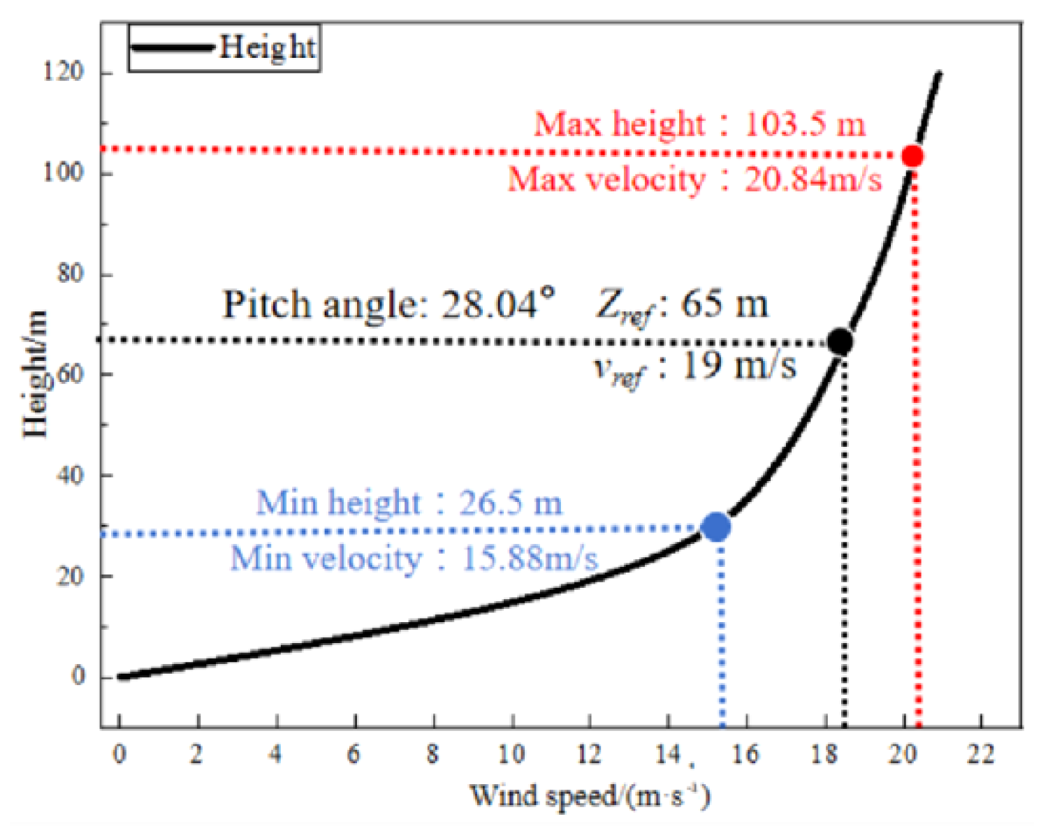
The wind speed distribution of the Huade Wind Farm of the Inner Mongolia Guoshui Group was considered for this study. We used the exponential wind shear function to describe the distribution. This study integrated calculations that are based on the measured data of the 65 m high wind measurement tower in the wind field; the incoming wind speed can be determined by applying the following equation:
v = v r e f ( Z Z r e f ) α
where v is the wind speed at height z, m/s; vref is the known wind speed at Zref, m/s; Zref is the height at the center of the hub, m; α is the wind shear coefficient, which is fitted according to the measured data and is 0.2.
Because the influence of strong wind load on the structural strength of wind turbine blades can not be ignored and combined with the local strong wind conditions of the wind farm, it is necessary to analyze the unsteady stress characteristics of wind turbine blades under strong wind conditions. According to the literature, it is necessary to define strong winds. According to the reference [26], winds with instantaneous wind speeds of 17 m/s or more (or visually estimated winds of eight or more) are strong winds. Therefore, vref is 19 m/s, Zref is 65 m, and the blade pitch angle is 28.04°. From this, the UDF (User Defined Function) of the shear wind at the entrance of the calculation domain is compiled to simulate the shear and flow of the wind turbine blade during operation. By combining the observations in Figure 4 and Equation 8, the maximum and minimum heights during the blade tip rotation are 103.5 m and 26.5 m, respectively. This corresponds to wind speeds of 20.84 m/s and 15.88 m/s. Based on the meteorological parameters of the wind field in December 2018, the air density is 1.147 kg/m3, the ambient temperature is 256.45 K, the atmospheric pressure is 86.4 KPa, and the turbulence is 0.07.
This investigation selected the Fluent double precision and SIMPLE algorithm for performing the calculations. The residual value is 10−4, and the difference method is a second-order upwind. The calculation selects a strong wind with a wind condition of 19 m/s. When the wind speed is greater than the rated wind speed and less than the maximum wind speed, the wind wheel rotates at the rated speed; then, the set speed is 19.8 rpm, and it takes 3.029 s for each rotation of the wind wheel. The calculation is performed every time the blade rotates 30°, and the corresponding transient calculation time step is 0.252 s. The wind wheel is set to rotate for 20 cycles. When the torque coefficient is stable, the 16th cycle aerodynamic load is introduced into the transient structure field, and the fluid–solid coupling method is used to solve the blade surface stress distribution. The consistency of the coupling solution is ensured by keeping the step length and total time of the transient structural field consistent with the calculation time of the fluent flow field.

3. Results and Discussion

3.1. Analysis of the Blade Equivalent Stress under Different Azimuth Angles

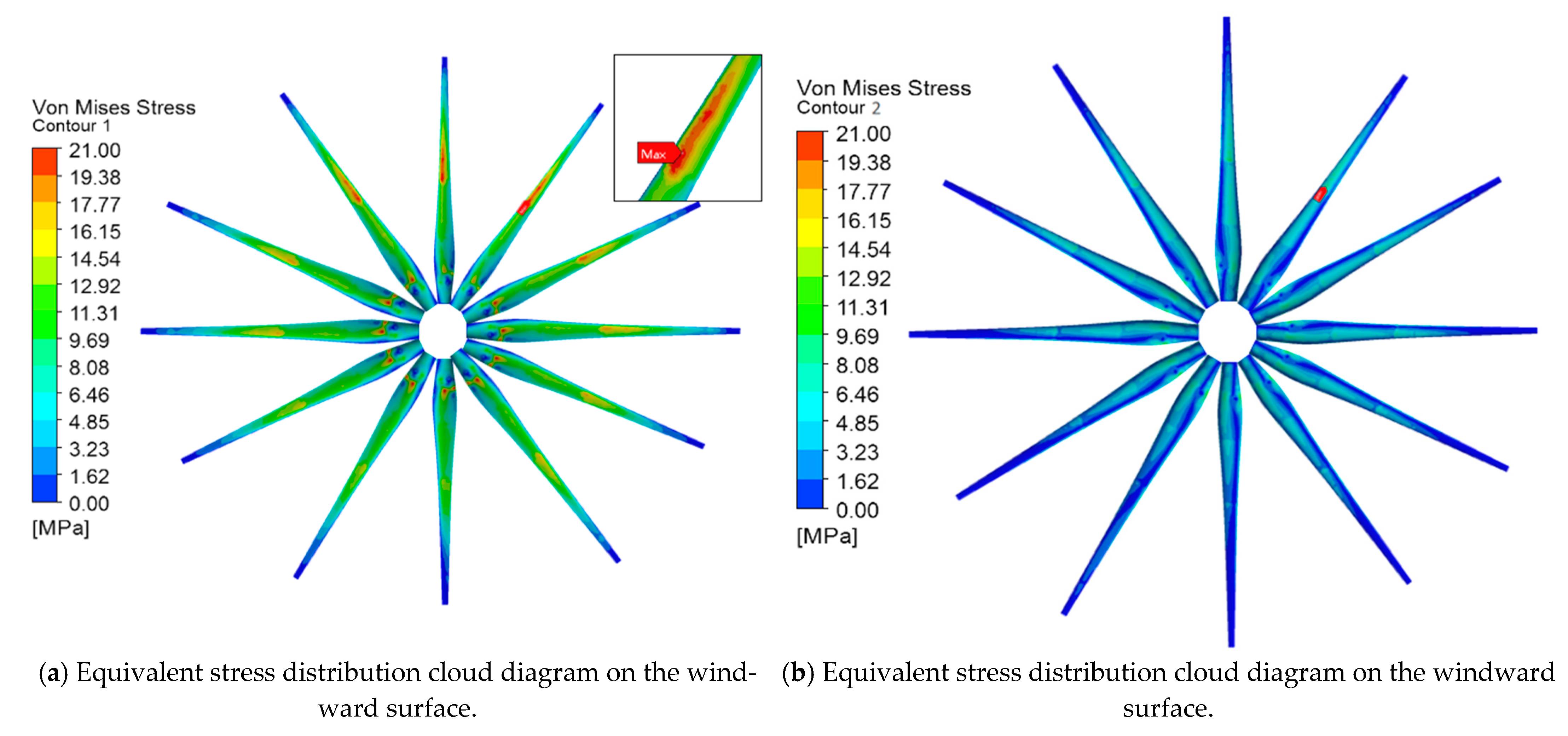
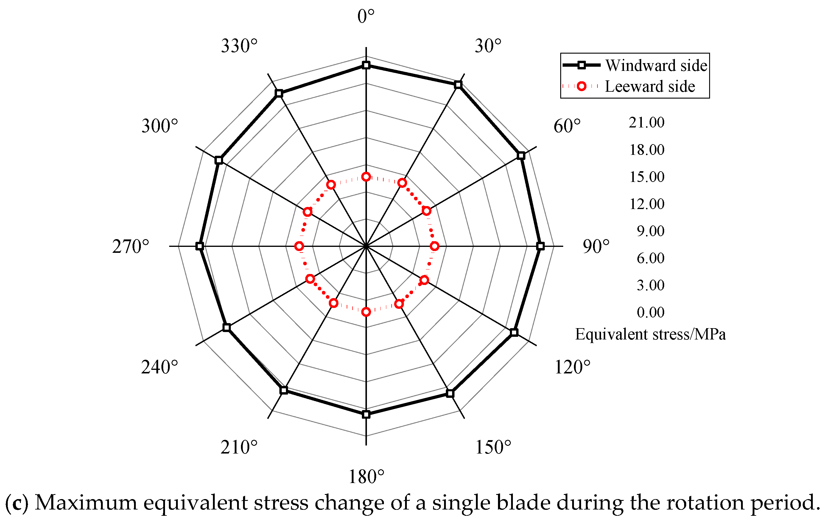
The vertical upwards of the blade tip is defined as an azimuth angle of 0°, and the clockwise direction is considered to be the positive direction of the rotation. The rotation period is equally divided into 12 parts, where each part represents 30°. After the calculation is completed, the equivalent stress cloud diagram and the maximum equivalent stress periodic change are extracted.
It can be observed from Figure 5 that under the same rotation period, the maximum equivalent stresses on the windward and leeward sides at an azimuth angle of 30° are 20.60 MPa and 8.09 MPa, respectively. The maximum equivalent stresses on the windward and leeward sides have an azimuth angle of 240° and they are 19.20 MPa and 7.23 MPa. The equivalent stress value of the first half cycle is generally greater than the second half cycle. Because of the shear flow, the stress increases with an increase in height; gravity does positive work in the first half cycle and negative work in the second half cycle. The equivalent stress on the windward surface is concentrated near the root and the middle of the blade; this concentration is caused by the force characteristics of the windward surface and the structure of the blade. The equivalent stress on the leeward surface appears in the transition zone at each layer section, which is due to the stress concentration and layering that is caused by the segmented position.
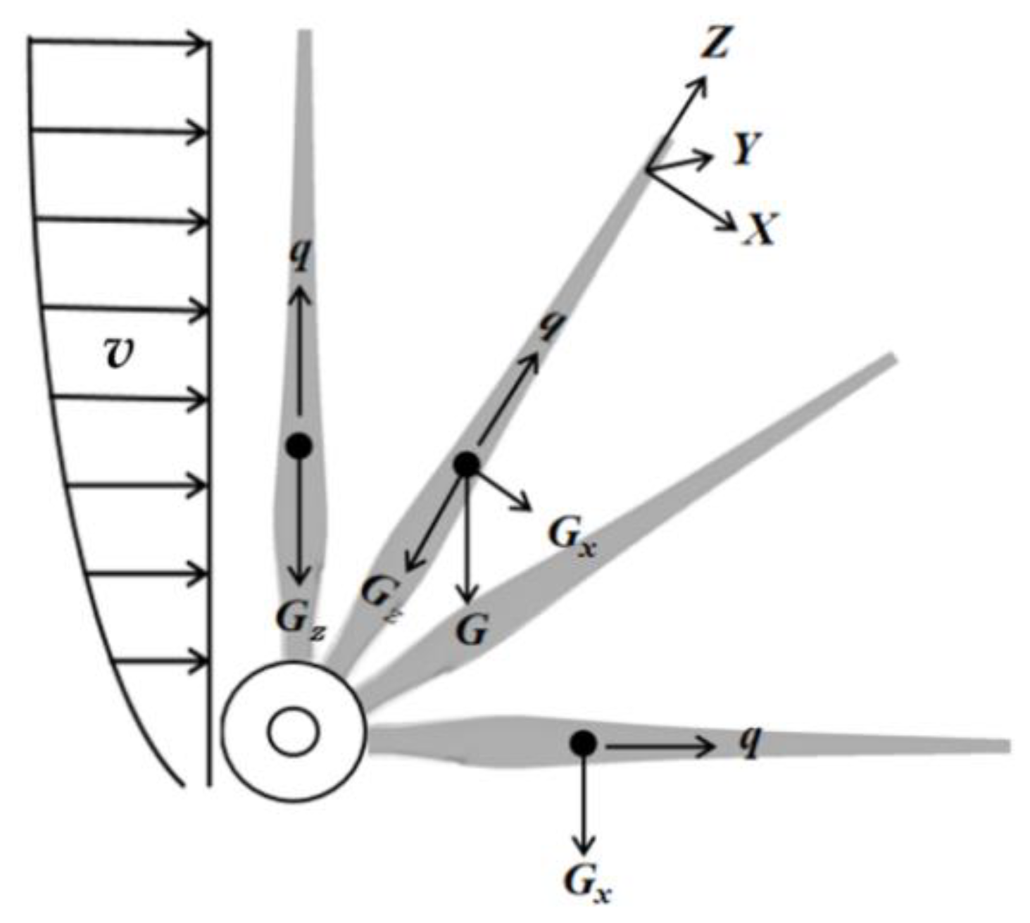
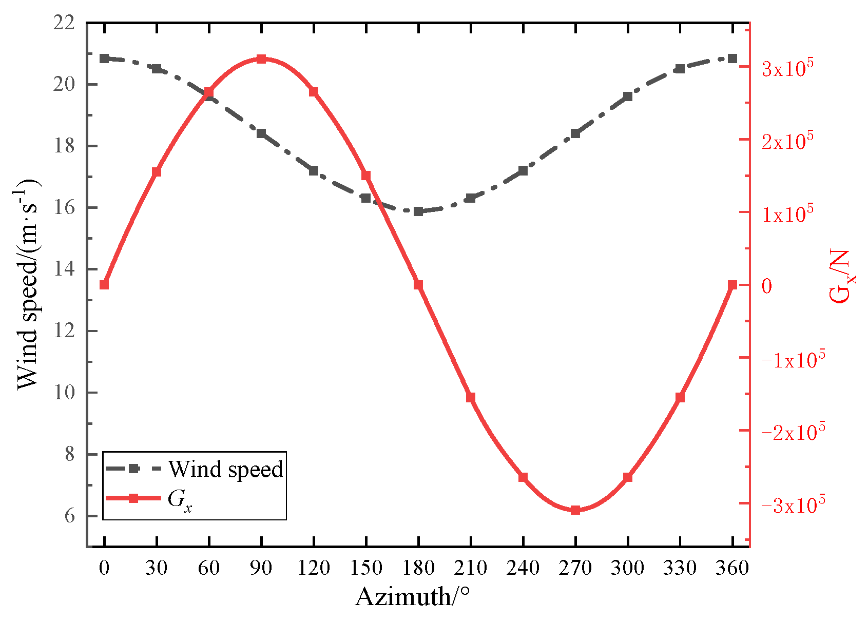
This study set the wind speed as v, the centrifugal force load as q, gravity as G, the spanwise component of gravity as Gz, and gravity along the blade rotation direction as Gx. The blade load distribution is shown in Figure 6. The wind speed v and Gx at a certain point ri (r/R = 0.5) of the monitoring blade are plotted in Figure 7, and the two change in the form of sine and cosine. When the blade rotates to the azimuth angle θ, the wind speed slowly decreases from 0° to 45°. Gx increases rapidly from 0° to 45° and reaches the maximum at 45°. The blade receives the largest force at 30°, which is reflected in the maximum equivalent stress of the blade at an azimuth angle of 30°, which is the largest.

3.2. Load Analysis of a Typical Blade Failure Area

The blade is susceptible to fatigue due to large aerodynamic loads on the windward side of the leading edge and weak tail edge. Therefore, it is important to explore the distribution of equivalent stress on the leading edge and the trailing edge of the blade. Under the condition of a 19 m/s wind speed, this study first carried out a spanwise equivalent stress analysis on the leading edge and trailing edge of the blade under an azimuth angle of 30° to find the typical stress concentration section.
It can be observed from Figure 8 that the equivalent stress at the trailing edge line of the blade is generally greater than the leading edge line. The span length of the blade/the full length of the blade is set to r/R. The equivalent stress at the trailing edge of the blade is generally higher than that at the leading edge, and it includes an r/R = 0.10 section, an r/R = 0.28 section, an r/R = 0.53 section, and r/R = 0.88 at the blade layer section. The abrupt peak value of the equivalent stress is due to the sharp change in the number of layers at the blade layer section, and the poor structural stability of the section, which makes the position more prone to stress concentration and damage that is attributed to sudden changes in the stress. At the same time, there are also stress mutation peaks in the r/R = 0.16 section and r/R = 60 section, which is due to the special aerodynamic shape of the blade. This leads to the distribution of the blade spanwise stress.
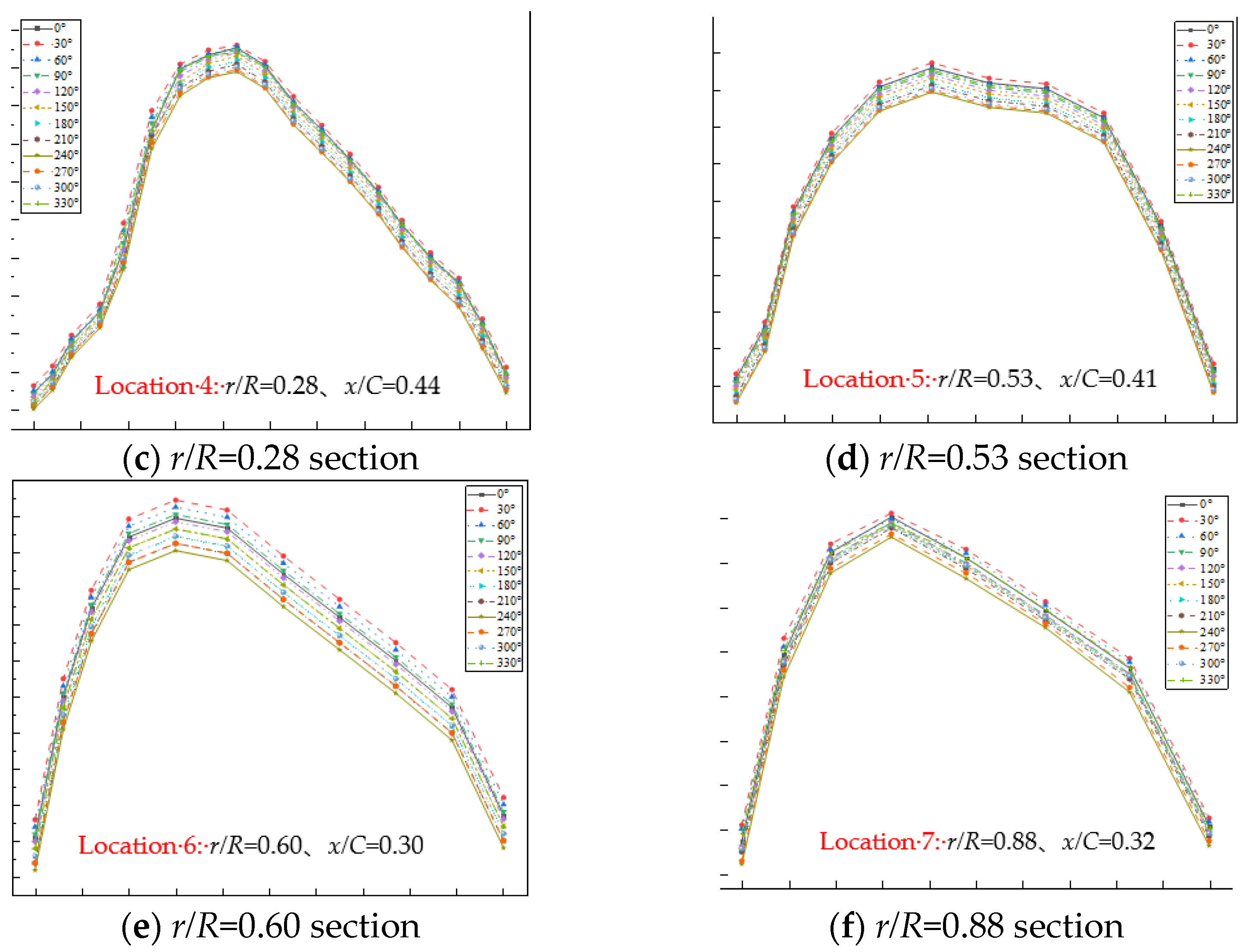
There are obvious equivalent stress peaks in the aforementioned six sections. In order to further explore the chordal distribution of the equivalent stress, the chordal equivalent stress analysis under one rotation cycle is performed on the six sections, as shown in Figure 9.
It can be observed from Figure 9 that each section has the maximum equivalent stress at an azimuth angle of 30°, and the changing trend of the equivalent stress along the chord direction of each section first increases and then decreases. The r/R = 0.10, 0.28, 0.53, and 0.88 sections are located in the pavement section, the number of plies has a sharp transition, and the superimposition of the multiple loads results in stress concentration peak in four sections. The equivalent stress at the section position is too concentrated, and the curve has a sudden peak. In particular, the r/R = 0.16 section is located in the transition area that is between the blade root circle and the blade root airfoil. The relatively large transition of the relative thickness results in large equivalent stress in the middle of the airfoil chord and near the trailing edge; the curve has two obvious peaks. The equivalent stress value of the r/R = 0.60 section is larger than the other five sections. The aerodynamic shape and structural characteristics of the blade at this position indicate that the section bears a large load and is prone to failure. According to the graph, six typical failure locations can be found in Table 5.
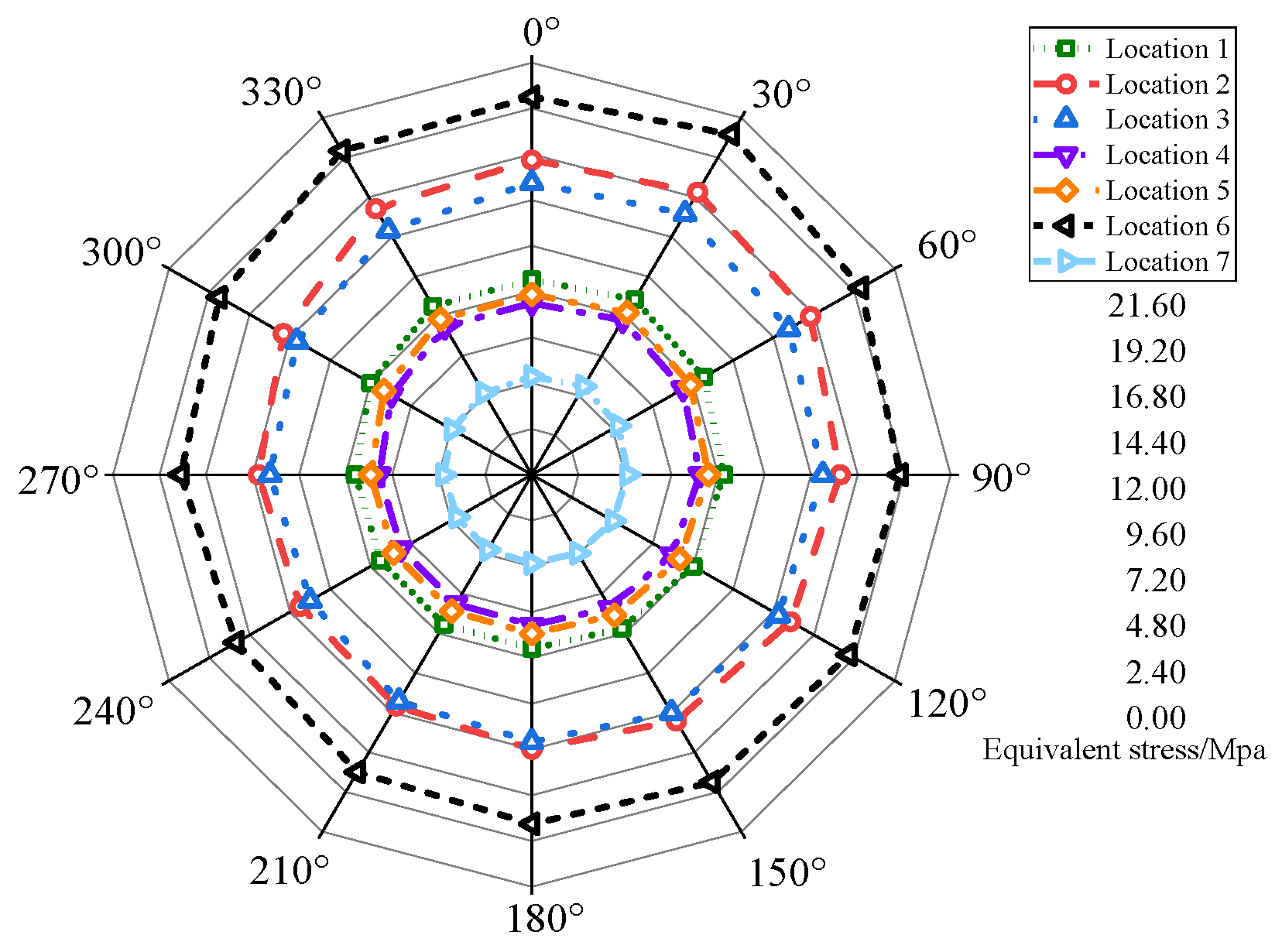
From Figure 10 and Table 5, it can be observed that the load when the blade rotates to different positions is quite different. The maximum value of the equivalent stress at each failure location is around a 30° azimuth angle, and the maximum equivalent stress value at Location 6 is 20.60 MPa. Compared with the incoming positive wind, under the action of a strong wind, when the blade runs from 0–60° and 300–360°, not only is the equivalent stress value large but the influence of the shear stress and normal stress cannot be ignored. Considering this, we explored the typical shear stress and normal stress distribution of the section.
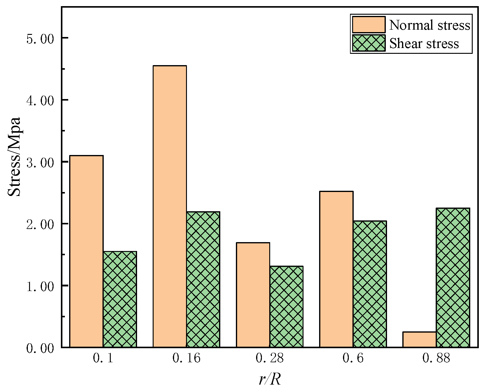
By analyzing the relationship between the positive and shear stress in Figure 11, it was determined that during the transition from the root to the tip, the normal stress shows a gradual decrease, whereas the change in the shear stress is relatively stable. The normal stress at r/R = 0.16 section near the blade root circle and the transition area of the airfoil is the maximum at 4.85 MPa. The normal stress at r/R = 0.88 is rapidly reduced to 0.35 MPa, and the maximum shear stress is 2.60 MPa, which is 7.5 times the maximum normal stress of the section. Based on the aforementioned analysis, it can be observed that excessive shear stress is an important factor that leads to the failure of blade roots and blade tips.
The composite material that is used for the blade is glass fiber reinforced plastic, and the strength of the blade ensures that the equivalent stress of the blade under a load cannot exceed the material damage limit [21].
σ max [ σ ] = σ s γ
When the safety factor γ is 3, σmax is the maximum stress of the blade; (σ) is the allowable stress of the blade, in which the value is 73.33 MPa; and σs is the yield stress of the blade, in which the value is 220 MPa.
According to Equation (9), the strength of the wind turbine blade is checked based on the maximum stress criterion. The results of the evaluation are shown in Table 6.
According to the calculated data in Table 6, it can be determined that under strong wind conditions where the speed is 19 m/s, the maximum blade stress value is 28.09% of the allowable stress. It can be observed that the wind turbine blades that are used in this study are theoretically safe and reliable.

3.3. Research and Investigations of Failure and Damage of the Typical Area Outside the Blade

There are so many techniques for wind turbine damage detection, such as based on strain measurement, vibration, thermography, etc. However, Strain and vibration measurements rely on sticking strain gauges to the blades, and the operation is difficult and dangerous for operators. Although thermal imaging technology has the advantage of not contacting wind turbine blades, it is vulnerable to environmental interference [27,28,29]. So the method of UAV(Unmanned aerial vehicle) damage detection is more safe and efficient.
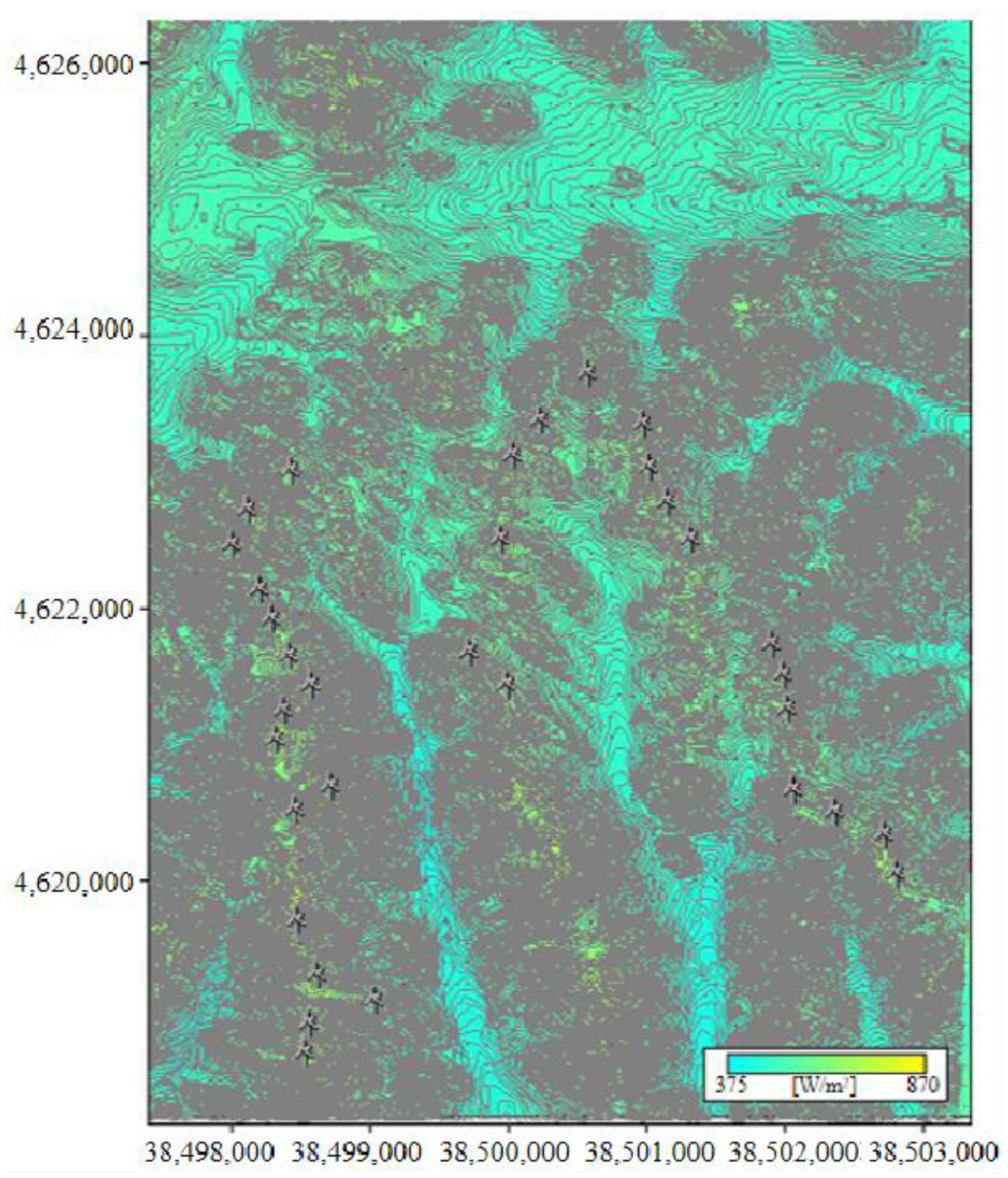
When the wind turbine is in a shutdown state, an unmanned aerial vehicle is used to inspect the blades of the wind turbine in service, and the typical external problems of the blades are highlighted through image processing technology. The experimental wind farm is the Huade wind farm that belongs to the Guoshui Group. The farm is located in Ulanqab City in the Inner Mongolia Autonomous Region. All wind turbine models consisted of WGTS1500A, and there were a total of 132 wind turbines. The total capacity of the fourth phase is 200 MW. The scale of each phase is 33 × 1.5 MW. The terrain of the site consists of low mountain hills, gentle slope hills, and there are a few buildings and trees at the site. By taking the first phase as an example, the layout of the wind turbines in the wind farm is shown in Figure 12.
As shown in Figure 12, it is significant that most wind turbines are distributed in places with a high wind power density. Before the experiment, the wind turbines that were to be tested were shut down, and the 132 wind turbines that consist of the WTGS1500(Wind turbine generator system1500) model and belong to the wind farm were inspected by drones. When the wind turbine is in a shutdown state, an unmanned aerial vehicle is used to inspect the blades of the wind turbine in service, and the typical external problems of the blades are highlighted through image processing technology. Finally, a series of blade damage pictures were collected. By combining the results of the blade stress concentration area that were obtained by a numerical simulation analysis and comparing the damage results that were observed on-site, we can comprehensively determine the cause of the blade damage, and provide guidance for the maintenance of the blade.
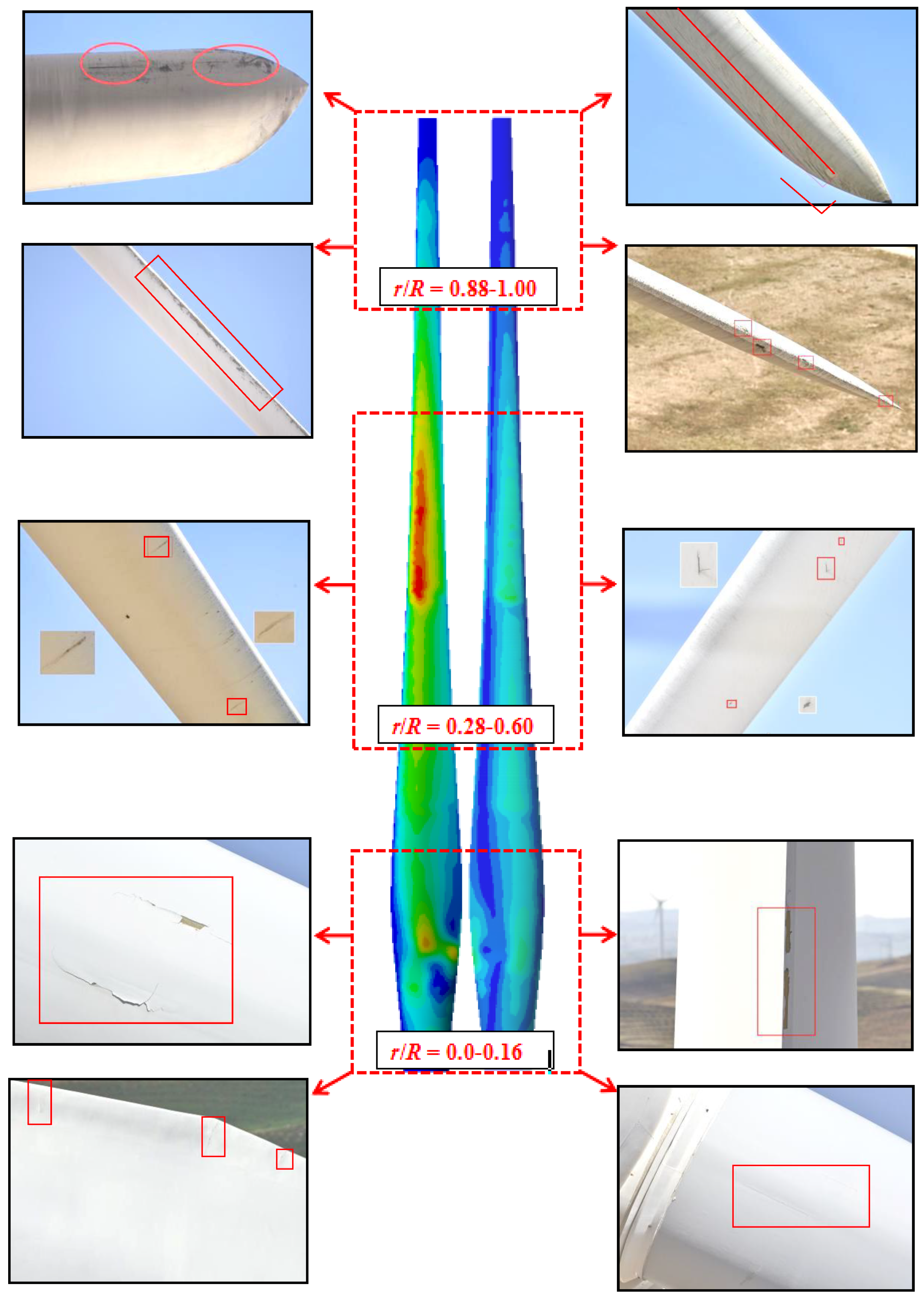
As shown in Figure 13, according to the distribution of the failure locations, this investigation divides the wind turbine blade into three regions along the span direction, namely the root region r/R = 0.00–0.16, the middle region r/R = 0.28–0.60, and the tip region r/R = 0.88–1.00. By taking a wind farm in western Inner Mongolia as a research sample, this study used an unmanned aerial vehicle that was equipped with a 60-megapixel lens. The blades of 132 wind turbines were inspected sequentially, and the common failure and damage forms in each area of the wind turbine blades at strong winds were summarized.
After inspecting a total of 396 blades from the 132 wind turbines in this wind farm, the failure damage was assessed. Figure 13 is the cloud diagram of the equivalent stress distribution of the wind turbine blade at 30° azimuth calculated by the fluid-structure coupling numerical simulation, which is compared and correlated with the actual damaged area of the blade. The types of failure damage that appear in order from light to heavy are: paint peeling, oil pollution, scratching injuries, bulges, cracks, cracks in the gel coat, and lightning damage. The afore-mentioned damages are the most common and frequent failure damage modes for this type of 1.5 MW wind turbine blade in this wind farm.
The types of blade damage and the common types of wind turbine blade damage are summarized. In this batch of wind turbine blade inspections, a total of 8917 images were taken, which include 2180 blade damage images and 6737 images without blade damage. According to the calculations, damaged images account for 24.45% of the total number of images (most of them were paint peeling and oil stains, etc.), which contain 1988 images, that account for 22.29% of the total number of images; the rest are scratches, cracks, gel coat cracking, lightning strikes, and bulges, which consist of 192 images. Among them, the damage that is caused by stress includes cracks and gel coat cracking in about 58 images, which accounts for 0.65% of the total number of images.
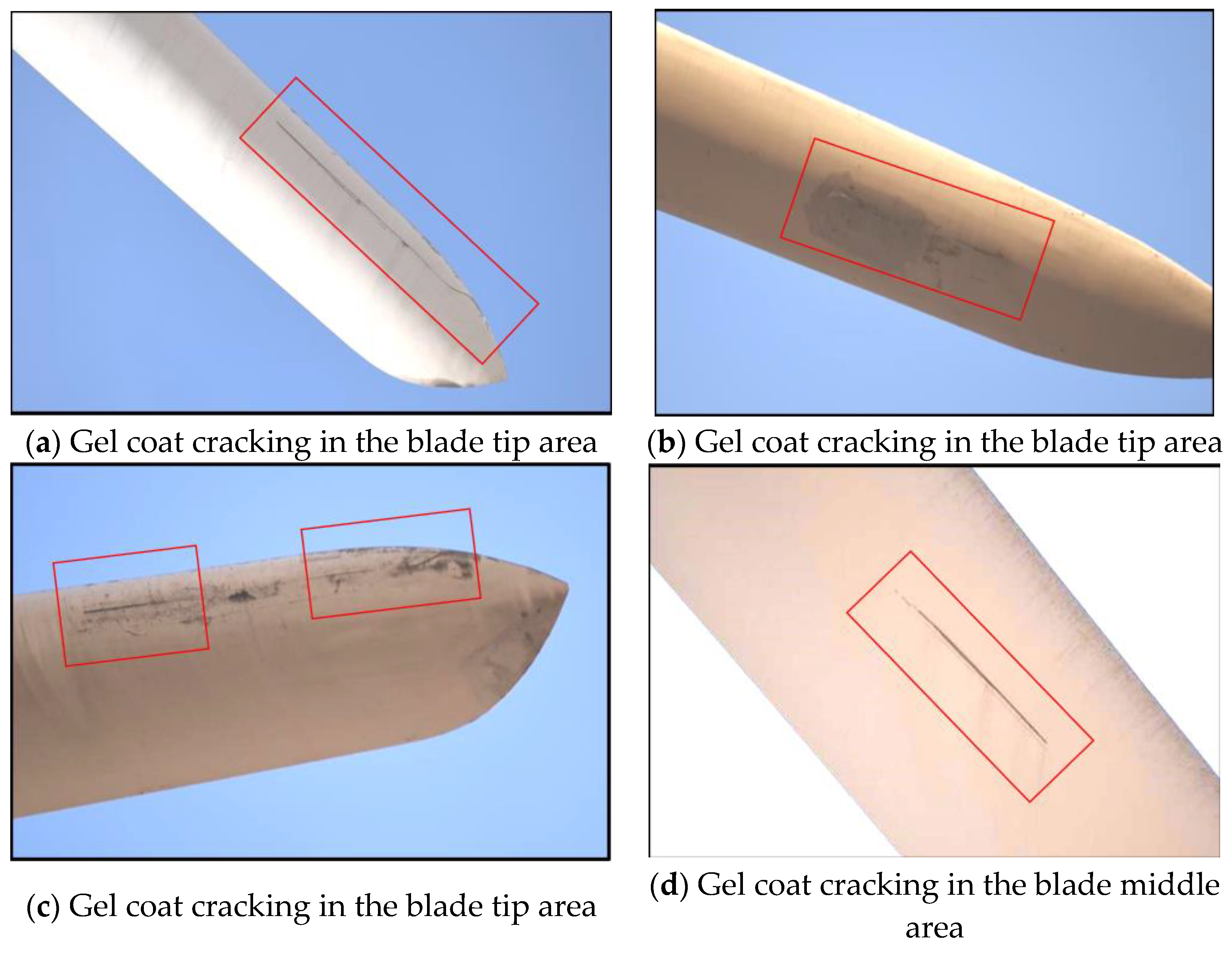
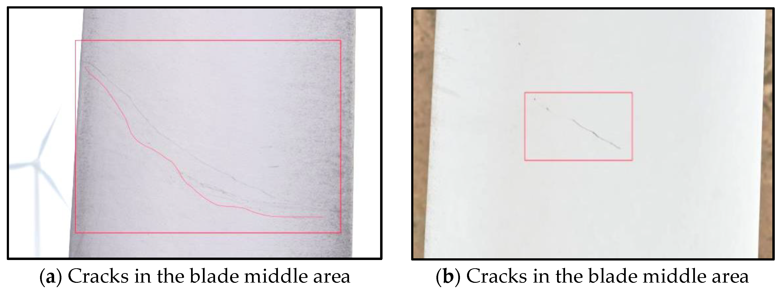
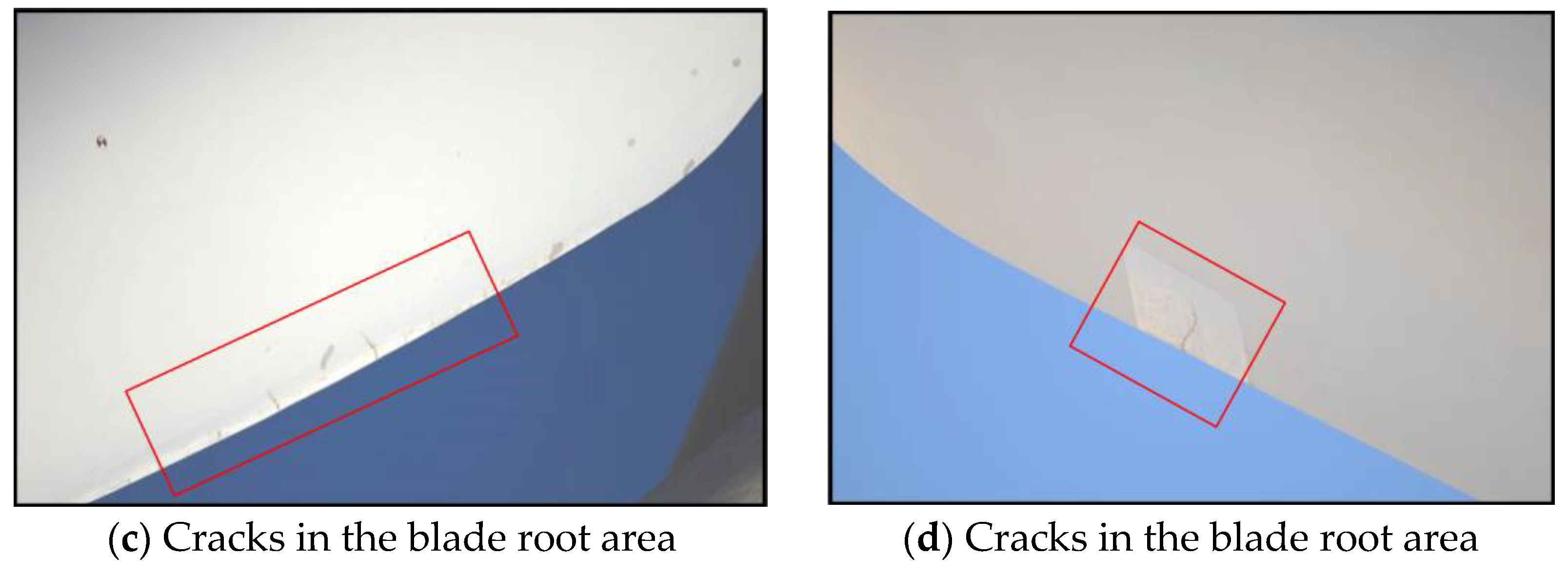
Based on the stress distribution of the wind turbine blades in the previous subsection, after identifying and classifying the captured damage images, the damage of the blade that is caused by stress includes cracks, gel coat cracks; the various types of damage that were counted. Figure 14 shows the gel coat cracking phenomenon that is caused by stress; Figure 15 displays the crack image of the blade that is caused by stress.
Among them, the frequency of the various types of damage = the number of various types of damage/the total number of damage. The frequency for a certain type of damage in each area = the number of certain types of damage in each area/the total number of damage for a certain type. The failure conditions are shown in Table 7 and Table 8.
It can be observed from Table 7 that by screening the damage images of the wind turbine blade failure that is due to stress, the most frequent failure type are cracks. The number of images is 49, which accounts for 84.48% of the damage that is caused by stress. The gel coat crack is another form of failure caused by stress. The number of images is nine, which accounts for 15.52% of the damage that is caused by stress.
According to the classification of the typical areas, we can summarize the frequency of the main failure damage that is caused by the stress in each area, and this is summarized in Table 8. There were nine cases of gel coat cracking; seven times, it occurred along the tip of the blade, and the frequency was 77.78%. It occurred two times along the middle of the blade with a frequency of 22.22%; however, no gel coat cracking occurred at the root of the blade. A total of 49 cracks appeared in the root of the blade, and the number and frequency were 43 times and 87.75%, respectively. There were three cracks in the blade, and the frequency of occurrence was 10.20%. The number of cracks appeared less at the tip of the blade, in which the frequency was once, and the probability was 2.05%. It can be observed that the main failure mode of the blade tip area is gel coat cracking, the root area of the blade is the main failure mode, and gel coat cracking and cracking in the blade area occur, but the frequency is low.
According to the image statistics, when considering all the failure types that are caused by stress, the frequency of cracks in the root area (r/R = 0.00–0.16) is as high as 87.75%. However, the cracks in this area are relatively slight and they mostly exist in the surface layer of the trailing edge of the blade root area. These cracks are insufficient to bring destructive hazards to the wind turbine blade. Regular repairs for this crack type can maintain the normal operation of the wind turbine, the maintenance is convenient, and the cost is low. However, the frequency of cracks in the mid-blade area (r/R = 0.28–0.60) also reached 10.20%. According to the results of the field survey, once a chordal crack in the mid-blade area appears, it may be fatal to the blade and the whole machine. Because of the damage, the maintenance is inconvenient and high-cost.
This investigation compared the results of the blade stress concentration area that was obtained by the numerical simulation analysis with the blade damaged area that was obtained from the field observation. It was determined that the actual damage position of the blade is mostly near the stress concentration area that is calculated by the numerical simulation. In addition, the damage failure mode can confirm the blade force characteristics. The results can guide drone inspections.

4. Conclusions

This paper discusses the fluid–structure coupling calculation method in order to explore the stress distribution of a 1.5 MW wind turbine during strong winds. By combining the numerical simulation results and the UAV observation experiments, we can comprehensively determine the failure area and failure mode of the blade and draw the following conclusions:
  • The maximum stress of the blade near a 30° azimuth angle is 20.6 MPa. This is because the resultant force on the blade is the largest when the azimuth angle is 30°. By having an azimuth angle of 30° there are obvious equivalent stress peaks in the six sections of the blade, and the most vulnerable position is r/R = 0.60 and x/C = 0.30. The maximum stress value of the blade under strong wind conditions is 28.09% of the allowable stress. Theoretically, the blade structure is safe.
  • When considering the UAV’s inspection of 132 wind turbines in the wind farm, 2145 failure images of the blades were collected. The damaged images account for 24.45% of the total number of images (i.e., paint peeling and oil pollution are the most frequent failure types at the end of the wind farm’s service, which appear 1988 times and account for 22.29% of the total number of image samples). The rest include scratches, cracks, bulges, gel coat cracks and so on, which resulted in a total of 192 photos.
  • Cracks appeared 49 times in total, with more occurrences at the root of the blade, 43 times with a frequency of 87.75%, respectively. There were three occurrences along the middle of the blade, with a frequency of 10.20%; and there were fewer occurrences at the tip of the blade, which occurred only once and the probability was 2.05%. Therefore, the main failure mode of the blade tip is gel coat cracking, the root of the blade is mainly cracked, and gel coat cracking and cracking in the blade occur, but the frequency is low.
  • It was determined that the actual damage position of the blade is mostly near the stress concentration area that is calculated by the numerical simulation. The damage failure mode can confirm the force characteristics of the blade. These results can provide guidance for drone inspections.

Author Contributions

K.T. contributed to the conception of the study and wrote the manuscript. L.S. reviewed and edited the manuscript. Y.C. was responsible for preparing the methodology. X.J. was responsible for the technical support. R.F. provided the experimental data support. R.T. helped perform the analysis with constructive discussions. All authors have read and agreed to the published version of the manuscript.

Funding

This research was funded by the Inner Mongolia Science and Technology Project Plan (2019), which was funded by the Department of Science and Technology in the Inner Mongolia Autonomous Region. (No grant number).

Data Availability Statement

Not applicable.

Acknowledgments

The wind speed model and wind field environmental data that were selected for the numerical simulation in this article were provided by the Inner Mongolia Electric Power Research Institute Branch of the Inner Mongolia Electric Power (Group) Co., Ltd. and the Guoshui Group Huade Wind Power Co., Ltd. We would like to express our sincere thanks to them.

Conflicts of Interest

The authors declare no conflict of interest.

Abbreviations

ACP ANSYS Composite PrepPost
αthe wind shear coefficient
EElastic Modulus
FRPFiber-reinforced plastic
GShear modulus
GGravity
xChord length along chordwise
CChord length
rBlade length along spanwise
RBlade length
UDFUser-Defined Function
vPoisson’s ratio
vWind speed
GzSpanwise component of gravity
GxGravity along the blade rotation direction
vrefKnown wind speed at Zref
ZrefHeight at the center of the hub
qCentrifugal force load
θAzimuth angle

References

  1. Santo, G.; Peeters, M.; Van Paepegem, W.; Degroote, J. Dynamic load and stress analysis of a large horizontal axis wind turbine using full scale fluid-structure interaction simulation. Renew. Energy 2019, 140, 212–226. [Google Scholar] [CrossRef]
  2. Zhu, J.; Cai, X.; Pan, P.; Gu, R.R. Static and Dynamic Characteristics Study of Wind Turbine Blade. Adv. Mater. Res. 2012, 433-440, 438–443. [Google Scholar] [CrossRef]
  3. Fernandez, G.; Usabiaga, H.; Vandepitte, D. An efficient procedure for the calculation of the stress distribution in a wind turbine blade under aerodynamic loads. J. Wind Eng. Ind. Aerodyn. 2018, 172, 42–54. [Google Scholar] [CrossRef]
  4. Jiang, X.; Gao, Z.; Wang, J.; Bai, Y.; Yan, M.; Wang, X. Experiment on correlation of wind turbine strain and tower vibration. J. Drain. Irrig. Mach. Eng. 2017, 35, 685. [Google Scholar]
  5. Kim, H.-I.; Han, J.-H.; Bang, H.-J. Real-time deformed shape estimation of a wind turbine blade using distributed fiber Bragg grating sensors. Wind Energy 2014, 17, 1455–1467. [Google Scholar] [CrossRef]
  6. Zhang, J.; Guo, L.; Wu, H.; Zhou, A.; Hu, D.; Ren, J. The influence of wind shear on vibration of geometrically nonlinear wind turbine blade under fluid–structure interaction. Ocean Eng. 2014, 84, 14–19. [Google Scholar] [CrossRef]
  7. Cheng, Y.; Xue, Z.; Jiang, T.; Wang, W.; Wang, Y. Numerical simulation on dynamic response of flexible multi-body tower blade coupling in large wind turbine. Energy 2018, 152, 601–612. [Google Scholar] [CrossRef]
  8. Zhang, J.P.; Li, D.L.; Liu, Y.; Wu, H.L.; Ren, J.X.; Pan, W.G. Dynamic Response Analysis of Large Wind Turbine Blade Based on Davenport Wind Speed Model. Adv. Mater. Res. 2011, 347-353, 2330–2336. [Google Scholar] [CrossRef]
  9. Zhou, B.; Wang, X.; Zheng, C.; Cao, J.; Zou, P. Finite Element Analysis for the Web Offset of Wind Turbine Blade. IOP Conf. Ser. Earth Environ. Sci. 2017, 63, 12011. [Google Scholar] [CrossRef] [Green Version]
  10. Choudhury, S.; Sharma, T.; Shukla, K. Effect of orthotropy ratio of the shear web on the aero-elasticity and torque generation of a hybrid wind turbine blade. Renew. Energy 2017, 113, 1378–1387. [Google Scholar] [CrossRef]
  11. Dimitrov, N.; Natarajan, A.; Kelly, M. Model of wind shear conditional on turbulence and its impact on wind turbine loads. Wind Energy 2014, 18, 1917–1931. [Google Scholar] [CrossRef]
  12. Ageze, M.B.; Hu, Y.; Wu, H. Comparative Study on Uni- and Bi-Directional Fluid Structure Coupling of Wind Turbine Blades. Energies 2017, 10, 1499. [Google Scholar] [CrossRef] [Green Version]
  13. Zhu, R.-S.; Zhao, H.-L.; Peng, J.-Y.; Li, J.-P.; Wang, S.-Q.; Zhao, H. Numerical Investigation on Fluid-structure Coupling of 3 MW Wind Turbine Blades. Int. J. Green Energy 2015, 13, 241–247. [Google Scholar] [CrossRef]
  14. Bae, S.-Y.; Kim, Y.-H. Structural design and analysis of large wind turbine blade. Mod. Phys. Lett. B 2019, 33, 1940032. [Google Scholar] [CrossRef]
  15. Ullah, H.; Ullah, B.; Riaz, M.; Iqbal, M.; Badshah, A. Structural Analysis of a Large Composite Wind Turbine Blade under Extreme Loading. In 2018 International Conference on Power Generation Systems and Renewable Energy Technologies, Islamabad, Pakistan, 10–12 September 2018; IEEE: Piscataway, NJ, USA, 2018. [Google Scholar]
  16. Shen, X.; Zhu, X.; Du, Z. Wind turbine aerodynamics and loads control in wind shear flow. Energy 2011, 36, 1424–1434. [Google Scholar] [CrossRef]
  17. Fu, B.; Zhao, J.; Li, B.; Yao, J.; Teifouet, A.R.M.; Sun, L.; Wang, Z. Fatigue reliability analysis of wind turbine tower under random wind load. Struct. Saf. 2020, 87, 101982. [Google Scholar] [CrossRef]
  18. Guo, S.; Li, Y.; Chen, W. Analysis on dynamic interaction between flexible bodies of large-sized wind turbine and its response to random wind loads. Renew. Energy 2020, 163, 123–137. [Google Scholar] [CrossRef]
  19. Wang, H.; Ke, S.T.; Wang, T.G.; Zhu, S.Y. Typhoon-induced vibration response and the working mechanism of large wind turbine considering multi-stage effects. Renew. Energy 2020, 153, 740–758. [Google Scholar] [CrossRef]
  20. Boujleben, A.; Ibrahimbegovic, A.; Lefrançois, E. An efficient computational model for fluid-structure interaction in application to large overall motion of wind turbine with flexible blades. Appl. Math. Model. 2020, 77, 392–407. [Google Scholar] [CrossRef]
  21. Peeters, M.; Santo, G.; Degroote, J.; Van Paepegem, W. Comparison of Shell and Solid Finite Element Models for the Static Certification Tests of a 43 m Wind Turbine Blade. Energies 2018, 11, 1346. [Google Scholar] [CrossRef] [Green Version]
  22. Wang, L.; Quant, R.; Kolios, A. Fluid structure interaction modelling of horizontal-axis wind turbine blades based on CFD and FEA. J. Wind Eng. Ind. Aerodyn. 2016, 158, 11–25. [Google Scholar] [CrossRef] [Green Version]
  23. Tran, T.; Kim, D.; Song, J. Computational Fluid Dynamic Analysis of a Floating Offshore Wind Turbine Experiencing Platform Pitching Motion. Energies 2014, 7, 5011–5026. [Google Scholar] [CrossRef]
  24. Steijl, R.; Barakos, G. Sliding mesh algorithm for CFD analysis of helicopter rotor-fuselage aerodynamics. Int. J. Numer. Methods Fluids 2008, 58, 527–549. [Google Scholar] [CrossRef]
  25. Tian, K.; Song, L.; Jiao, X.; Feng, R.; Chen, Y.; Tian, R. Aeroelastic stability analysis and failure damage evaluation of wind turbine blades under variable conditions. Energy Sources Part A Recover. Util. Environ. Eff. 2021, 1–18. [Google Scholar] [CrossRef]
  26. Song, L.; Li, Q.; Chen, W.; Qin, P.; Huang, H.H.; Yuncheng, H. Wind characteristics of a strong typhoon in marine surface boundary layer. Wind Struct. 2012, 15, 1–15. [Google Scholar] [CrossRef] [Green Version]
  27. Mao, Y.; Wang, S.; Yu, D.; Zhao, J. Automatic image detection of multi-type surface defects on wind turbine blades based on cascade deep learning network. Intell. Data Anal. 2021, 25, 463–482. [Google Scholar] [CrossRef]
  28. Xu, D.; Wen, C.; Liu, J. Wind turbine blade surface inspection based on deep learning and UAV-taken images. J. Renew. Sustain. Energy 2019, 11, 053305. [Google Scholar] [CrossRef]
  29. Toft, H.S.; Branner, K.; Berring, P.; Sorensen, J.D. Defect distribution and reliability assessment of wind turbine blades. Eng. Struct. 2011, 33, 171–180. [Google Scholar] [CrossRef]
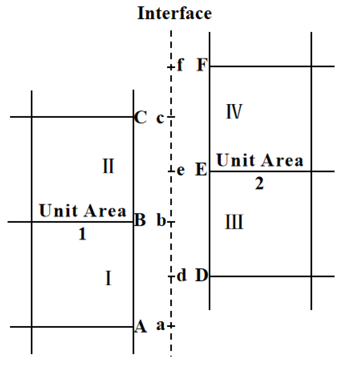
Figure 1. Schematic diagram of the sliding grid principle [24].
Energies 15 01339 g001
Figure 2. Layering design of the 1.5 MW wind turbine blade used in this study.
Energies 15 01339 g002
Figure 3. Computational domain mesh comprising unstructured tetrahedral grids to construct the physical model of the wind wheel.
Energies 15 01339 g003
Figure 4. Inflow wind speed profile.
Energies 15 01339 g004
Figure 5. Equivalent stress distribution during one cycle.
Energies 15 01339 g005aEnergies 15 01339 g005b
Figure 6. Spanwise load distribution.
Energies 15 01339 g006
Figure 7. Distribution of the gravity and wind speed at ri.
Energies 15 01339 g007
Figure 8. Equivalent stress distribution when it is spanwise at a 30° azimuth angle.
Energies 15 01339 g008
Figure 9. Stress of a typical failure section at different azimuth angles.
Energies 15 01339 g009aEnergies 15 01339 g009b
Figure 10. Stress distribution at a typical position.
Energies 15 01339 g010
Figure 11. Stress under a 30° azimuth angle.
Energies 15 01339 g011
Figure 12. Schematic diagram of the layout of the wind turbine units.
Energies 15 01339 g012
Figure 13. Common damage and failure of the blades.
Energies 15 01339 g013
Figure 14. Cracking of the gel coat caused by stress.
Energies 15 01339 g014
Figure 15. Cracks caused by stress.
Energies 15 01339 g015aEnergies 15 01339 g015b
Table 1. Parameters of the 1.5 MW wind turbine.
NameSpecificationsNameSpecifications
AirfoilProvided by manufacturerRated power P/MW1.5
Number of blades /N3Rated speed n/rpm19.8
Hub center height H/m65Rated wind speed v/m·s−112
Hub diameter d/m2Rated tip speed ratio λ8.5
Wind wheel diameter D/m77Cut-in wind speed v/m·s−13
Wind wheel quality m/t30.1Cut-out wind speed v/m·s−125
Table 2. Material properties.
MaterialElastic Modulus/MPaPoisson’s RatioShear Modulus/MPa
E11E22E33v12v23v13G12G23G13
FRP39,000860086000.280.470.28380029303800
Table 3. Grid independence verification about CFD model.
Wind SpeedGrid Numbers/Ten Thousand
3.6 m/s3404305206207008509001070
Maximum pressure/Pa164165167169172175175175
19 m/s3404305206207008509001070
Maximum pressure/Pa15731587160416241646167416741674
21.1 m/s3404305206207008509001070
Maximum pressure/Pa16181643166816941720174317431743
Table 4. Grid independence verification about CFD model.
Wind SpeedGrid Numbers/Ten Thousand
19 m/s75819098105109109109
Maximum
Equivalent stress
/Mpa
19.219.519.720.320.620.620.620.6
Maximum displacement/m0.560.580.590.610.630.630.630.63
Table 5. Failure location and stress.
LocationFailure LocationMax Equivalent Stress/MPaAzimuth Angle of the Maximum Equivalent Stress
Location 1r/R = 0.10
x/C = 0.53
10.60Around 30°
Location 2r/R = 0.16
x/C = 0.52
17.10Around 30°
Location 3r/R = 0.16
x/C = 0.88
15.80Around 30°
Location 4r/R = 0.28
x/C = 0.44
9.36Around 30°
Location 5r/R = 0.53
x/C = 0.41
9.74Around 30°
Location 6r/R = 0.60
x/C = 0.30
20.60Around 30°
Location 7r/R = 0.88
x/C = 0.32
5.28Around 30°
Table 6. Strength check of the blade.
Location σ max ( σ )
Location 114.45%
Location 223.32%
Location 321.55%
Location 412.76%
Location 513.28%
Location 628.09%
Location 77.20%
Table 7. Failures of the blade caused by stress.
Damage Types Caused by StressGel Coat CrackingCracks
Damage numbers58
Damage type numbers949
Frequency15.52%84.48%
Table 8. Frequency of most common types of failurs of blades.
Damage TypesGel Coat CrackingCracks
Typical areaNumberFrequencyNumberFrequency
Blade root
r/R = 0.00–0.16
00.00%4387.75%
Blade middle
r/R = 0.28–0.60
222.22%510.20%
Blade tip
r/R = 0.28–0.60
777.78%12.05%
Publisher’s Note: MDPI stays neutral with regard to jurisdictional claims in published maps and institutional affiliations.