Review

Dynamic Equivalents in Power System Studies: A Review

Department of Power System and Control, Faculty of Electrical Engineering, Silesian University of Technology, 44-100 Gliwice, Poland
*
Author to whom correspondence should be addressed.
Energies 2022, 15(4), 1396; https://doi.org/10.3390/en15041396
Submission received: 14 December 2021 / Revised: 17 January 2022 / Accepted: 11 February 2022 / Published: 14 February 2022

Abstract

:
In this paper, the available methods and procedures for creating equivalents for the analysis of electromagnetic transients in power systems are presented and discussed. General requirements of power system representation during simulation of electromagnetic transients are shown. The main available procedures are shown, along with an assessment of their advantages and disadvantages. Methods to search for the optimal replacement of structures in time and frequency domains are discussed. Optimization and direct methods in the frequency domain are presented. Each of these methods is discussed with respect to their possible use in determining the structure of the equivalent circuit for the study of electromagnetic phenomena. Methods to reduce a complex power system, as one of the approaches to determining the structure and parameters of the equivalent circuit, are also presented. Contraindications to the search for equivalents in the frequency domain to study electromagnetic transients are discussed. An analysis of methods for the identification of parameters of the equivalents is presented. The latest advances in the search for the structure and parameters of equivalents are presented, particularly the use of artificial neural networks in the process of replacing parts of systems. Finally, the analyses conducted in this study, together with recommendations regarding the choice of the procedure during the search for equivalents for the analysis of electromagnetic transient phenomena, are summarized.

1. Introduction

Historical Review of Research

The currently operating interconnected power systems cover large geographic areas and millions of devices. For a large complex system, its complete mapping for the analysis of electromagnetic transients is neither necessary nor practically possible. When studying dynamic phenomena in a system, the main focus is on waveforms occurring only in a certain part of the system. Very often, this part is defined as the internal system, and the rest is defined as the external system. Static and dynamic reduction of the external system or its equivalent is a process of reducing the complexity of external models of the system while maintaining its influence on the obtained test results. In this way, complex system models can be significantly reduced with satisfactory accuracy with regard to a given phenomenon.
It should be noted that in some cases, the area of interest is limited to a network supplied by a single system, as in Figure 1a. When performing calculations (short-circuit or flow-through), only a small part of the entire large power grid is usually of interest. The question is whether it is correct to calculate the size in a small part of the network without taking into account the influence of the rest of the system. The reality, however, is more complex, as shown in Figure 1b,c. The situation in Figure 1c is particularly complicated but the most realistic. The examined object is in the middle of a system in which there are mutual connections and dependencies.
The network model contains replacement elements corresponding to the reduced part of the power supply system. Mistakes are frequently made, typically by creating a model that is too precise or simplifying it too radically. Of course, the most reliable analysis results are obtained on the basis of measurements in a real power system (with the provision of appropriate measuring devices). Unfortunately, in the case of studying electromagnetic transient phenomena, which are most often a consequence of disturbances, conducting measurements is very rare for economic, technical and organizational reasons.
These measurements are carried out in two ways:
  • Disturbances, for example, short-circuits in the line, are forced, and measurements are made at various points in the system, e.g., at the place where the protection system is installed;
  • Measurement devices connected to selected nodes record waveforms during disturbances (for which they are “waiting”).
In the first case, it is possible to select a specific situation (type and place of disturbance); however, safety considerations require the introduction of many limitations in order to avoid consequences resulting from possible fault development. Constraints cause the disconnection of parts of the system, the shutdown of some loads, the need to carry out tests at certain times, etc. In the second case, measurements of real phenomena in the original system are registered without restrictions. However, these are “random” waveforms that, even over a dozen or so years, are not sufficient for a comprehensive analysis.
The advantage of computer simulations is that it is possible to force faults of various types anywhere in the power system without any risk to its further operation. Until recently, most of the research was carried out in complex systems by replacing a large part of the system with simple impedances calculated from the short-circuit power of these systems. This approach is only acceptable for very simplified transient analyses. The biggest problem in such cases is the determination—usually based on an experiment—of how much of the system needs to be modeled accurately when replacing the remainder with the equivalent circuit. For many years, attempts have been made to find a universal solution to this issue. According to [1], it is recommended to include elements in branches up to two nodes adjacent to the node to which the tested object is connected. However, such a solution in the case of a very dense network containing many transmission lines does not guarantee the production of exactly the same results as in the real system.
Generally, therefore, a power system is represented by internal and external networks during analyses. Internal networks are modeled with an accurate mapping of all properties that are important in the analysis of a given phenomenon. The external system may be represented on the basis of a reduced substitute or a substitute structure determined on the basis of available time- or frequency-domain methods. For the analysis of phenomena in steady states, e.g., flow calculations, the external system frequently remains unreduced, which, however, due to the currently developed technology of computing machines, is not a major problem for very complex systems. However, there are limitations to using replacements of external systems: such a system can only be representative for a limited scope of research; it is not possible to account for changing conditions in this system. It is also impossible to take into account the influence of changes and phenomena occurring in the internal system on the structure and parameters of the substitute external system. This would require the use of a permanent update of the external replacement system parameters.
It is understandable that since there are fundamental differences in the mapping of system elements for different phenomena, the approach to creating substitute patterns for each of these phenomena will also be different. The need to create substitute diagrams for system analysis in various states has long been raised in many studies conducted around the world [2,3,4,5,6,7]. Historically, the equivalence of large power systems, including for steady states, resulted mainly from limited computational possibilities (limited computer memory and low speed of processors), which significantly slowed down the analysis in a complex power system.
The construction of equivalent diagrams for steady states (power flow and flow of steady short-circuit currents) was based on the reduction of the external system to a simple equivalent system. Methods for reducing complex systems for steady-state analysis are well developed in the literature. Ward’s method [8] has long been one of the most frequently used methods. This method has many disadvantages, including that it does not take into account the reactive power variability in the substitute system (created after the reduction of the external system), which is important in the case of power flow calculations. Attempts to remedy this inconvenience are reflected in methods developed later, such as REI [9], the Ward equation with buffer [10] or Ward’s extended method [11].
Equivalence methods for steady states were also used in older studies for stability calculations [12]. With technological development, and thus with the increased computing capabilities of computers (faster processors and increased memory), the so-called dynamic reduction of the power system was increasingly applied. An improved REI method was proposed [13] for the calculation of steady-circuit current flow and the stability of the power system. In more recent publications, one can find developed methods derived from REI for the equivalence of distribution networks [14]. The equivalence procedure used in the PSS/E [15] program is based on the REI method and is only useful for small disturbances and flow calculations.
During the analysis of electromagnetic phenomena (system stability studies), structures (equivalent diagrams) are most often created after the reduction of the system on the basis of:
  • Modal analysis,
  • Coherent grouping,
  • Coherence–modal methods.
In modal analysis, an equivalent system is created for the part of the system that does not affect the results of the research. The process takes place in two stages: in the first, a matrix is constructed for a reduced external system, and in the second, matrix coordination (interface) is performed for stability calculations [16,17,18,19]. There are many conflicting opinions about this method in the literature. Some authors criticize the inaccuracy of the results obtained in the equivalent systems obtained on the basis of the modal method, preferring the method of coherent grouping [20,21,22].
The method of coherent grouping is carried out in three stages: in the first, coherent generators are identified, and in the second, system reduction is carried out. The terminals for each group of coherent generators are represented by one replacement node. The generating units for each coherent group are connected in parallel to the substitute node. Load nodes are reduced (e.g., Gaussian elimination), and then the coherent generation units are combined into one or more replacement models. There are also many simplifications, including the assumption of model linearization and the omission of excitation and drive systems [21]. In later works [23], it was shown that the coherence criterion can take into account nonlinear equations without linearization. Because both methods have advantages, coherence–modal methods were created [2,24].
These methods and their combinations have found application in many known computer software programs, such as DYNRED [25], which was developed as an EPRI product for the dynamic reduction of systems and was later improved by Ontario Hydro [26]. The combination of a variant in the slow-coherency method and the multispatial selective modal method was used in the EUROSTAG [27] package.
Many known modern computer software programs allow for the dynamic reduction of circuits and thus the creation of structures of substitute diagrams. In the DIGSILENT [28] and NETOMAC [29] software, ready-made procedures are available to reduce a complex power system. It should be emphasized that these procedures can also be used for other phenomena (steady state and transient).
The use of any of the above-mentioned reduction methods, which are verified for the analysis of steady-state and transient electromechanical states, for the analysis of electromagnetic phenomena is practically impossible. The frequency dependence of the parameters of the power system elements (especially the distributed transmission line) during transient electromagnetic waveforms is very important. The substitute circuit must also take this relationship into account, and the reduction process of the primary circuit containing such elements would be very complex without any guarantee of obtaining reliable results.
For systems where electromagnetic transient studies are to be carried out, there is no generalized criterion on the basis of which the structure of the reduced substitute scheme can be predetermined. Despite many years of research, so far, no universal substitute system has been found that can faithfully reproduce the behavior of the power system during these phenomena.
The search for replacement circuits accounting for the influence of frequency started as early as the late 1960s. Pioneering works in this field [30,31] included attempts to analytically describe the equivalent patterns by means of Foster approximation or directly calculate them from the characteristics of the frequency response of the system. The dependence of system parameters on frequency in these schemes was very simplified. With technological progress creating faster and faster computers, there were publications with more precise mappings of the dependence of parameters on frequency in equivalent circuits [4,32]. In [33], the authors proposed determining equivalents in the frequency domain, with the simultaneous implementation of this method in the EMTP program [34].
Frequency-domain methods use the principle that any external system can be replaced with an appropriate equivalent circuit, the parameters of which can be determined from the amplitude-phase characteristics of the system. In many publications, one can find whole families of methods based on the search for equivalents in the frequency domain [35,36,37,38,39].
Such equivalent diagrams should reflect the properties of the system for the entire range of component frequencies that may also occur during electromagnetic transient phenomena in this system. Unfortunately, this requirement is not always met. As demonstrated in [40,41], the methods of searching for equivalents in the frequency domain do not apply to the analysis of transient phenomena during non-simultaneous disturbances, which are the most common primary cause of system failures.
Research has been and is being carried out in the frequency domain to look for the structure of the replacement circuit [42] and in the time domain to identify the parameters of the replacement circuit [43,44,45]. The solution that has produced the best results so far is a two-step procedure: first, the structure of the equivalent scheme is determined in the frequency domain, and then its parameters are identified in the time domain.
A novelty in the field of searching for equivalents for the analysis of transition states is the use of possibilities created by the structures of artificial neural networks (ANNs). Very good results of the analysis of electromechanical transients in replacement systems using ANN [44,46,47,48,49,50,51] contributed to the extension of the application of this method to electromagnetic transient phenomena [52].
Over the last dozen or so years, many interesting publications (reviews and research) containing innovative approaches to the problem of electromagnetic transients in power systems have been published [53,54].
This paper discusses the available methods and procedures for creating equivalents for the analysis of electromagnetic transient phenomena. The theoretical basis of the methods is described, and examples of practical applications of individual equivalents are presented. Finally, recommendations are given for the choice of structure and identification methods depending on the conditions and knowledge about the analyzed system. This information is important due to the fact that the observations of equivalence are quite often transferred to other areas of research. It is also important to clearly define the border between the internal and external systems. The suppression of electromagnetic waveforms is very fast and increases with the distance from the point of disturbance. Therefore, it is not advantageous to leave a large number of elements in the internal system, with the exception of transmission lines, which have a dominant influence on electromagnetic phenomena in the system.

2. Searching for Structure of Equivalent Network

2.1. Principles and Conditions

A very important problem in studying electromagnetic (but also electromechanical) phenomena during disturbances in the power system can be properly solved, provided that the results are obtained from:
  • Measurements,
  • Calculations in a layout with a complete and detailed representation of each element (without any simplifications),
  • Calculations in an equivalent system.
The fulfillment of the first condition, although the most desirable one, is practically impossible for technical, economic and safety reasons. It is very rare to find publications with comparisons of theoretical and measurement results [55].
The second condition is also difficult to implement. Of course, at present, there is a whole range of computer software available, as well as very fast and “capacious” (large memory) computers. Obtaining the data required to accurately map the elements of the power system is problematic.
In this situation, calculations in the equivalent circuit are (in most cases) a necessity. The results of analyses in the substitute scheme will, however, depend on many factors, and, of course, the equivalent of the system itself to a specific system must be properly verified by comparing the results obtained in the real system (preferably by measurement).
Achieving the goal of determining a substitute diagram of a large power system is often very difficult, taking into account the complexity of the system, the nonlinear properties of individual objects, the spatial distribution of parameters in the line model and the frequency dependence of line parameters, transformers, generators and many other elements. In most cases, it is impossible to obtain a proper substitute schematic using traditional methods.
In many cases, the topology of the external system is not known, and the corresponding necessary parameters are determined from measurements or an estimate. Sometimes, expert systems are used for these purposes, but the larger the databases they contain, the better the assessment of equivalents. In order to minimize the errors resulting from the estimation of substitute structures, it is necessary to perform optimization in the next stage in order to identify the parameters occurring in these structures.
During the entire transition run, individual elements of the system have a different mathematical representation depending on the analyzed phenomenon. The time range of the phenomena is very wide—from microseconds to hours or even days. For each of these phenomena, there are separate models representing the individual elements of the power system.
Many studies of electromagnetic phenomena assume “double standards” in computer simulations. The tested object is modeled with all possible requirements, often paying attention to the influence of minor changes in the parameters of this object on the results of the analysis, leaving the rest of the system reduced to a simple system containing several elements.
The absurdity of this approach is further exacerbated by the fact that the same nodes to which the tested object is connected may be connected to other elements whose parameters are as important as the tested object.
Among the supporters of the use of such simple diagrams, there is a view that systems characterized by high short-circuit power do not significantly affect electromagnetic waveforms—primarily free components of higher frequencies. It is believed that due to the high short-circuit power, the free components quickly disappear and that the adjacent elements do not play a major role here.
Due to the lack of agreement of such results with measurement results, there were attempts to “improve” these schemes by adding lumped elements to improve the impedance matching of the equivalent circuit. It should be stated that this approach is not appropriate even for other test areas, such as power flow, stability tests, etc.

2.2. Methods of Searching for Optimal Structures

Searching for the optimal equivalent scheme for electromagnetic waveforms is the most difficult task among all of the analysis variations. During these phenomena, there appear free components of higher frequencies with a very wide spectrum, as well as low-frequency components in some cases and, of course, the nonperiodic component. For this reason, the substitute circuit must have frequency-dependent parameters. Figure 2 shows the division of methods of searching for optimal structures of equivalent schemes. As can be seen, it is possible to search for optimal structures in the time and frequency domains.
Some publications have proposed combining the advantages of time- and frequency-domain modeling. Such solutions include the hybrid system proposed in [33], where the equivalent external system was determined in the frequency domain, and the analysis of the tested object was performed in the time domain.
The methods of searching for structures in the time domain have a limited scope of application and can only be used for research in small power systems. Difficulties during calculations arise not only because of the number of equations to be solved (with current technological advancement, the problem is less important) but most of all because of the necessity to change the initial conditions during the calculations.
Methods in the frequency domain are much more common and classified as optimization and direct. The optimization approach is more flexible when selecting the topology of the equivalent circuit, but it leads to longer calculation times and greater errors in determining resonance frequencies.
The direct approach is simpler and more accurate compared to the optimization approach. For this reason, it is more popular, especially when determining parameters for equivalent diagrams.
Unfortunately, methods of searching for structures in the frequency domain have disadvantages, the most important of which are:
  • There is no simple method to determine resonance frequencies for determining the parameters of the created equivalent diagrams;
  • The location of the resonance frequencies is performed by approximation, and therefore, in order to increase the accuracy, the resolution of the characteristic should be increased;
  • The frequency response for any external system is unpredictable for the selected frequency range;
  • The calculation of the resistance in the equivalent diagrams is not accurate.
The aforementioned problems became the reason that other solutions were sought in the field of searching for structures of equivalent schemes and, above all, determining the parameters of the elements included in these equivalents.

2.3. Contraindications to the Search for Equivalents in the Frequency Domain for the Study of Electromagnetic States

Frequency-domain methods use the principle that any external system can be replaced with an appropriate equivalent circuit, the structure and parameters of which can be determined from the amplitude-phase characteristics of the system.
The system covered by the frequency domain must be linear and constant over time. This means that no switching and/or short-circuit operations are allowed in this part.
Such equivalent diagrams should reflect the properties of the system for the entire range of component frequencies, which may also occur during electromagnetic transient phenomena in this system. Unfortunately, this requirement is not always met, because during each transient state (single-, two- or three-phase fault with earth), there are free components characterized by different—for each state and phase—frequencies of the dominant component.
Taking into account the fact that the basis for determining the equivalent diagrams is the frequency characteristics of the “replaced” systems, it should be stated that the methods in the frequency domain are not suitable for the determination of equivalent power system systems for the analysis of electromagnetic transient states. This would mean that, e.g., during the analysis of non-simultaneous disturbances, for each disturbance stage (also at the beginning for the steady state), a separate substitute scheme would have to be determined in terms of both structure and parameters. Ignoring the complexity of such a procedure, one should consider the possibilities of creating numerical oscillations (when switching entire topologies).
An additional difficulty would be the complicated identification of the system parameters, which would have to be carried out for each of the systems (corresponding to a given disturbance stage) separately.
Such schemes can be successfully used for the analysis of steady states or transients with free components of low frequency (electromechanical phenomena), but their use in studies of states with free components of higher frequencies is not recommended.
During non-simultaneous faults, the system properties are different for different operating states. An additional factor raising doubts is that the discussed characteristics during non-simultaneous short-circuits are different for the healthy phases and the phases affected by the disturbance.
It is very easy to see in Figure 3 that during non-simultaneous faults, different high-frequency components exist in every sequence of faults.
These are the transient voltages calculated at the beginning of the 10 km long line, but the three-phase to ground non-simultaneous short-circuit was simulated at the end of this line.
The dominant frequency of the transient components is also different in the sound phase and in the faulted phase (or phases). As mentioned above, in frequency-domain techniques, the lumped parameters of the equivalent network are determined in such a way that the system will have approximately the same frequency response as the external system in each situation. This assumption is, in the case of the non-simultaneous faults, unrealistic and unacceptable. Although the results can be in good agreement at low frequencies (steady state) and also for symmetrical faults, the transient voltages and/or currents during non-simultaneous faults can show substantial disparity.
It is very clear that the frequency response of the system has different peaks in each phase for each sequence of non-simultaneous faults. Figure 4 shows a comparison of phase-voltage–frequency diagrams for steady-state, one-phase to ground (L1 + G), two-phase to ground (L1 + L2 + G) and three-phase faults. These are the voltages calculated at the beginning of the 70 km long line with the fault simulated at the end of this line. Note that in the frequency-domain method, the equivalent networks should have different parameters for each kind of fault.

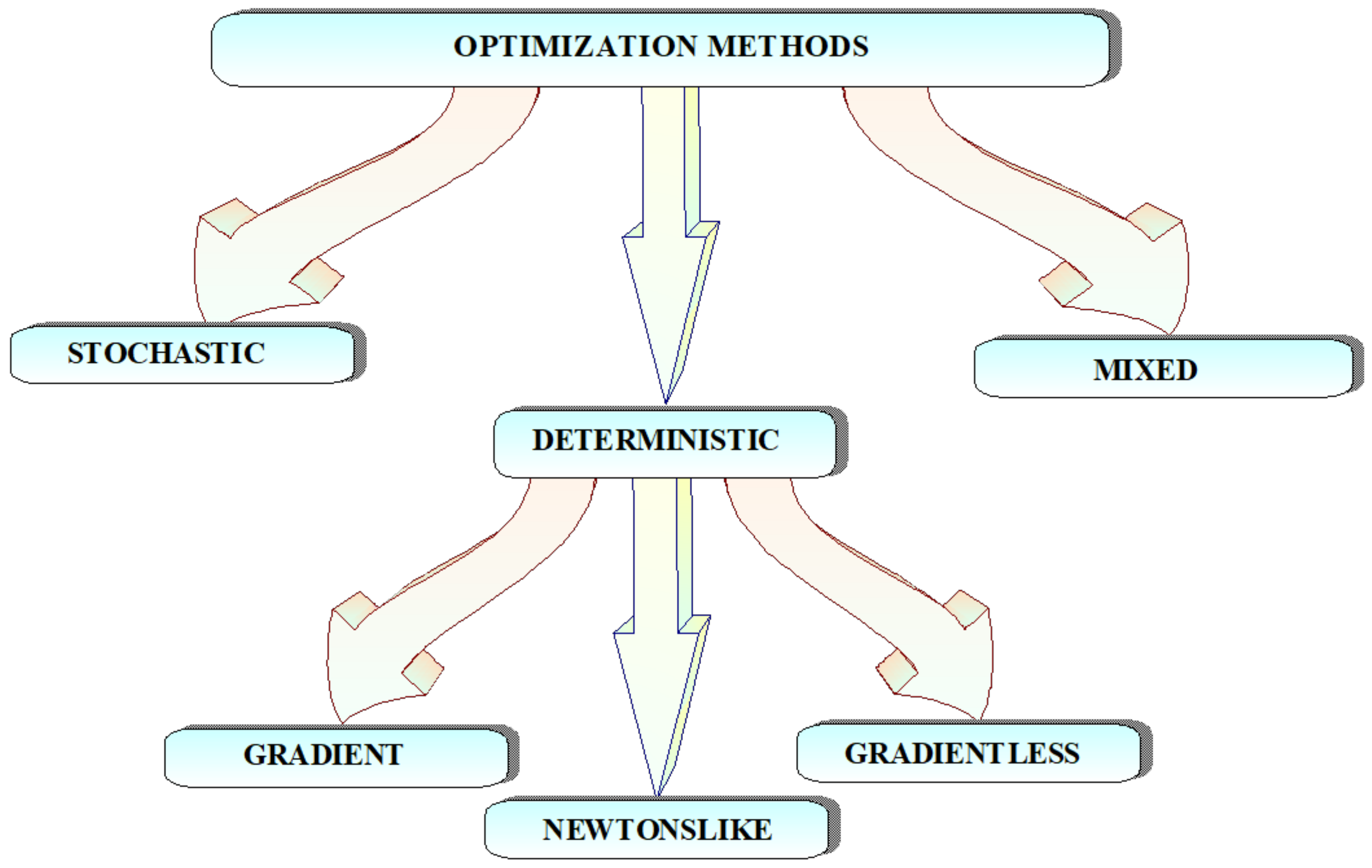
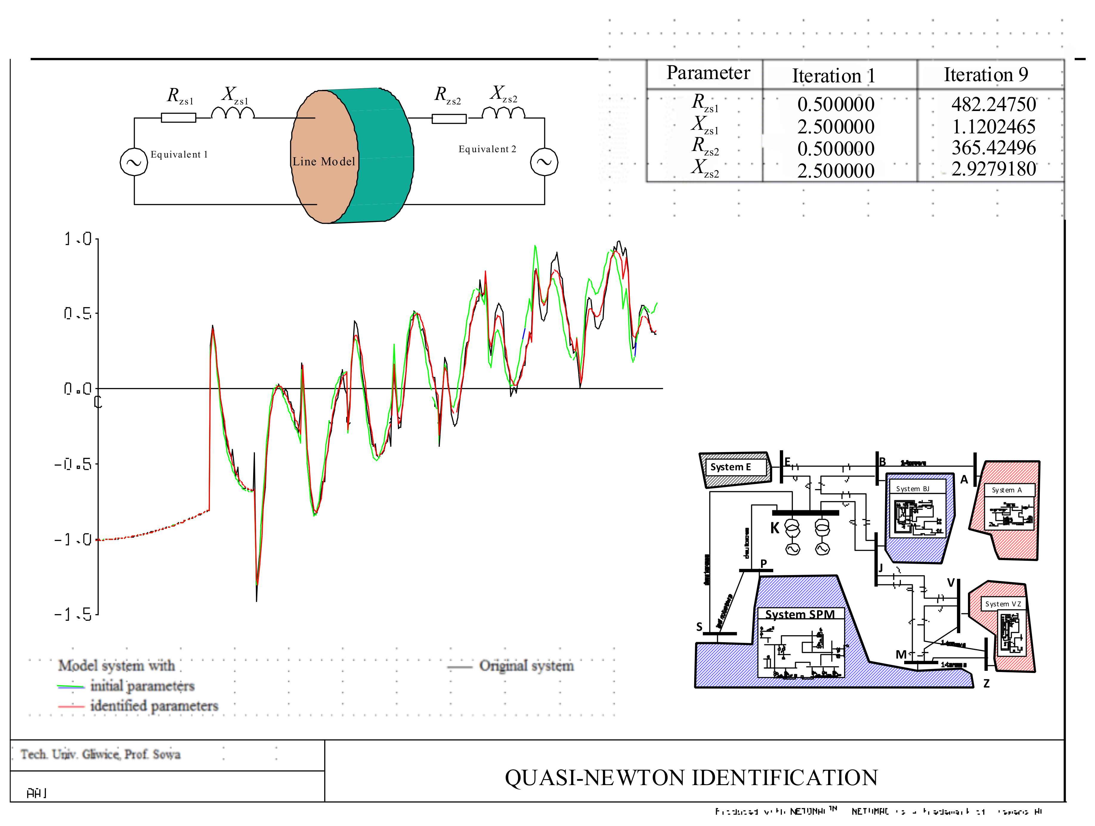
3. Identification of Equivalent System Parameters

3.1. Description of Methods

Regardless of how the structure of the equivalent scheme is determined (in the time or frequency domain or by reducing the original circuit), it is always necessary to identify the parameters included in this structure after its determination.
Choosing the identification method on the basis of literature assessments is very difficult. Most of the methods proposed in the literature were derived for strictly defined problems directly related to simulation programs adapted to this purpose; therefore, their generalization is very limited. In practice, to date, no universal identification method has been developed that would be accurate enough to solve every problem. All of the methods used so far have advantages and disadvantages, while the usefulness criteria are primarily the possibilities of achieving convergence of numerical solutions, the number of iterations, the required computation time and the number of objective functions. Figure 5 shows the conventional division of methods for identifying parameters in specific structures, and, as can be seen, they are optimization methods with all of the consequences of the procedure imposed by these methods.
Figure 6 shows an example of the identification of the parameters of equivalent diagrams carried out using the quasi-Newton method with the use of the NETOMAC program.

3.2. Discussion of the Parameter Identification Method Selection

It is very difficult to find an unambiguous opinion, even in terms of quality, on which of the methods discussed above enables a greater approximation of the waveforms in the original and reduced systems. Comparing the rate of change in parameter values during identification may give a false impression of the speed of a particular method compared to the other two.
Due to the fact that, despite many years of research, no universal substitute system has been found so far that can faithfully reproduce the behavior of the power system during electromagnetic transient states, it seems necessary to distinguish between the processes of searching for a structure and identifying parameters. Tests were carried out in the frequency domain to search for the structure of the equivalent circuit and in the time domain to identify the parameters of the equivalent circuit. The solution that produces the best results is a two-step procedure: first, the structure of the equivalent scheme is determined in the frequency domain, and then the parameters of this structure are identified in the time domain.
In the worst case, knowledge about the power supply system apart from general data, such as the short-circuit power of the system and the topology “in the vicinity” of the tested object. In such a case, one of the propositions of equivalent diagrams must be adopted, and then their parameters must be identified.

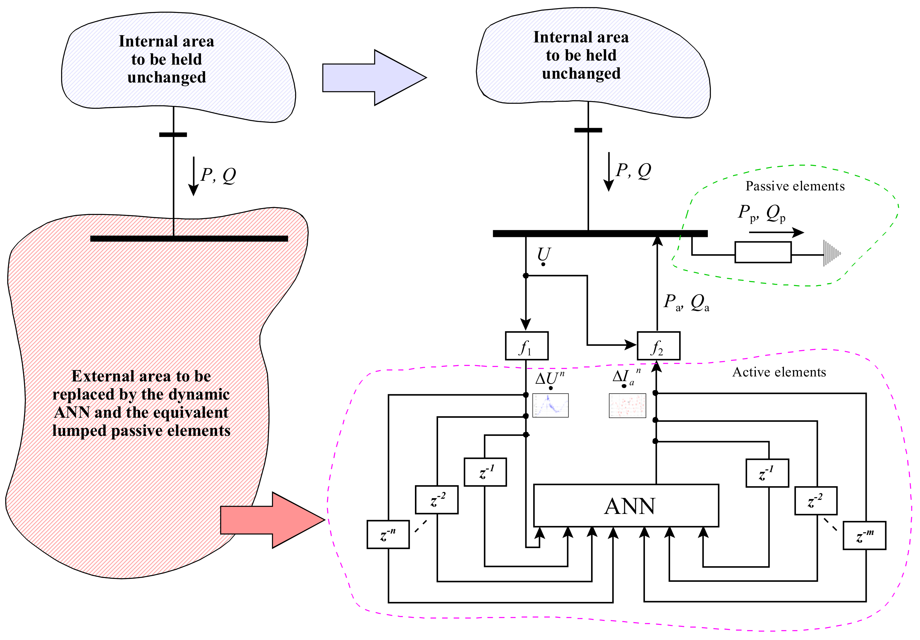
4. Application of ANN to Replace Complex System Structures

To date, few publications have reported attempts to use artificial neural networks (ANNs) to replace extensive and complex power systems [47,49,50,51,52]. The advantages of this approach are manifold: it is not necessary to know the topology of the external system, there are no restrictions on the parameters to be identified, and simulation calculations are not required for the entire external network. In [46], a new approach to the equivalence of a large network was proposed for the study of electromechanical phenomena.
The basis of the proposed method is the replacement of all active elements in a complex external system with dynamic artificial neural networks (ANNs) connected to specific points of the network, to which an equivalent system representing passive loads in the external area is connected at the same time.
The principles of the proposed dynamic equivalencing approach are explained in Figure 7 for one boundary bus [46]. Here, the ANN is an active element of the power system. During a disturbance, the ANN reacts to voltage changes by changing the currents flowing to the boundary nodes. The currents (and not, for example, power or voltage) in the output of the ANN were selected (real and imaginary currents) due to the better separation between the parameters in the input and output. A simple configuration of the system facilitates the implementation of this model within the power system simulation software. Simulation using modern computers is a very quick and simple task, even if the ANN structure consists of many parameters.
It seems that the search for methods to find the optimal structure during electromechanical transient (stability) studies has been well established, as can be seen in many publications [56,57,58].
The success of the search for a universal equivalent for the study of transient electromechanical phenomena may, of course, also be the basis for starting the analysis of the search for such a system for electromagnetic waveforms. However, this is more complex than for the case examined above. As already stated in the previous analysis, when studying electromagnetic phenomena, it is not important to represent the mechanical elements in generators. There is no need to look for coherent generators, but it is important to model lines with frequency-dependent distributed parameters. It therefore seems necessary to extend the area of the internal system to include all adjacent transmission lines, especially if they are connected to the same nodes as the tested object, regardless of whether it is “behind” the measuring point or opposite terminals.
One more significant problem remains: it is not possible to use an ANN if we do not have access to the source code of the software at our disposal. This is due to the fact that the calculations are constantly reverted after each change in the ANN structure. Therefore, if the ANN module is not included in the program for calculating transients, which can cooperate with the actuator during calculations, then such software is useless from this point of view.

5. Summary and Conclusions

The considerations discussed in this monograph allowed several conclusions to be drawn on the fundamental importance for the correctness of the equivalence of power systems for the purposes of simulating electromagnetic phenomena.
Performing a reduction of systems (static or dynamic) is not recommended for the analysis of electromagnetic phenomena. It is assumed that the parameters of the elements are linear and that they are independent of frequency. Moreover, the completely distributed nature of the transmission line parameters is ignored, which is of fundamental importance for the calculation of electromagnetic waveforms.
Methods for searching for equivalents in the frequency domain do not apply to the analysis of transient phenomena during non-simultaneous disturbances, which are most often the primary cause of system failures.
Regardless of the adopted or designated structure of the equivalent diagram, it is necessary to identify the parameters using one of the available optimization methods.
The speed and effectiveness of identification depend on:
  • The complexity of the structure,
  • The number of identified parameters,
  • The number of minimum local objective functions that appear,
  • The time (calculation) step.
If the identification process for a given structure fails (i.e. it is not possible to eliminate the difference between the signals measured in the real system and those calculated in an equivalent system) for the required accuracy of the analysis, the identification process should be carried out for a new, different structure. A change in the starting values and/or the number of measuring points is irrelevant in this case, and before the given structure is finally rejected as unsuitable for a given analysis, identification must be repeated with the changed initial values of the parameters.
Table 1 lists the recommended procedures for searching for substitute patterns for the analysis of electromagnetic transient phenomena.

Author Contributions

D.Z. and P.S. contributed equally to this work and all of its stages and elements. All authors have read and agreed to the published version of the manuscript.

Funding

This research received no external funding.

Institutional Review Board Statement

Not applicable.

Informed Consent Statement

Not applicable.

Data Availability Statement

No new data were created or analyzed in this study. Data sharing is not applicable to this article.

Conflicts of Interest

The authors declare no conflict of interest.

References

  1. Cipra, B.A. An introduction to the Ising model. Am. Math. Mon. 1987, 94, 937–959. [Google Scholar] [CrossRef]
  2. Geeves, S. A modal-coherency technique for deriving dynamic equivalents. IEEE Trans. Power Syst. 1988, 3, 44–51. [Google Scholar] [CrossRef]
  3. Housos, E.C.; Irisarri, G.; Porter, R.M.; Sasson, A.M. Steady State Netwrork Equivalents for Power System Planning Applications. IEEE Trans. Power Appar. Syst. 1980, 6, 2113–2120. [Google Scholar] [CrossRef]
  4. Morched, A.S.; Brandwajn, V. Transmission Network Equivalents for Electromagnetic Transient Studies. IEEE Trans. Power Appar. Syst. 1983, 9, 2984–2994. [Google Scholar] [CrossRef]
  5. Hong, J.H.; Jung, B.T.; Park, J.K.; Kim, S.H.; Ahn, B.S. Transmission Network Equivalents in Time-Domain for Electromagnetic Transients Analysis. In Proceedings of the ICDS ’95, College Station, TX, USA, 5–7 April 1995; pp. 293–298. [Google Scholar]
  6. Silva, R.F. Testing of the Modal Dynamic Equivalents Technique. IEEE Trans. Power Appar. Syst. 1978, PAS-97, 1366–1372. [Google Scholar]
  7. Watson, N.R.; Arrillaga, J. Frequency-dependent AC system equivalents for harmonic and transient converter simulation. IEEE Trans. Power Deliv. 1988, 3, 1196–1203. [Google Scholar] [CrossRef]
  8. Tinney, W.F.; Bright, J.M. Adaptive Reductions for Power Flow Equivalents. IEEE Trans. 1987, PWRS-2, 351–360. [Google Scholar]
  9. Dimo, P. Modal Analysis of Power Systems; Abacus Press: London, UK, 1975. [Google Scholar]
  10. Duran, H.; Arvanitidis, N. Simplification for Area Security Analysis: A New Look at Equivalencing. IEEE Trans. Power Appar. Syst. 1972, 2, 670–679. [Google Scholar] [CrossRef]
  11. Monticelli, A.; Deckmann, S.; Garcia, A.; Stott, B. Real-Time External Equivalents for Static Security Analysis. IEEE Trans. Power Appar. Syst. 1979, 2, 498–508. [Google Scholar] [CrossRef]
  12. Brown, W.T.; Cloues, W.J. Combination Load-Flow and Stability Equivalent for Power System Representation on A-C Network Analyzers. Trans. Am. Inst. Electr. Eng. Part III Power Appar. Syst. 1955, 74, 782–787. [Google Scholar] [CrossRef]
  13. Milano, M.; Srivastava, K. Dynamic REI equivalents for short circuit and transient stability analyses. Electr. Power Syst. Res. 2009, 79, 878–887. [Google Scholar] [CrossRef]
  14. Neto, A.; Rodrigues, A.; Prada, R.; da Silva, M.G. External Equivalent for Electric Power Distribution Networks With Radial Topology. IEEE Trans. Power Syst. 2008, 23, 889–895. [Google Scholar] [CrossRef]
  15. PSS/E 30.1, Program Application Guide. Tech. Rep., Siemens, March 2005. Available online: http://www.pit-us.com (accessed on 20 November 2021).
  16. Machowski, J.; Bialek, J.W.; Bumby, J.R. Power System Dynamics. Stability and Control; John Wiley & Sons: Chichester, NY, USA, 2008. [Google Scholar]
  17. Barquin, J.; Rouco, L.; Vargas, H.R. Generalized Selective Modal Analysis. In Proceedings of the IEEE/PES Winter Meeting: Panel Session on Recent Applications of Linear Analysis, New York, NY, USA, 27–31 January 2002; pp. 1194–1199. [Google Scholar]
  18. Verghese, G.C.; Perez-Arriaga, J.; Schweppe, F.C. Selective Modal Analysis with Applications to Electric Power Systems, Part II: The Dynamic Stability Problem. IEEE Trans. Power Appar. Syst. 1982, 9, 3126–3130. [Google Scholar] [CrossRef]
  19. De Oliveiras, E.M.; De Queirozje, F.; Massaud, A.G. Modal Dynamic Equivalent for Electric Power Systems: Parts 26 I and II. IEEE Trans. Power Syst. 1988, 3, 1723–1737. [Google Scholar] [CrossRef]
  20. Arturi, C.M. Transient Simulation and Analysis of a Three-Phase Five-Limb Step-Up Transformer Following an out-of-Phase Synchronization. IEEE Trans. Power Deliv. 1991, 6, 196–207. [Google Scholar] [CrossRef]
  21. Podmore, R. Identification of Coherent Generators for Dynamic Equivalents. IEEE Trans. Power Appar. Syst. 1978, 4, 1344–1354. [Google Scholar] [CrossRef]
  22. Joo, S.-K.; Liu, C.-C.; Jones, L.; Choe, J.-W. Coherency and Aggregation Techniques Incorporating Rotor and Voltage Dynamics. IEEE Trans. Power Syst. 2004, 19, 1068–1075. [Google Scholar] [CrossRef]
  23. Machowski, J. Dynamic equivalents for transient stability studies of electrical power systems. Int. J. Electr. Power Energy Syst. 1985, 7, 215–224. [Google Scholar] [CrossRef]
  24. Lawler, J.S.; Schlueter, R.A. Computational Algorithms for Compucting Modal-Coherent Dynamic Equivalents. IEEE Trans. Power Appar. Syst. 1982, 5, 1070–1081. [Google Scholar] [CrossRef]
  25. Ward, J.B. Equivalent Circuits For Power Flow Studies. AIEE Trans. 1949, 68, 373–382. [Google Scholar]
  26. Wang, L.; Klein, M.; Yirga, S.; Kundur, P. Dynamic reduction of large power systems for stability studies. IEEE Trans. Power Syst. 1997, 12, 889–895. [Google Scholar] [CrossRef]
  27. Meyer, B.; Stubbe, M. EUROSTAG—A Single Tool for Power System Simulation. Transm. Distrib. Int. 1992, 3, 47–52. [Google Scholar]
  28. DIgSILENT GmbH, DIgSILENT GmbH, Power System Engineering and Software. 2007. Available online: http://digsilent.de (accessed on 20 November 2021).
  29. Kulicke, B. Simulationsprogram Netomac: Differenzen-Leitwertverfahren bei kontinuierlichen und diskontinuierlichen Systemen. Siemens Forschungs–und Entwickl. Ber Bd 1981, 10, 299–302. [Google Scholar]
  30. Hingorani, N.G.; Burbey, M.F. Simulation of AC system impedance in HVDC system studies. IEEE Trans. Power App. Syst. 1970, 89, 820–828. [Google Scholar] [CrossRef]
  31. Clerici, A.; Mario, L. Coordinated use of TNA and Digital Computer for Switching Surge Studies: Transient Equivalent of a Complex Network. IEEE Trans. Power App. Syst. 1970, 8, 1717–1726. [Google Scholar] [CrossRef]
  32. Morched, A.S.; Ottevangers, J.H.; Marti, L. Multi-Port Frequency Dependent Network Equivalents for the EMTP. IEEE Trans. Power Deliv. 1993, 8, 1402–1412. [Google Scholar] [CrossRef]
  33. Semlyen, A.; Iravani, M. Frequency domain modeling of external systems in an Electro-Magnetic Transients Program. IEEE Trans. Power Syst. 1993, 8, 527–533. [Google Scholar] [CrossRef]
  34. Rodriguez, J.M.; Medina, E.; Mahseredjian, J.; Ramirez, A.; Sheshyekani, K.; Kocar, I. Frequency-Domain Fitting Techniques: A Review. IEEE Trans. Power Deliv. 2020, 35, 1102–1110. [Google Scholar] [CrossRef]
  35. Ibrahim, A.I.; Salama, M.M.A. Frequency Dependent Network Equivalent for AC Power System Using the QZ Algorithm. In Proceedings of the 1995 Canadian Conference on Electrical and Computer Engineering, Montreal, QC, Canada, 5–8 September 1995; pp. 56–59. [Google Scholar]
  36. Kizilcay, M. Low-order network equivalents for electromagnetic transients studies. Eur. Trans. Electr. Power 1993, 3, 123–129. [Google Scholar] [CrossRef]
  37. Gustavsen, B.; Semlyen, A. Rational approximation of frequency domain responses by vector fitting. IEEE Trans. Power Deliv. 1999, 14, 1052–1061. [Google Scholar] [CrossRef] [Green Version]
  38. Gavrilovic, M.M.; QueDo, V. An Iterative Pole-Removal Method for Synthesis of Power System Equivalent Networks. IEEE Trans. Power Appar. Syst. 1984, 8, 2065–2070. [Google Scholar] [CrossRef]
  39. Noda, T. Identification of a Multiphase Network Equivalent for Electromagnetic Transient Calculations Using Partitioned Frequency Response. IEEE Trans. Power Deliv. 2005, 20, 1134–1142. [Google Scholar] [CrossRef]
  40. Sowa, P. Search of Optimum Equivalent Representation for Transient Investigations during non-Simultaneous Faults. In Proceedings of the IASTED, International Conference Modeling and Simulation, Pittsburgh, PA, USA, 1–4 May 1998; IASTED/ACTA Press: Calgary, AB, Canada, 1998; pp. 466–470, ISBN 0-88986-252-4. [Google Scholar]
  41. Sowa, P. Optimization of Equivalent Networks for Transient Simulation in H.V. Transmission Systems. In Proceedings of the IASTED, International Conference—Modeling, Simulation and Optimization, Gold Coast, Australia, 6–9 May 1996; pp. 205–242. [Google Scholar]
  42. Todd, S.; Wood, A.R.; Bodger, P.S.; Smith, B.C. Rational functions as frequency dependent equivalents for transient studies. In Proceedings of the IW7 International Conference on Power Systems Transients, Seattle, WA, USA, 22–26 June 1997; pp. 137–144. [Google Scholar]
  43. Kulicke, B.; Hinrichs, H.J. Parameteridentifikation und Ordnungsreduktion mit Hilfe des Simulationsprogramms Netomac. Etz-Archiv 1988, 10, 207–213. [Google Scholar]
  44. Abur, A.; Singh, H. Time domain modeling of external systems for electromagnetic transients programs. IEEE Trans. Power Syst. 1993, 8, 671–679. [Google Scholar] [CrossRef]
  45. Boaventura, W.; Semlyen, A.; Iravani, M.; Lopes, A. Robust Sparse Network Equivalent for Large Systems: Part I—Methodology. IEEE Trans. Power Syst. 2004, 19, 157–163. [Google Scholar] [CrossRef]
  46. Azmy, A.; Erlich, I.; Sowa, P. Artificial neural network-based dynamic equivalents for distribution systems containing active sources. IEE Proc. Gener. Transm. Distrib. 2004, 151, 681–688. [Google Scholar] [CrossRef]
  47. Rahim, A.; Al-Ramadhan, A. Dynamic equivalent of external power system and its parameter estimation through artificial neural networks. Int. J. Electr. Power Energy Syst. 2002, 24, 113–120. [Google Scholar] [CrossRef]
  48. Sowa, P. Comparison of results of optimization by searching of equivalent system. In Proceedings of the 2008 40th North American Power Symposium, Calgary, AB, Canada, 28–30 September 2008; Institute of Electrical and Electronics Engineers (IEEE): Piscataway, NJ, USA, 2008; p. 4. [Google Scholar]
  49. Stankovic, A.; Saric, A. Transient Power System Analysis With Measurement-Based Gray Box and Hybrid Dynamic Equivalents. IEEE Trans. Power Syst. 2004, 19, 455–462. [Google Scholar] [CrossRef]
  50. Stankovicc, A.; Saric, A.; Milosevic, M. Identification of nonparametric dynamic power system equivalents with artificial neural networks. IEEE Trans. Power Syst. 2003, 18, 1478–1486. [Google Scholar] [CrossRef]
  51. Tuglie, E.D.; Guida, L.; Torelli, F.; Lucarella, D.; Pozzi, M.; Vimercati, G. Identification of Dynamic Voltage-Current Power System Equivalents through Artificial Neural Networks. In Proceedings of the Bulk Power System Dynamics and Control, VI, Cortina d’Ampezzo, Italy, 22–27 August 2004; pp. 220–226. [Google Scholar]
  52. Sowa, P. Representation of power system for electromagnetic transient calculation. Int. J. Electr. Power Energy Syst. Eng. 2008, 1, 152–155. [Google Scholar]
  53. Mahseredjian, J.; Dinavahi, V.; Martinez, J.A. Simulation Tools for Electromagnetic Transients in Power Systems: Overview and Challenges. IEEE Trans. Power Deliv. 2009, 24, 1657–1669. [Google Scholar] [CrossRef]
  54. Mahseredjian, J. Computation of power system transients: Overview and challenges. In Proceedings of the 2007 IEEE Power Engineering Society General Meeting, Tampa, FL, USA, 24–28 June 2007; p. 7. [Google Scholar] [CrossRef]
  55. Cervantes, M.; Ametani, A.; Martin, C.; Kocar, I.; Montenegro, A.; Goldsworthy, D.; Tobin, T.; Mahseredjian, J.; Ramos, R.; Marti, J.R.; et al. Simulation of Switching Overvoltages and Validation With Field Tests. IEEE Trans. Power Deliv. 2018, 33, 2884–2893. [Google Scholar] [CrossRef]
  56. Pavella, M. Power system transient stability assessment—Traditional vs modern methods. Control. Eng. Pract. 1998, 6, 1233–1246. [Google Scholar] [CrossRef]
  57. Zhang, Y.; Wehenkel, L.; Pavella, M. SIME: A Comprehensive Approach to Fast Transient Stability Assessment. IEEJ Trans. Power Energy 1998, 118, 127–132. [Google Scholar] [CrossRef] [Green Version]
  58. Pavella, M. Generalized one-machine equivalents in transient stability studies. IEEE Power Eng. Rev. 1998, 18, 50–52. [Google Scholar] [CrossRef]
Figure 1. Investigated object supplied by (a) simple system, (b) double separated system, (c) double connected system.
Energies 15 01396 g001
Figure 2. Review of methods for searching for equivalents.
Energies 15 01396 g002
Figure 3. Transient voltages during non-simultaneous three-phase to ground fault.
Energies 15 01396 g003
Figure 4. Frequency response for different fault conditions.
Energies 15 01396 g004
Figure 5. Optimization methods for parameter identification.
Energies 15 01396 g005
Figure 6. Quasi-Newton parameter identification.
Energies 15 01396 g006
Figure 7. Principles of the proposed dynamic equivalencing approach.
Energies 15 01396 g007
Table 1. Recommendations for equivalents when testing electromagnetic transients.
Action
Structure Search in the FieldParameter IdentificationReductionInitial Struture
Knowledge of the
Structure of the Original System
YESSingle-sided power or unconnected systemss *FrequencyNecessaryStaticUnnecessary
w **TimeNot recommendedUnnecessary
Connecteds *FrequencyDynamicUnnecessary
w **TimeNot recommendedUnnecessary
NOMeasurement resultsUnnecessaryUnnecessaryANN
Short-circuit power only
(number of lines known)
UnnecessaryUnnecessaryANN
* s—only linear elements with frequency-independent lumped parameters are available. ** w—all layout elements available.
Publisher’s Note: MDPI stays neutral with regard to jurisdictional claims in published maps and institutional affiliations.

