Article

Optimization of Heat Exchange Plate Geometry by Modeling Physical Processes Using CAD

by
Igor Korobiichuk
1,*,
Viktorij Mel’nick
2,
Vladyslav Shybetskyi
2,
Sergii Kostyk
2 and
Myroslava Kalinina
2
1
Warsaw University of Technology, Institute of Automatic Control and Robotics, 02-525 Warsaw, Poland
2
National Technical University of Ukraine “Igor Sikorsky Kyiv Polytechnic Institute”, 03056 Kyiv, Ukraine
*
Author to whom correspondence should be addressed.
Energies 2022, 15(4), 1430; https://doi.org/10.3390/en15041430
Submission received: 6 January 2022 / Revised: 9 February 2022 / Accepted: 11 February 2022 / Published: 16 February 2022

Abstract

:
This article presents the possibility of evaluating the efficiency of the heat exchange element with a special stamping plate, which is based on the results of computer simulation. The method is based on a comparative analysis of convective heat transfer models implemented in ANSYS using a k-ε turbulence model. To conduct the study, 3D models of three different types of cavity geometry formed between two heat exchange plates (flat plate, chevron plate, and plate with conical stampings) were built. Simulation was performed by finite element analysis in ANSYS for channels formed by the three types of plates, one of which is a new configuration. The results of hydrodynamic and heat exchange parameters allowed for establishing the efficiency of convective heat exchange for plates of known structures and to compare them with the proposed one. It was found that the plates with conical stamping form the smallest channels through which the fluid moves. The velocity of the coolant is uniform throughout the cross section of the channel and equal to 0.294 m/s; the value of the heat transfer coefficient is the largest of the three models and is 5339 W/(m K), while the pressure drop is 1060 Pa. Taking into account the simulation results, the best heat transfer parameters were shown by the channel formed by plates with conical stamping and the highest pressure drop. To increase the efficiency, indicated by the ratio of heat transfer coefficients to hydraulic resistance, the geometry of the plate with conical stamping was optimized. As a result of optimization, it was found that the optimal geometric parameters of the heat exchange plate with conical stamping were achieved at a 55° inclination angle and 1.5 mm height for the cone. The results of this study can be used in the design of heat exchange elements of new structures with optimal parameters for highly efficient heating of liquid coolants.

1. Introduction

Plate heat exchangers are currently among the most widespread in the industry. This is due to several advantages that they have relative to their counterparts, where tubes are used as heat exchangers [1,2]. The main advantage of plate heat exchangers is their compactness with a sufficiently large heat exchange surface under moderate hydraulic resistance [3,4].
However, along with several advantages, there is a certain limitation, which is connected with the need to corrugate heat exchange plates [5,6]. This is necessary to minimize deposits on plate surfaces and to create local flow turbulizations, which increase heat transfer coefficients [7,8,9,10,11]. The intensity of heat transfer directly depends on the geometry of the corrugation on the surface of the plates. Jiang et al. [12] investigated the effect of geometric dimensions of the capsule-type plate heat exchanger on the efficiency of the heat exchanger. They found that the number of longitudinal vortices decreases and the size of the longitudinal vortices increases with increasing Re or decreasing length-to-width ratio of the capsule. In addition, the Nusselt number and friction factor decrease with increasing length-to-width ratio of the capsule. Savvin et al. [13] compared the efficiency of shell-and-tube and plate heat exchangers on an experimental stand “independent heating system of a residential building” and drew conclusions about the advantages of the plate heat exchanger. Arsenyeva et al. [14] conducted numerical modeling of the plate heat exchanger and compared the results with experimental data. The authors established that for a specified pressure drop, temperature program, and heat load, the geometric parameters of the plate and its corrugations, which are able to make PHE with minimal heat transfer area, can be found.
Selection of the optimal geometry, in which the increase in heat transfer coefficients is achieved, is usually carried out experimentally, and by using the theory of similarity the criterion equations that allow the calculation of heat transfer parameters are obtained [15,16,17].
However, in terms of economic costs, this is a very costly solution, so this optimization problem benefits from the use computer modeling and CAD (computer-aided design) [18,19]. Rauber et al. [20] used hybrid numerical–experimental analysis to obtain the thermal and hydraulic performances to determine the efficiency of plate-finned heat exchangers. They found that larger holes in the fins increase the efficiency of the heat exchanger. The simulation was performed using ANSYS-Fluent® software. To validate the results, a comparison of the Nusselt number obtained in the simulation with data from the literature was used. Payambarpoura et al. [21,22] studied the effect of wetness level of the fin surface on heat and mass transfer by using 2D modeling. The results obtained show that the increase in surface wetness leads to a decrease in the efficiency of the heat exchanger. The authors note that the use of 3D simulations can be a way to increase the accuracy of the evaluations and the efficiency of the heat exchanger. Aljubaili et al. [23] also used numerical methods to solve the problems of flow around ribbed surfaces, namely the spectral element code, Nek5000. Baran et al. [24] used a numerical method for acoustically driven streaming flow for different frequencies of the acoustic wave and different temperature gradients between hot and cold surfaces. All of these studies confirm the feasibility of choosing numerical simulation methods for the study of hydrodynamics and heat transfer in heat exchangers. Lisowski et al. [25] used numerical analysis to find the influence of the number of fins and frost accumulated within the fin surface on the heat transferred through the aluminum finned tubes of ambient air vaporizers. For this purpose, the finite element thermal analysis within ANSYS software was used.
The classical technique of determining the coefficients of convective heat transfer between the coolant and the surface consists of the following stages [3]:
  • Determination of average useful temperature difference of heat transfer fluids and surfaces.
  • Determination of the mode of movement of heat transfer fluids in the channel by using Reynolds number:
    R e = w d ν = ρ w d μ ,
    where
    • w —Linear speed of the coolant in the channel (m/s);
    • d —Determining size of the channel through which the coolant moves (m);
    • ν —Kinematic viscosity of the coolant (m/s2);
    • ρ —Density of the coolant (kg/m3);
    • μ —Dynamic viscosity of the coolant (Pa/s).
  • On the basis of the theory of similarity, we select the criterion Nusselt equation for a certain mode of motion of the coolant in the channel between corrugated plates [3]:
    N u = C R e n P r m ( P r f P r w ) 0.25 ,
    where
    • Nu—Nusselt number:
    N u = α d λ ,
    • Re—Reynolds number (1);
    • Pr—Prandtl number:
    P r = μ c λ ,
    • Prf, Prw—Prandtl number at fluid flow temperature and at plate wall temperature, respectively;
    • C, n, m—Coefficients selected depending on the mode of motion of the coolant and the surface of the plate;
    • α—Heat transfer coefficient (W/m2 K);
    • c—Specific heat capacity of the coolant (J/kg K);
    • λ—Thermal conductivity coefficient (W/m K).
  • The value of the Nusselt number from Equation (2) is substituted in (3) to determine the heat transfer coefficient between the coolant and the plate:
α = N u λ d ,
Thus, the efficiency of the heat exchange surface can be expressed due to the value of the heat transfer coefficient. The higher the value, the higher the heat flow and the higher the heat transfer efficiency. It was proved via experiment that the change in the geometry of the corrugated plate of the heat exchanger affects the change in the heat transfer coefficient, due to local turbulization of the flow and the destruction of laminar layers. The creation and development of a new geometry of corrugated heat exchange surfaces to ensure high heat transfer coefficients is an actual task.
The scientific novelty of this study is the possibility of studying convective heat transfer in channels of complex shape using the finite element method. The research presented in this article allows for evaluating qualitatively and quantitatively the efficiency of the new design of the heat exchange plate with conical stamping and its further optimization through modeling.
In this article, an example is proposed for a new geometry of a corrugated heat exchange plate, which is used to demonstrate the possibility of evaluating its thermal potential at the stage of computer model development, without the need to create and research experimentally a manufactured plate. This approach is already described in articles that are devoted to the simulation of physical processes in the equipment [26,27].
To achieve this goal, it is necessary to complete the following tasks:
  • Construct the geometry of the internal cavity of the heat exchanger;
  • Build a computer model of the process of the convective flow between plates for different designs of the surfaces;
  • Analyze the influence of the geometry of the heat plates on the efficiency of heat transfer.

2. Materials and Methods

This research was implemented in the universal software system of finite element analysis ANSYS in the Fluid Flow CFX module.
The simulation was carried out to analyze the influence of plate geometry on heat transfer coefficient and the selection of optimal parameters. Optimization and efficiency testing is based on the comparative analysis of computer models of different heat exchange plate designs:
  • Simulation of heat exchange when moving a liquid in a flat wall channel.
  • Simulation of heat exchange during fluid movement in the channel formed by chevron plates.
  • Simulation of heat exchange when moving fluid in a channel formed by plates with conical stamping.
  • Optimization of heat exchange plate design with conical stamping.
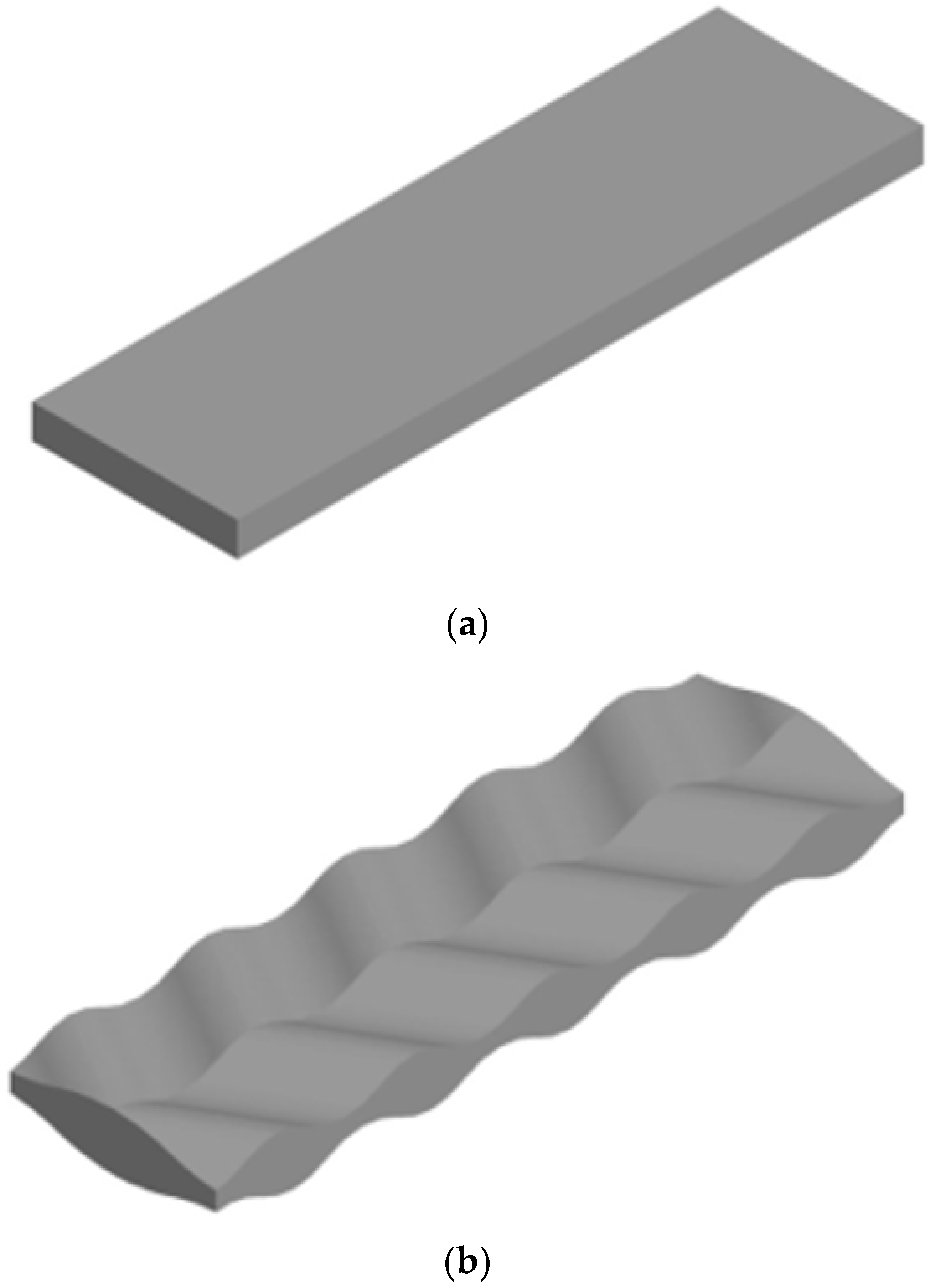
For research, 3D models were built for three different types of cavity geometry formed between two adjacent plates (Figure 1):
  • Flat heat plate;
  • Chevron plate;
  • Plate with conical stamping.
The dimensions of the design areas for each model are indicated in the example of geometry with flat plates (Figure 2): the parameters are height H = 5 mm; length L = 100 mm; and width D = 30 mm.
Characteristic dimensions for chevron heat exchange plate (Figure 3): the parameters are stamping step t = 21 mm; rounding radius R = 10 mm; smallest distance between the plates h = 2.5 mm; and height H = 5 mm.
To determine the influence of parameters of heat exchange plate geometry with conical stamps, modeling is carried out for the following parameters (Figure 4): larger cone diameter d = 5 mm; cone height h acceptance values 2.5, 2, 1.5, and 1 mm; stamping step t = 6 mm; stamping placed on the vertices of regular triangles; tilt angle of the twisted cone α varies in the range 50–65°, with a 5° step; and height H = 5 mm.
Material used as a coolant is «Water» built-in library with the following thermophysical parameters at temperature t = 20 °C [28]: density ρ = 998.2 kg/m3; kinematic viscosity coefficient ν = 0.001 m2/s; specific heat capacity c = 4183 J/kg K; and thermal conductivity coefficient λ = 0.599 W/m K.
To implement the finite element method, the design areas are divided into elements of the main determining dimensions using the module Mesh (Figure 5). The Grid Setup Options that are applied follow [29,30]:
  • Mesh consists of tetrahedra (function Method control: Tetrahedrons);
  • When constructing a grid, the function is included «Use Adaptive Sizing» setting the parameter «Resolution» equal to 7.
The average number of elements in the resulting grid is equal to 69,000 and the number of nodes is 14,500.
Boundary conditions of the process:
  • Water enters through the front end with speed w = 0.5 m/s and temperature t = 20 °C, boundary condition «Inlet» (Figure 6, position 1);
  • The water output is located on the opposite side of the volume, boundary condition «Outlet», pressure at the exit of the volume P = 105 Pa (Figure 6, position 2);
  • For the side ends, the border type is set to «Symmetry» to reduce the resources and time for modeling (Figure 6, position 3);
  • The upper and lower surfaces of the volume model contact with heat exchange plates having temperature tw = 60 °C and boundary condition «Wall» (Figure 6, position 4).
Modeling is carried out for a stationary problem. An option is activated to simulate heat exchange «Total Energy» in domain settings [26,31,32].

3. Validation

Validation of solutions is a very important step in FEM simulation research. In order to validate the results, it is necessary to compare the present model simulation with a definite and correct result. In this study, an analytical solution for a flat plate is used to ensure numerical accuracy. The analytical solution is made by using empiric formulas (1)–(5) with the same parameters as used in 3D modeling. Thus, the heat transfer coefficient for the flat plate is 3193 W/m2 K for modeling and 3279 W/m2 K (Re = 5000, Nu = 54.7) for the analytical solution. The maximum error between the numerical results and the analytical solution is about 3%.
Mesh independence was examined to ensure the reliability of the simulation results. For the chevron plate and plate with conical stamping, a series of research tests were performed to determine the influence of mesh quality on modeling accuracy. A sizing resolution from 1 to 7 was used to create the mesh and calculate the heat transfer coefficient. The number of elements in the chevron plate for sizing resolution 6 was 52,613 and the average heat transfer coefficient was 3340 W/(m2 K); for sizing resolution 7, the number of elements was 93,748 and the average heat transfer coefficient was 3281 W/(m2 K). The difference of the average heat transfer coefficient between the results for the 52,613 and 93,748 element mesh systems was less than 2%. A further increase in the number of mesh elements to 189,654, performed by reducing the minimum element size, led to a change in the heat transfer coefficient of less than 0.5%, although the simulation time increased by more than 3.5 times. This indicated the inexpediency of further increasing the number of elements. Therefore, the sizing resolution 6 was validated and employed in this research. The same level of accuracy was obtained for the plate with conical stamping.

4. Results and Discussion

The influence of plate geometry on heat transfer coefficient was investigated. Figure 7 presents the temperature distribution circuits along the heat exchange plate for the three types of plate geometry.
The temperature of the coolant along the flow varies evenly. For flat geometry plates and chevron plates, the temperature in the middle of the flow at the inlet and outlet are almost unchanged. When using plates with conical stamps, the temperature in the middle of the outlet flow increases by 8 °C.
Figure 8 presents trajectories of fluid particles along the plate for the three types of plate geometry.
Fluids between plates move along clearly defined trajectories. The movement of the coolant between the flat plates is stationary and is mostly laminar, and the trajectory is almost straight. For this plate, the highest flow rate is almost two times less than the maximum speeds for other plates, and there are no stagnation zones because the movement of particles does not interfere with the flow. In this case, the liquid almost does not become warm.
For the chevron plate, the trajectory has the form of large waves with minor transition zones. The speed of the coolant in this case decreases and there is a chance of a stagnant zone due to a change in the cross section of the channel. Here, as in the previous case, the liquid in the middle of the stream almost does not become warm.
For the plate with conical stampings, the particle motion trajectory is small waves with significant areas of turbulent flow. The speed of the coolant is much less, as the plates form much smaller channels for fluid movement than in the previous cases. However, the liquid in this case warms more intensively in the middle of the stream. This can be explained by observing that longitudinal vortices are formed, which increase heat transfer [12]. The structure of the vortex system is strongly influenced by the channel geometry and Reynolds number.
Figure 9 presents vectors of fluid velocity in the middle section of the volume. The speed of the coolant depends on the configuration of the channel through which it moves. In the case of flat plates, the geometry of the channel is the simplest; the speed is the same throughout the length and takes the value w = 0.511 m/s. In the channel formed by chevron plates, the maximum speed w = 1.127 m/s. Owing to changes in the cross section of the channel, the speed is distributed unevenly and varies in different areas. Plates with conical stampings form the smallest channels through which the liquid moves. The speed of the coolant is uniform throughout the cross section of the channel and takes the value w = 0.294 m/s.
Figure 10 shows contours of the heat transfer coefficient from the wall to the fluid flow.
The highest value heat transfer coefficient takes for the case of plates with conical stamping is α = 7988 W/m2 K. For flat plates, it is α = 3193 W/m2 K. For chevron plates, the largest coefficient value is α = 6299 W/m2 K. The data obtained show that the more complex the configuration of the channel, the higher the heat transfer coefficient. This is due to the fact that the characteristic of turbulent motion is the pulsation of pressures and speeds. The complex configuration of the plate stamping forms a channel of variable cross section in which the fluid constantly changes the module and direction of the velocity vector, in accordance with Bernoulli’s law; this affects the local pressure change. The data obtained confirm the fact that during the transition from laminar to turbulent flow there is an increase in heat transfer coefficients. The heat transfer coefficients are large at the windward sides of the stamping, where the vortices generate and at the bottom of stampings. Furthermore, at the backside of the conical stamping, the heat transfer coefficient is low owing to flow stagnation and separation of the wake region. The same trends are shown by Jiang et al. [12].
Average values of the heat transfer coefficient from the wall to the liquid follow: α = 2472 W/m2 K for the flat heat exchange plate; α = 3340 W/m2 K for the chevron heat exchange plate; and α = 5339 W/m2 K for the heat exchange plate with conical stamping.
The results of the research were combined into one module, “Results”. This allows for displaying temperature changes and pressure drop for each model, as shown in shared graphs (Figure 11 and Figure 12).
The graphs in Figure 11 show that the highest temperature was achieved in the heat exchange plate with conical stamping, t = 27.8 °C. Temperatures in the two other cases change almost equally: t = 22.2 °C for flat heat exchange plate and t = 22.4 °C for chevron heat exchange plate.
From the graph in Figure 12, note the drop of pressure when fluid is moving along the plate, which is expressed in a change in pressure. In the flat heat exchange plate and the plate with conical stamps, the pressure changes linearly. In the chevron heat exchange plate, pressure pulsations occur, and the graph indicates vibration. This results from the change in the transverse area between the heat exchange plates.
The pressure drop of the coolant is determined as the pressure difference between the inlet pressure and the outlet pressure: P = 40 Pa for the flat heat exchange plate; P = 250 Pa for the chevron heat exchange plate; and P = 1060 Pa for the heat exchange plate with conical stamps. The data obtained show that the largest pressure drop occurs for the plate with conical stamps, P = 1060 Pa; for the flat heat exchange plate it is the smallest, P = 40 Pa; and for the chevron plate it is P = 250 Pa.
By analyzing the results, it can be argued that the channel formed by the flat plates gives the worst heat transfer coefficients, but the value of the hydraulic resistance of this channel is the smallest of the three. In turn, the channel formed from plates with conical stamps gives the highest value of heat transfer coefficients, but the greatest drop of pressure is observed. In terms of maximum design efficiency, it is worth highlighting the chevron structure of the plates, since high values of heat transfer coefficients are observed in the channel without high hydraulic support. However, in the case of plates with conical stamps, the largest heat transfer coefficients are observed and the highest fluid temperature is achieved. Therefore, it is necessary to consider for each case which option is the most effective. If an important parameter is the minimum pressure drop on the movement of fluid in the channel, then it is rational to choose chevron plates. In the case when it is necessary to carry out rapid heating in a limited volume, then choose the plate with conical stamps as the correct configuration.
Thus, the proposed technique for evaluating the efficiency of the heat exchange plate of a new design by conducting computer modeling can be used to optimize new structures of heat transfer plates, without the need for their manufacture and experiment. The simulation allows for estimation of not only the hydromechanical characteristics, but also to obtain average values of heat transfer coefficients, which are usually obtained during an actual experiment. Thus, it is possible to calculate the heat flow for the whole heat exchanger, at the stage of designing its heat exchange elements. The proposed technique allows for optimizing the design and provides rational parameters, until the creation of a pilot installation, which certainly affects the minimization of time, resources, and funds. Next, described below are the results of optimization and selection of most favorable geometric parameters for the heat exchange plate with conical stamps.
The aim of optimization is to establish the stamping parameters of the plates with conical stamping, which is the design that provides the maximum value of the heat transfer coefficient and a large temperature difference at low values of pressure drop. To establish the optimal parameters of stamping, the height of the cone is changed from 1 to 2.5 mm and the angle of inclination of the cone from 50° to 65°. Initially, calculations were performed to establish the optimal value of the angle, after which the height of the cone was optimized.
The optimization procedure is started by using common settings for modeling (Figure 13). Then the first value of the angle of inclination is set and calculation of heat transfer coefficient, pressure drop, and temperature is made according to the flowchart. Because of changing cross section of the channel, where the fluid is flowing, it is necessary to have not only the value of variables, but the chart of their distribution. Then after increasing the inclination angles and calculating all variables, the comparative analysis is made. Based on the results, an optimal angle of inclination is chosen. A further step is to use the same algorithm and determine how changes of cone height can affect efficiency of the heat plate. By changing height from the smallest to the largest value, the set of variables is obtained. Finally, results are compared and the optimal cone height is found.
Modeling for cone height values was carried out for 2.5, 2, 1.5, and 1 mm, and the angle of inclination of the cone created was 50°, 55°, 60°, and 65°.
The graphs in Figure 14 show changes in temperature of the coolant when moving the liquid in the channel between the plates for different inclination angles of the cone created.
Graphs show that the highest temperature (28.7 °C) can be achieved at the angle of inclination of the cone tilt equal to 65°. The slightest temperature change (25.3 °C) is observed at an angle 50°. Temperatures for selected angles are presented in Table 1. This trend can be explained by the angle of attack, in the angle between the direction of the velocity vector of the flow, and the characteristic longitudinal direction. In this case, increasing the angle of inclination of the cone tilt leads to decreasing angle of attack. Thermodynamic characteristics decrease with increasing angle of attack, which was confirmed by Deeb [33].
Figure 15 presents graphs of pressure drop when the liquid in the channel is moving between the plates, given for different inclination angles of the cone created.
The pressure drop value for the different angles of the tilt cone is equal: for the angle 50°, P1 = 1050 Pa; for angle 55°, P2 = 870 Pa; for angle 60°, P3 = 950 Pa; and for angle 65°, P4 = 1320 Pa. From the data obtained, it can be seen that the largest pressure drop occurs when the angle of inclination for the concave is equal to 65°.
Having analyzed data from the graphs (Figure 14 and Figure 15), it can be seen that the optimal angle of inclination of the tilt cone for a plate with a conical stamp is the angle 55°.
The average values of the heat transfer coefficient from the wall to the liquid are shown in Table 2.
The table shows that the highest value of the heat transfer coefficient can be obtained at an angle 55° and the lowest value at 50°.
Figure 16 presents graphs of temperature changes of moving coolant in the channel between the plates with different values of cone height.
Graphs show that the highest temperature (26 °C) can be achieved at a cone height equal to 2.5 mm. The slightest temperature change (22.8 °C) is observed at a height equal to 1 mm. The temperature difference for the values of the height of the cone at 2 and 2.5 mm is only 0.2 °C, which indicates the inefficiency of further increasing height.
Temperature values for selected cone heights are presented in the Table 3.
Figure 17 presents pressure drop graphs for fluid moving in the channel between the plates for different cone heights.
The pressure drop values for different cone height values are equal: for height 1 mm, P1 = 250 Pa; for height 1.5 mm, P2 = 480 Pa; for height 2 mm, P3 = 630 Pa; and for height 2.5 mm, P1 = 680 Pa. From the data obtained, it can be seen that the largest pressure drop occurs when the height of the cone is 2.5 mm.
After analyzing data from Figure 15 and Figure 16, it can be seen that the optimum cone height for a plate with conical stamps is 1.5 mm.
Average values of heat transfer coefficient from the wall to the liquid when changing the height of the stamping are shown in Table 4.
The table shows that the highest value of the heat transfer coefficient can be obtained at height 2.5 mm, and the least when the height is 1 mm.
As a result of optimization, it is found that optimal geometric parameters of the heat exchange plate with conical stamps are achieved when the angle of inclination of the tilting cone is 55° and the cone height is 1.5 mm.

5. Conclusions

The research provides the opportunity to make the following conclusions:
  • For each case, the change in temperature and pressure in the middle flow between the plates and the average values of heat transfer coefficients from the wall to the liquid were determined. Temperature, pressure drop, and heat transfer coefficients follow for three types of stamping: flat heat exchange plate—t = 22.2 °C, P = 40 Pa, α = 2472 W/m2; chevron heat exchange plate—t = 22.4 °C, P = 250 Pa, α = 3340 W/m2; and plate with conical stamps—t = 27.8 °C, P = 1060 Pa, α = 5339 W/m2. After analyzing the data, a heat exchange plate with conical stamps was selected, which has the highest parameters of heat transfer and temperature difference.
  • The peculiarities of the process of convective heat transfer in the channel formed by plates with conical stamping are established. The trajectory of the particles is small waves with significant areas of flow turbulence. The velocity of the coolant is much lower because the plates form much smaller channels for fluid movement than in the case of other plates. However, the liquid in this case is heated more intensely in the middle of the stream. Stagnant zones occur closer to the coolant outlet.
  • The more complex the configuration of the channel, the greater the heat transfer coefficient. This is due to the fact that the characteristic of turbulent motion is the pulsation of pressures and velocities. The complex configuration of the stamping plates forms a channel of variable cross section, in which the fluid constantly changes the modulus and direction of the velocity vector and, according to Bernoulli’s law, it affects the local pressure change.
  • Optimization of heat exchange plate design with conical stamps was carried out for the following parameters: the angle of inclination of the tilt changed in the range from 50° to 65° with a 5° step and the height of the stamping ranged from 1 to 2.5 mm with a 0.5 mm step. A heat exchange plate with conical stamps with a cone height of equal to 1.5 mm and an angle of inclination of the tilting cone of 55° was selected.

Author Contributions

Conceptualization, I.K., V.M., V.S., S.K. and M.K.; methodology, V.M. and V.S.; software, V.S., S.K. and M.K.; validation, V.M. and V.S.; formal analysis, I.K., V.M. and V.S.; investigation, I.K., V.M., V.S., S.K. and M.K.; resources, I.K., V.M. and V.S.; data curation, V.S., S.K. and M.K.; writing—original draft preparation, V.S., S.K. and M.K.; writing—review and editing, I.K. and V.S.; visualization, V.S.; supervision, I.K.; project administration, I.K.; funding acquisition, I.K. All authors have read and agreed to the published version of the manuscript.

Funding

This project was funded by a research grant from the Scientific Council of the Discipline of Automation, Electronics, and Electrical Engineering of Warsaw University of Technology, and partially funded by the POB Research Center for Artificial Intelligence and Robotics of Warsaw University of Technology within the Excellence Initiative Program—Research University (ID-UB).

Conflicts of Interest

The authors declare no conflict of interest.

References

  1. Bart, H.-J.; Scholl, S. Innovative Heat Exchangers; Springer: Berlin/Heidelberg, Germany, 2018; pp. 1–394. [Google Scholar] [CrossRef]
  2. Popov, D.; Fikiin, K.; Stankov, B.; Alvarez, G.; Youbi-Idrissi, M.; Damas, A.; Evans, J.; Brown, T. Cryogenic heat exchangers for process cooling and renewable energy storage: A review. Appl. Therm. Eng. 2019, 153, 275–290. [Google Scholar] [CrossRef]
  3. Ioffe, I. Design of Processes and Apparatuses of Chemical Technology; Chemistry: Leningrad, Russia, 1991. [Google Scholar]
  4. Datta, N.; Zhuang, Z.; Qin, W. Experimental study of a liquid desiccant regeneration system: Performance analysis for high feed concentrations. Clean Technol. Environ. Policy 2020, 22, 1255–1267. [Google Scholar] [CrossRef]
  5. Prun, O.E.; Garyaev, A.B. Method for Optimization of Heat-Exchange Units Working in Heat Recovery Systems. Therm. Eng. 2020, 67, 560–566. [Google Scholar] [CrossRef]
  6. Lin, W.; Ling, Z.; Fang, X.; Zhang, Z. Research progress on heat transfer of phase change material heat storage technology. HuagongJinzhan/Chem. Ind. Eng. Prog. 2021, 40, 5166–5179. [Google Scholar] [CrossRef]
  7. Piper, M.; Zibart, A.; Kenig, E.Y. New design equations for turbulent forced convection heat transfer and pressure loss in pillow-plate channels. Int. J. Therm. Sci. 2017, 120, 459–468. [Google Scholar] [CrossRef]
  8. Pfortner, B.; Hadad, W.A.; Schick, V.; Maillet, D.; Zacharie, C.; Rémy, B. Transient detection of either maldistribution or flowrate change in a counter current plate-fin heat exchanger using an ARX model. Int. J. Heat Mass Transf. 2022, 182, 121987. [Google Scholar] [CrossRef]
  9. Korobiichuk, I.; Bezvesilna, O.; Ilchenko, A.; Shadura, V.; Nowicki, M.; Szewczyk, R. A Mathematical Model of the Thermo-Anemometric Flowmeter. Sensors 2015, 15, 22899–22913. [Google Scholar] [CrossRef] [Green Version]
  10. Klugmann, M.; Dąbrowski, P.; Mikielewicz, D. Flow distribution and heat transfer in minigap and minichannel heat exchangers during flow boiling. Appl. Therm. Eng. 2020, 181, 116034. [Google Scholar] [CrossRef]
  11. Gusew, S. Heat transfer in plate heat exchangers in the transition flow regime. J. Enhanc. Heat Transf. 2015, 22, 441–455. [Google Scholar] [CrossRef]
  12. Jiang, C.; Zhou, W.; Tang, X.; Bai, B. Influence of capsule length and width on heat transfer in capsule-type plate heat exchangers. Adv. Mech. Eng. 2019, 11, 1–10. [Google Scholar] [CrossRef]
  13. Savvin, N.Y.; Kushchev, L.A.; Feoktistov, A.Y.; Roshchubkin, P.V. The enhanced plate heat exchanger for systems of housing and communal services. J. Phys. Conf. Ser. 2020, 1679, 052079. [Google Scholar] [CrossRef]
  14. Arsenyeva, O.; Kapustenko, P.; Tovazhnyanskyy, L.; Khavin, G. The influence of plate corrugations geometry on plate heat exchanger performance in specified process conditions. Energy 2013, 57, 201–207. [Google Scholar] [CrossRef] [Green Version]
  15. Korobiichuk, I.; Bezvesilna, O.; Ilchenko, A.; Trostenyuk, Y. Thermoanemometricflowmeter of biofuels for motor transport. Adv. Intell. Syst. Comput. 2017, 519, 443–448. [Google Scholar] [CrossRef]
  16. Korobiichuk, I.; Kachniarz, M.; Shavursky Yu Nowicki, M.; Szewczyk, R. Algorithms on Improvement of Accuracy of Biofuel Temperature Measurement in Thermo-anemometric Flowmeter. In Proceedings of the 2017 4th International Conference on Control, Decision and Information Technologies (CoDIT), Barcelona, Spain, 5–7 April 2017; pp. 0964–0968. [Google Scholar] [CrossRef]
  17. Tran, J.M.; Linnemann, M.; Piper, M.; Kenig, E.Y. On the coupled condensation-evaporation in pillow-plate condensers: Investigation of cooling medium evaporation. Appl. Therm. Eng. 2017, 124, 1471–1480. [Google Scholar] [CrossRef]
  18. Jung, J.H.; Ko, Y.M.; Kang, Y.T. Condensation heat transfer characteristics and energy conversion performance analysis for low GWP refrigerants in plate heat exchangers. Int. J. Heat Mass Transf. 2021, 166, 120727. [Google Scholar] [CrossRef]
  19. Gupta, A.K.; Kumar, M.; Sahoo, R.K.; Sarangi, S.K. Analytical and experimental investigation of a plate fin heat exchanger at cryogenics temperature. Int. J. Heat Technol. 2021, 39, 1225–1235. [Google Scholar] [CrossRef]
  20. Rauber, W.K.; Silva, U.F.; VazJr, M.; Alves, M.V.C.; Zdanski, P.S.B. Investigation of the effects of fin perforations on the thermal-hydraulic performance of Plate-Finned heat exchangers. Int. J. Heat Mass Transf. 2022, 185, 122561. [Google Scholar] [CrossRef]
  21. Payambarpoura, S.A.; Shokouhmanda, H.; Ahmadib, M.H.; Assadc, M.E.H.; Chend, L. Effect of wetness pattern on the fin-tube heat exchanger performance under partially wet-surface condition. Therm. Sci. Eng. Prog. 2020, 19, 100619. [Google Scholar] [CrossRef]
  22. Payambarpoura, S.A.; Nazari, M.A.; Ahmadib, M.H.; Chamkha, A.J. Effect of partially wet-surface condition on the performance of fin-tube heat exchanger. Int. J. Numer. Methods Heat Fluid Flow 2019, 29, 3938–3958. [Google Scholar] [CrossRef]
  23. Aljubaili, D.; Chan, L.; Lu, W.; Ooi, A. Numerical investigations of the wake behind a confined flat plate. Int. J. Heat Fluid Flow 2022, 94, 108924. [Google Scholar] [CrossRef]
  24. Baran, B.; Machaj, K.; Malecha, Z.; Tomczuk, K. Numerical Study of Baroclinic Acoustic Streaming Phenomenon for Various Flow Parameters. Energies 2022, 15, 854. [Google Scholar] [CrossRef]
  25. Lisowski, F.; Lisowski, E. Influence of Fins Number and Frosting on Heat Transfer through Longitudinal Finned Tubes of LNG Ambient Air Vaporizers. Energies 2022, 15, 280. [Google Scholar] [CrossRef]
  26. AboulKhail, A.; Erişen, A. Improvement of Plate Heat Exchanger Performance Using a New Plate Geometry. Arab. J. SciEng. 2021, 46, 2877–2889. [Google Scholar] [CrossRef]
  27. Kostyk, S.; Shybetskyy, V.; Fesenko, S.; Povodzinskiy, V. Revealing special features of hydrodynamics in a rotor-disk film vaporizing plant. East.-Eur. J. Enterp. Technol. 2019, 1, 28–33. [Google Scholar] [CrossRef] [Green Version]
  28. Vargaftik, N.B. Handbook on the Thermophysical Properties of Water and Gases; Nauka: Moscow, Russia, 1972. [Google Scholar]
  29. Korobiichuk, I.; Shybetska, N.; Shybetskyi, V.; Kostyk, S. Modeling of Systems of Automated Auxiliary Processes in Pharmaceutical Industry. In Automation 2021: Recent Achievements in Automation, Robotics and Measurement Techniques. AUTOMATION 2021. Advances in Intelligent Systems and Computing; Szewczyk, R., Zieliński, C., Kaliczyńska, M., Eds.; Springer: Cham, Switzerland, 2021; Volume 1390. [Google Scholar]
  30. Shybetskiy, V.; Semeniuk, S.; Kostyk, S. Design of consrtuction and hydrodynamic modeling in a roller bioreactor with surface cultivation of cell cultures. ScienceRise 2017, 7, 53–59. [Google Scholar] [CrossRef] [Green Version]
  31. Korobiichuk, I.; Mel’nick, V.; Karachun, V.; Shybetskyi, V.; Kostyk, S. Numerical modeling of the possibility of scale power growth of the internal combustion engine in real time. In Proceedings of the 2021 25th International Conference on Methods and Models in Automation and Robotics (MMAR), Międzyzdroje, Poland, 23–26 August 2021; pp. 309–314. [Google Scholar]
  32. Pankaj, S.; Gautam, B.; Subrata, S. Comparison of winglet-type vortex generators periodically deployed in a plate-fin heat exchanger—A synergy based analysis. Int. J. Heat Mass Transf. 2014, 74, 292–305. [Google Scholar]
  33. Deeb, R. Effect of angle of attack on heat transfer and hydrodynamic characteristics for staggered drop-shaped tubes bundle in cross-flow. Proc. Russ. High. Sch. Acad. Sci. 2020, 48, 21–36. [Google Scholar] [CrossRef]
Figure 1. The geometry of the design field of modeling: (a) flat heat exchange plate; (b) chevron heat exchange plate; (c) plate with conical stamping.
Energies 15 01430 g001aEnergies 15 01430 g001b
Figure 2. Geometric dimensions of design areas.
Energies 15 01430 g002
Figure 3. Characteristic dimensions of the area formed by chevron heat exchange plates.
Energies 15 01430 g003
Figure 4. Characteristic dimensions of the area formed by plates with conical stamping.
Energies 15 01430 g004
Figure 5. The division into elements of the design area formed by flat heat exchange plates.
Energies 15 01430 g005
Figure 6. Boundary conditions: 1—«Inlet»; 2—«Outlet»; 3—«Symmetry»; 4—«Wall».
Energies 15 01430 g006
Figure 7. Temperature distribution paths: (a) flat heat exchange plate; (b) chevron heat exchange plate; (c) plate with conical stamping.
Energies 15 01430 g007
Figure 8. Particle trajectory: (a) flat heat exchange plate; (b) chevron heat exchange plate; (c) plate with conical stampings.
Energies 15 01430 g008
Figure 9. Fluid velocity vectors: (a) flat heat exchange plate; (b) chevron heat exchange plate; (c) plate with conical stamping.
Energies 15 01430 g009
Figure 10. Contours of heat transfer coefficients: (a) flat heat exchange plate; (b) chevron heat exchange plate; (c) plate with conical stamping.
Energies 15 01430 g010
Figure 11. Temperature change: red—plate with conical stamping; blue—flat heat exchange plate; green—chevron heat exchange plate.
Energies 15 01430 g011
Figure 12. Graph showing pressure drop: red—plate with conical stamping; blue—flat heat exchange plate; green—chevron heat exchange plate.
Energies 15 01430 g012
Figure 13. Algorithm of the optimization.
Energies 15 01430 g013
Figure 14. Temperature change graph: red—angle 50°; blue—angle 55°; green—angle 60°; purple—angle 65°.
Energies 15 01430 g014
Figure 15. Pressure drop graph: red—angle 50°; blue—angle 55°; green—angle 60°; purple—angle 65°.
Energies 15 01430 g015
Figure 16. Temperature change graph: red—height 1 mm; blue—height 1.5 mm; green—height 2 mm; purple—height 2.5 mm.
Energies 15 01430 g016
Figure 17. Pressure drop graph: red—height 1 mm; blue—height 1.5 mm; green—height 2 mm; purple—height 2.5 mm.
Energies 15 01430 g017
Table 1. Temperature value.
Angle of Inclination for the Concave, °Inlet Temperature, °COutput Temperature, °CTemperature Difference, °C
1502025.35.3
2552027.17.1
3602027.97.9
4652028.78.7
Table 2. Average values of heat transfer coefficient.
Angle of Inclination for the Concave, °Average Values of Heat Transfer Coefficient, W/m2 K
1504922
2555722
3605207
4655216
Table 3. Temperature value.
Cone Height, mmInlet Temperature, °COutput Temperature, °CTemperature Difference, °C
112022.82.8
21.52024.54.5
322025.85.8
42.520266
Table 4. Average values of heat transfer coefficient.
Cone Height, mmMean Heat Transfer Coefficient, W/m2 K
113720
21.54366
325026
42.55993
Publisher’s Note: MDPI stays neutral with regard to jurisdictional claims in published maps and institutional affiliations.

