Abstract
The paper presents the results of analytical and experimental studies of the hydrodynamics of the translational−rotational motion of incompressible gas flow within a working space of a variable-geometry vortex heat generator. The terminal velocity and pressure have been identified analytically. The effect of vortex generation on the ratio of the parameters has been analyzed. A mathematical model has been developed with a simplified design scheme that simulates the movement inside a vortex channel with fixed elements. On the basis of mathematical modelling, the influence of the apparatus-constructive (AC) design of the working space of a vortex heat generator on the generation of vortices inside the apparatus has been analyzed. The influence of the main geometric and hydrodynamic parameters of the device on the indicators of its energy efficiency has been investigated. The obtained models show the critical regions where the most intense cavitation zones are possible. An analysis of the hydrodynamics of the incompressible gas motion within the working space of the newly designed vortex heat generator with variable geometry has helped define both the terminal velocity and pressure. In addition, the effect of the facility geometry on the generation of vortices favoring cavitation was determined. The model studies have been carried out in terms of liquid loading changes in the 0.001–0.01 m3/s range. The changes in a velocity field within a working channel have been analyzed for the channel geometry, where a cone angle is 0° to 25°, with 130, 70, and 40 mm widths for the working channel. It has been identified that a sufficient axial symmetry of the heat carrier along a vortex accelerator enables the heat carrier inlet through a turbulizing nozzle. The dependence of the nozzle area, the effect on the efficiency of the vortex heat generator angle of attack of the vortex accelerator, and the ratio of the length and diameter of the vortex zone of the heat generator to its energy efficiency in general have been defined experimentally. These studies could be instrumental in the design of vortex heat generators whose geometry corresponds to the current requirements concerning energy efficiency. It has been found that the geometry of the vortex accelerator improves the operation of the heat generator by 35% in comparison with similar available designs.
1. Introduction
The intensification of heat exchange by means of the rotation of a working medium flow has received particular attention as the characteristics of vortex flows can be widely used in heat and power [1], oil-processing [2], chemical [3], or other equipment [4]. With the application of cavitation technology and vortex energy in various industries, the need for the study of cavitation flows increases. However, the simultaneous existence of boundary dynamics, a phase transition, and a strong change in density greatly complicate this problem [5].
Descriptions of cavitation mathematical models include the solution of the Navier−Stokes equation. In this case, there are two main approaches to modelling multiphase flows: with interpenetrating media and without interpenetration [6]. The interface between the phases without interpenetration determined is vapor and liquid. This approach has been developed to model stable cavitation flows. The equations of motion are solved only for the liquid phase, and the vapor phase is taken into account by the boundary conditions. Mass flow through the interface is not taken into account.
Using the Rayleigh–Plesset equation, the initial shape of the cavity and its closure area was determined [7,8]. Models that assume a pronounced phase interface have not found wide application. The most common model is based on the interpenetration of media. In this case, the media interface (vapor−liquid) is not taken into account. The volume fraction of the phase can vary from zero to one, depending on the space occupied in a two-phase flow. To describe the nature of hydrodynamic cavitation, differential models have been developed [9]. These include models based on the equation for the transfer of the volume fraction of the vapor phase, as well as models that include the Rayleigh–Plesset equation [10]. A fully analytical cavitation transport model based on the mass and momentum conservation equations for the vapour–liquid interface was developed [11]. For engineering calculations, single-fluid ones are used, and have also been applied as the basis in the studies presented in this paper.
The work of [3] investigates the unsteady flow and heat transfer of an incompressible electrically conductive fluid over a porous rotating infinite disk. The disk is exposed to the normal magnetic field. It is of interest to search for the influence of a uniform external action on the resulting radial flow over the disk and the behavior of the physical flow. The Navier−Stokes and Maxwell equations for the hydromagnetic fluid, together with the energy equation, are transformed into self-similar forms using appropriate similarity transformations. Such an approach allowed for determining some of the physical parameters of the process: surface shear stresses in the radial and tangential directions, and the rate of heat transfer for the entire magnetic interactions.
In [4], the role of the radial component of thermal conductivity in a cone−plate viscometer is investigated. The cone and disc can be considered stationary or in action; both rotating in the same direction or in opposite directions. Hydrodynamic and thermal fields are solved by means of computer modelling of the obtained systems of equations. In calculating the velocity field, the heat transfer rates on both surfaces are calculated from the modified energy equation by further adding radial diffusion terms. It has been shown [5] that the addition of such physical terms with longitudinal thermal conductivity to the energy equation strongly affects the known results on heat transfer rates, especially when the cross section of the conical gap is small. The authors of [4] also present the missing heat transfer rates related to the wall of the cone. In particular, it has been shown that the best cooling of the cone−disc device can be achieved for a rotating disc with a fixed cone, provided that the wall temperatures are kept equally constant.
A vortex heat generator, transforming the vortex motion into the thermal energy using cavitation [12], with an analysis of the multi-component gas mixture transport through the porous structure [13], is an energy-saving and environmentally-friendly device [14]. The application of a vortex accelerator with certain geometry as a flow energizer constitutes the vortex heat generator specificity [9,15]. The high degree of a transfer medium flow swirl supports the vortex flow development within a working channel of the vortex heat generator due to the accelerated velocity and the decreased output pressure [16]. The above-mentioned controls the low ratios of hydrodynamic resistance of the working channel, thus favoring the initiation of the cavitation processes.
Cavitation heat generators are more advantageous compared to other heater types as they [17,18]:
- −
- are environmentally-friendly energy sources;
- −
- operate in autonomous automatic mode;
- −
- are fully fireproof and flameproof;
- −
- are capital saving systems (depending on different estimates, the operational efficiency of certain vortex heat generators may be 0.9 or more);
- −
- do not need any extra preliminary treatment because water does not deposit in the system;
- −
- can be applied both for heating and hot water supply; and
- −
- are characterized by minor metal intensity fitting easily in any heating system [19].
Currently, vortex heat generators are used efficiently to heat residential buildings, operational buildings, and agricultural complexes [20]. According to the design of the operating procedures, vortex heat generators are divided into tube and disc ones [21]. The design of some vortex heat generators can cause certain problems concerning the effect of the design on the energy efficiency of its operation. Previous studies [15,18] have analyzed the approach and made recommendations how to design disc heat generators for obtaining terminal parameters (i.e., the pressure of the thermal medium and its velocity) supporting efficient cavitation processes (i.e., the formation and collapse of caverns with the resulting transition of the collapse energy into heat energy).
Within the framework of the research, analytical studies and experiments concerning the hydrodynamics of the translational−rotational motion of the incompressible gas within a working space of the newly designed vortex heat generator with variable working space geometry have been carried out; and the terminal velocity and pressure have been identified. In addition, the influence of geometric parameters of the device have been investigated, such as: the angle of attack of the vortex accelerator, the diameter of the nozzle, and the ratio of the diameter and length of the vortex zone. These parameters are needed when investigating the generation of vortices that promote cavitation.
2. Materials and Methods
Analytical Studies of a Heat-Transfer Process and Its Computer Representation
Studies of gas and liquid flows within a vortex tube apparatus are rather complicated as the liquid flow is three-dimensional, high-speed, and turbulent. Therefore, a need arose to develop specific measurement probes and coordinate spacers. Even if the dimensions of measurement tools getting into a liquid flow or a gas flow are minimized, the former develops significant disturbances, and results in the flow rearrangement worsening the operation of the whole vortex facility. The probing technique is the only research approach that makes it possible to determine the qualitative flow pattern with an approximate quantitative estimate. In such a scenario, analytical studies with the use of mathematical models of gas and liquid flows within a vortex tube apparatus become quite important. Moreover, the method of analytical studies is rather topical while determining the structural characteristics of vortex facilities as well as their effect on energy efficiency. The exact solution of the translational−rotational liquid motion is an intractable problem. However, it can be solved while using substantial simplifications. Let us assume the following simplifications. The liquid is moving through the space between two cylinders. The external cylinder (being the vortex heat generator housing) is stationary. The internal cylinder with rв radius is rotating at angular velocity ω. As a result, the vortex translational−rotational movement of a transfer medium arises along the line of the liquid flow (Figure 1).
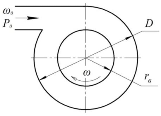
Figure 1.
Model of the translational−rotational movement of the liquid flow.
In the context of the steady translational−rotational movement of incompressible liquid along the tube axis of the vortex heat generator, the rotational velocity depends on the distance to the tube axis rв. In this case, the liquid is affected (conversely to the motion) by the viscosity force (i.e., friction) characterized by the resistance factor ξ:
Along the flow line, the liquid pressure decreases according to the following law:
The velocity moment M = ωφr varies due to the viscosity force action. To identify the velocity of the heat medium flow along the operating path of the vortex heat generator, determine a fluid momentum within a tube section with dx length. Assume the vortex radius as a drв variable in terms of viscous flow along the path. 2Πrвdrв is the gap crossing within which the liquid vortex is moving. The fluid momentum towards the fluid line per time unit varies by value. The change in the fluid momentum is equal to the impulse forces (i.e., forces of pressure and friction) acting over the same period within the selected section. Taking into consideration the equation of continuity and the constant velocity of movement along the tube axis in the cylindrical coordinates, the pressure force within dx is represented as follows:
Substituting dP from expression [18], the expression for pressure force is derived as follows:
In this context, ωφ is the rotational velocity of the liquid, determined using the following expression [21]:
The solution of the equation will be as follows:
where a and b are constants.
Expression (6) demonstrates that there are two rotational moments of the liquid. Moment one is described by means of the equation below:
The motion is characterized by a minimum change in velocity with rв radius, in analogy with the solid circulation. Moment two is described by means of the following equation:
being a potential rotation, i.e., rotω = 0. The potential rotation starts from some radius rв, i.e., if r ≥ rв. rв radius, being a vortex radius, is determined by means of the equality between the liquid pressure at the vortex surface and the external pressure P, i.e., r = rв, whereas the a and b constants are identified from the boundary conditions. Determine the friction force at motion as . Hence, in terms of the translational−rotational movement, the force balance is given by the following equation:
Transform expression (9) and reduce it to the following form:
As, , which follows from continuity conditions, then:
The application of expression (11) to the transformed equation of force balance (10) will result in the following:
The analysis of the generated equation explains that if the initial velocity is , then derivative has a positive sign and the liquid accelerates along the flow; conversely, the liquid decelerates. Hence, in order to increase the velocity up to the terminal one, it is required to develop adequate conditions for the liquid getting into the working space of the vortex heat generator. If:
then derivative turns to infinity, i.e., a crisis of flow takes place. In terms of the translational−rotational motion, the translation velocity of the liquid within a long tube cannot pass continuously through such a velocity value as . The last expression is the terminal or critical velocity of the liquid flow. While achieving its terminal velocity, the liquid changes from a steady-state flow into the pulsated one.
At the lateral vortex surface (i.e., at the surface of a cylinder with rв radius), elastic centrifugal waves arise resulting from the availability of the centrifugal forces. The velocity of the waves achieves the following sound velocity value [13]:
This is a value of the terminal (critical) value of the translation liquid flow involving Equation (9). Consequently, ωкp = s.
A continuous transition through the terminal velocity is possible in terms of the translational−rotational motion within a varying-section tube, as well as in terms of useful external operation (for instance, if the operation is connected with heat generation based on the cavitation effects). The abovementioned favors pressure decrease, cavitation effect intensification, and the improvement of the heat exchange process within the output unit of the vortex heat generator, indicating its energy efficiency. The high degree of the heat medium flow torsion at the expense of vortex flows, originated by the input and output specific devices, i.e., an input turbulizing nozzle and an internal vortex liquid flow accelerator, is a distinctive feature of the tube vortex heat generator.
3. Results and Discussion
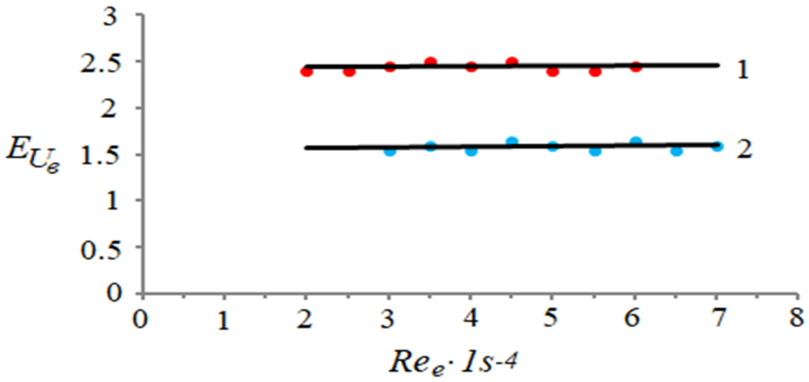
To evaluate the influence of the vortex device efficiency on the vortex heat generator operation, comparative experiments were carried out. The vortex heat generator performance was examined by means of introducing the tangential liquid with both the vortex accelerator of a liquid flow and without it. The experiment was to assess Euler’s number (as an index of velocity-pressure ratio) under various loads on the heat generator path. The loads are specified as numbers. Figure 2 compares the Euler’s numbers of the working path of the vortex heat generator with the installed vortex accelerator and without it. The dependences explain that in terms of similar hydrodynamic and thermal loads on the vortex heat generator path, on average, its efficiency is 35% higher if a vortex accelerator of the fluid flow is installed.
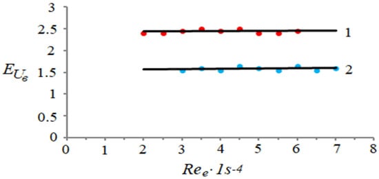
Figure 2.
Dependence of the Euler’s number of an operating path of the vortex heat generator on the path load: (1) heat generator with the installed vortex accelerator of the liquid flow and (2) heat generator without the vortex accelerator of liquid flow.
Structural Characteristics of the Experimental Vortex Heat Generator
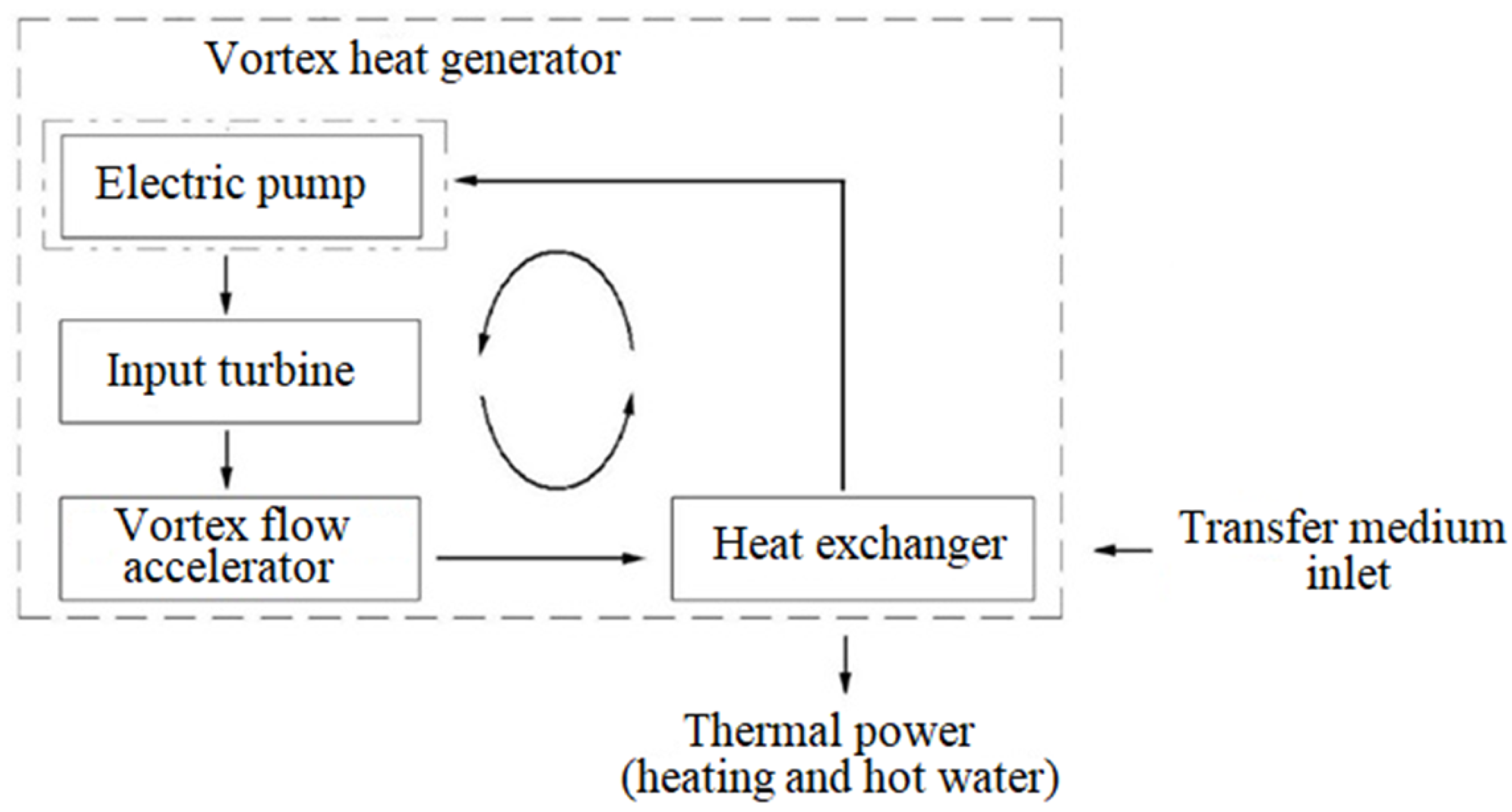
The motion of the “Newtonian” liquid medium involves a specific apparatus design of the hydrodynamic process of the translational−rotational motion. Within the research, a fundamentally new type of a vortex hydrodynamic facility for heat generation has been designed, manufactured, and analyzed. The facility is based on the translational−rotational motion of a medium favoring the generation of cavitation effects. As a result, the liquid is heated up to 70–80 °C. Figure 3 presents the basic configuration of the vortex heat generator.
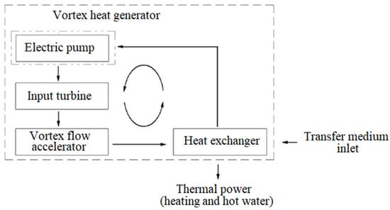
Figure 3.
Basic configuration of the vortex heat generator.
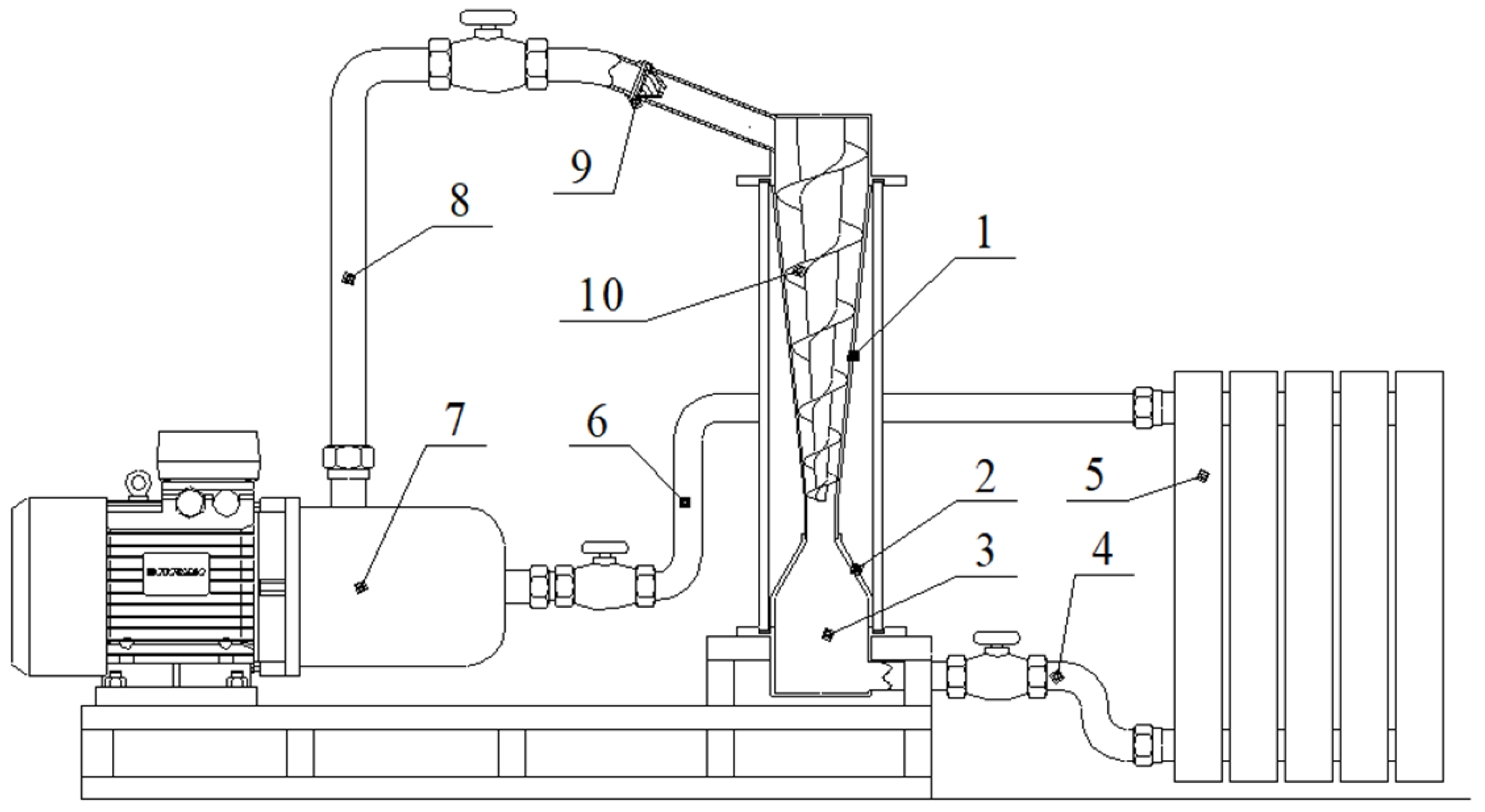
The basic configuration of the vortex heat generator was applied to develop a mathematical model of the influence of the facility structural parameters on its hydrodynamic characteristics. Figure 4 demonstrates the structural design of a vortex heat generator built in the experimental stand equipped with measuring instruments.
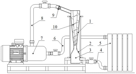
Figure 4.
Structural design of the vortex heat generator: (1) main body (confuser); (2) diffusor; (3) cushion chamber; (4) export pipeline; (5) heat exchanger; (6) return pipeline; (7) pump; (8) supply pipeline; (9) turbulizing nozzle; (10) vortex flow accelerator.
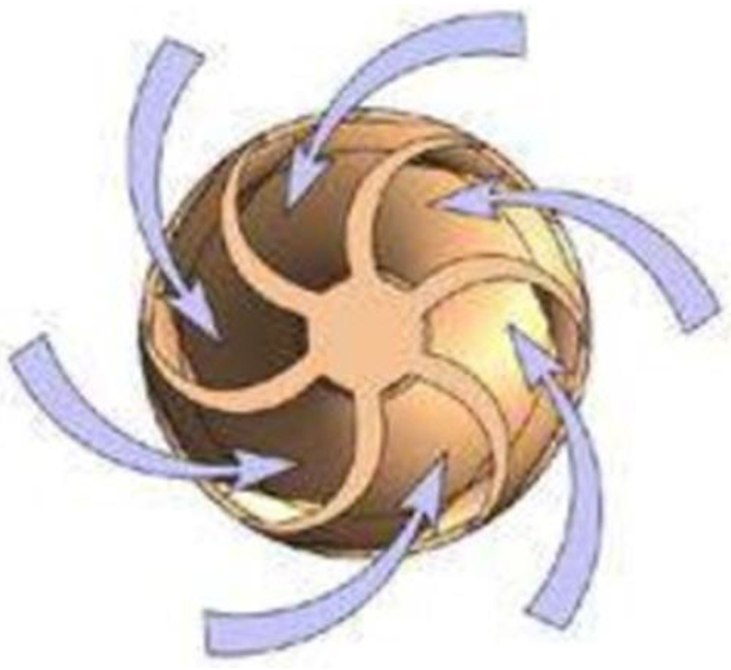
The distinctive feature of the designed vortex heat generator is that its body is made in the form of the Venturi pipe. A conical-shaped vortex flow accelerator with a decreasing pitch is in a confuser share. A vortex turbine in the form of a turbulizing nozzle is in the generator input (Figure 5).

Figure 5.
Basic configuration of the vortex turbine.
The designed and manufactured vortex heat generator was built in an experimental stand equipped with thermal monitoring tools to test its hydrodynamic indices. Figure 6 shows a general view of the experimental stand (a) and the movement of uncompressed gas (heat carrier) along the working space of the vortex generator, which precedes the cavitation mode (b). During the experiment, temperature and pressure were measured with a radial thermomanometer MT-80-TM (6 bar, 120 °C). For the measurements of the coolant temperature inside the device, a thermal imager brand Flir C2 was employed. Power and energy consumption were measured by meters brand NIK 2303L AR3 (T) 1000.MS.11, mounted in the panel KVPA.
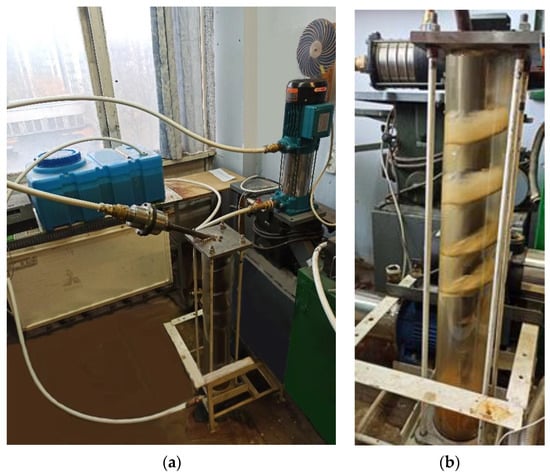
Figure 6.
The experimental stand: (a) overview of the installation; (b) during the experiment.
Optimum operation of the facility should involve a mathematical model, taking into consideration the effect of the actuating elements geometry on its hydrodynamic indices, depending on the medium characteristics. To perform calculations according to a mathematical model, a software block has been developed in the MathCad package. This block is based on the use of methods of computer modeling of continuums. In the case discussed in this paper the structure of a substance is of no interest or is negligible compared to its volume, so the substance was modeled as a continuous medium (the internal structure of the medium was not taken into account). For this purpose, CFD (computational fluid dynamics) software was employed in the modeling [22].
Using the CFD method, the elements presented in Figure 7 were applied in the formulation and solution of equations for the distribution of the velocities, pressure, density, and temperature of the medium.
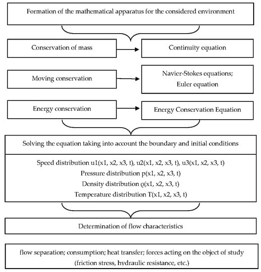
Figure 7.
Software block scheme of the computational fluid dynamics method.
The system of linear differential equations in the software block consists of: equations of motion (Navier−Stokes equations or Reynolds-averaged Navier−Stokes equations for cases describing turbulent flows), continuity equations, energy conservation equations, equations of state, and initial and boundary conditions. Figure 8 shows an analytical model for the mathematical modelling of the hydrodynamic motion inside the working space of the device [23].

Figure 8.
Analytical model to simulate the speed mode of the vortex cavitation facility.
In Figure 8, means the medium line. In this context, index 1 corresponds to the medium channel inlet and index 2 is its outlet. In this case, the motion will be performed towards the negative direction, as for the radial axis; hence, the velocity value should be negative as well. Considering the assumption that secondary flows are not available within the working gap, the axial velocity component and the angular one can be set to zero. If only the radial velocity component is taken into consideration, then:
where the coordinate is perpendicular to the scheme shown in Figure 8.
Within the context of a steady-state process, the motion equations, after having taken into consideration the assumptions and disregarding the changes in physical values along the axial coordinate, are as follows:
Furthermore, the continuity equation is as follows:
Generally, the radial velocity component is a function of two variables, i.e., the radial coordinate and the angular coordinate. While applying continuity Equation (15), introduce the following alternation:
where is a function depending only on the coordinate.
For the considered scheme, the components of the tensor of deformation velocity, differing from zero, will be as follows: , , . To proceed from stress tensors within motion Equations (17) and (18) to the velocity characteristics, apply a rheological equation of state for Newtonian liquid in the form of:
where is viscosity, and are indices corresponding presently with coordinate axes . After corresponding substitutions in Equations (17) and (18), we obtain the following:
To avoid the use of pressure ingredients in Equations (21) and (22), differentiate Equation (21) on coordinate . Equation (22) is differentiated on coordinate . After substitution and transformation, we get the following:
The solution of Equation (23) is as follows:
To identify the radial velocity component, use substitution (21) and obtain:
Equation (25) involves three constant integrations. Derive two integration constants using the following boundary conditions:
Determine one more integration constant with the help of the continuity equation in the integral form:
where is a channel width and constitutes the performance of the device supplying service fluid (for instance, a pump). While substituting and transforming adequately, obtain expressions for the integration constants:
The operation of the vortex heat generator was analyzed using a mathematical modelling method on the developed mathematical model. The following initial parameters of the initial data for the calculations were specified as follows: m3/s; ; mm; mm; and mm. For these values, the inlet and outlet channel widths are = 0.207 m and = 0.018 m, respectively. The surface of the radial component values (11) has been derived for variability ranges such as and . Figure 9 shows the results of the calculations.
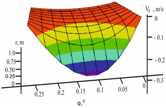
Figure 9.
3D graph of Vr velocity changes for the selected parameters.
As Figure 9 demonstrates, for the selected parameters, the speed rate of the transfer medium along the vortex cavitation device cannot approach critical sound velocity, favoring the initiation of the active cavitation process. Figure 10 presents the variability dependencies of both the geometric and the head characteristics of the device in accordance with the developed mathematical modification. The change in the speed rate has been demonstrated in regard to different performance values (i.e., if Q1 = 1∙10−3 m3/s; if Q2 = 3∙10−3 m3/s, and if Q3 = 10∙10−3 m3/s), as well as invariant parameters, assumed while plotting the dependences shown in Figure 3. It is understood from Figure 10a that certain ratio parameters initiate entire areas of intensive medium motion (space between curves) where terminal velocities, preceding the cavitation occur. Figure 10b shows changes in the speed rate depending on different inclinations ( if γ = 25°; if γ = 11° and if γ = 5°) and performance levels such as Q2 = 3∙10−3 m/s. An analysis of the dependencies supports the idea that the inclination influences heavily influences the speed rate within the working space of the heat generator.
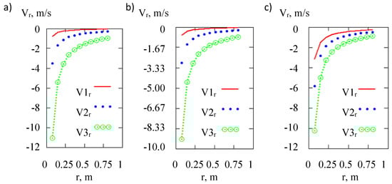
Figure 10.
Changes of velocity: (a) in terms of different values of pipe performance, (b) in terms of different inclination values , and (c) in terms of different values of channel width .
Figure 10c shows the results of the channel width effect ( if = 130 mm; if = 70 mm; and if = 40 mm) on the speed rate . For this purpose, the following parameters have been assumed:, m3/s. The values of the other parameters correspond to those presented in Figure 10b. Velocity increases along with the increase in V-distance depending on the increase in the friction force. It should be noted that the graphs in Figure 10 correspond to the central share of the channel, i.e., they were obtained under .
On the basis of the experimental and analytical studies also using the physical and mathematical model of the vortex effect, the most adequate criterion base for assessing the operation of a vortex heat generator has been developed, which includes the following elements:
Geometric: , which is the dependence of the flow area of the braking device to the area of the vortex chamber, characterizing the degree of flow compression, and , which is the dependence of the length of the vortex chamber to its diameter, which characterizes the size of the zone of a stable vortex before the flow is straightened and decelerated.
Kinematic: , which is the dependence of the radial component of the velocity to the average flow velocity in the inlet section of the confuser; where Q1 is the coolant flow, 0.26 l/s, and is the radial velocity component, 0.27 m/s.
Thermodynamic:
is the Prandtl number, and is the Froude number;
is the Euler’s number, and is the Strouhal number.
Having expressed the thermal efficiency of the heat generator through the above-mentioned base of parameters, it is possible to constructively design a vortex heat generator of a given thermal productivity:
The analysis of the empirical and analytical dependencies during the testing of a vortex heat generator makes it possible to determine the concept of mathematical modeling of the vortex flow of an incompressible gas in a vortex heat generator. In addition, it is possible to determine the initial and boundary conditions of the process in order to verify and derive the empirical coefficients.
4. Conclusions
1. Analytical and experimental studies of the hydrodynamics of the translational−rotational motion of incompressible gas flow within a vortex heat generator have been carried out.
2. Critical (terminal) velocity of the translational−rotational motion of incompressible gas has been identified analytically. It has been defined that it is set to sound velocity, i.e., ωкp = s.
3. It has been determined that in order to improve the energy efficiency (i.e., thermal generation) of the heat generator, its body should have the form of a varying-section tube.
4. It has been proven that in the process of introducing the tangential liquid into the working space of the vortex heat generator, the availability of a vortex flow accelerator improves its energy efficiency by 35%.
5. A mathematical model and a simplified analytical one have been developed to simulate the medium motion inside the vortex channel with stationary components. In addition, a software block has been developed in the MathCad package. The obtained models have been applied to demonstrate terminal areas with the intensive cavitation mode. The mathematical model has been applied to determine the effect of the basic geometric and hydrodynamic parameters of the facility on its energy efficiency indices. Critical areas, with the most intensive potential of cavitation zones, have been demonstrated by means of the models. The findings are as follows:
- −
- in proportion to the vortex formation, static temperature aligns to the vortex radius;
- −
- radial temperature gradient increases along with the vortex approaching the confuser outlet; and
- −
- the motion of the free vortex of incompressible gas results in the intensive turbulent heat exchange characterized by the availability of high-gradient static pressure being normal towards the averaged motion velocity. In this context, the incompressible gas temperature varies.
6. An innovative type of a vortex heat generator with variable geometry of the working space has been designed, manufactured, and tested. The facility is in the form of the Venturi tube with a vortex flow accelerator inside.
7. Further studies are intended to be focused on the synergistic effect between the hardware design of the heat generator and the energy efficiency. As part of this research, the design of equipment will be improved. Studies will be carried out on the wobbling of the angle of attack of the vortex device in order to increase the low-frequency oscillations generated in the process of the vortex motion along the vortex device. In addition, the design of the vortex nozzle at the system inlet will be worked out, the task of which is to generate high-frequency oscillations. The superposition of low-frequency oscillations on high-frequency oscillations leads to devices with a maximum energy efficiency. Such works are very relevant for reducing energy consumption from non-renewable energy sources, which is an important issue in present-day thermal power engineering.
Author Contributions
Conceptualization, V.N., R.D., E.C.C., N.H., B.J., K.W. and A.S.; methodology, V.N., R.D., E.C.C., N.H., B.J., K.W. and A.S.; software, V.N.; validation, V.N., R.D., K.W. and E.C.C.; formal analysis, V.N., R.D., E.C.C., N.H., B.J., K.W. and A.S.; investigation: V.N. and R.D.; writing—original draft preparation, V.N. and R.D.; writing—review and editing, V.N. and R.D.; visualization, V.N.; supervision, A.S. All authors have read and agreed to the published version of the manuscript.
Funding
This research received no external funding.
Institutional Review Board Statement
Not applicable.
Informed Consent Statement
Not applicable.
Conflicts of Interest
The authors declare no conflict of interest.
References
- Kolb, A.; Pazynich, Y.; Mirek, A.; Petinova, O. Influence of voltage reserve on the parameters of parallel power active compensators in mining. In E3S Web of Conferences; EDP Sciences: Les Ulis, France, 2020; Volume 201, p. 01024. [Google Scholar] [CrossRef]
- Nikolsky, V.; Kuzyayev, I.; Alieksandrov, O.; Ved, V.; Pugach, A.; Yaris, V.; Lopatin, V. Analytical and experimental studies into the processes of hydrodynamics and heat exchange in the channels of disk pulse devices. East.-Eur. J. Enterp. Technol. 2019, 4, 15–23. [Google Scholar] [CrossRef]
- Nikolsky, V.; Kuzyayev, I.; Dychkovskyi, R.; Alieksandrov, O.; Yaris, V.; Ptitsyn, S.; Tikhaya, L.; Howaniec, N.; Bak, A.; Siudyga, T.; et al. A Study of Heat Exchange Processes within the Channels of Disk Pulse Devices. Energies 2020, 13, 3492. [Google Scholar] [CrossRef]
- Nikolsky, V.; Oliynyk, O.; Ved, V.; Svietkina, O.; Pugach, A.; Shvachka, A. Design and study of the energy efficient unified apparatuses for energy technological manufacturing. East.-Eur. J. Enterp. Technol. 2018, 3, 59–65. [Google Scholar] [CrossRef] [Green Version]
- Girin, O.; Kuzyayev, I.; Nikolsky, V.; Yaris, V. Discovering and Modelling the Wave-Like Shapes on the Surface of Metal Deposits, being Electrodeposited under the Force Impact. Key Eng. Mater. 2020, 844, 135–145. [Google Scholar] [CrossRef]
- Promtov, M.A.; Akulin, V.V. Mechanisms for generating heat in a rotary-impulse apparatus. Vestn. TGTU 2015, 11, 103–106. (In Russian) [Google Scholar]
- Hirschi, R. Prediction par Modelisation Numerique Tridimensionnelle des Effets de la Cavitation a Poche dans les Turbomachines Hydrauliques. Ph.D. Thesis, Ecole Polytechnique Federale de Lausanne, Lausanne, Switzerland, 1998. [Google Scholar]
- Ja, V.; Hosangadi, A.; Arunajatesan, S. Simulations of Cavitating Flows Using Hybrid Unstructured Meshes. J. Fluids Eng. 2001, 123, 331–340. [Google Scholar]
- Hirschi, R.; Dupont, P.; Avellan, F. Centrifugal pump performance drop due to leading edge cavitation: Numerical predictions compared with model tests. J. Fluids Eng. 1997, 120, 705–711. [Google Scholar] [CrossRef]
- Singhal, N.H.; Athavale, A.K.; Li, M.; Jiang, Y. Mathematical basis and validation of the full cavitation model//Tr. ASME. J. Fluids Eng. 2002, 124, 17–624. [Google Scholar] [CrossRef]
- Senocak, I.; Shyy, W. Evaluation of cavitation models for Navier-Stokes computations. In Proceedings of the 2002 ASME Fluids Engineering Division Summer Meeting, Montreal, QC, Canada, 14–18 July 2002. [Google Scholar]
- Krzemień, A.; Więckol-Ryk, A.; Smoliński, A.; Koteras, A.; Więcław-Solny, L. Assessing the risk of corrosion in amine-based CO2 Capture Process. J. Loss Prev. Process Ind. 2016, 43, 189–197. [Google Scholar]
- Wojtacha-Rychter, K.; Smoliński, A. Multi-component gas mixture transport through porous structure of coal. Fuel 2018, 233, 37–44. [Google Scholar] [CrossRef]
- Smoliński, A.; Howaniec, N.; Gasior, R.; Polański, J.; Magdziarczyk, M. Thermal conversion of low rank coal, flotation concentrate and refuse derived fuel in the process of steam co-gasification to hydrogen-rich gas. Energy 2021, 235, 121348. [Google Scholar] [CrossRef]
- Nikolsky, V. Development and study of contactmodular heating system using immersion combustion units. East.-Eur. J. Enterp. Technol. 2015, 4, 31–35. [Google Scholar]
- Nalavade, S. Pioneering highly insulating materials for the heat transfer enhancement using the flow divider type inserts. Mater. Today Proc. 2021, 46, 2647–2652. [Google Scholar] [CrossRef]
- Goh, L.H.K.; Hung, Y.M.; Chen, G.M.; Tso, C.P. Entropy generation analysis of turbulent convection in a heat exchanger with self-rotating turbulator inserts. Int. J. Therm. Sci. 2021, 160, 106652. [Google Scholar] [CrossRef]
- Ved, V.; Nikolsky, V.; Oliynyk, O.; Lipeev, A. Examining a cavitation heat generator and the control method over the efficiency of its operation. East.-Eur. J. Enterp. Technol. 2017, 4, 22–28. [Google Scholar] [CrossRef]
- Dychkovskyi, R.O. Forming the bilayer artificially created shell of georeactor in underground coal well gasification. Nauk. Visnyk Natsionalnoho Hirnychoho Univ. 2015, 5, 37–42. [Google Scholar]
- Promvonge, P.; Promthaisong, P.; Skullong, S. Experimental and numerical heat transfer study of turbulent tube flow through discrete V-winglets. Int. J. Heat Mass Tran. 2020, 151, 119351. [Google Scholar] [CrossRef]
- Biriuk, V.V.; Serebriakov, R.A. Vortex hydraulic heat generator//Scientific Messenger of National University of Life and Environmental Sciences of Ukraine. Ser. Equip. Energetics AIC 2015, 209, 157–160. [Google Scholar]
- Uhl, B.; Brotz, F.; Fauser, J.; Krüger, U. Development of Engine Cooling Systems by Coupling CFD Simulation and Heat Exchanger Analysis Programs. SAE Tech. Pap. Ser. 2001, 111, 13–22. [Google Scholar] [CrossRef]
- Kyzyayev, I.M.; Svidersky, V.A.; Petukhov, A.D. Simulation of extrusion and extrudes in the process of polymer processing: Monograph, in two parts, Part 2—Kyiv: NTUU ‘KPI’ Publishing House. Politekhnika 2016, 217, 141–145. [Google Scholar]


Publisher’s Note: MDPI stays neutral with regard to jurisdictional claims in published maps and institutional affiliations. |
© 2022 by the authors. Licensee MDPI, Basel, Switzerland. This article is an open access article distributed under the terms and conditions of the Creative Commons Attribution (CC BY) license (https://creativecommons.org/licenses/by/4.0/).