Article

Optimal Design of Automatic Generation Control Based on Simulated Annealing in Interconnected Two-Area Power System Using Hybrid PID—Fuzzy Control

by
Muntasir A. Magzoub
* and
Thamer Alquthami
Department of Electrical and Computer Engineering, King Abdulaziz University, Jeddah 21589, Saudi Arabia
*
Author to whom correspondence should be addressed.
Energies 2022, 15(4), 1540; https://doi.org/10.3390/en15041540
Submission received: 21 December 2021 / Revised: 12 February 2022 / Accepted: 14 February 2022 / Published: 19 February 2022
(This article belongs to the Topic Power System Modeling and Control)

Abstract

:
Electricity demand continues to rise on a daily basis. The most difficult task is ensuring that customers have access to reliable, high-quality electricity regardless of the weather. Automatic generation control (AGC) accomplishes this by keeping the target output power and frequency constant despite load fluctuations. This paper presents a hybrid PID-fuzzy controller for optimal automatic generation control in a two-area interconnected power system. A comparative analysis of the proposed controller was performed with the PID controller. The parameters of the both controllers were developed by simulated annealing (SA) techniques in order to obtain the best dynamic performance. MATLAB Simulink software was used to simulate the models. The results of the simulation for the two-area power system based on simulated annealing using the hybrid PID–fuzzy controller showed superior performance in comparison to a conventional PID controller.

1. Introduction

In recent years, the rapidly increasing load demand in power systems has resulted in substantial and random variation in load. As load increases, the frequency of the system decreases, leading to under-frequency conditions; therefore, the speed of the generator reduces as well. Similarly, with sudden load loss, the frequency increases, resulting over-frequency conditions [1,2]. This variation causes power system disturbances to occur. Hence, to eliminate this variation and improve the system’s performance, automatic generation control (AGC) must be designed for power systems to reduce the losses and balance the total generating power with the total load demand [3,4]. An interconnected power system consists of two or more areas connected through a tie-line, with each area having an equivalent generator, turbine, and governor system [5]. To the frequency remains at a constant value, a controller must be used. One controller type is the proportional Integral derivative (PID) controller, which is one of the most commonly used. The gain of the controller provides high stability, but for the case of complex characteristics and slow response, a PID integrated with a fuzzy logic controller was constructed [6]. Recently, various optimization techniques have been proposed including: (i) particle swarm optimization (PSO), (ii) bacteria foraging optimization (BFO), (iii) genetic algorithm (GA), (iv) simulated annealing (SE), (v) differential evolution (DE), (vi) butterfly optimization (BO), (vii) ant colony optimization (ACO), and (viii) pattern search (PS) [7,8,9]. Electric vehicles and grids with a high pentration of renewable energy sources (EVs) such as wind and solar can significantly improve the time response of the system as well as lower the cost of unexpected power imbalances between output and demand, Imitate learning like transfer learning aims to increase the learning efficiency of agents [10]. The automatic generation control (AGC) based on the frequency regulation market and generation tribe (VGT) is implemented using two algorithms: a new real-time optimal mileage based dispatch (OMD) and a consensus transfer Q-learning (CTQ). Both algorithms can be accelerated, and the AGC period requirement is met. Furthermore, CTQ employs a behavior transfer to use existing knowledge of source tasks to generate a new optimization job based on their similarities [11,12]. A unique adaptive distributed auction-based algorithm (ADAA) is utilized to swiftly identify a high-quality dispatch scheme in a distributed way and minimize the power deviation between the dispatch command and the real power regulation output due to its fast convergence speed and model-free feature. ADAA can converge faster and reduce communication traffic since it simply uses an adaptive swap size depending on the instant optimization findings [13]. Several researchers have studied various control techniques for the automatic control generation (AGC) of innumerable connected power systems. The main objective of these studies was to use a control algorithm in AGC to improve system performance through damping the variation in frequency and stabilizing the fluctuation in the tie-line power flow. Despite the fact that most control schemes improved the LFC system’s performance, the controller must be readjusted whenever the disturbance changes, according to the majority of the literature. Moreover, Due to the complexity of interconnected power systems with a large number of nonlinear properties, Mamdani implemented the first fuzzy logic control algorithm on a steam engine after Zadeh introduced fuzzy set theory. Fuzzy logic controllers are some of the controllers better suited to these systems; they have several advantages: (i) providing a featured of copy data quickly and efficiently, (ii) having fast interaction during the process, and (iii) providing rules extracted from human brain and experts [14,15]. The authors of [16] compared different controllers in a deregulated power system for diverse multiple-area sources using differential evolution (DE) and genetic algorithm (GA). The results show that the PID controller with DE performed better. Other authors of [17] improved the structure of the multisource interconnected power system (IPS) where AGC is achieved using an integral proportional derivative (IPD) controller. The results demonstrated the superiority of the performance of the system with regard to system frequency overshoot (Osh), undershoot (Ush), and settling time (Ts). The authors of [18] employed a differential evolution approach to improve AGC while taking nonlinearity into account as a governor deadband. In order to improve the performance of a single-area AGC in [19] uses a more appropriate technique based on increasing the controller’s transfer function using Laurent series to boost the controller performance of two-area AGC systems, the Firefly Algorithm outperformed various optimization strategies [20]. The gravity search technique was designed in [21,22] to increase the reaction to a deviation in frequency between multi-area power systems. This algorithm is based on certain advanced controllers such as ISE and PI.The authors of [23,24] compared the implementation of a PI controller with a fuzzy logic controller in two and three areas with diverse sources for each area. The results showed that fuzzy logic controller performed better than the PI controller, considering overshoot and settling. Others [25] proposed a new method of tuning the fuzzy logic that is quick when setting deregulated multi-area power systems (thermal, gas, and photovoltaic). The findings demonstrated that this method of tuning the logic helps to quickly reduce external error. The authors of [26,27] proposed a load frequency controller for multi-area single power systems. A parallel connection of a fuzzy logic controller with a PID controller for three-area automatic generation control was tested for dynamic improvement when load disturbance occurred in one area. The results showed that the fuzzy controller performed better. Various scenarios of renewable energy penetration in a two-area power system presented in [28] with different step load demand disturbances based on the ant colony algorithm. The results demonstrated that their method supported the frequency stability of the system [29]. Automatic generation control is considered an interaction between load frequency control (LFC) and an automatic voltage regulator (AVR), as shown in Figure 1. This interaction is simply a combination of frequency control to include an excitation system, which is part of LFC and voltage control through the governor control using AVR [30]. The ideal parameters for the FOPID controller are determined using the teacher-learning-based optimization (TLBO) technique, with the objective function being the integral time-multiplied absolute error (ITAE). By comparing the suggested controller to a PID controller, the superiority of the proposed controller was demonstrated [31]. Researchers [32] reported three different types of levitation control algorithm. The control performance of these algorithms was tested for the optimization of magnet current. PID + fuzzy control effectively lowered magnet current fluctuation and reduces the RMS value of magnet current; PI+P hybrid control effectively reduced the impact of mutation interference on the current and reduced the current fluctuation range.
Based on the literature review mentioned above, we found that most studies concentrated on generation control in power systems such as thermal, hydro, and gas according to the number of areas connected in the system, which comprised large power plants. Therefore, each area consisted of many parameters that affect the power flow and frequency of the tie. In this study, for two interconnected areas with unequal power systems, we optimally designed an intelligent controller based on the simulated annealing technique to enhance the frequency stability. We developed the objective function using the optimization technique to coordinate the PID controller and to obtain the upper and lower boundaries of the fuzzy logic controller membership function. The contribution of this paper is briefly summarized as the description of the behavior of the frequency and tie-line power flow fluctuations in the presence of step load demand perturbation, and we performed a comparative study of two controllers with two cases of disturbances in term of settling time, peak amplitude, and peak time.

2. Power System Mathematical Model

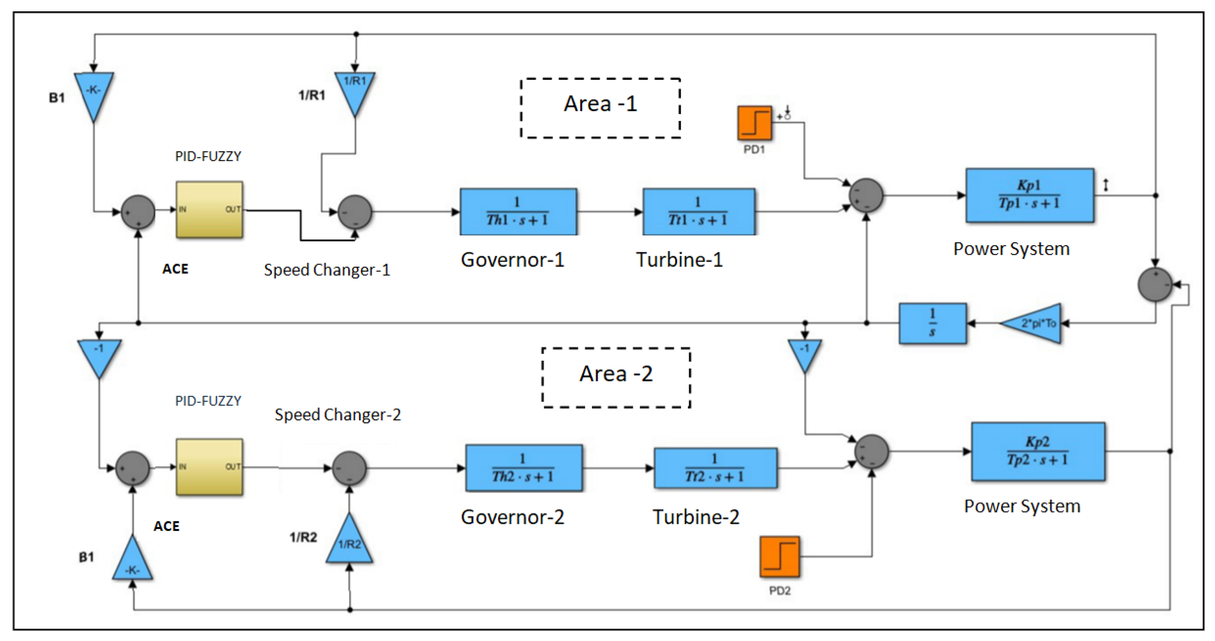
The ALFC loop needs to adapt the output power of the generator to the load demand by manipulating the mechanical turbine output. Two loops are used for this, primary and secondary. The response time of the primary loop is fast. The second-order loop, conversely, operates slowly, eliminating small frequency fluctuations [8]. The primary loop’s time response is constrained by the turbine’s response time, whereas the secondary loop’s response can be modified by properly tuning its integral gain. The ALFC components are shown in Figure 2 and their mathematical models are described below [30,31,32,33,34] in Figure 3 and Figure 4.

2.1. Speed Governor Representation

The speed governor responds to changes in frequency ( Δ f) by adjusting the output power command ( Δ P g ) to the hydraulic amplifier. The relationship that governs the speed governor operation is:
Δ P g ( s ) = Δ P r e f ( s ) 1 R Δ f ( s )
where Δ P r e f is the power setting used as a reference, and and R (Hz/pu Mw) is the generator’s control parameter or droop feature.

2.2. Hydraulic Amplifier Representation

The hydraulic amplifier responds to the command to switch ( Δ P g ) the speed governor’s power by adjusting the position of the steam control valve, which causes changes in the power transferred to the turbine ( Δ P v ). The input–output relationship of a hydraulic amplifier is [31]:
Δ P v ( s ) = 1 1 + s T h Δ P g ( s )
where T h is the time constant of the hydraulic amplifier.

2.3. Turbine Representation

In the steady state, the turbine output is in equilibrium with the electromechanical air gap output, so no acceleration occurs and the velocity (frequency) remains constant. The fluctuations in turbine output in transient conditions are determined by the fluctuations in load demand. We used a turbine model without reheating, which is represented by the following linear transfer function [35]:
Δ P T ( s ) = 1 1 + s T τ Δ P v ( s )
where Δ P T is the change in turbine power, Δ P v is the change in valve power, and T τ is the turbine time constant.

2.4. Tie-Line Power Representation

If the load requirement of an area increases, the turbine regulator increases the output of the area by Δ P G i . The system absorbs the difference in power between the increased power generation and the increased load demand in one of the following ways: first, by reducing the kinetic energy of area W k i n , i ; second, increasing load consumption; third, increasing power exchange over the connection line Δ P t i e , i [9]. This can be mathematically represented as [35]:
Δ P G i Δ P D i = W k i n , i t + Δ D i Δ f i + Δ p t i e , i
where Δ P D i is the change in area load requirements i, and D i is the frequency dependency of the load. Then, use the following relationships [35]:
W k i n = W k i n , i 0 ( f i f 0 ) 2 = W k i n , i 0 ( f 0 + Δ f i f 0 ) 2 W k i n , i 0 ( 1 + 2 Δ f i f 0 )
H i W k i n , i 0 p r i
where the steady-state kinetic energy is W k i n , i 0 , the steady-state frequency is f0, the inertia constant is H i , and the base rated power is P r i . Equation (4) becomes (in per unit) [32]:
Δ P G i Δ P D i = 2 H i f 0 + Δ D i Δ f i + Δ P t i e , i
The increase in tie-line power in a two-area power system can be stated as:
Δ P t i e , 12 = T 0 ( Δ δ 1 Δ δ 2 )
T 0 = p m a x , 12 cos ( Δ δ 1 Δ δ 2 )
where the synchronization coefficient is T 0 , the static tie-line transmission capacity is P m a x , 12 , and the incremental variations in the phase voltage in both tie-line ends are Δ 1 and Δ 2 . Using the relationship [33]:
Δ f 1 = 1 2 π d d t Δ δ i
Equation (8) becomes:
Δ P t i e , 12 ( s ) = 2 π s T 0 [ Δ f 1 d t Δ f 2 d t ]
Taking the Laplace transform for Equations (7) and (11), we obtain:
Δ p t i e , 12 ( s ) = 2 π s T 0 [ Δ f 1 ( s ) Δ f 2 ( s ) ]
[ Δ p G i ( s ) Δ p D i ( s ) Δ p t i e , 12 ( s ) ] G p ( s ) = Δ f i ( s )
where
G p ( s ) = K p 1 + s T p
K p = 1 D i , T p = 2 H i f 0 D i

3. Proposed Work

3.1. Tie-Line Bias Control

We introduce area control error to eliminate both frequency and tie-line variations as follows:
A C E 1 = Δ P t i e , 12 + Δ f 1
A C E 2 = Δ P t i e , 21 + Δ f 2

3.2. Optimum Parameters

To measure the dynamic performance of the automatic load frequency loop, we chose the integral square error (ISE). The ISE is calculated as:
I S E = ( Δ f 1 2 + Δ f 2 2 + Δ p 12 2 ) d t
We use an optimization technique to minimize the ISE of the system to achieve the optimal parameter of PID gains and frequency bias. The following are the variables that define the optimization variables:
x = [ P 1 I 1 D 1 P 2 I 2 D 2 B 1 B 2 ]
Optimization is limited by the range of decision variables as follows:
0 < P 1 < P 1 m a x 0 < I 1 < I 1 m a x 0 < D 1 < D 1 m a x 0 < P 2 < P 2 m a x 0 < I 2 < I 2 m a x 0 < D 2 < D 2 m a x 0 < B 1 < B 1 m a x 0 < B 2 < B 2 m a x
where P 1 m a x , I 1 m a x , D 1 m a x , P 2 m a x , I 2 m a x , and D 1 m a x are the maximum values of the proportional integral derivative gain for areas 1 and 2, respectively, and B 1 m a x and B 2 m a x are the maximum values of the frequency bias for area 1 and 2, respectively. The optimization method we used in this research is described next.

3.3. Optimization Algorithm

Simulated annealing is a simple but effective approach to solving optimization problems. Simulated annealing was performed in 1983 by Kirkpatrick et al., independent of Cerny in 1985 [35]. Simulated annealing is used to simulate the physical process that occurs when the minimum energy is generated, slowly cooling the solid until the structure finally freezes. The process starts with a state of s0 and ends after taking a maximum of kmax steps as clearly in Figure 3. The call neighbor (s) must then produce a randomly picked neighbor for a given state, and this randomly selected random neighbor (0, 1) must pick and return a value in the range [0, 1] that is uniform in unpredictability. As shown in Table 1, the annealing schedule is determined by the call temperature (r), which must create the using temperature while considering the proportion (r) of the time budget that has been increased [36].

3.4. Control Techniques

3.4.1. Conventional PID Controller

In industrial applications, PID controllers are used. These controllers are popular because of their simplicity, ease of design, low cost, and efficacy. They feature a simplified structural design and perform effectively in a range of situations. Proportional (P), integral (I), and derivative (D) are the three major parameters of the PID controller. By managing the three parameters in the PID controller’s algorithm, the controller provides control adapted to unique process requirements. However, the PID controller is inefficient due to non-linearity in this technique; nonetheless, the controller can provide control adapted to the needs of a certain process. The proportional, integral, and derivative terms are added to calculate the output of a PID controller. The final output is indicated by u ( t ) .
u ( t ) = K p e ( t ) + K d d e ( t ) d t + K i 0 t e ( x ) d ( x )

3.4.2. Fuzzy Logic Controllers

Power systems and tuning converters are the most common applications of fuzzy logic controllers. The system model must be built with traditional controller design, and control rules must be generated from model analysis. Due to nonlinearity, linearization of the system model is usually required and a linear controller is used to control the nonlinear system. A fuzzy logic controller (FLC) is a device that fuzzies controller inputs and derives correct fuzzy controls based on defined rules. The FLC output is then generated by defuzzying the derived fuzzy control decisions [6]. As a result, the main components of the FLC process are the inference engine, fuzzy defuzzying, and defined rules.

3.4.3. Proposed Hybrid PID–Fuzzy Controller

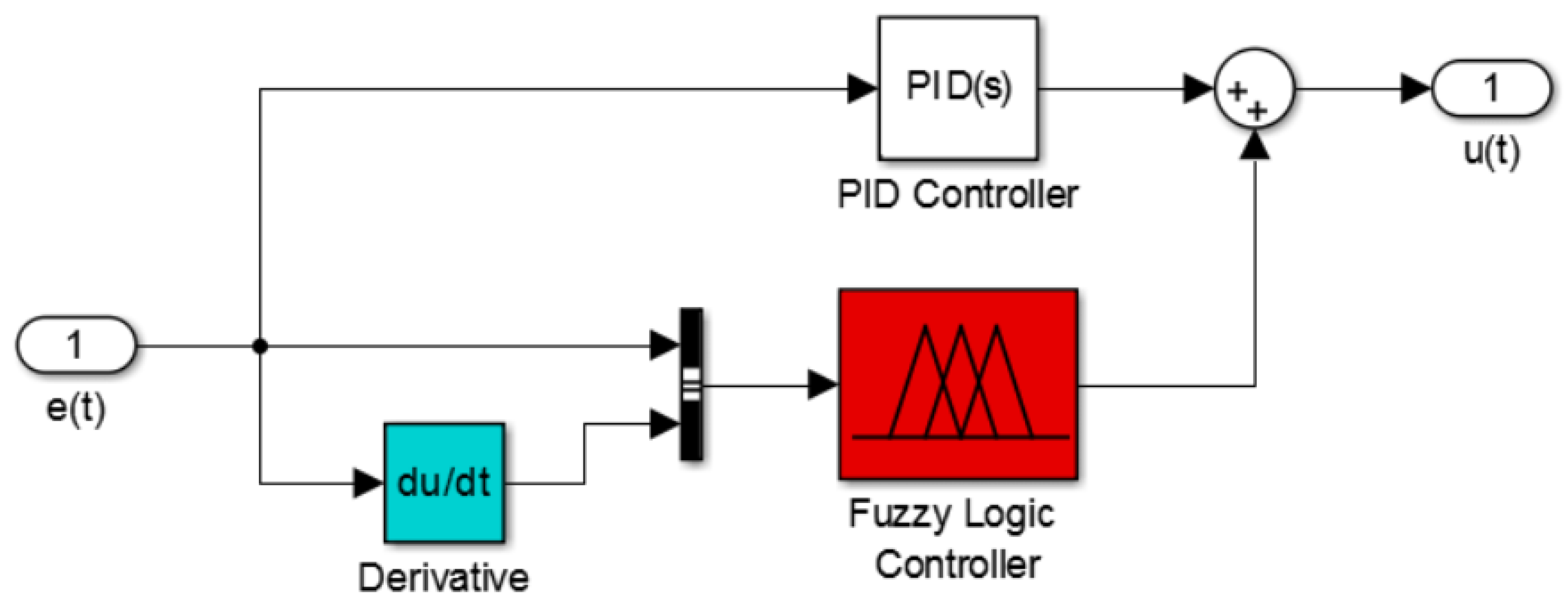
The proposed hybrid PID–fuzzy controller combines and tunes the classical PID and fuzzy PID controllers [36]. Figure 5 shows the MATLAB Simulink model of the proposed hybrid fuzzy–PID (PID–fuzzy) controller.

3.4.4. Rule Base for Fuzzy Logic System

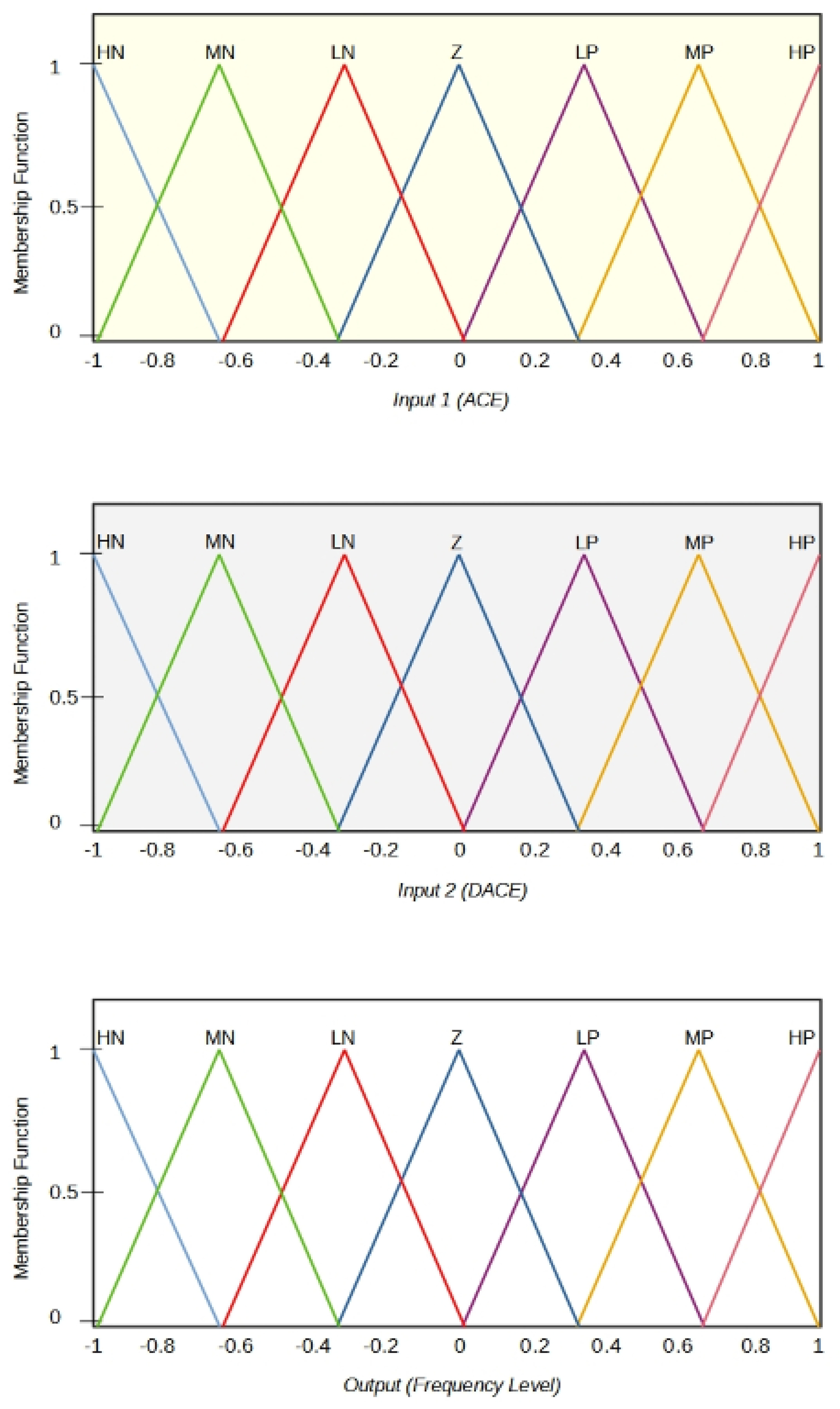
The behavior of fuzzy logic controllers is regulated by 49 rules using an if-and-then structures to design and control model for FLC Membership Functions (MFs) as shown in Figure 6. The rules based can be recorded in Table 2.

4. Results and Discussion

We built a Simulink model and scripting code in MATLAB using the MATLAB optimization toolkit for the two-area power system shown in Figure 2. The system parameters are shown in Table 3 [37].

4.1. Optimum Parameters Tuned

Table 4 shows the variables that were fine-tuned by the system. To determine the range of the optimization variables in [22], the effect of changing the integral gain and frequency bias on the integral square error was investigated separately for each area. Frequency bias is expressed as a percentage of the area frequency response characteristics ( b e t a ) with fixed frequency bias ( B 2 ) and gain ( P 1 , I 1 , and D 1 ) for area 1 and gain ( P 2 , I 2 , and D 2 ) for area 2.

4.2. Case Studies: Frequency and Tie-Line Power Response

Based on the obtained results for the two cases, we found that both of controllers can work independently in the presence of huge load fluctuations. However, in terms of robustness and stability, the PID–fuzzy controller is more robust and stable, due to preventing overshooting.
Basically, the two area power system parameters P1, I1, D1, P2, I2, D2, B1, and B2 were obtained to measure the integral squared error (ISE) using the SA technique. The input disturbance r change in load power was investigated in two scenarios.:
  • Case 1: the input disturbance is taken as d1 = 0.2 pu and d21 = 0.0;
  • Case 2: the input disturbance is taken as d1 = 0.0 pu and d21 = 0.2 pu.
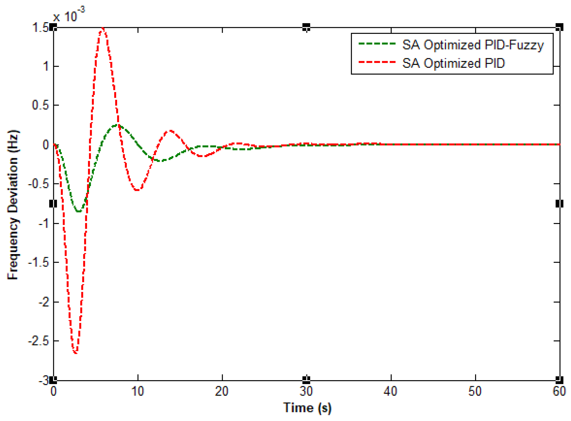
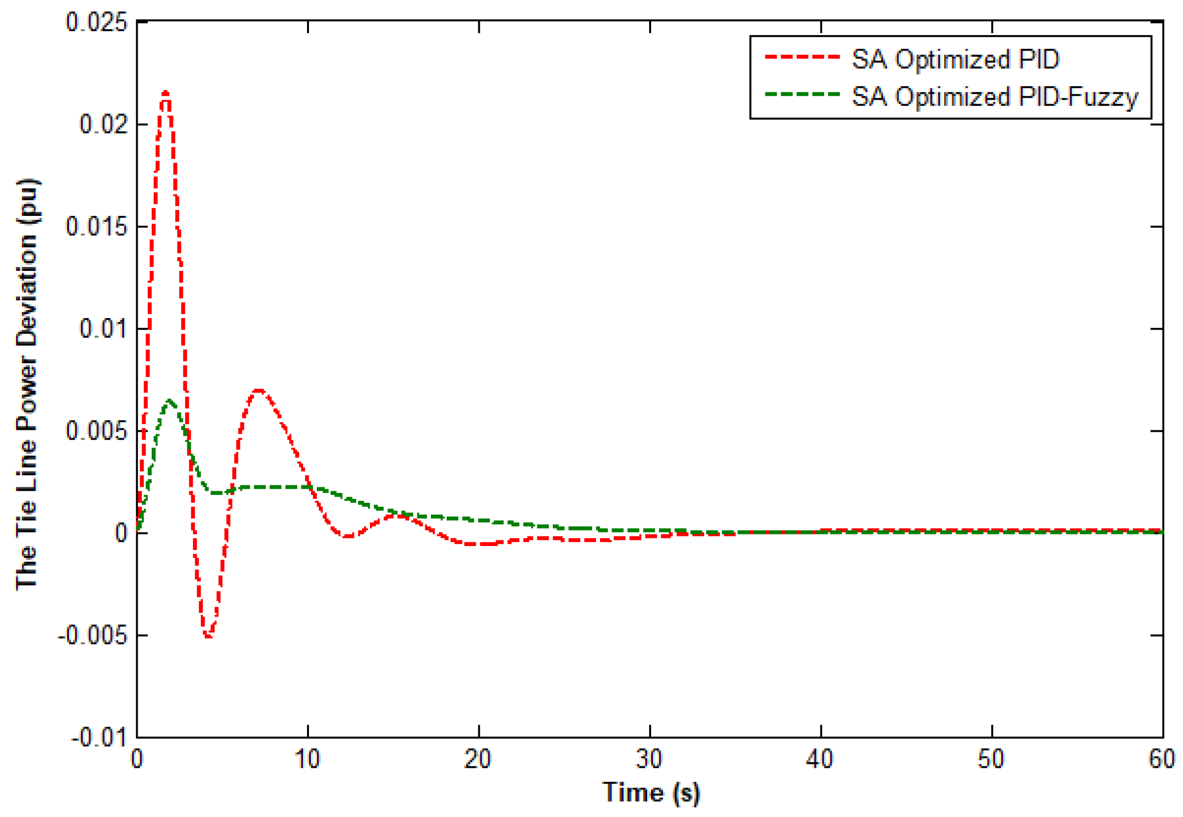
Additionally, Table 5 and Table 6 show that the PID–fuzzy controller performed better in terms of response. The settling time (ts) of PID–fuzzy controller was often less than that of a PID controller and had less overshoot by 60%. Furthermore, we found the proposed controller’s oscillation is appropriate for load frequency management. To check the dynamic performance of areas 1 and 2, we varied the time constants for the turbine and hydraulic amplifier for both areas and tried different input disturbances.
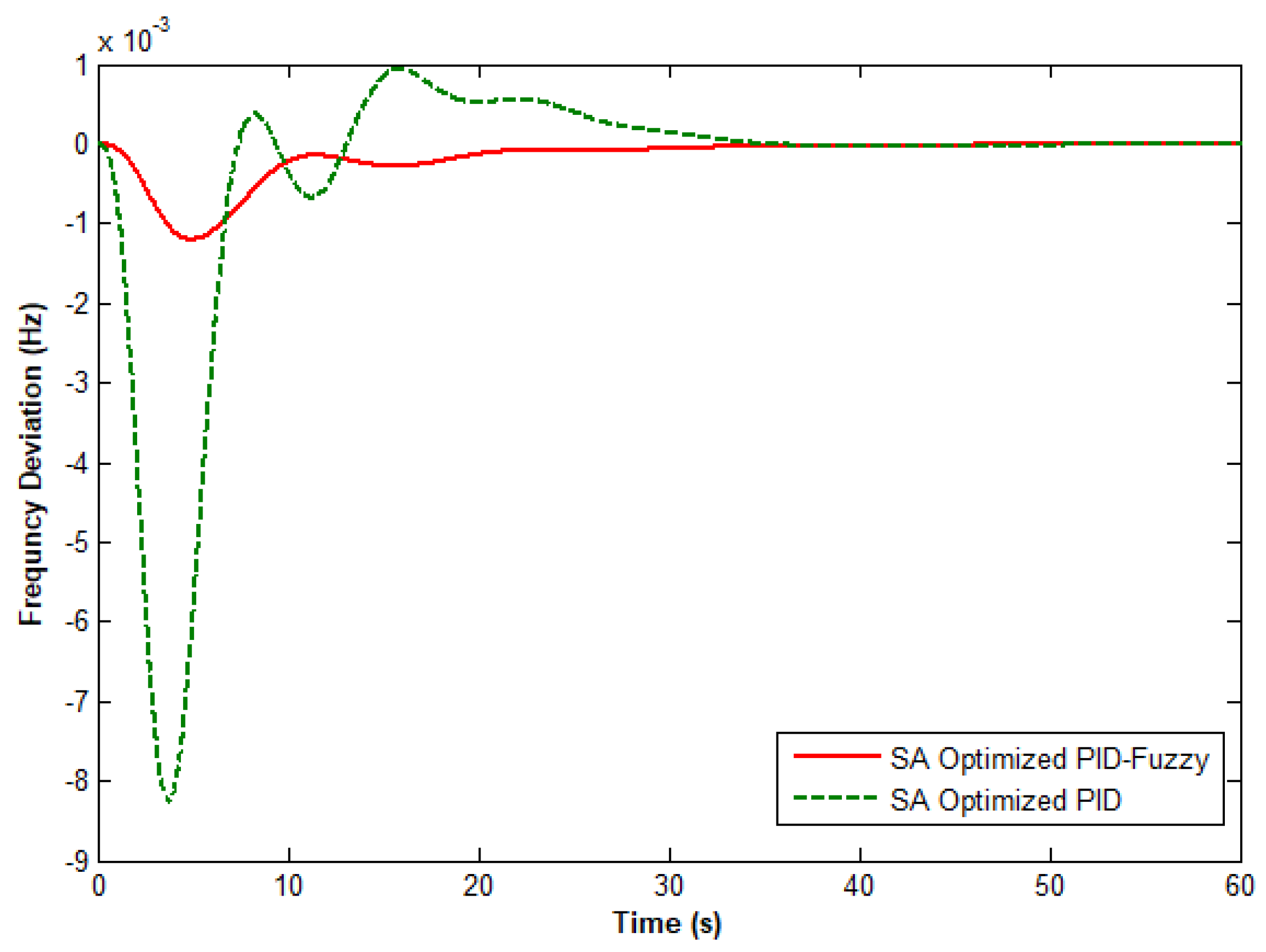
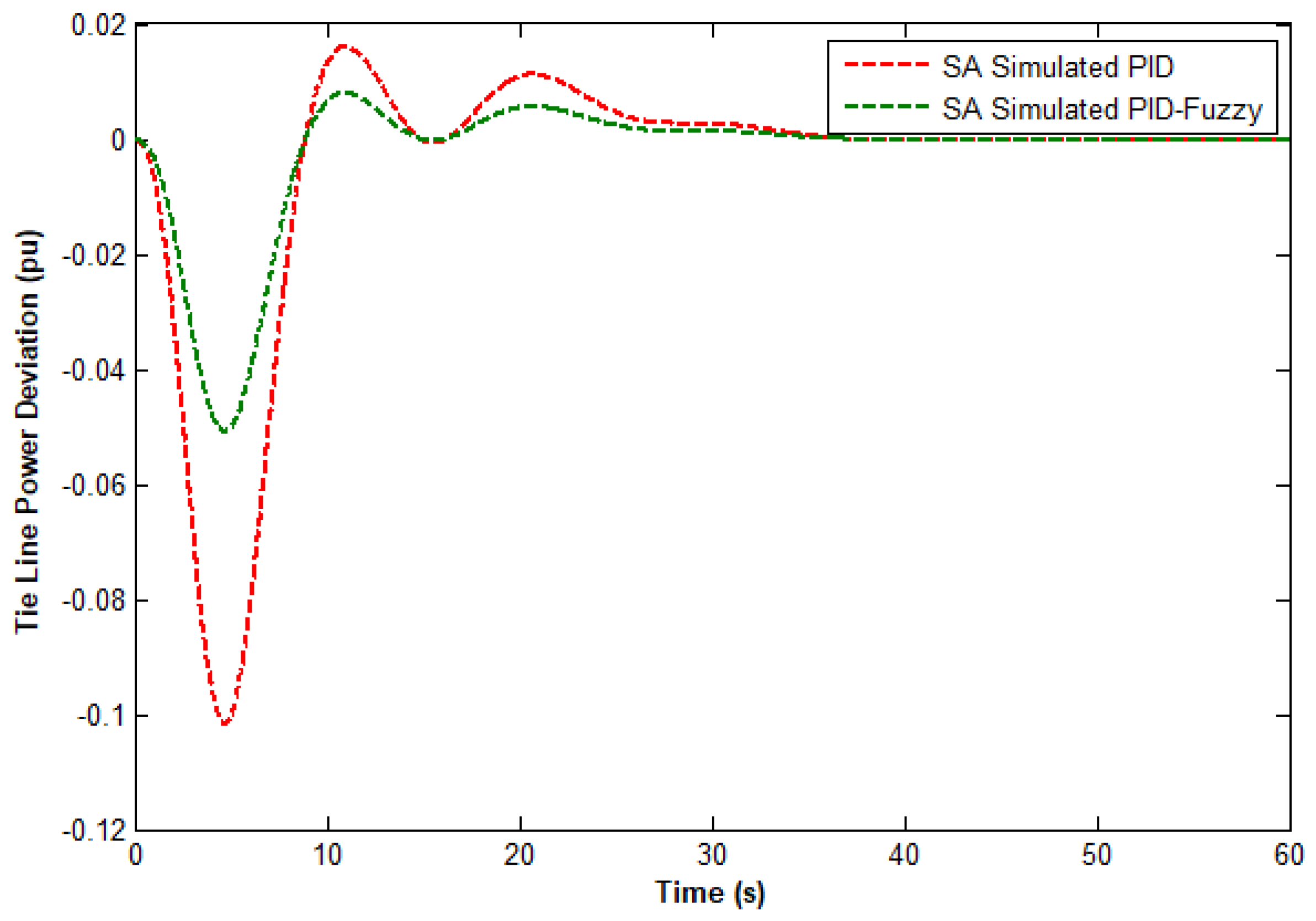
According to the first condition, the PID–fuzzy controller provides superior system response. The quality of a power source is determined by having a steady frequency, which is a hallmark of a reliable power supply. Regrading to the first case, the settling time as in Figure 7 was 26.328 for PID controller and 25.921 s for PID–fuzzy controller. In addition, the overshoot for areas-1 was very low as shown in Figure 7 is 0.00254 and in Figure 8 is 0.00078 Hz for area 2. Regarding power variations, the settling time of PID and PID–fuzzy controllers was 34.435 and 35.632 s, respectively; as depicted in Figure 9. Although the conventional PID controller is designed for specific operating points considering the linearized system model but With the proposed PID–fuzzy controller, the system performance can be improved because the fuzzy logic controller responds effectively to system nonlinearities and can cover a wide range of operating conditions. This is why the proposed hybrid system can accommodate complex dynamic-algebraic equations and system uncertainties. In the event of large load variations, both controllers may work separately or concurrently, but the hybrid PID–fuzzy-based controller is more stable.
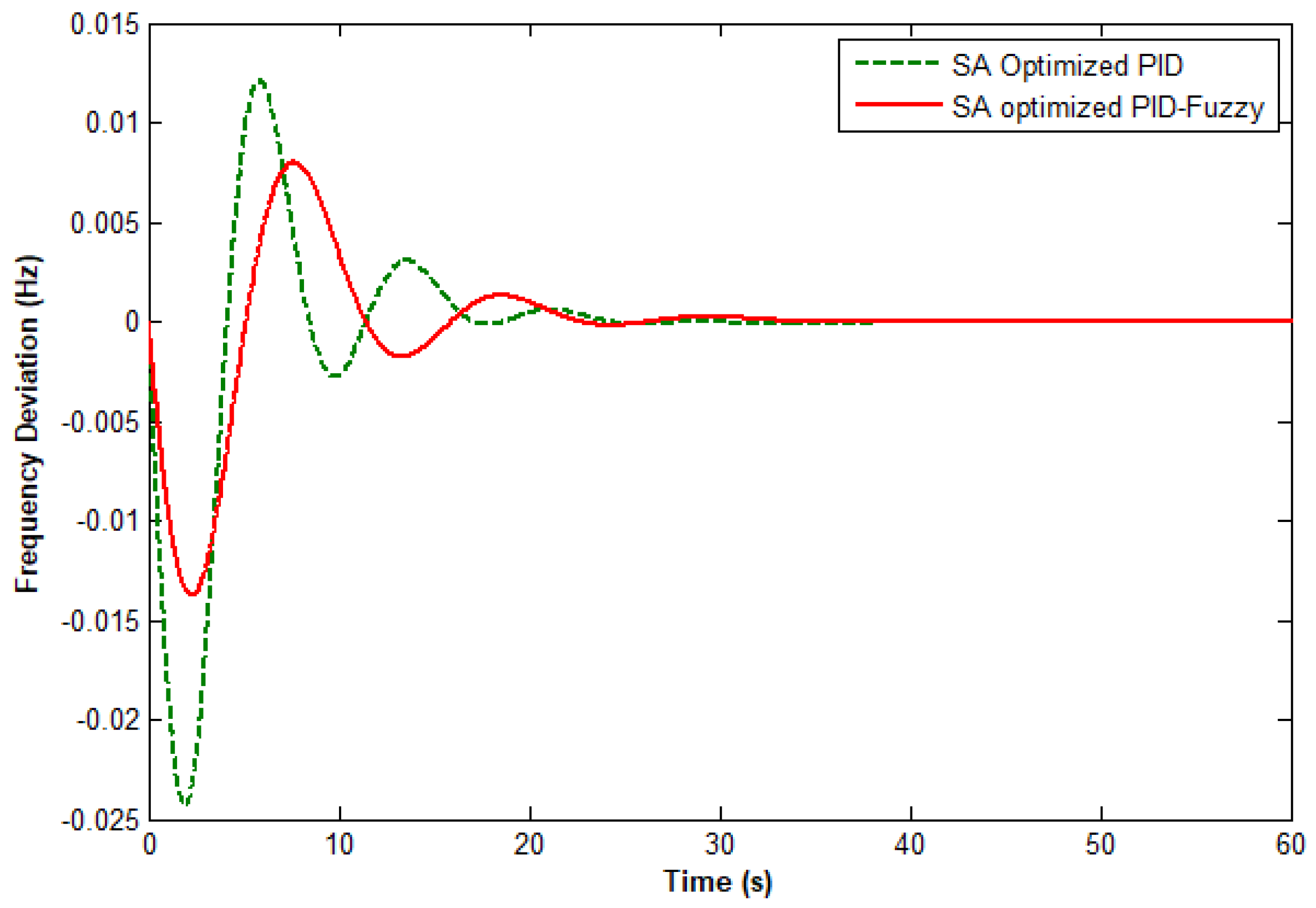
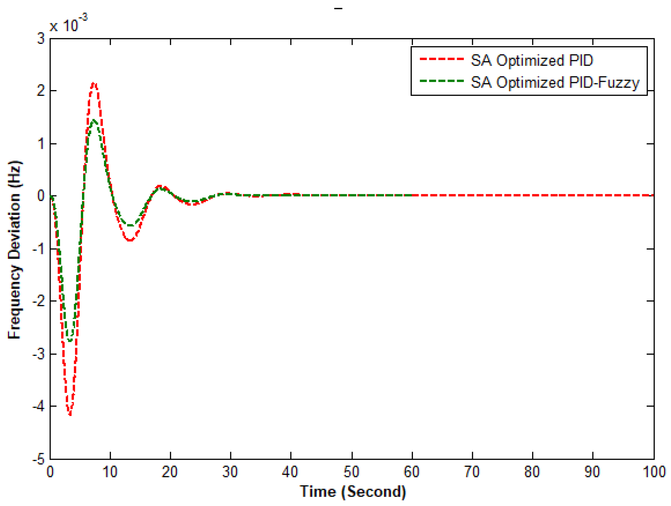
According to the second condition as results demonstrated in Figure 10, Figure 11 and Figure 12, the settling time for power deviations using PID and hybrid PID–fuzzy controllers was 36.351 in Figure 10 and 22.392 Figure 11, respectively. For both areas, the overshoot was very low: 0.00254 and 0.00078 Hz, respectively. The rise time was 3.012 and 3.013 s for in frequency deviations for areas 1 and 2, respectively.and lastly for power deviations is 4.922 as depicted in Figure 12. Additionally, in current power grids, electric loads are becoming more managed, and the rising penetration of renewable with power electronics, which minimizes the inertia of bulk power systems, necessitates the inclusion of fast dynamics in power system research and modeling. Finally, we double-checked our findings using multiple references from various authors as [15,17,21,23,28,33], and the results were excellent. However, because to space constraints, some articles do not provide sufficient details on how the results were produced, and others provided results by doing only single load disturbances and using a simple integrator with fixed parameters.

5. Conclusions

In this study, we considered the optimal automatic generation control for a two-area interconnected power system, and investigated step load disturbances. To dampen system frequency and tie-line power exchange variations, we proposed effective hybrid PID–fuzzy AGC based on the simulated annealing controller technique, instead of a conventional controller. The simulation results showed that the hybrid PID–fuzzy controller provides high stability and shows superior performance as compared to the PID controller. Future works include high contributions of renewable energy penetration considering dynamical behaviour described by a differential-algebric equation (DAE).

Author Contributions

Conceptualization, M.A.M.; methodology, M.A.M. and T.A.; software, M.A.M. and T.A.; validation, M.A.M. and T.A.; formal analysis, M.A.M. and T.A.; investigation, M.A.M. and T.A.; resources, M.A.M. and T.A.; data curation, M.A.M. and T.A.; writing—original draft preparation, M.A.M.; writing—review and editing, T.A.; supervision, T.A.; funding acquisition, T.A. All authors have read and agreed to the published version of the manuscript.

Funding

This project was funded by the Deanship of Scientific Research (DSR) at King Abdulaziz University, Jeddah, under grant number (G-564-135-438).

Institutional Review Board Statement

“Not applicable” for studies not involving humans or animals.

Informed Consent Statement

“Not applicable” for studies not involving humans.

Acknowledgments

The authors thanks Deanship of Scientific Research (DSR) at King Abdulaziz University for their technical and financial support.

Conflicts of Interest

The authors declare no conflict of interest.

References

  1. Sharma, Y.; Saikia, L.C. Automatic generation control of a multi-area ST—Thermal power system using Grey Wolf Optimizer algorithm based classical controllers. Int. J. Electr. Power Energy Syst. 2015, 73, 853–862. [Google Scholar] [CrossRef]
  2. Delassi, A.; Arif, S.; Mokrani, L. Load frequency control problem in interconnected power systems using robust fractional PIλ D controller. Ain Shams Eng. J. 2018, 9, 77–88. [Google Scholar] [CrossRef] [Green Version]
  3. Acharyulu, B.V.S.; Hota, P.K.; Mohanty, B. CLSA-MRPID controller for automatic generation control of a three-area hybrid system. Energy Syst. 2020, 11, 163–194. [Google Scholar] [CrossRef]
  4. Diggavi, K.C.; Pinnapureddy, R.; Rao, K.J. Analysis of load frequency control for multi area system using PI and fuzzy logic controllers. In Proceedings of the 2017 Second International Conference on Electrical, Computer and Communication Technologies (ICECCT), Coimbatore, India, 22–24 February 2017. [Google Scholar] [CrossRef]
  5. Roy, R.; Bhatt, P.; Ghoshal, S.P. Evolutionary computation based three-area automatic generation control. Expert Syst. Appl. 2010, 37, 5913–5924. [Google Scholar] [CrossRef]
  6. Raju, M.; Saikia, L.C.; Sinha, N. Automatic generation control of a multi-area system using ant lion optimizer algorithm based PID plus second order derivative controller. Int. J. Electr. Power Energy Syst. 2016, 80, 52–63. [Google Scholar] [CrossRef]
  7. Sala, A.; Albertos, P. Fuzzy Logic Controllers: Advantages and Drawbacks. Anales III. 1998. Available online: http://personales.upv.es/asala/publics/papers/c24alca98.pdf (accessed on 11 November 2021).
  8. Al-Odienat, A.I.; Al-Lawama, A.A. The advantages of PID fuzzy controllers over the conventional types. Am. J. Appl. Sci. 2008, 5, 653–658. [Google Scholar] [CrossRef] [Green Version]
  9. Bhandari, S.; Sahay, K.B.; Singh, R.K. Optimization Techniques in Modern Times and Their Applications. In Proceedings of the 2018 International Electrical Engineering Congress (iEECON), Krabi, Thailand, 7–9 March 2018. [Google Scholar] [CrossRef]
  10. Zhang, X.; Yu, T.; Pan, Z.; Yang, B.; Bao, T. Lifelong learning for complementary generation control of interconnected power grids with high-penetration renewable and EVs. IEEE Trans. Power Syst. 2018, 33, 4097–4110. [Google Scholar] [CrossRef]
  11. Zhang, X.; Xu, Z.; Yu, T.; Yang, B.; Wang, H. Optimal mileage based AGC dispatch of a GenCo. IEEE Trans. Power Syst. 2020, 35, 2516–2526. [Google Scholar] [CrossRef]
  12. Zhang, X.; Li, Q.; Yu, T.; Yang, B. Consensus transfer Q-learning for decentralized generation command dispatch based on virtual generation tribe. IEEE Trans. Smart Grid 2018, 9, 2152–2165. [Google Scholar] [CrossRef]
  13. Zhang, X.; Tan, T.; Zhou, B.; Yu, T.; Yang, B.; Huang, X. Adaptive distributed auction-based algorithm for optimal mileage based AGC dispatch with high participation of renewable energy. Int. J. Electr. Power Energy Syst. 2021, 124, 106371. [Google Scholar] [CrossRef]
  14. Rohini, V.; Natarajan, A.M. Comparison of genetic algorithm with Particle Swarm Optimisation, ant colony optimisation and Tabu search based on university course scheduling system. Indian J. Sci. Technol. 2016, 9. [Google Scholar] [CrossRef] [Green Version]
  15. Magdy, G.; Shabib, G.; Elbaset, A.A.; Mitani, Y. Optimized coordinated control of LFC and SMES to enhance frequency stability of a real multi-source power system considering high renewable energy penetration. Prot. Control Mod. Power Syst. 2018, 3, 39. [Google Scholar] [CrossRef] [Green Version]
  16. Hota, P.K.; Mohanty, B. Automatic generation control of multi source power generation under deregulated environment. Int. J. Electr. Power Energy Syst. 2016, 75, 205–214. [Google Scholar] [CrossRef]
  17. Daraz, A.; Malik, S.A.; Mokhlis, H.; Haq, I.U.; Laghari, G.F.; Mansor, N.N. Fitness Dependent Optimizer-Based Automatic Generation Control of Multi-Source Interconnected Power System with Non-Linearities. IEEE Access 2020, 8, 100989–101003. [Google Scholar] [CrossRef]
  18. Sahu, R.K.; Panda, S.; Rout, U.K.; Sahoo, D.K. Teaching learning based optimization algorithm for automatic generation control of power system using 2-DOF PID controller. Int. J. Electr. Power Energy Syst. 2016, 77, 287–301. [Google Scholar] [CrossRef]
  19. Ismail, M.M.; Bendary, A.F. Load Frequency Control for Multi Area Smart Grid based on Advanced Control Techniques. Alexandria Eng. J. 2018, 57, 4021–4032. [Google Scholar] [CrossRef]
  20. Falehi, A.D. Optimal design of fuzzy-AGC based on PSO & RCGA to improve dynamic stability of interconnected multi area power systems. Int. J. Autom. Comput. 2017, 17, 599–609. [Google Scholar] [CrossRef]
  21. Alzaareer, K.; Al-Shetwi, A.Q.; El-Bayeh, C.Z.; Taha, M.B. Automatic generation control of multi-area interconnected power systems using ANN controller. Rev. D’Intell. Artif. 2020, 34, 1–10. [Google Scholar] [CrossRef]
  22. Dhillon, S.S.; Lather, J.S.; Marwaha, S. Multi Area Load Frequency Control Using Particle Swarm Optimization and Fuzzy Rules. Procedia Comput. Sci. 2015, 57, 460–472. [Google Scholar] [CrossRef] [Green Version]
  23. Sahu, R.K.; Rout, U.K.; Panda, S. Automatic generation control of multi-area power system using gravitational search algorithm. In Lecture Notes in Computer Science; 8297 LNCS, no. PART 1; Springer: Cham, Switzerland, 2013. [Google Scholar] [CrossRef]
  24. Sambariya, D.; Nath, V. Load Frequency Control Using Fuzzy Logic Based Controller for Multi-area Power System. Br. J. Math. Comput. Sci. 2016, 13, 1–19. [Google Scholar] [CrossRef]
  25. Arya, Y.; Kumar, N. Optimal control strategy–based AGC of electrical power systems: A comparative performance analysis. Optim. Control. Appl. Methods 2017, 38, 982–992. [Google Scholar] [CrossRef]
  26. Ajithapriyadarsini, S.; Mary, P.M.; Iruthayarajan, M.W. Automatic generation control of a multi-area power system with renewable energy source under deregulated environment: Adaptive fuzzy logic-based differential evolution (DE) algorithm. Soft Comput. 2019, 23, 12087–12101. [Google Scholar] [CrossRef]
  27. Jagatheesan, K.; Anand, B. Performance analysis of three area thermal power systems with different steam system configurations considering non linearity and boiler dynamics using conventional controller. In Proceedings of the 2015 International Conference on Computer Communication and Informatics (ICCCI), Coimbatore, India, 8–10 January 2015. [Google Scholar] [CrossRef]
  28. Fathy, A.; Kassem, A.M.; Abdelaziz, A.Y. Optimal design of fuzzy PID controller for deregulated LFC of multi-area power system via mine blast algorithm. Neural Comput. Appl. 2020, 32, 4531–4551. [Google Scholar] [CrossRef]
  29. Demiroren, A.; Yesil, E. Automatic generation control with fuzzy logic controllers in the power system including SMES units. Int. J. Electr. Power Energy Syst. 2004, 26, 291–305. [Google Scholar] [CrossRef]
  30. Abo-Elyousr, F.K. Load frequency controller design for two area interconnected power system with DFIG based wind turbine via ant colony algorithm. In Proceedings of the 2016 Eighteenth International Middle East Power Systems Conference (MEPCON), Cairo, Egypt, 27–29 December 2016. [Google Scholar] [CrossRef]
  31. John, N.; Ramesh, K. Enhancement of Load Frequency Control Considerning High Penetration of Wind Turbine using PSO-Fuzzy Technique. Int. J. Comput. Appl. 2013, 69, 1–7. [Google Scholar] [CrossRef]
  32. Rakhshani, E.; Rouzbehi, K.; Sadeh, S. A new combined model for simulation of mutual effects between LFC and avr loops. In Proceedings of the 2009 Asia-Pacific Power and Energy Engineering Conference, Wuhan, China, 27–31 March 2009. [Google Scholar] [CrossRef]
  33. Mishra, E.; Tiwari, S. Comparative Analysis of Fuzzy Logic and PI Controller Based Electronic Load Controller for Self-Excited Induction Generator. Adv. Electr. Eng. 2017, 2017, 5620830. [Google Scholar] [CrossRef] [Green Version]
  34. Panda, G.; Panda, S.; Cemal, A. Automatic generation control of interconnected power system with generation rate constraints by hybrid neuro fuzzy approach. Int. J. Electr. Electron. Eng. 2009, 6, 471–476. [Google Scholar]
  35. Saikia, L.C. AGC of a three area thermal system using MLPNN controller: A preliminary study. In Proceedings of the 2012 9th International Conference on Electrical Engineering/Electronics, Computer, Telecommunications and Information Technology, Phetchaburi, Thailand, 16–18 May 2012. [Google Scholar]
  36. Ahmed, M.; Osman, M.; Magzoub, A.; Salem, A. Load Frequency Control in Two Area Power System using GA, SA and PSO Algorithms: A Comparative Study. In Proceedings of the 2021 31st Australasian Universities Power Engineering Conference (AUPEC), Perth, Australia, 26–30 September 2021. [Google Scholar]
  37. Saikia, L.C.; Nanda, J.; Mishra, S. Performance comparison of several classical controllers in AGC for multi-area interconnected thermal system. Int. J. Electr. Power Energy Syst. 2011, 33, 394–401. [Google Scholar] [CrossRef]
Figure 1. AGC components and connection to power generation.
Energies 15 01540 g001
Figure 2. Simulink AGC components for two-area power system.
Energies 15 01540 g002
Figure 3. The pseudocode of simulated annealing (SA).
Energies 15 01540 g003
Figure 4. Flow chart of the simulated annealing optimization approach.
Energies 15 01540 g004
Figure 5. Proposed hybrid PID–fuzzy-based controller.
Energies 15 01540 g005
Figure 6. Membership functions of fuzzy logic.
Energies 15 01540 g006
Figure 7. Frequency deviations in area 1 for the first case.
Energies 15 01540 g007
Figure 8. Frequency deviations in area 2 for the first case.
Energies 15 01540 g008
Figure 9. Tie-line power deviations for the first case.
Energies 15 01540 g009
Figure 10. Frequency deviations in area 1 for the second case.
Energies 15 01540 g010
Figure 11. Frequency deviations in area 2 for the second case.
Energies 15 01540 g011
Figure 12. Tie-line power deviations for the second case.
Energies 15 01540 g012
Table 1. SA parameters.
Max iterationsInfMax function evaluations12,000
Time limitInfFunction tolerance1 × 10 6
Objective limitInfStall iterations2000
Annealing functionFast annealingReannealing interval100
Table 2. Rule bases of the proposed method.
ACE
ΔACEHNMNLNZLPMPHP
HNHPHPHPMPMPLPZ
MNHPMPLPLPZLNMN
LNHPLPZLNLNMNHN
ZMPMPLPZLNMNMN
LPHPLPZLNLNMNHN
MPLPZLNMNMNMNHN
HPZLNMNMNHNHNHN
HP: high positive, LP: low positive, HN: high negative, LN: low negative; Z: zero, MN: medium negative, MP: medium positive.
Table 3. System Parameters.
ParameterArea 1Area 2
Speed regulation R 1 = 0.05 R 2 = 0.0625
Frequency dependency of load D 1 = 0.6 D 1 = 0.9
Inertial constantH = 5H = 4
Base power1000 MVA1000 MVA
Governor time constant T t 1 = 0.2 s T t 2 = 0.3 s
Turbine time constant T h 1 = 0.5 s T h 2 = 0.6 s
Synchronization coefficient T o = 1 / π
Table 4. System-tuned variables.
Interconnected AreaOptimum ParametersSA-Tuned
Area 1 B 1 28.1295
K P 1.7928
K I 1.9747
K D 0.6572
Area 2 B 2 6.1128
K P 1.9999
K I 1.7010
K D 0.8333
Table 5. Case 1: Dynamic performance characteristics of the two controllers for a 0.2 pu change in area 1.
Δ f 1 Δ f 2 Δ P tie , 12
ParameterPIDPID–FuzzyPIDPID–FuzzyPIDPID-Fuzzy
T P 3.0123.0133.0113.02314.0564.043
T s 26.32825.92136.64233.65134.43535.632
M p 0.002540.000780.000820.0013530.1340.04921
Tp: peak time, Ts: settling time, and Mp: peak amplitude.
Table 6. Case 2: dynamic performance characteristics of the two controllers for a 0.2 pu change in area 2.
Δ f 1 Δ f 2 Δ P tie , 12
ParameterPIDPID–FuzzyPIDPID–FuzzyPIDPID–Fuzzy
T P 2.6542.6732.9652.7823.7653.552
T s 26.32124.73227.54327.44636.35122.392
M p 0.02480..01480.00420.00280.02360.0073
Tp: peak time, Ts: settling time, and Mp: peak amplitude.
Publisher’s Note: MDPI stays neutral with regard to jurisdictional claims in published maps and institutional affiliations.