
Design, Energy, Environmental and Cost Analysis of an Integrated Collector Storage Solar Water Heater Based on Multi-Criteria Methodology

 , ,
, ,  ,
,  ,
,  , and
, and 
Abstract
:1. Introduction
2. Design, Energy, and Environmental Analysis
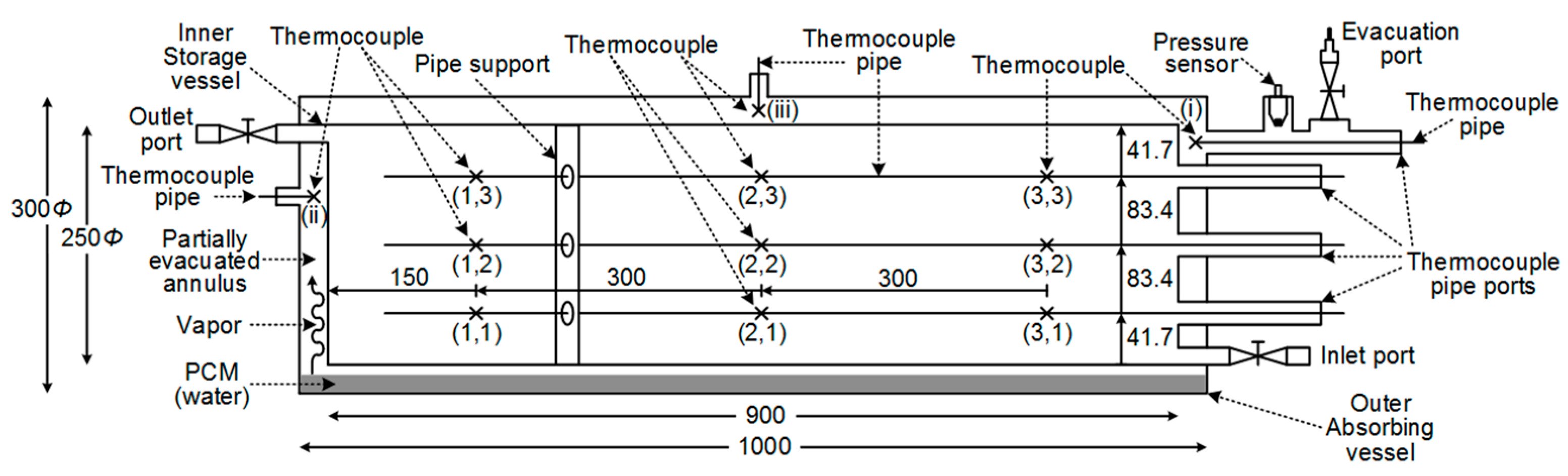
2.1. Design and Operation Concept of the ICS System
2.2. Environmental and Energy Analysis during Fabrication and Installation Phases
2.3. Energy, Environmental and Economic Analysis in Operation Mode
- QTHE⁄Year: produced thermal energy, in MWh/Year
- A: absorbing surface, in m2
- Gm: mean daily solar radiation on the aperture plane, in W/m2
- ηd (ψm, φm, B, C): mean daily efficiency for the time period t of the day
- US (D, F): thermal loss coefficient during night operation, in W·m−2·K−1
- Ti,m: mean initial water temperature during night operation, in °C
- Τα,m: mean ambient temperature during night operation, in °C
- DΚ: number of days of each month
- k: an index for each month for one-year operation period of the system
- Ct: net cash inflow during the period t
- Co: total initial investment costs
- r: discount rate
- t: number of time periods.
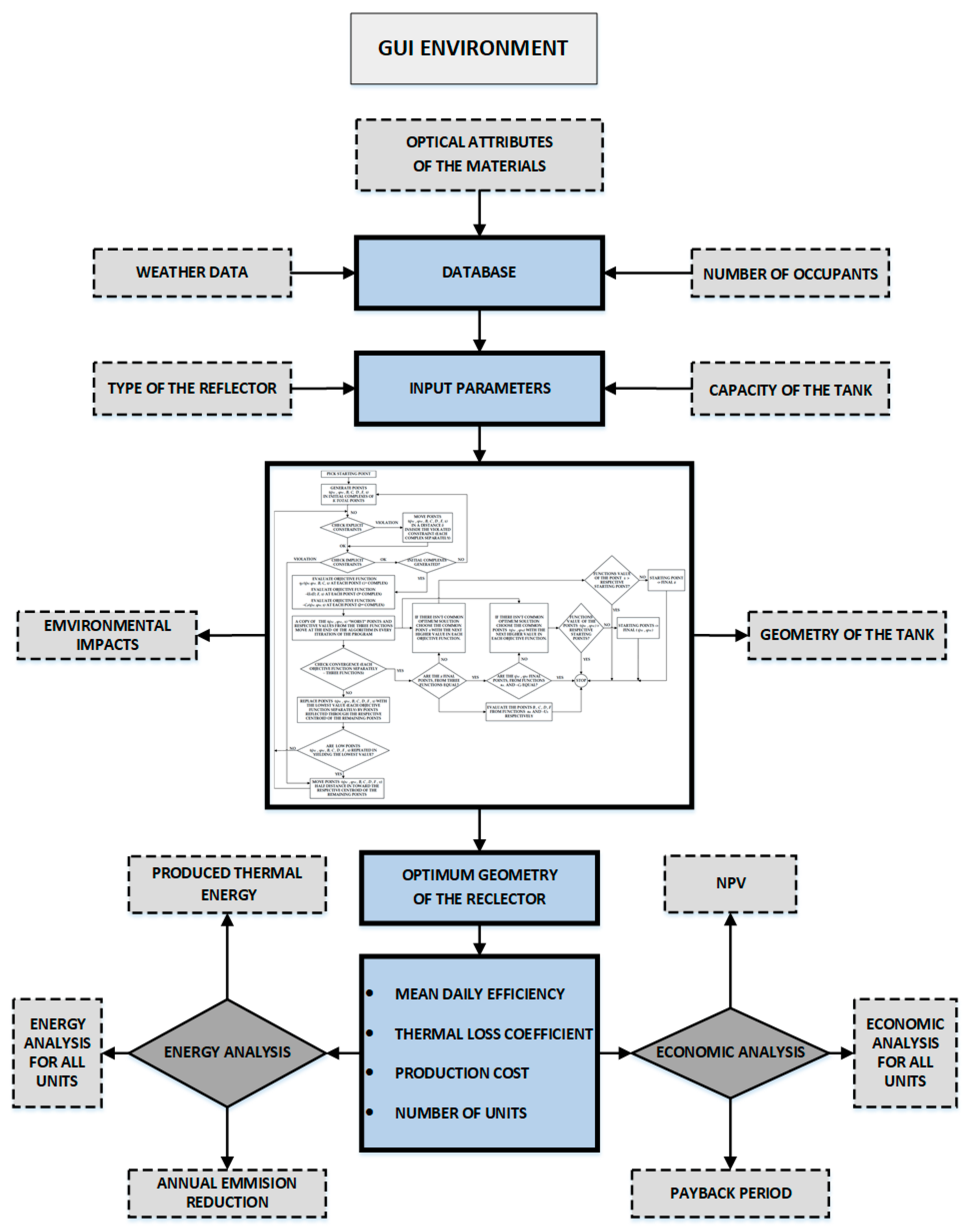
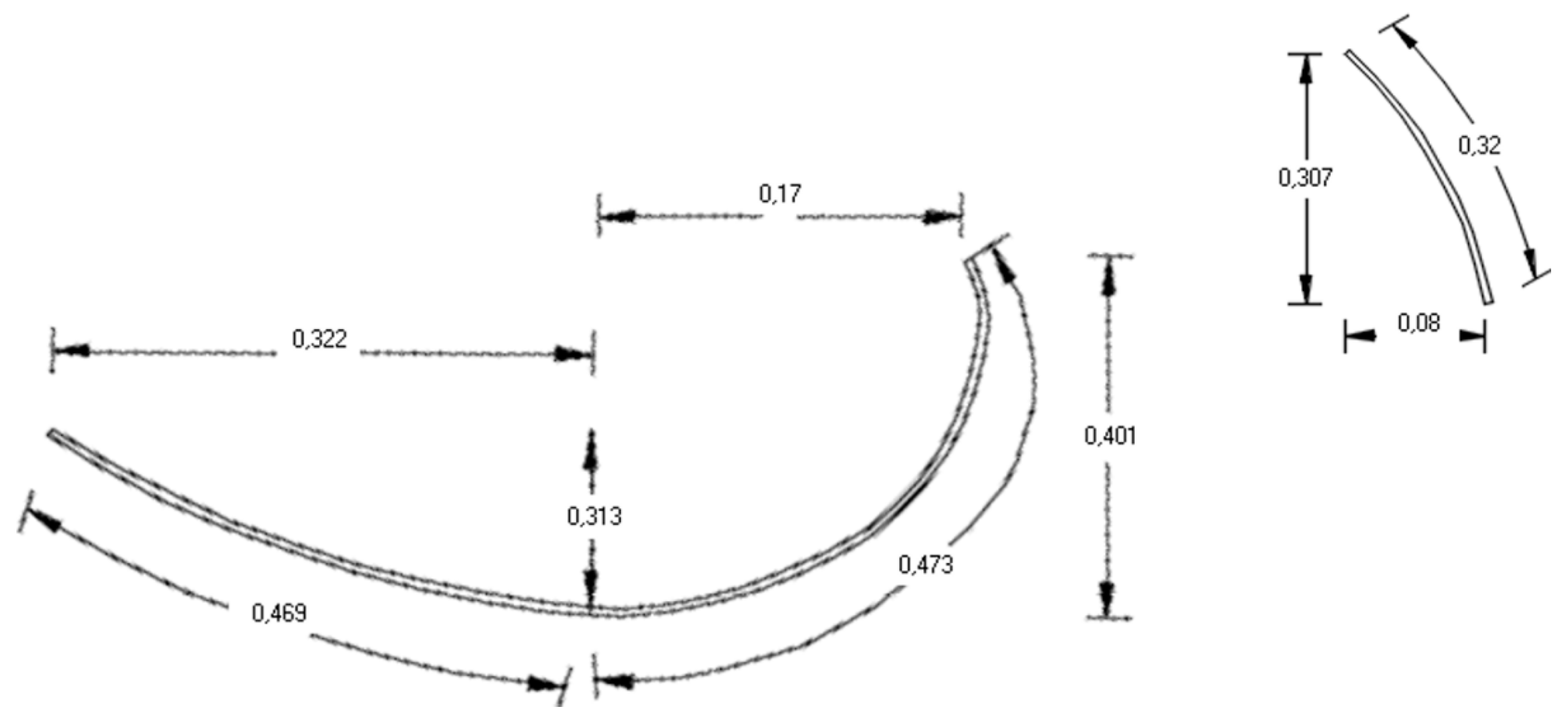
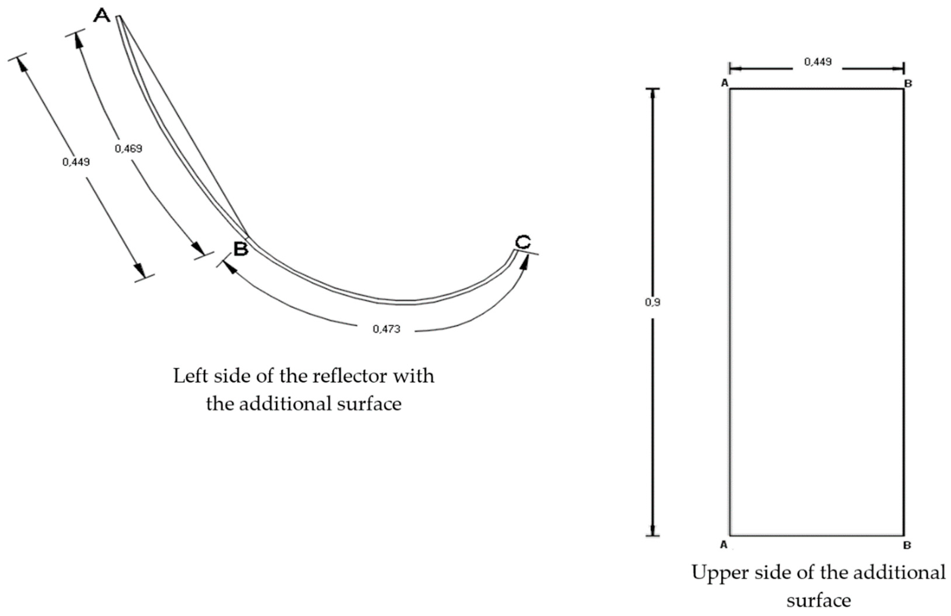
2.4. Design Analysis
- + + +: Environmentally friendly materials.
- − + +: Materials with more pollutants but not very harmful to the environment.
- − − +: Less environmentally friendly materials.
- − − −: Materials with damaging environmental behavior.
- The energy analysis option, which calculates the produced thermal energy during the entire life cycle of the system and is accompanied by the evaluation of the annual emission reduction during its operation.
- The economic analysis choice, which can provide information about the profit of the investment.
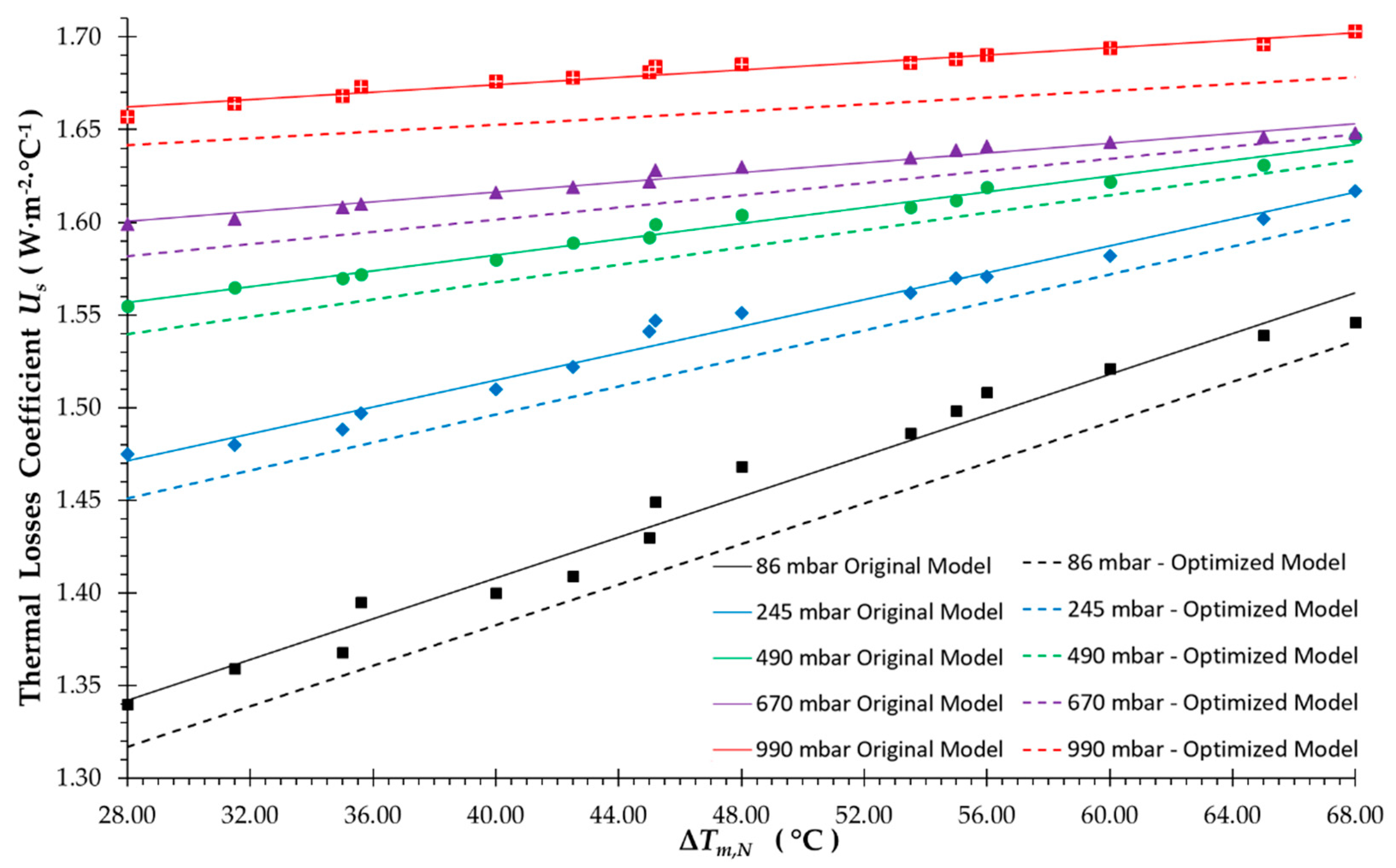
- 86 ± 2 mbar (at 19.5 ± 1 °C)
- 245 ± 6 mbar (at 24.0 ± 1 °C)
- 490 ± 11 mbar (at 23.0 ± 1 °C)
- 670 ± 16 mbar (at 22.0 ± 1 °C)
- 990 ± 23 mbar (at 24 ± 1 °C)
3. Results
4. Conclusions
Author Contributions
Funding
Institutional Review Board Statement
Informed Consent Statement
Conflicts of Interest
References
- Souliotis, M.; Tripanagnostopoulos, Y. Study of the distribution of the absorbed solar radiation on the performance of a CPC-type ICS water heater. Renew. Energy 2008, 33, 846–858. [Google Scholar] [CrossRef]
- Tripanagnostopoulos, Υ.; Souliotis, M.; Nousia, T. CPC type integrated collector storage systems. Sol. Energy 2002, 72, 327–350. [Google Scholar] [CrossRef]
- O’Gallagher, J.J.; Snail, K.; Winston, R.; Peek, C.; Garrison, J.D. A new evacuated CPC collector tube. Sol. Energy 1982, 29, 575–577. [Google Scholar] [CrossRef]
- Souliotis, M.; Singh, R.; Papaefthimiou, S.; Lazarus, I.J.; Andriosopoulos, K. Integrated collector storage solar water heaters: Survey and recent developments. Energy Syst. 2016, 7, 49–72. [Google Scholar] [CrossRef]
- Singh, R.; Lazarus, I.J.; Souliotis, M. Recent developments in integrated collector storage (ICS) solar water heaters: A review. Renew. Sust. Energy Rev. 2016, 54, 270–298. [Google Scholar] [CrossRef]
- Papaefthimiou, S.; Zopounidis, C.; Andriosopoulos, K. Editorial for the Special Issue: Recent developments in energy modeling and management. Energy Syst. 2016, 7, 1–4. [Google Scholar] [CrossRef] [Green Version]
- Crawford, R.H.; Treloar, G.J.; Ilozor, B.D.; Love, P.E.D. Comparative greenhouse emissions analysis of domestic solar hot water systems. Build. Res. Inf. 2003, 31, 34–47. [Google Scholar] [CrossRef] [Green Version]
- Kalogirou, S.A. Thermal performance, economic and environmental life cycle analysis of thermosiphon solar water heaters. Sol. Energy 2009, 83, 39–48. [Google Scholar] [CrossRef]
- Hang, Y.; Qu, M.; Zhao, F. Economic and environmental life cycle analysis of solar hot water systems in the United States. Energy Build. 2012, 45, 181–188. [Google Scholar] [CrossRef]
- Colle, S.; De Abreu, S.L.; Rüther, R. Uncertainty in economical analysis of solar water heating and photovoltaic systems. Sol. Energy 2001, 70, 131–142. [Google Scholar] [CrossRef]
- Ardente, F.; Beccali, G.; Cellura, M.; Lo Brano, V. Life cycle assessment of a solar thermal collector. Renew. Energy 2005, 30, 1031–1054. [Google Scholar] [CrossRef]
- Crawford, R.H.; Treloar, G.J. Net energy analysis of solar and conventional domestic hot water systems in Melbourne, Australia. Sol. Energy 2004, 76, 159–163. [Google Scholar] [CrossRef] [Green Version]
- Jankura, A.; Sekret, R. Life cycle assessment of the use of phase change material in an evacuated solar tube collector. Energies 2021, 14, 4146. [Google Scholar]
- Karasu, H.; Dincer, I. Life cycle assessment of integrated thermal energy storage systems in buildings: A case study in Canada. Energy Build. 2021, 217, 109940. [Google Scholar] [CrossRef]
- Lamnatou, C.; Chemisana, D. Concentrating solar systems: Life Cycle Assessment (LCA) and environmental issues. Renew. Sust. Energy Rev. 2017, 78, 916–932. [Google Scholar] [CrossRef] [Green Version]
- Lamnatou, C.; Cristofari, C.; Chemisana, D.; Canaletti, J.L. Building-integrated solar thermal systems based on vacuum-tube technology: Critical factors focusing on life-cycle environmental profile. Renew. Sust. Energy Rev. 2016, 65, 1199–1215. [Google Scholar] [CrossRef] [Green Version]
- Lamnatou, C.; Motte, F.; Notton, G.; Chemisana, D.; Cristofari, C. Cumulative energy demand and global warming potential of a building-integrated solar thermal system with/without phase change material. J. Environ. Manag. 2018, 212, 301–310. [Google Scholar] [CrossRef] [Green Version]
- Hobson, P.A.; Norton, B. A design nomogram for direct thermosyphon solar-energy water heaters. Sol. Energy 1989, 43, 85–95. [Google Scholar] [CrossRef]
- Gordon, J.M.; Rabl, A. Design, analysis and optimization of solar industrial process heat plants without storage. Sol. Energy 1982, 28, 519–530. [Google Scholar] [CrossRef]
- Frei, U.; Vogelsanger, P. Solar Thermal Systems for Domestic Hot Water and Space Heating. Report of SPF Institut für Solartechnik Prüfung Forschung. 2000, pp. 1–12. Available online: https://www.researchgate.net/publication/238741144_SOLAR_THERMAL_SYSTEMS_FOR_DOMESTIC_HOT_WATER_AND_SPACE_HEATING (accessed on 8 January 2022).
- Lund, P.D.; Peltola, S.S. SOLCHIPS-A fast predesign and optimization tool for solar heating with seasonal storage. Sol. Energy 1992, 48, 291–300. [Google Scholar] [CrossRef]
- Abdel-Malek, L. Optimum design of solar water heating systems. Comput. Oper. Res. 1985, 12, 219–225. [Google Scholar] [CrossRef]
- De Winter, F. Optimum Designs for Solar Water Heating Equipment for the Single Family Home. In Proceedings of the +IV Conferencia Latino Americana de Energía Solar (IV ISES CLA) y XVII Simposio Peruano de Energía, Cusco, Peru, 1–5 November 2010. [Google Scholar]
- Ko, M.J. Analysis and Optimization Design of a Solar Water Heating System Based on Life Cycle Cost Using a Genetic Algorithm. Energies 2015, 8, 11380–11403. [Google Scholar] [CrossRef] [Green Version]
- Patrčević, F.; Dović, D.; Horvat, I.; Filipović, P. A Novel Dynamic Approach to Cost-Optimal Energy Performance Calculations of a Solar Hot Water System in an nZEB Multi-Apartment Building. Energies 2022, 15, 509. [Google Scholar] [CrossRef]
- Souliotis, M.; Quinlan, P.; Smyth, M.; Tripanagnostopoulos, Y.; Zacharopoulos, A.; Ramirez, M.; Yianoulis, P. Heat retaining integrated collector storage solar water heater with asymmetric CPC reflector. Sol. Energy 2011, 85, 2474–2487. [Google Scholar] [CrossRef]
- Souliotis, M.; Papaefthimiou, S.; Caouris, Y.G.; Zacharopoulos, A.; Quinlan, P.; Smyth, M. Integrated collector storage solar water heater under partial vacuum. Energy 2017, 139, 991–1002. [Google Scholar] [CrossRef]
- Haillot, D.; Py, X.; Goetz, V.; Benabdelkarim, M. Storage composites for the optimisation of solar water heating systems. Chem. Eng. Res. Des. 2008, 86, 612–617. [Google Scholar] [CrossRef]
- Eames, P.C.; Griffiths, P.W. Thermal behaviour of integrated solar collector/storage unit with 65 °C phase change material. Energy Convers. Manag. 2006, 47, 3611–3618. [Google Scholar] [CrossRef]
- Al-Hinti, I.; Al-Ghandoor, A.; Maaly, A.; Abu Naqeera, I.; Al-Khateeb, Z.; Al-Sheikh, O. Experimental investigation on the use of water-phase change material storage in conventional solar water heating systems. Energy Convers. Manag. 2010, 51, 1735–1740. [Google Scholar] [CrossRef]
- Chaabane, M.; Mhiri, H.; Bournot, P. Thermal performance of an integrated collector storage solar water heater (ICSSWH) with phase change materials (PCM). Energy Convers. Manag. 2014, 78, 897–903. [Google Scholar] [CrossRef]
- De Beijer, H.A. Product development in solar water heating. Renew. Energy 1998, 15, 201–204. [Google Scholar] [CrossRef]
- Pugsley, A.; Smyth, M.; Mondol, J.D.; Zacharopoulos, A.; Di Mattia, L. Experimental Characterisation of a Flat Panel Integrated-Collector-Storage Solar Water Heater Featuring a Photovoltaic Absorber and a Planar Liquid-Vapour Thermal Diode. In Proceedings of the 11th EuroSun 2016, Palma, Spain, 11–14 October 2016; pp. 1–12. [Google Scholar]
- Rhee, J.; Campbell, A.; Mariadass, A.; Morhous, B. Temperature stratification from thermal diodes in solar hot water storage tank. Sol. Energy 2010, 84, 507–511. [Google Scholar] [CrossRef]
- Arnaoutakis, N.; Souliotis, M.; Papaefthimiou, S. Comparative experimental Life Cycle Assessment of two commercial solar thermal devices for domestic applications. Renew. Energy 2017, 111, 187–200. [Google Scholar] [CrossRef]
- ISO 14040:2006; Environmental Management—Life Cycle Assessment—Principles and Framework. ISO: Geneva, Switzerland, 2006. Available online: https://www.iso.org/standard/37456.html (accessed on 8 January 2022).
- ISO 14044:2006; Environmental Management—Life Cycle Assessment—Requirements and Guidelines. ISO: Geneva, Switzerland, 2006. Available online: https://www.iso.org/standard/38498.html (accessed on 8 January 2022).
- SimaPro. The World’s Leading LCA Software. Available online: https://simapro.com/ (accessed on 8 January 2022).
- Ecoinvent. Available online: https://www.ecoinvent.org/ (accessed on 8 January 2022).
- Agency for Toxic Substances and Disease Registry. Available online: https://www.atsdr.cdc.gov/ (accessed on 8 January 2022).
- Souliotis, M.; Tripanagnostopoulos, Y. Experimental study of CPC type ICS solar systems. Sol. Energy 2004, 76, 389–408. [Google Scholar] [CrossRef]
- Engineering ToolBox. Available online: https://www.engineeringtoolbox.com/ (accessed on 8 January 2022).
- Rabl, A. Solar concentrators with maximal concentration for cylindrical absorbers. Appl. Opt. 1976, 15, 1871. [Google Scholar] [CrossRef]
- Arnaoutakis, N.; Milousi, M.; Papaefthimiou, S.; Fokaides, P.A.; Caouris, Y.G.; Souliotis, M. Life cycle assessment as a methodological tool for the optimum design of integrated collector storage solar water heaters. Energy 2019, 182, 1084–1099. [Google Scholar] [CrossRef]
- RETScreen. Natural Resources Canada. Available online: https://www.nrcan.gc.ca/maps-tools-publications/tools/data-analysis-software-modelling/retscreen/7465 (accessed on 8 January 2022).
- Lin, G.C.I.; Nagalingam, S.V. CIM Justification and Optimisation; Taylor & Francis; CRC Press: London, UK, 2000. [Google Scholar]
- Khan, M.Y. Theory and Problems in Financial Management. Available online: https://www.bookdepository.com/Theory-Problems-Financial-Management-M-Y-Khan/9780074636831 (accessed on 8 January 2022).
- William, W.A.; Deren, B.J.; D’Silva, E.H. The Economics of Project Analysis: A Practitioner’s Guide; Economic Development Institute of the World Bank, World Bank Publications: Washington, DC, USA, 1991. [Google Scholar]
- Tripanagnostopoulos, Y.; Souliotis, M. Integrated collector storage solar Systems with asymmetric CPC reflectors. Renew. Energy 2004, 29, 223–248. [Google Scholar] [CrossRef]
- Schaum’s Mathematical Handbook of Formulas And tables. Available online: https://epdf.pub/schaums-mathematical-handbook-of-formulas-and-tablesdc2f8603272491941b362853bbce940385159.html (accessed on 8 January 2022).
- McCleary, J. Geometry from a Differentiable Viewpoint; Cambridge University Press: Cambridge, UK, 2012. [Google Scholar]
- Kuester, J.L.; Mize, J.H. Optimization Techniques with Fortran; Mc Graw-Hill: New York, NY, USA, 1973. [Google Scholar]
- Spendley, W.; Hext, G.R.; Himsworth, F.R. Sequential Application of Simplex Designs in Optimisation and Evolutionary Operation. Technometrics 1962, 4, 441. [Google Scholar] [CrossRef]
- AAMA-Glass Standards and Guidelines. Available online: https://aamanet.org/pages/glass-standards-and-guidelines (accessed on 8 January 2022).
- Materials Science and Engineering. MIT Open Course Ware. Free Online Course Materials. Available online: https://ocw.mit.edu/courses/materials-science-and-engineering/ (accessed on 8 January 2022).
- Plasticker-The Home of Plastics. Available online: https://plasticker.de/ (accessed on 8 January 2022).
- Velmurugan, V.; Srithar, K. Prospects and scopes of solar pond: A detailed review. Renew. Sust. Energy Rev. 2008, 12, 2253–2263. [Google Scholar] [CrossRef]
- Review of Solar Radiation Estimation and Solar Data Banks Elaboration Methodologies over Greece. Available online: https://www.researchgate.net/publication/230710390_Review_of_Solar_Radiation_estimation_and_Solar_Data_Banks_elaboration_methodologies_over_Greece (accessed on 8 January 2022).


| Absorbing Reflector | Water Tank | Other Parts | |||
|---|---|---|---|---|---|
| Material | Mass (kg) | Material | Mass (kg) | Material | Mass (kg) |
| Steel | 44.47 | Steel | 29.40 | Plastic tube | 2 |
| Aluminium | 6.49 | Magnesium | 0.10 | Glass fibre | 2 |
| Solar Glass | 8.74 | ||||
| PUR | 12.02 | ||||
| Total | 71.72 | 29.50 | 4 | ||
| Cases for Initial Pressure (in mbar) | Fabrication Costs (Euros) | Cost Differences (€) | |
|---|---|---|---|
| Optimized ICS Unit | Reference ICS Unit | ||
| 990 ± 23 | 210.74 | 255.12 | 44.38 |
| 670 ± 16 | 208.98 | 255.12 | 46.14 |
| 490 ± 11 | 207.00 | 255.12 | 48.12 |
| 245 ± 6 | 202.45 | 255.12 | 52.67 |
| 86 ± 2 | 195.12 | 255.12 | 60.00 |
| Systems | Number of ICS Units | Produced Thermal Energy (MWh/Year) | Emission Reduction (tn CO2/Year) | Production Cost (EUR) | Total CPC Width (m) | ||||||||||
|---|---|---|---|---|---|---|---|---|---|---|---|---|---|---|---|
| C | A | T | C | A | T | C | A | T | C | A | T | C | A | T | |
| ICS 670 | 3 | 4 | 4 | 4.08 | 4.88 | 4.80 | 0.81 | 0.96 | 0.92 | 583.35 | 835.92 | 854.28 | 1.168 | 1.262 | 1.390 |
| ICS 990 | 3 | 4 | 4 | 4.20 | 5.04 | 4.96 | 0.90 | 1.04 | 1.00 | 593.22 | 842.96 | 861.20 | 1.193 | 1.295 | 1.423 |
| Systems | Reflector Pollutants | Tank Pollutants | Insulation Pollutants | Outer Cover Pollutants |
|---|---|---|---|---|
| ICS 670 | ||||
| ICS 990 |
| Systems | Simple Payback Period (Years) | NPV (€) |
|---|---|---|
| ICS original | 5.9 | 118.00 |
| ICS 670 | 4.4 | 146.24 |
| ICS 990 | 4.3 | 154.17 |
Publisher’s Note: MDPI stays neutral with regard to jurisdictional claims in published maps and institutional affiliations. |
© 2022 by the authors. Licensee MDPI, Basel, Switzerland. This article is an open access article distributed under the terms and conditions of the Creative Commons Attribution (CC BY) license (https://creativecommons.org/licenses/by/4.0/).
Share and Cite
Arnaoutakis, N.; Vouros, A.P.; Milousi, M.; Caouris, Y.G.; Panaras, G.; Tourlidakis, A.; Vafiadis, K.; Mihalakakou, G.; Garoufalis, C.S.; Frontistis, Z.; et al. Design, Energy, Environmental and Cost Analysis of an Integrated Collector Storage Solar Water Heater Based on Multi-Criteria Methodology. Energies 2022, 15, 1673. https://doi.org/10.3390/en15051673
Arnaoutakis N, Vouros AP, Milousi M, Caouris YG, Panaras G, Tourlidakis A, Vafiadis K, Mihalakakou G, Garoufalis CS, Frontistis Z, et al. Design, Energy, Environmental and Cost Analysis of an Integrated Collector Storage Solar Water Heater Based on Multi-Criteria Methodology. Energies. 2022; 15(5):1673. https://doi.org/10.3390/en15051673
Chicago/Turabian StyleArnaoutakis, Nektarios, Andreas P. Vouros, Maria Milousi, Yannis G. Caouris, Giorgos Panaras, Antonios Tourlidakis, Kyriakos Vafiadis, Giouli Mihalakakou, Christos S. Garoufalis, Zacharias Frontistis, and et al. 2022. "Design, Energy, Environmental and Cost Analysis of an Integrated Collector Storage Solar Water Heater Based on Multi-Criteria Methodology" Energies 15, no. 5: 1673. https://doi.org/10.3390/en15051673