Article

Influence of the HTS Winding Tape on Limiting the Transient Currents in Superconducting Transformers

Faculty of Electrical Engineering and Computer Science, Lublin University of Technology, Nadbystrzycka 38A, 20-618 Lublin, Poland
*
Author to whom correspondence should be addressed.
Energies 2022, 15(5), 1688; https://doi.org/10.3390/en15051688
Submission received: 31 December 2021 / Revised: 12 February 2022 / Accepted: 15 February 2022 / Published: 24 February 2022

Abstract

:
The article presents an extended computer model of a HTS (high temperature superconducting) 21 MVA 70/10.5 kV transformer with severalfold compound windings, based on a verified PSpice model of 10 kVA transformer with single windings. Two superconducting tapes: SCS12050 (with a copper stabiliser layer) and SF12050 (without a stabiliser) were used in the windings. The circuit model of the transformer developed in the PSpice environment considers Rhyner’s power law and the Jiles–Atherton description of the magnetic hysteresis loop. Two types of transient states were analysed: switching on a superconducting transformer to the network and an emergency short-circuit of the secondary winding. For the first five unidirectional current pulses generated when connecting an unloaded transformer to the network, the values of the pulse duration (γ angle), the temperature increase in the primary winding as well as the mean and effective values of the switch-on current were calculated. The waveforms of currents, voltages, changes in resistance and temperature during the operation short-circuit were compared for the windings with both types of HTS 2G (high temperature superconductor second generation) tapes. The conducted analysis allowed us to determine the influence of electrical and thermal parameters of the tapes in question on the effective limitation of current in transient states and the possibility of their use in the construction of superconducting transformer windings.

1. Introduction

Very thin HTS (high temperature superconductor) tapes are used in the construction of superconducting transformer windings, which means that the radial dimensions of the windings and the length of the magnetic core yoke are smaller than in a conventional transformer of the same power. The use of these cables allows us to reduce power losses in the transformer winding and to increase its efficiency and power density. Modern superconducting transformers use second-generation laminated tape (HTS 2G) windings made of the high-temperature ceramic compound YBCO (yttrium barium copper oxide, YBa2Cu3O7) [1,2].
Superconducting transformers, due to higher current densities (about ten times), are smaller and lighter than conventional transformers. Lower winding losses also mean a higher efficiency [3,4,5]. The main advantage of superconducting transformers, however, is the possibility of limiting transient currents when connecting these transformers to the network and during emergency short-circuits in the secondary winding. Transient states occur when one or more of the parameters that determine the operation of the transformer such as load, voltage, frequency, etc., suddenly changes. Transient states are short-lived, but can lead to damage or destruction of the transformer due to significant values of electrodynamic forces acting on the windings, large overvoltages between the turns, and excessive temperature increase of the windings. The study of transient phenomena in superconducting transformers is extremely important in the process of designing their windings. To analyse these states, a description of the structure of superconducting transformers is required, particularly the structure of HTS tapes with which the superconducting windings are wound [6,7,8,9].
In recent years, there have been several articles [10,11,12,13,14,15] that have described the transition of superconducting tapes in HTS transformer windings from superconducting to resistive during a short-circuit. In the literature, there are also works presenting methods of calculating the switching current in superconducting transformers [15,16,17,18,19,20]. The experimental results of the current waveforms of superconducting transformers for the operational short-circuit are presented in [10,11,12,15], while for the process of connecting to the network, see studies [15,16,19,20]. In particular, studies in [10,11] present some HTS transformer prototypes with extended fault withstanding time and improved fault current limiting behaviour.
The literature on computer-based circuit modelling of the short-circuit current and switching on superconducting transformers in the PSpice environment and the analysis of the influence of the parameters of superconducting tapes on current limitation in transient states is relatively small. The work mainly describes the operation and laboratory measurements of physical models, and the design of superconducting transformers is mainly based on the electromagnetic analysis of the finite element method (FEM). However, circuit modelling using PSpice provides satisfactory results and is faster compared to FEM analysis [17,18]. There are also some papers describing the models, design, and construction of HTS transformers of both small and considerable power [21,22,23,24,25,26,27,28,29,30].
In the design of superconducting winding wires, parameters such as permissible current density, resistivity in the resistive state, mechanical strength as well as stresses and dynamic forces in the winding are important. A significant calculation difficulty is the significant temperature non-linearity of resistivity and the variability of the critical parameters of the superconductor during the transformer connection to the network. These factors make it difficult to design and manufacture a superconducting transformer with the required thermal and electrical parameters to effectively limit the switch-on current values. In this work, circuit modelling of a superconducting transformer was used in the PSpice programme to analyse the influence of electrical and thermal parameters of windings made of superconducting tapes (HTS 2G) on the waveforms of the instantaneous current, resistance, and temperature in transients in both the switching current and the short-circuit current. For successive pulses of unidirectional switching current, the analysis of the effective and mean value as well as the winding temperature increase was also performed.
The proposed analysis allowed us to determine the influence of the electrical and thermal parameters of the examined tapes on the effective limitation of current in transient states. In Section 2, the computer model of the HTS transformer of the power 21 MVA at 70/10.5 kV voltages is described. A comparison of the computational and experimental results for the transient currents of 10 kVA transformer is presented. In Section 3, the results of the inrush and fault currents for the 21 MVA transformer are pointed out. In conclusions, the authors discuss the results obtained for the HTS tape without and with a stabiliser and the advisability of their application in the transient current limitation of the superconducting transformer. At the end of the paper, future research aimed at improving the elaborated model is proposed.

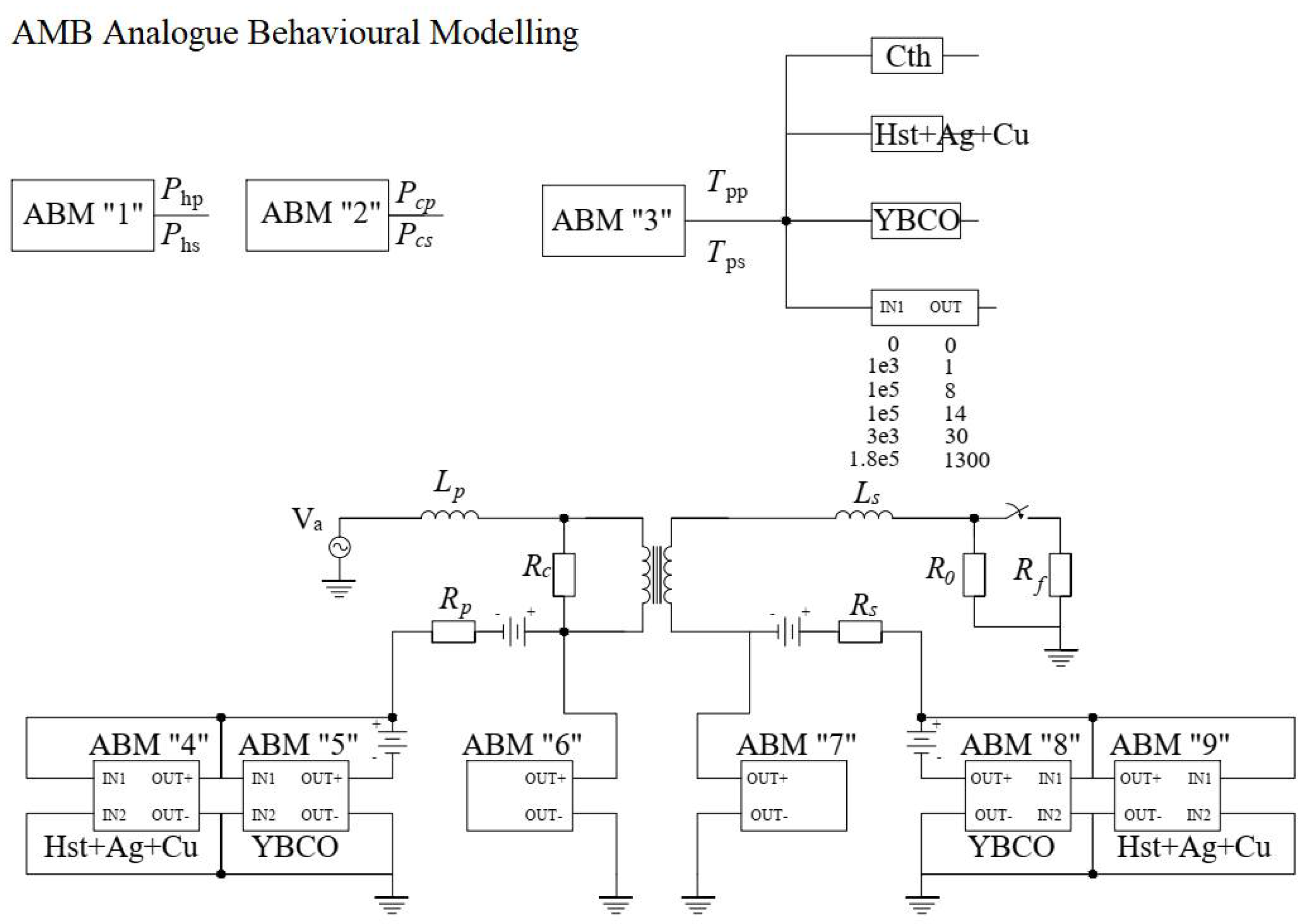
2. PSpice Model of HTS Transformer

The computer model of the single-phase HTS 21 MVA 70/10.5 kV transformer was developed on the basis of a verified computer model of the HTS 10 kVA 230/115 V transformer with its physical counterpart in the Laboratory of Superconducting Technologies in Lublin, Electrotechnical Institute in Warsaw [6]. The waveforms obtained from the measurement of the no-load condition, the load condition, and the short-circuit condition as well as the transient waveforms described in [13,17] were subjected to verification. A comparison of the results obtained from the computer model with experimental waveforms for HTS transformer of the power 10 kVA with the SCS4050 tape windings is shown in Figure 1 for the inrush current and in Figure 2 for the short-circuit current. Based on the good agreement of the obtained results, the elaborated model was extended to a more compound winding structure of the HTS transformer with a substantial power of 21 MVA and voltages of 70/10.5 kV.
To develop a computer model of a single-phase transformer HTS 21 MVA 70/10.5 kV, a computational design was used, taking into account the geometric, electrical, and thermal parameters of the transformer and its windings.
The proposed computer model of a superconducting transformer assumes that the HTS tape heats up evenly throughout the winding, the entire system is cooled equally, the heterogeneity of the HTS tape along its length is ignored, resulting from disturbances in the production process, and the influence of the heterogeneity of the magnetic field in the winding on the tape’s properties is neglected. However, the magnetic field in a large scale transformer is highly inhomogeneous and may have a strong influence on the winding critical current, especially at the end windings of high voltage (HV) and low voltage (LV) [21]. This an important factor bringing lots of complexity into the circuit model programme and should be incorporated in a more precise future model.
The 21 MVA HTS transformer windings have a much more complex structure than its low power counterpart. The primary winding consists of two and the secondary one of 10 parallel HTS tapes. The 21 MVA windings are split equally into two core columns. The primary winding has eight layers and the secondary one has seven. The cooling conditions of inner winding layers need careful consideration. Therefore, an extended thermal model of the multilayer winding was prepared. In addition to heat exchange with LN2 on the external surfaces and heat accumulation in the winding structure, it considers heat conduction in the HTS tapes and insulating foil in the radial direction.
The computer circuit model was developed in the PSpice environment. In the modelled circuit, a core made of PN ET114-27 sheet metal, kept at the temperature of the external medium, was adopted for the construction of the magnetic circuit. The core was thermally insulated from the windings, which were cooled in a LN2 nitrogen bath at 77 K. The Jiles–Atherton second level model was used to describe the nonlinear ferromagnetic core. The model contains the geometrical parameters: AREA—core cross-section [cm2], GAP—core air gap length [cm], PACK—core packing factor, and PATH—average length of the magnetic field lines inside the core. The second group of parameters for the mathematical description of the magnetic core includes: A—primary magnetisation curve shape parameter [A/m], C—elastic deformation constant of domain walls, K—deformation constant of inelastic domain walls [A/m], and MS—saturation magnetisation [A/m].
Mathematical modelling of a magnetic hysteresis loop is a complex problem and there are many approaches to it in the literature [31,32,33,34]. A starting point to this is the model originally proposed in 1986 by D. C. Jiles and D. L. Atherton (the J–A model). The fundamental J–A model of a ferromagnetic core is described by Equation (1) [31,32]
d M d H = 1 1 + c · ( M a M ) K · δ μ 0 α · ( M a M ) + c 1 + c · d M a d H
where μ0 is the magnetic permeability of vacuum; α is the magnetic field factor; M a = M s · H | H | + A is the hysteresis-free curve; Ms is the saturation magnetisation; H is the magnetic field intensity; A is the primary magnetisation curve shape parameter; K is the deformation constant of inelastic domain walls; c is the constant of elastic deformation of domain walls; and δ = −1 when dH/dt < 0 or δ = +1 when dH/dt > 0.
In recent years, the PSpice code is commonly used in the computer analysis of nonlinear magnetic circuits. It incorporates a modified level two J–A model of magnetic material, based on the fundamental J–A Equation (1), described by Equation (2) [33,34]:
d M d H = M a M ( 1 + c ) · δ · K + c 1 + c · d M a d H
The parameters of the computer model of the magnetic material described by the equations are presented in Table 1 containing the following catalogue data: the coordinates of the inflection point of the magnetisation curve Bx, Hx, the initial permeability of the magnetic material μ, the magnetic field strength of the coercivity Hc, the remanence induction Br, the saturation induction Bs, the magnetic field strength Hs, and the saturation magnetisation of Ms [30,31,32,33,34].
For the construction of the modelled windings, two types of second-generation layered tapes (HTS 2G) made of the YBCO high-temperature superconductor were used to investigate the effect of their parameters on the limitation of currents in transient states such as switching on an unloaded transformer to the network and an emergency short-circuit during transformer operation. The first type of tape was a tape with a copper stabiliser SCS12050 (Figure 3a and Figure 4), and the second type was a tape without a copper stabiliser SF 12050 (Figure 3b and Figure 4). The parameters of these tapes are summarised in Table 2 [1,2,6].
An important component of the computer model of a superconducting transformer is the mathematical description of the second generation non-linear superconducting tape (HTS 2G). Rhyner’s power law was used to model the transition of windings made of superconducting tape from the superconducting state to the resistive state [35]
E E c = ( J J c ) n
where E is the electric field intensity; J is the current density; Ec is the critical electric field intensity; Jc is the critical current density; and n is the temperature-dependent power exponent (for YBCO n0 =15 ÷ 30, T0 = 77 K).
After the transformations, the resistances of the superconductor layer can be represented by Equation (3) [35]
R Y B C O = E c l I c 0 ( I I c 0 T c T 0 T c T ) n T 0 T 1
where l is the tape length; Ic0 is the tape critical current at reference temperature T0; I is the working current value; Tc = 93 K—YBCO critical superconductor temperature; and T is the operating temperature of the HTS tape.
In order to formulate a computer model of one-phase transformer HTS 21 MVA 70/10.5 kV, a calculative project was elaborated for the geometric and electric parameters, based on the methodology depicted in [21,22,23,24,25,26,27,28,29]. These parameters are shown in Figure 5 and Table 3 [14,18].
ABM (analogue behavioural modelling) blocks were used to implement the PSpice circuit computer model of the one-phase transformer (Figure 6). ABM blocks 1, 2, and 3 represent the thermal parameters of the windings. In block ABM 1 and block ABM 2, the heating power and cooling power of the HTS tapes are defined, respectively. In the ABM 3 block, the relative temperature was calculated by considering the heating and cooling of the windings. The hierarchical block Cth calculates the heat capacity of the SCS and SF superconducting tape. The YBCO hierarchical block considers the transition of the superconductor layer to the resistive state described by Rhyner’s power law. The Hst + Ag + Cu block models the conductance of the remaining layers of the HTS tape. Table LN shows the heat flux density as a function of the temperature difference ΔT between the surface of the cooled object and liquid nitrogen.
Blocks from ABM 4 to ABM 9 are directly related to the equivalent diagram of the HTS transformer and their output currents model the currents of individual layers of the HTS tape. Blocks 4 and 9 model the Hst + Ag + Cu layer currents in a single primary and secondary winding, respectively. Blocks 5 and 8 model the YBCO current in a single primary and secondary winding, respectively. Blocks 6 and 7 carry out the multiplication of the Hst + Ag + Cu and YBCO layer currents for single primary and secondary windings, respectively, to the remaining Nup-1 of parallel primary windings or Nus-1 of parallel secondary windings, respectively.
The semi-ideal transformer consists of two fully magnetic coupled superconducting windings. Both of them are represented by the nonlinear resistance and inductance in the transient state. In the PSpice environment, the coils with magnetic core are modelled by means of the modified Jiles–Atherton model expressed by Equation (2), which describes the properties of the ferromagnetic core ET114-27. This model enabled us to reproduce the magnetic hysteresis loop for the core parameters given.
The transformer equivalent circuit also consists of parasitic elements omitted from the first subsystem. The longitudinal elements of the equivalent circuit were: the leakage inductance on the primary side of the transformer Lp and on the secondary side Ls, the primary winding resistance Rp, and the secondary winding Rs. The cross member is the resistance Rc representing the eddy current losses in the core. The auxiliary elements are the load resistance Ro and the short-circuit resistance Rf.

3. Influence of HTS Tapes on Transient Currents in 21 MVA Transformer Windings

The model of superconducting transformer described in Section 2 of PSpice was used to investigate the influence of HTS tape parameters on the limitation of transient currents in a superconducting transformer. This model made it possible to study the transient current during the process of connecting an unloaded transformer to the network and during the emergency short-circuit process while working with the load. The analysis of both transient processes was performed for two types of HTS tapes: SCS12050 with a copper stabiliser layer and SF12050 without a stabiliser.

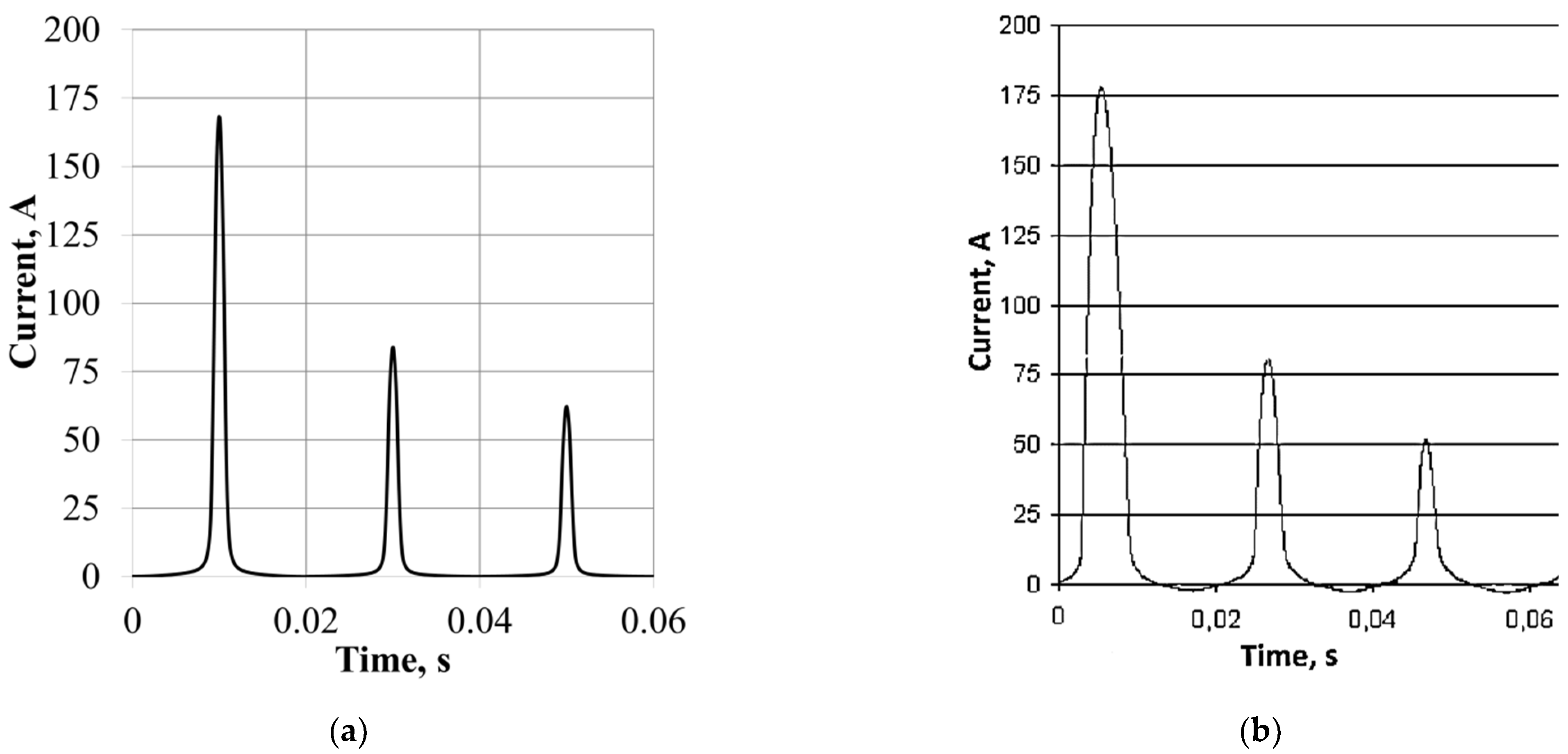
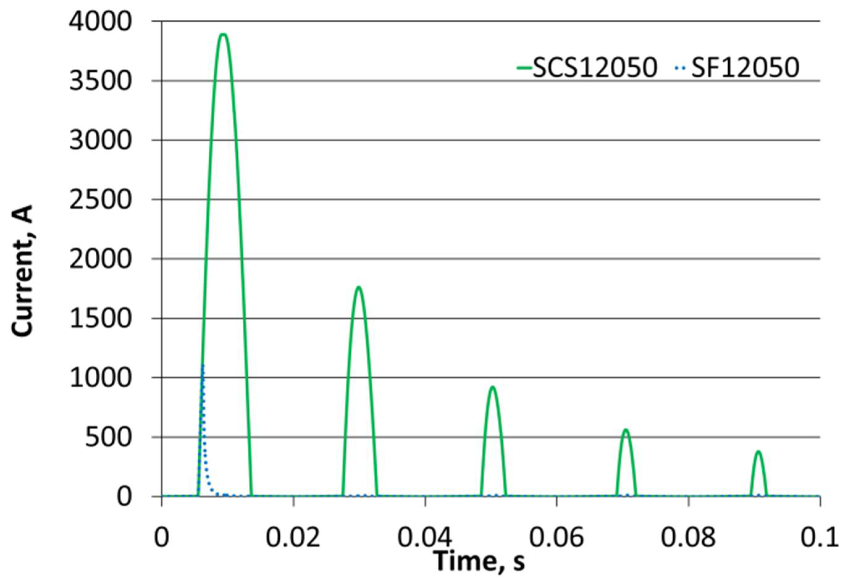
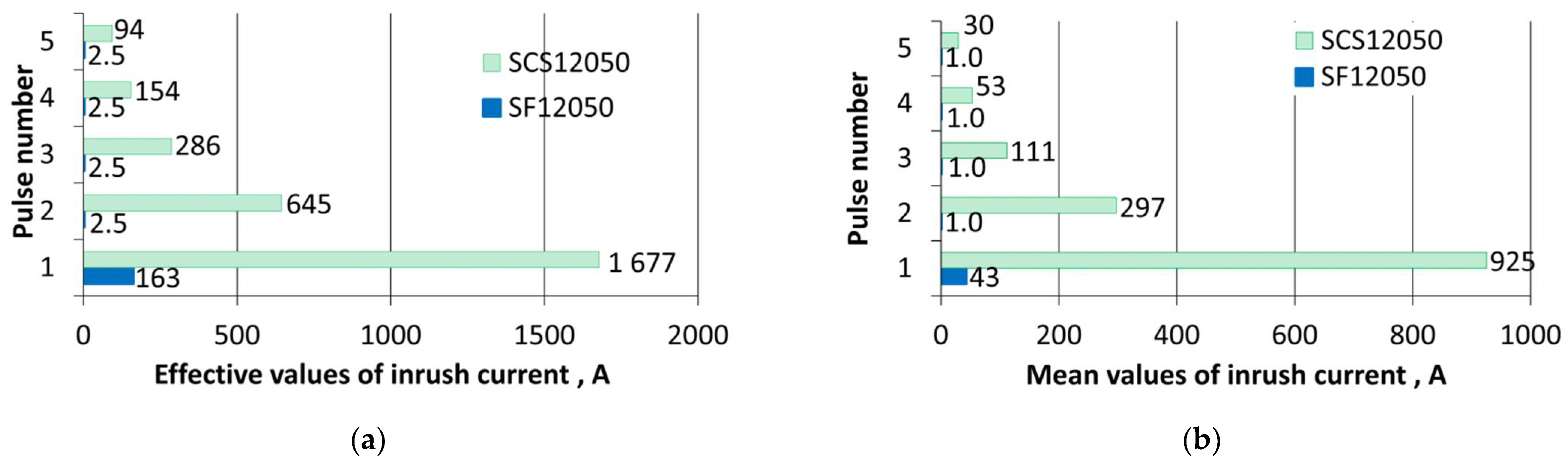
3.1. Inrush Current Modelling

When an unloaded transformer is connected to the network, a current flows in its windings about several dozen times greater than the rated current of the transformer. The large amplitude of the transformer switching current pulses as well as the long decay time of its wave cause disturbances in the power grid and deterioration of the quality of electricity. Switching on the transformer without load, due to the sudden appearance of high current, may result in damage to the insulation of the windings and the tap changer as well as the entire device. Inrush current pulses often activate electrical power protection devices and cause voltage dips.
Modelling of the switching current waveform of the superconducting transformer for both types of HTS tapes was performed for the most unfavourable initial conditions when the supply voltage passes through the zero value.
The first five unidirectional switching current pulses (Figure 7) in the HTS 21 MVA 70/10.5 kV superconducting transformer model with HTS 2G SF12050 and SCS1205 tape windings were analysed by computer. For the SCS12050 tape windings, the first switch-on current pulse was i1 SCS12050 = 3950 A, while for the SF12050 tape windings, the first switch-on current pulse was i1 SF12050 = 1250A. For a tape with a copper stabiliser, successive switching current pulses were respectively i2 SCS12050 = 1765 A, i3 SCS12050 = 980 A, i4 SCS12050 = 570 A, and i5 SCS12050 = 385 A. In the case of a tape without a copper stabiliser, the successive unidirectional current pulses were much smaller and amounted to i2 SF12050 = 9.8 A, i3 SF12050 = 9.8 A, i4 SF12050 = 9.5 A, and i5 SF12050 = 9.2 A, respectively. The critical current for the primary winding was Ic = 560 A, which was exceeded in the first four switching current pulses for the SCS1250 tape; only the fifth pulse was below this value. In the case of the SF12050 tape, only the first switch-on current pulse exceeded the critical current of the HTS primary winding. The switching current of the HTS 21 MVA 70/10.5 kV superconducting transformer with windings made of HTS 2G SF12050 tape was much lower than for its counterpart with SCS1205 windings. Additionally, the decay rate of unidirectional current pulses was higher for tape windings without a copper stabiliser.
Figure 8 shows the course of the fifth unidirectional current pulse in a HTS 21 MVA 70/10.5 kV transformer with the SF12050 tape and the SCS12050 tape. In both cases, this pulse was below the critical current of the HTS primary winding and is respectively i5 SCS12050 = 385 A, and i5 SF12050 = 9.2 A. In the case of windings made of a tape with a copper stabiliser, it was 42 times higher than that for the SF12050 tape. The highest unidirectional current ratio for the SCS12050 and SF12050 tape windings was during the second pulse
i 2 SCS 12050 i 2 SF 12050 180
where i2 SCS12050 is the second switch-on current tape SCS12050 and i2 SF12050 is the second switch-on current tape SF12050.
When performing analysis of five pulses of the unidirectional current, the superconducting transformer with the SCS12050 tape exhibited a longer disappearing time of the inrush current in comparison to the transformer with the SF12050 tape. During the switching of the HTS transformer with the latter tape, a steplike increase in the resistance took place, and the winding moved to the resistive state.
During the computer analysis, the rms values (Figure 9a) and mean values (Figure 9b) of the unidirectional current for the first five pulses were compared. For the HTS transformer with SCS12050 tape windings, the determined effective value of unidirectional current for the first five pulses was 1677 A, 645 A, 286 A, 154 A, and 94 A, respectively. In the case of tape windings without a copper stabiliser, these values were much lower and amounted to 163 A for the first pulse and 2.5 A for the next four pulses, respectively. The average values for the tape windings with a copper stabiliser for the first five pulses were 925 A, 297 A, 111 A, 53 A, and 30 A. For the windings wound with SF12050 tape, the average value was 43 A for the first pulse and 1 A for the next four pulses.
During modelling, the temperature rise was determined for the first five unidirectional current pulses of an unloaded HTS 21 MVA 70/10.5 kV transformer (Figure 10a). The dashed line shows the value of the critical temperature Tc = 93 K in the figure. During the first switching current pulse in the windings made of SCS12050 tape, the temperature of the primary winding exceeded the critical temperature value and reached the value of 110 K. During the successive pulses, the temperature increase was 9 K and 1.5 K, respectively, followed by cooling. In the case of windings made of SF12050 tape, the temperature increase during the first switching current pulse was 16 K and the critical temperature value Tc = 93 K was reached without exceeding this value, and then the windings were cooled.
The duration of the first five unidirectional current pulses of the unloaded HTS 21 MVA 70/10.5 kV transformer was also analysed (Figure 10b), giving the γ angle measure. This angle corresponds to the duration of the unidirectional current pulse. For SCS12050 tape windings, this angle was γ 1 SCS12050 = 140°, γ 2 SCS12050 = 98°, γ 3 SCS12050 = 73°, γ 4 SCS12050 = 60°, γ 5 SCS12050 = 52°, while in the case of the SF12050 tape windings, this angle had values respectively of γ 1 SF12050 = 96°, γ 2 SF12050 = 26°, γ 3,4,5 SF12050 = 27°.

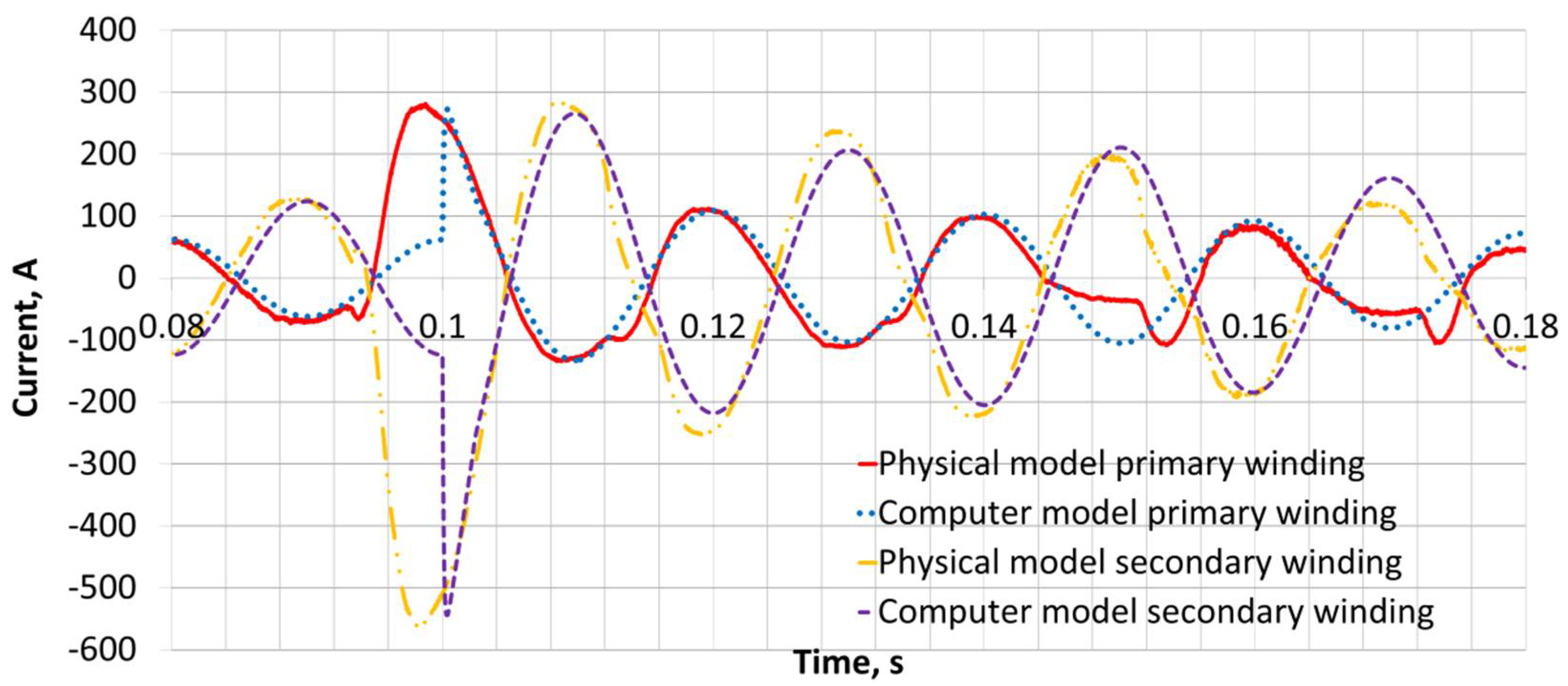
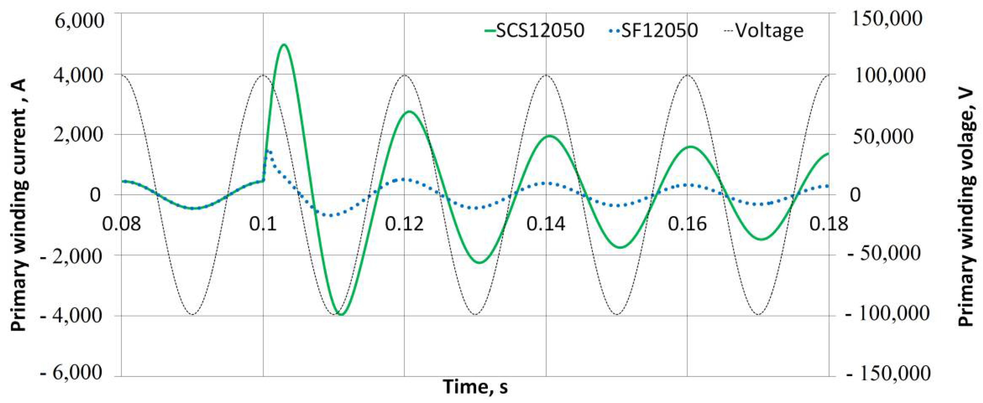
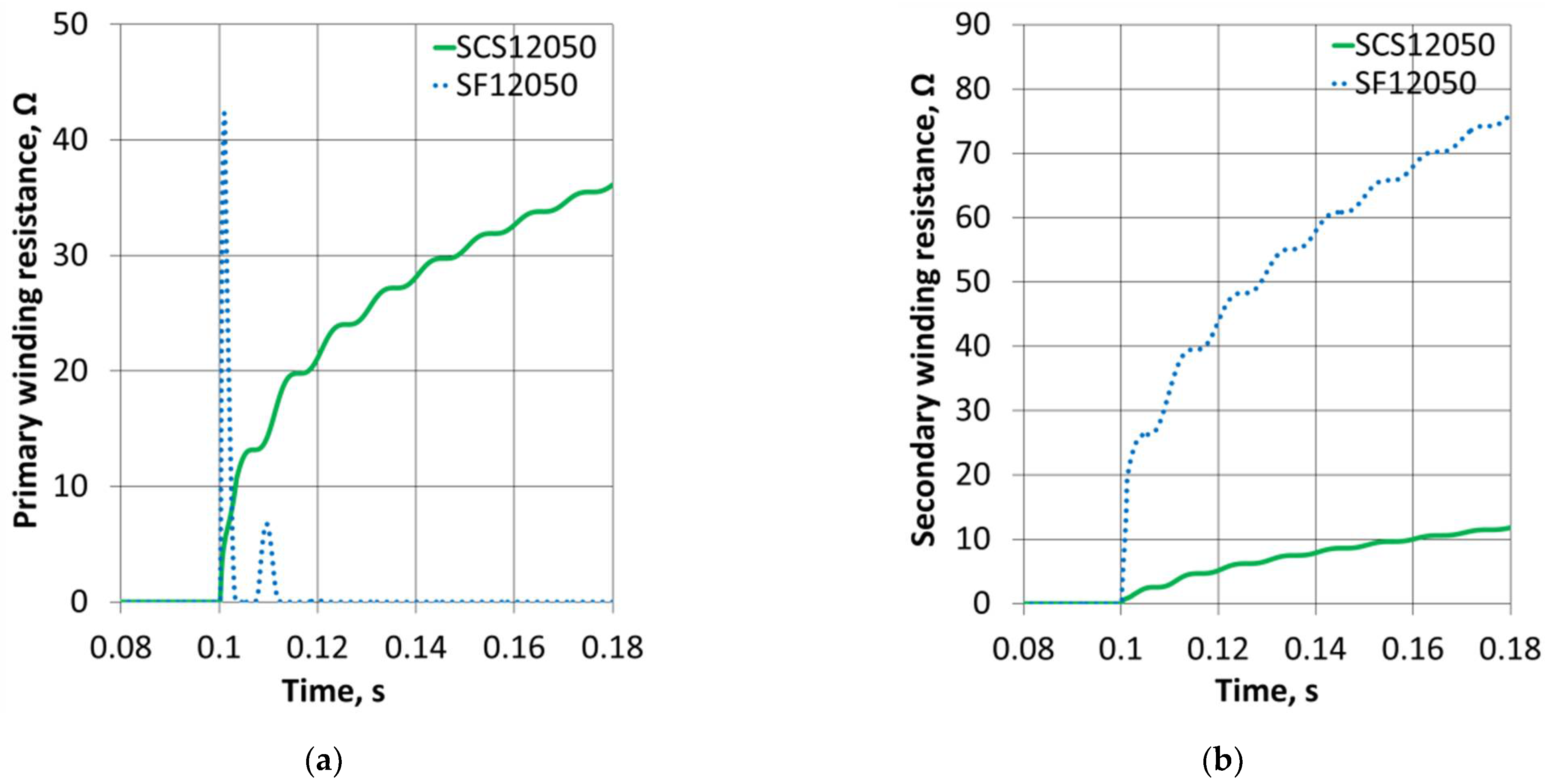
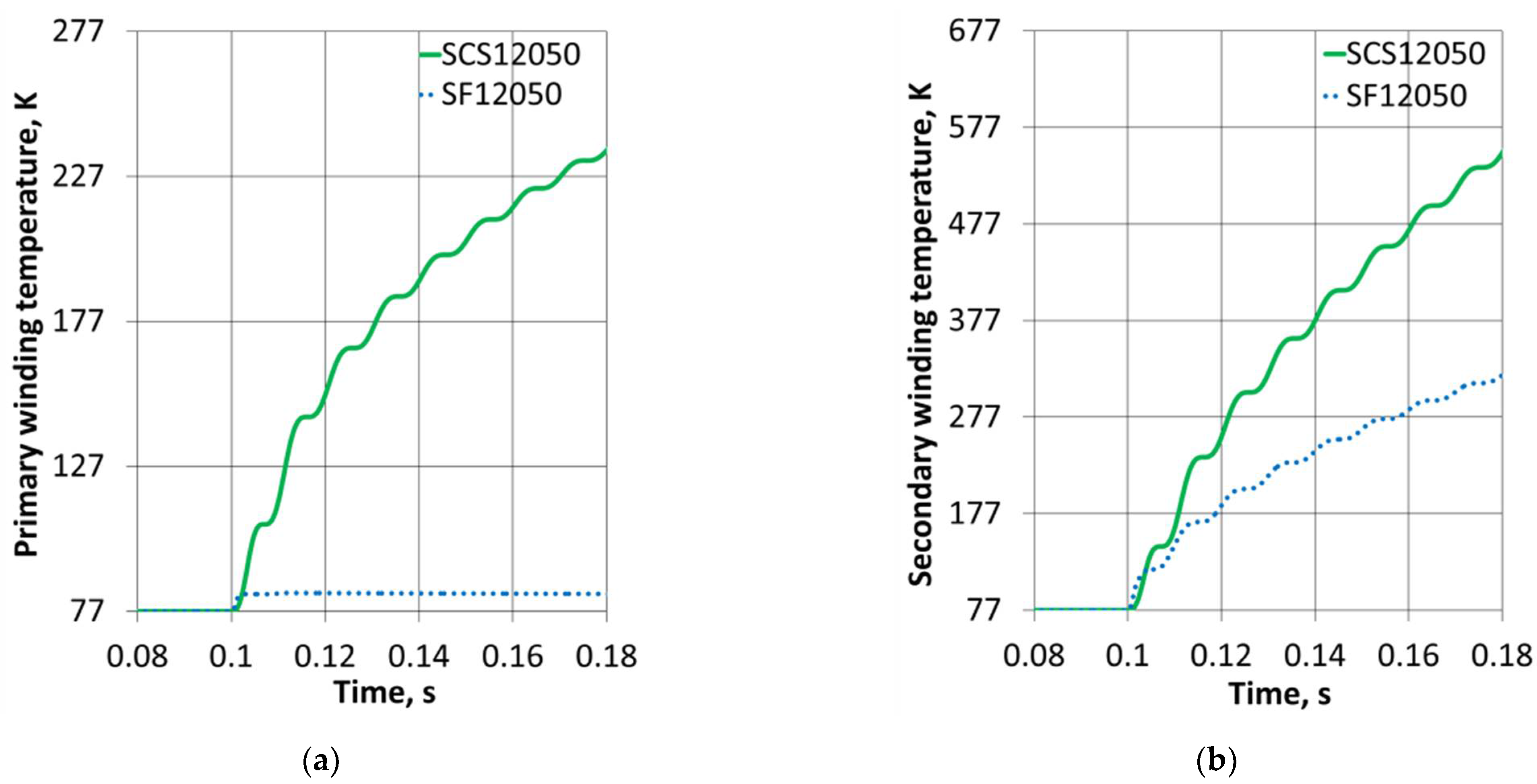
3.2. Fault Current Modelling

The second analysed transient state is an emergency short-circuit during transformer load. The short-circuit current waveform in the HTS 21 MVA 70/10.5 kV transformer in the primary (Figure 11) and secondary (Figure 12) winding made of SCS12050 and SF12050 tapes was analysed. During a short-circuit in the primary winding made of a tape with a copper stabiliser, the surge current reached the value of 4965 A, and then the short-circuit current was limited to 4000 A. After 0.08 s, the surge current value in the windings made of the SCS12050 tape was 1480 A and was still higher from the value of the critical current of the primary winding Ic = 560 A. In the case of the primary winding made of a tape without a copper stabiliser, the impulse current reached the value of 1515 A, which was 3.3 times lower than that for its equivalent made of SCS tape. There was a transition of the superconducting winding to the resistive state. The short-circuit current was limited and reached the value of 520 A. This value was below the critical current of the primary winding. Figure 11 also shows the voltage curve during a short-circuit in the primary winding. The voltage in the primary winding was at the same level during the tested time.
During a short-circuit in the secondary winding made of a tape with a copper stabiliser, the surge current reached the value of 32,998 A, and then the short-circuit current was limited to 2655 A. After 0.08 s, the surge current value in the windings made of the SCS12050 tape was 4885 A and was still higher from the value of the critical current of the primary winding Ic = 2800 A. In the case of the secondary winding made of tape without a copper stabiliser, the impulse current reached the value of 2800 A. The superconducting secondary winding was transformed to a resistive state. The short-circuit current was limited to 2753 A. This value was below the critical current of the primary winding. Figure 12 also shows the voltage curve during a short-circuit in the primary winding. A voltage dip occurred during the short circuit.
The next stage of the research was the influence of electrical and thermal parameters used to build the SCS12050 and SF12050 tape windings on the short-circuit waveforms obtained.
The influence of the increase in the resistance of the primary and secondary windings of the HTS 21 MVA 70/10.5 kV transformer made of SCS12050 and SF12050 tapes (Figure 13a,b) on the obtained short-circuit waveforms at the transformer output was analysed. Before the occurrence of the short circuit, the resistance of the primary winding made of both SCS12050 and SF12050 tapes was 0 Ω, and the windings were in a superconducting state. At the moment of short-circuit, the resistance in the primary winding made of SCS12050 tape increased to 9.8 Ω, after 0.08 s, the resistance value was 38 Ω, and the winding was kept in a resistive state. In the case of the primary winding made of tape without a copper stabiliser, at the moment of the short circuit, the resistance increased abruptly to 43 Ω, and then the winding returned to the superconducting state.
Before the short-circuit, the resistance of the secondary winding made of both SCS12050 and SF12050 tapes was 0 Ω, and the secondary winding was in a superconducting state. After a short circuit, the resistance in the secondary winding made of a tape with a copper stabiliser increased after 0.08 s to the value of 12.2 Ω. In the case of the secondary winding made of the SF12050 tape, after a short-circuit fault, the resistance increased to 76 Ω within 0.08 s.
Then, the temperature course of the primary and secondary windings of the HTS transformer made of SCS12050 and SF12050 tapes was analysed (Figure 14a,b) after the occurrence of a short circuit at the output of the secondary winding. Before the short-circuit, the temperature of the primary winding made of both SCS12050 and SF12050 tapes was 77 K, and the windings were in a superconducting state. At the moment of the short-circuit, the temperature in the primary winding made of the SCS12050 tape after 0.08 s increased by 155 K to the value of 232 K, so the winding was in a resistive state because the value of the critical temperature Tc was exceeded. In the case of the primary winding made of tape without a copper stabiliser, at the moment of the short-circuit, the temperature increased by 6.3 K to the value of 83.3 K, not exceeding the critical temperature Tc = 93 K.
Before the short-circuit, the temperature of the secondary winding made of both SCS12050 and SF12050 tape was 77 K, and the secondary winding was in a superconducting state. After the short circuit occurred, the temperature in the secondary winding made of the tape with a copper stabiliser increased after 0.08 to 479 K to the value of 556 K. In the case of the secondary winding made of the SF12050 tape, after the occurrence of the short-circuit, the temperature increased by 233 K during 0.08 s to the value of 310. K. In both cases, the temperature of the secondary winding exceeded the critical temperature value Tc = 93 K. Rapid temperature increase may deteriorate the tape parameters, and the windings will not regain their original electrical and thermal parameters.
A primary winding made of the SF12050 tape transitioned to the resistive state only partially (not in the whole volume). It may be ascertained on the basis of the winding resistance oscillations during a short-circuit (Figure 13a) that the windings lose and regain superconductivity as well as a practically unnoticeable temperature increase in the windings (Figure 14a). This was caused by the fact that the first peak of the short-circuit current (stroke current) in the primary winding only insignificantly exceeded the critical current of the SF12050 tape. The second pulse was below the critical current (Ic = 560 A, Figure 11).

4. Conclusions

A properly designed and modelled superconducting transformer with appropriate electrical and thermal parameters can limit currents in transient states. This occurs as a result of an increase in the resistance of windings made of a suitable superconducting tape and an increase in the impedance of the transformer after the superconducting windings pass from the superconducting state to the resistive state. It occurs after the pulse exceeds the inrush current and the short-circuit current, the critical current of the superconducting windings.
Due to the fact that the current limitation in the transient states of the HTS transformer occurs mainly due to the increase in winding resistance, it is possible to design a transformer with a low level of short-circuit reactance. Smaller short-circuit reactance is achieved by reducing the air gap between the primary and secondary windings. This is possible due to the fact that liquid nitrogen has good insulating properties. Thanks to a transformer designed in this way, the magnetic flux of leakage is also reduced, which results in a much better quality of electricity supplied to the end user.
The results of the transient current calculations obtained with the use of the computer model of the HTS 21 MVA 70/10.5 kV transformer with SF12050 tape windings were very favourable. Impulses of unidirectional currents of a HTS transformer with tape windings without a copper stabiliser were many times smaller than for windings made of SCS12050 tape. For windings made of the SF12050 tape, the decay time of the switch-on current was shorter than for the SCS12050 tape. Smaller values of switching current pulses and shorter decay time also resulted in smaller temperature increases of the primary winding. The short-circuit impulse current in the secondary and primary winding made of the SF12050 tape was significantly lower than that of the SCS12050 tape.
The proposed transformer model was idealised, and in fact, making windings from the SF12050 tape is not justified because the transition of the tape from the superconducting state to the resistive state causes degradation of the tape and deterioration of its electrical and thermal parameters. In the event of a short circuit at the transformer output, only the secondary winding made of tape without the SF12050 copper stabiliser goes to the resistive state, while the primary winding SF12050 goes to the resistive state only partially (not in its entire volume). The lack of full transition of the primary winding to the resistive state excludes the possibility of making the HTS transformer windings with the use of a tape without a copper stabiliser.
The analysis of the computer model of the HTS 21 MVA 70/10.5 kV transformer leads to the conclusion that only the tape with a copper stabiliser—SCS12050—is suitable for the construction of the HTS transformer windings.
However, a superconducting transformer must be protected against thermal damage and failures that occur during transient states. To protect superconducting transformers, circuit breakers capable of detecting and breaking a short-circuit in less than 100 ms should be used.
In future works, the authors plan to further extend the circuit model with magnetic field distribution, which is highly inhomogeneous in the windings and may have a strong influence on the critical current distribution. The investigation of current transients in each layer of both types of HTS tapes for switching on and short-circuit processes and temperature distribution in the windings using COMSOL Multiphysics computations may also be performed.

Author Contributions

Conceptualization, P.S. and Ł.W.; methodology, P.S.; software, Ł.W.; validation, P.S. and Ł.W.; formal analysis, P.S.; investigation, Ł.W.; resources, Ł.W.; data curation, Ł.W.; writing—original draft preparation, Ł.W.; writing—review and editing, P.S.; visualization, Ł.W.; supervision, P.S.; project administration, P.S.; funding acquisition, P.S. All authors have read and agreed to the published version of the manuscript.

Funding

This research received no external funding.

Institutional Review Board Statement

Not applicable.

Informed Consent Statement

Not applicable.

Data Availability Statement

Not applicable.

Conflicts of Interest

The authors declare no conflict of interest.

References

  1. Kalsi, S.S. Applications of High Temperature Superconductors to Electric Power Equipment; IEEE Press, Wiley: Piscataway, NJ, USA, 2011. [Google Scholar]
  2. Czerwiński, D.; Jaroszyński, L.; Majka, M.; Kozak, J.; Charmas, B. Comparison of overcurrent responses of 2G HTS tapes. IEEE Trans. Appl. Supercon. 2016, 26, 5602904. [Google Scholar] [CrossRef]
  3. Berger, A.; Chevatskiy, S.; Noe, M.; Leibfried, T. Comparison of the efficiency of superconducting and conventional transformers. J. Phys. Conf. Ser. 2010, 234, 032004. [Google Scholar] [CrossRef]
  4. Wojtasiewicz, G.; Janowski, T.; Kozak, S.; Kozak, J.; Majka, M.; Kondratowicz-Kucewicz, B. Tests and performance analysis of 2G HTS transformer. IEEE Trans. Appl. Supercond. 2013, 23, 5500505. [Google Scholar] [CrossRef]
  5. Surdacki, P.; Jaroszyński, L.; Woźniak, Ł. Modeling of the power losses and the efficiency of a 21 MVA Superconducting Transformer. 2018 EPMCCS Conf. Proc. J. Phys. Conf. Ser. 2018, 234, 032004. [Google Scholar] [CrossRef]
  6. Janowski, T.; Wojtasiewicz, G.; Jaroszyński, L. Transformatory Nadprzewodnikowe; Instytut Elektrotechniki: Warszawa, Poland, 2016; ISBN 978-83-61956-54-9. [Google Scholar]
  7. Trollier, T.; Ravex, A.; Poncet, J.M. Cryostat design for an HTS transformer. In AIP Conference Proceedings; American Institute of Physics: College Park, MD, USA, 2004; Volume 710, p. 831. [Google Scholar] [CrossRef]
  8. Sun, R.M.; Jin, J.X.; Chen, X.Y.; Tang, C.L.; Zhu, Y.P. Critical Current and Cooling Favored Structure Design and Electromagnetic Analysis of 1 MVA HTS Power Transformer. IEEE Trans. Appl. Supercond. 2014, 24, 1–5. [Google Scholar] [CrossRef]
  9. Moradnouri, A.; Vakilian, M.; Hekmati, A.; Fardmanesh, M. The impact of multilayered flux diverters on critical current in HTS transformer windings. In Proceedings of the 2019 27th Iranian Conference on Electrical Engineering (ICEE), Yazd, Iran, 30 April–2 May 2019. [Google Scholar] [CrossRef]
  10. Yazdani-Asrami, M.; Staines, M.; Sidorov, G.; Eicher, A. Heat transfer and recovery performance enhancement of metal and superconducting tapes under high current pulses for improving fault current limiting behavior of HTS transformers. Supercond. Sci. Technol. 2020, 33, 095014. [Google Scholar] [CrossRef]
  11. Yazdani-Asrami, M.; Staines, M.; Sidorov, G.; Davies, M.; Bailey, J.; Allpress, N.; Glasson, N.; Gholamian, S.A. Fault current limiting HTS transformer with extended fault withstand time. Supercond. Sci. Technol. 2019, 32, 035006. [Google Scholar] [CrossRef]
  12. Hellmann, S.; Abplanalp, M.; Hofstetter, L.; Noe, M. Manufacturing of a 1-MVA-Class Superconducting Fault Current Limiting Transformer with Recovery-Under-Load Capabilities. IEEE Trans. Appl. Supercond. 2017, 27, 1–5. [Google Scholar] [CrossRef]
  13. Surdacki, P.; Jaroszyński, L.; Woźniak, Ł. Limiting short-circuit current with a 10 kVA superconducting transformer. In Proceedings of the 2017 International Conference on Electromagnetic Devices and Processes in Environment Protection with Seminar Applications of Superconductors (ELMECO & AoS), Naleczow, Poland, 3–6 December 2017. [Google Scholar] [CrossRef]
  14. Surdacki, P.; Jaroszyński, L.; Woźniak, Ł. Modelling short-circuit current of a 21 MVA HTS superconducting transformer. J. Phys. Conf. Ser. 2021, 1782, 012036. [Google Scholar] [CrossRef]
  15. Rahman, M.A.A.; Lie, T.T.; Prasad, K. The Effects of Short-Circuit and Inrush Currents on HTS Transformer Windings. IEEE Trans. Appl. Supercond. 2011, 22, 5500108. [Google Scholar] [CrossRef]
  16. Komarzyniec, G. Calculating the inrush current of superconducting transformers. Energies 2021, 14, 6714. [Google Scholar] [CrossRef]
  17. Surdacki, P.; Jaroszyński, L.; Woźniak, Ł. PSpice modeling of the inrush current in a 10 kVA superconducting transformer. In Proceedings of the 2017 Applied Electrical Engineering (PAEE), Koscielisko, Poland, 25–30 June 2017. [Google Scholar] [CrossRef]
  18. Surdacki, P.; Jaroszyński, L.; Woźniak, Ł. Modeling of the inrush current in superconducting transformers using PSpice. In Proceedings of the 2019 Applications of Electromagnetics in Modern Engineering and Medicine (PTZE), Janow Podlaski, Poland, 9–12 June 2019. [Google Scholar] [CrossRef]
  19. Turner, A.R.; Smith, S.K. Transformer inrush current. IEEE Ind. Appl. Mag. 2010, 16, 14–19. [Google Scholar] [CrossRef]
  20. Kasztenny, B. Impact of transformer inrush current on sensitive protection functions. In Proceedings of the IEEE/PES Transmission and Distribution Conference and Exhibition, Dallas, TX, USA, 21–24 May 2006. [Google Scholar] [CrossRef]
  21. Song, W.; Jiang, Z.; Staines, M.; Badcock, R. Design of a single-phase 6.5 MVA/25 kV superconducting traction transformer for the Chinese Fuxing high-speed train. Int. J. Electr. Power Energy Syst. 2020, 119, 105956. [Google Scholar] [CrossRef]
  22. Hu, D.; Li, Z.; Hong, Z.; Jin, Z. Development of a single-phase 330kVA HTS transformer using GdBCO tapes. Phys. C Supercond. Its Appl. 2017, 539, 8–12. [Google Scholar] [CrossRef]
  23. Vysotsky, V.S.; Fetisov, S.S.; Zubko, V.V.; Zanegin, S.Y.; Nosov, A.A.; Ryabov, S.M.; Bykovsky, N.V.; Svalov, G.G.; Volkov, E.P.; Fleishman, L.S.; et al. Development and test results of HTS windings for superconducting transformer with 1 MVA rated power. IEEE Trans. Appl. Supercond. 2017, 27, 1–5. [Google Scholar] [CrossRef]
  24. Iwakuma, M.; Sakaki, K.; Tomioka, A.; Miyayama, T.; Konno, M.; Hayashi, H.; Okamoto, H.; Gosho, Y.; Eguchi, T.; Yoshida, S.; et al. Development of a 3 φ-66/6.9 kV-2 MVA REBCO superconducting transformer. IEEE Trans. Appl. Supercond. 2015, 25, 1–6. [Google Scholar] [CrossRef]
  25. Funaki, K.; Iwakuma, M.; Kajikawa, K.; Hara, M.; Suchiro, J.; Ito, T.; Takata, Y.; Bohno, T.; Nose, S.I.; Konno, M.; et al. Development of a 22 kV/6.9 kV single phase model for a 3MVA HTS power transformer. IEEE Trans. Appl. Supercond. 2001, 11, 1578–1581. [Google Scholar] [CrossRef]
  26. Tixador, P.; Donnier-Valentin, G.; Maher, E. Design and construction of a 41 kVA Bi/Y transformer. IEEE Trans. Appl. Supercond. 2003, 13, 2331–2336. [Google Scholar] [CrossRef]
  27. Funaki, K.; Iwakuma, M.; Takeo, M.; Yamafuji, K.; Suchiro, J.; Hara, M.; Konno, M.; Kasagawa, Y.; Itoh, I.; Nose, S.; et al. Preliminary tests of A 500 kVA-class oxide superconducting transformer cooled by subcooled nitrogen. IEEE Trans. Appl. Supercond. 1997, 7, 824–827. [Google Scholar] [CrossRef]
  28. Volkov, E.P.; Dzhafarov, E.A.; Fleishman, L.S.; Vysotskii, V.S.; Sukonkin, V.V. The first in Russia HTSC transformer 1 MVA 10/0 4 kV. Proc. Russian Acad. Sci. Power Eng. 2016, 27, 809–916. [Google Scholar] [CrossRef]
  29. Komarzyniec, G. 14 kVA superconducting transformer with (RE)BCO windings. In Proceedings of the 2017 International Conference on Electromagnetic Devices and Processes in Environment Protection with Seminar Applications of Superconductors (ELMECO & AoS), Nałęczów, Poland, 3–6 December 2017. [Google Scholar]
  30. Lapthorn, A.; Bodger, P.; Enright, W. A 15-kV A high temperature superconducting partial-core transformer—Part 1: Transformer Modeling. IEEE Trans. Power Deliv. 2013, 28, 245–252. [Google Scholar] [CrossRef]
  31. Jiles, D.C.; Atherton, D.L. Theory of ferromagnetic hysteresis. J. Appl. Phys. 1984, 55, 2115. [Google Scholar] [CrossRef]
  32. Jiles, D.C.; Atherton, D.L. Theory of ferromagnetic hysteresis. J. Magn. Magn. Mater. 1986, 61, 48–60. [Google Scholar] [CrossRef]
  33. Du, R.; Robertson, P. Dynamic Jiles-Atherton model for determining the magnetic power loss at high frequency in permanent magnet machines. IEEE Trans. Magn. 2015, 51, 7301210. [Google Scholar]
  34. Wilson, P.R.; Ross, J.N.; Brown, A.D. Optimizing the Jiles-Atherton model of hysteresis by a genetic algorithm. IEEE Trans. Magn. 2001, 37, 989–993. [Google Scholar] [CrossRef]
  35. Rhyner, J. Magnetic properties and AC -losses of superconductors with power law current -voltage characteristics. Physica C 1993, 212, 292–300. [Google Scholar] [CrossRef]
Figure 1. Comparison of the inrush current waveforms obtained from the computer model (a) with experimental waveforms, (b) for the HTS transformer of power 10 kVA with the SCS4050 tape windings [17].
Energies 15 01688 g001
Figure 2. Comparison of the operation short-circuit waveforms obtained from the computer model with experimental waveforms for a 10 kVA HTS transformer with the SCS4050 tape windings [13].
Energies 15 01688 g002
Figure 3. Layered structure of HTS 2G tapes: (a) SCS12050 with Cu stabiliser, (b) SF12050 without Cu stabiliser.
Energies 15 01688 g003
Figure 4. In-parallel circuit models of layered 2G HTS tapes: SCS12050 and SF12050.
Energies 15 01688 g004
Figure 5. Structure and dimensions of the HTS transformer with primary high-voltage (HV) and secondary low-voltage (LV) windings [14,18].
Energies 15 01688 g005
Figure 6. PSpice circuit computer model of one-phase transformer HTS 21 MVA 70/10.5 kV.
Energies 15 01688 g006
Figure 7. The course of the first five pulses of unidirectional switching current in a HTS transformer with SF12050 tape and SCS12050 tape.
Energies 15 01688 g007
Figure 8. The course of the fifth impulse of unidirectional switching current in a HTS transformer with SF12050 tape and SCS12050 tape.
Energies 15 01688 g008
Figure 9. (a) RMS values and (b) average values for the first five switching current pulses.
Energies 15 01688 g009
Figure 10. (a) HTS 2G SF12050 and SCS12050 primary winding temperature rise. (b) The value of the γ angle for HTS 2G SF12050 and SCS12050 transformers.
Energies 15 01688 g010
Figure 11. Short-circuit current and voltage waveform in the primary winding of a HTS 21 MVA 70/10.5 kV transformer with windings made of SF12050 tape and SCS12050 tape.
Energies 15 01688 g011
Figure 12. Short-circuit current and voltage waveforms in the secondary winding of a HTS 21 MVA 70/10.5 kV transformer with windings made of SF12050 tape and SCS12050 tape.
Energies 15 01688 g012
Figure 13. (a) The course of resistance in the primary winding of the HTS 21 MVA 70/10.5 kV SF12050 and SCS12050 transformer. (b) Resistance waveform in the secondary winding of the transformer HTS 21 MVA 70/10.5 kV SF12050 and SCS12050.
Energies 15 01688 g013
Figure 14. (a) Temperature course in the primary winding of the HTS 21 MVA 70/10.5 kV SF12050 and SCS12050 transformer. (b) Temperature course in the secondary winding of the transformer HTS 21 MVA 70/10.5 kV SF12050 and SCS12050.
Energies 15 01688 g014
Table 1. Parameters of the computer model of magnetic material in the PSpice programme.
ParameterDescriptionValue Implemented in the ModelEquationCatalogue Data
AShape parameter of the normal magnetisation curve7.23 A/m A = H x c 1 + c · M x μ 1 1 1 M x M s 3 · M x M s
M x = B x μ 0 H x
Hx, Bx, Ms, C
CReversible energy loss parameter0.3 C = μ 0 H c ( μ 1 ) B r μ μ 0 H c Hc, Br, μ
KIrreversible energy loss parameter10 A/m K = H c B r B r μ 0 H c Hc, Br
MSSaturation magnetisation1.50 MA/m M s = B s μ 0 H s Hs, Bs
AREACore cross-section area3160 cm2
PACKCore packing factor0.90
PATHAverage length of magnetic flux path463 cm
GAPCore air gap0.11 mm
Table 2. Parameters of HTS 2G tapes: SCS12050 and SF12050 [1,2,6].
Type of HTS TapeSCS12050SF12050
ManufacturerSuper PowerSuper Power
Thickness [mm]0.060.1
Width [mm]1212
Tape strength [MPa]550350
Critical current density [A/mm2]220450
Critical current [A]300300
Equivalent tape resistance (room temperature) [Ω/m]0.003620.105
Resistivity of the tape substrate (77 K) [µΩcm]125125
Tape length [m]200200
Table 3. Parameters of the HTS 21 MVA 70/10.5 kV transformer [14,18].
ParameterHTS Transformer
Core material (electrical sheet)ET 114-27
Width/thickness of HTS tape [mm]
SF12050
SCS12050
 
12/0.055
12/0.1
Critical current of HTS tape [A]280
Primary voltage [kV]69.86
Secondary voltage [kV]10.5
Primary current [A]301
Secondary current [A]2000
Number of parallel tapes in HTS windings HV/LV2/10
Magnetic flux density [T]1.63
Total number of windings turns HV/LV712/102
Cable length HV/LV [m]3791/2360
Publisher’s Note: MDPI stays neutral with regard to jurisdictional claims in published maps and institutional affiliations.

