Article

Heat Exchanging Grid Structures Based on Laser-Based Powder Bed Fusion: Formation Process and Boiling Heat Transfer Performance

1
School of Mechanical and Automotive Engineering, Shanghai University of Engineering Science, Shanghai 201620, China
2
School of Mechanical and Power Engineering, East China University of Science and Technology, Shanghai 200237, China
*
Authors to whom correspondence should be addressed.
Energies 2022, 15(5), 1779; https://doi.org/10.3390/en15051779
Submission received: 14 December 2021 / Revised: 21 January 2022 / Accepted: 24 January 2022 / Published: 28 February 2022
(This article belongs to the Special Issue Enhanced Two-Phase Heat Transfer)

Abstract

:
Microchannel structures possess high efficiency and high boiling heat transfer coefficient of two-phase flow. In particular, the grid structure has the advantages of a simple pattern, large load capacity, and good surface adaptability. Employing the laser-based powder bed fusion (L-PBF) manufacturing technology, a new method of forming heat transfer grids with a controllable structure is proposed in this study. The formation principle, process, and the reasons for improvements in the boiling heat transfer performance were investigated with stainless steel materials. Laser scanning with varying scan spacings was used to prepare multiple structures with different grid widths and wall heights. On this basis, the porosity and pore morphology of the grid structures were analyzed, followed by pool boiling heat transfer experiments. The results revealed that the grid structure significantly affected the nucleate boiling behavior and increased the critical heat flux (CHF). It was found that the 0.5 mm sample exhibited optimum critical heat transfer performance, with an improvement of 10–27% compared to those of the other four samples (minimum of 63.3 W·cm−2 and maximum of 93.9 W·cm−2). In addition, for samples with a grid width greater than 0.5 mm, the boiling slightly decreased by <5%. When the grid width was further increased, the flow resistance effect and the bubble synapse generation effect tended to converge. In these cases, boiling heat transfer only occurred in a single phase along the direction of the medium wall thickness, thus failing to achieve two-phase heat transfer through bubble growth and collapse.

1. Introduction

Improving surface structures [1], which typically include grooves, fins, and porous surfaces of various shapes, is the main approach adopted for enhancing boiling heat transfer. The porous surface heat exchanger developed in the 1960s has had wide application prospects in the industry due to its high boiling efficiency, low-temperature difference boiling, high critical heat flux (CHF), and good anti-fouling capability [2]. With the increasing heat dissipation requirements of devices, liquid cooling technology is being increasingly applied. Traditional single-phase liquid cooling technology is not ideal for high heat fluxes. However, the boiling heat transfer process, which is a phase-change liquid cooling technology, has a high heat exchanging efficiency and is playing an increasingly important role in research on high-power equipment cooling [3]. The pore morphology and structural parameters (porosity, average pore size, etc.) of a porous structure are closely related to the number of nucleation sites and the vapor-escaping and liquid-rewetting channels in the boiling heat transfer process. Furthermore, the pores can be used as bubble-escaping and liquid-rewetting channels, delaying the arrival of the CHF [4]. Therefore, the porous structure for boiling heat transfer has obvious advantages over other heat-transfer-enhancing structures and generally includes the following types: original surface processing (fins, cavities, or porous structures prepared by microelectromechanical technology) [5], surface-deposited porous structures (chemical vapor deposition, liquid deposition, plasma deposition, etc.) [6], porous structures of various metal particles (sintering or coating), and a few newly developed techniques [7].
One of the key parameters that characterize boiling heat transfer performance is the CHF. The CHF can be enhanced by increasing the surface area, wettability, or capillary wicking. The microchannel structure has a high surface-to-volume ratio that can increase the solid-liquid contact area, form more nucleation sites, reduce the initial boiling temperature, and significantly enhance pool boiling heat transfer [8]. Furthermore, the pores can act as bubble-escaping and liquid-rewetting channels, as well as delay the arrival of the CHF [9]. Obviously, surface porous structures and microporous structures can delay the CHF more compared to a flat surface, and this topic has been studied by many researchers. Chang et al. [10] studied the boiling heat transfer of microporous and porous surfaces in the form of coatings by immersing them in saturated FC-72; they found that the two coatings exhibited different boiling properties in terms of initial superheat, nucleate boiling, and CHF. Targeting the issue of enhanced nucleate boiling on a microporous copper surface, Mohamed S. E. [11] studied the saturated boiling of PF-5060 dielectric liquid on a microporous copper surface using the electrochemical deposition method and demonstrated that the results of nucleate boiling were significantly better than those reported for the microporous dielectric liquid. Ultimately, the CHF was increased by 70% and the degree of superheat was greatly reduced. Suazlan et al. [12] studied the CHF of deposited nanoparticle surfaces attached to a porous honeycomb plate with different orientations in a heater and proved that the deposition of nanoparticles on the porous plate greatly increased the CHF of the heated surface. Deng et al. [13] investigated the pool boiling heat transfer performance of porous structures with re-entrant cavities (PS-RC), which were formed via the solid-state sintering of copper powders. Their results showed that PS-RC significantly reduced wall superheat. In addition, cross-scale composite porous structures were proven to be effective in enhancing boiling heat transfer. The accurate control of composite pore size and pore structure thickness is important for studying the mechanism for enhancement in the boiling heat transfer process. Targeting the heat transfer characteristics of pool boiling at atmospheric pressure, Liu et al. [14] compared the boiling heat transfer performance of a uniform porous structure (0.6 mm pore size) with a composite porous structure. Their results revealed that the composite porous structure could significantly increase the CHF compared to an ordinary copper surface. Li et al. [15] studied the effect of liquid replenishment in a multiscale modulated porous structure on the CHF and heat transfer coefficient. Comparative experiments were performed for a flat surface, a porous structure with even thickness, a modulated porous structure, and a hybrid modulated porous structure. Their results demonstrated that the maximum pool boiling heat flux of the modulated porous structure was 450 W/cm2, which was more than three times the flat surface CHF. In addition, the maximum heat transfer coefficient was three times higher than that of an ordinary copper surface. In addition to macrochannel studies, Jaikumar and Kandlikar [16] studied the effect of microchannel structures on pool boiling heat transfer performance by using porous fin tops on FC-87 fluids in open microchannels to enhance the boiling performance of the electronic cooling pools. The cohesion of the channel width and depth was studied, and it was demonstrated that the main reason for the enhancement was the separate liquid evaporation path on the top surface of the porous fin. Kim et al. [17] used microelectromechanical system technology to prepare a microporous heat transfer structure and investigated its effectiveness in enhancing the boiling heat transfer and CHF. Their experimental results revealed that the heat transfer coefficient was more than 300% compared to bare surfaces, and the CHF was 350% higher. In addition, non-uniform structured surfaces were developed based on the uniform structure [18]. The issue of boiling heat transfer in such structures has become increasingly important in the past few years. Liter and Kaviany [19] discussed the theory and experiment of enhancing pool boiling CHF using modulated porous coatings, which increased the critical boiling heat flux by nearly three times that achieved by a flat surface. The modulation separated the liquid phase from the vapor phase, thereby reducing the liquid–vapor countercurrent resistance near the surface. Similar studies on two-dimensional (2D) and three-dimensional (3D) modulated porous surfaces have also been performed, observing further increases in CHF [20]. Targeting the capillary effect of non-uniform microporous structures on pool boiling heat transfer, Ahn et al. [21] studied the effect of water absorption on CHF enhancement during pool boiling. Referring to the correlation between wettability and CHF proposed by Kandlikar, Ahn developed a pool boiling CHF correlation function to reflect the effect of capillary wicking on the surface of microstructures and nanostructures during boiling heat transfer, and they found that the surfaces of both types of structures exhibited higher absorption capacities.
The existing fabrication methods of microporous structures have mostly been developed from traditional sintering methods and have drawbacks such as uncontrollable pore structures and complex manufacturing processes. Furthermore, traditional sintering and forming porous technology has certain difficulties in the manufacturing of controllable pores. Thus, it has become necessary to study the effects of controllable structures on boiling heat transfer and describe the mechanisms underlying the different structures and parameters. A simpler way to effectively produce controllable and non-uniform microporous surfaces for practical applications is also an urgent need. Plenty of research results have demonstrated that it is of great value to use the laser-based powder bed fusion (L-PBF) technique to shape microporous structures for boiling heat transfer. The L-PBF additive manufacturing technology has high processing flexibility and can form lattice structures with high surface-to-volume ratios for boiling heat transfer. Yadroitsev et al. [22] used L-PBF technology to accurately reproduce the geometry of microporous heat transfer structures and to manufacture thin-wall 3D filters and custom filters with micron-level channels. Wong and Leong [23] studied the saturated pool boiling performance of a porous lattice structure prepared by L-PBF and found that the porous structure exhibited a significantly enhanced nucleate boiling heat transfer coefficient and a CHF delay relative to a flat surface. Zhang et al. [24] studied the pool boiling performance of a 3D grid structure made by L-PBF and experimentally showed that the grid structure, due to its zoning, had a significant impact on the nucleus boiling behavior and increased the CHF to be three times that of the smooth surface. This effect suppressed the Helmholtz instability and the hot spot expansion of limited bubbles and near-surface areas. L-PBF has been successfully applied in the field of cutting-edge materials manufacturing such as aerospace, human implants, and complex die designs, and it is used for constructing complex internal or bionic structures [25]. For porous structures [26], L-PBF can precisely control structural parameters, e.g., pore size, porosity, and geometry [27].
Microchannel radiators have high efficiency and high heat transfer coefficient in two-phase flow boiling. In particular, the grid structure has the advantages of a simple pattern, large load capacity, and good surface adaptability. Combining the L-PBF technique with the requirements of boiling heat transfer on the microchannels while taking advantage of the merits of the grid structure, a new efficient method for forming controllable boiling heat transfer grid structures with microchannels is proposed in this study. Based on the requirements of boiling heat transfer, the formation method and process were explored for the grid structure. The influence of grid width on the bubble escape and liquid replenishment during boiling heat transfer was analyzed, thereby explaining the difference in the boiling heat transfer performance among structures with different grid widths. Specifically, the L-PBF technique was used for preparing a 3D thin-walled grid structure of stainless steel materials using laser direct interval scanning. Following this, boiling heat transfer experiments were conducted for structures with different grid widths in water to test their performance in enhancing boiling heat transfer. Finally, the influence of the structural parameters on boiling heat transfer and the enhancement mechanism were discussed, providing important guidance for the design of 3D structured heat transfer channels for boiling enhancement. Furthermore, L-PBF technology constitutes a new effective approach for manufacturing innovative boiling heat transfer structures with controllable parameters, which opens up a new direction for the study of boiling heat transfer mechanisms.

2. Methods, Experimental Platform and Materials

2.1. Principle of the Formation of the Grid Structure

The principle of forming a grid structure using the L-PBF technique is shown in Figure 1. With the approach of layer-by-layer and line-by-line laser scanning, the scan spacing was increased so that the melting channels did not overlap. In addition, transverse and longitudinal scanning were alternately performed, forming a large number of neatly arranged square holes. Furthermore, no overlapping transition was present between the upper and lower layers, leaving micro-gaps between the layers as the liquid flow channels.

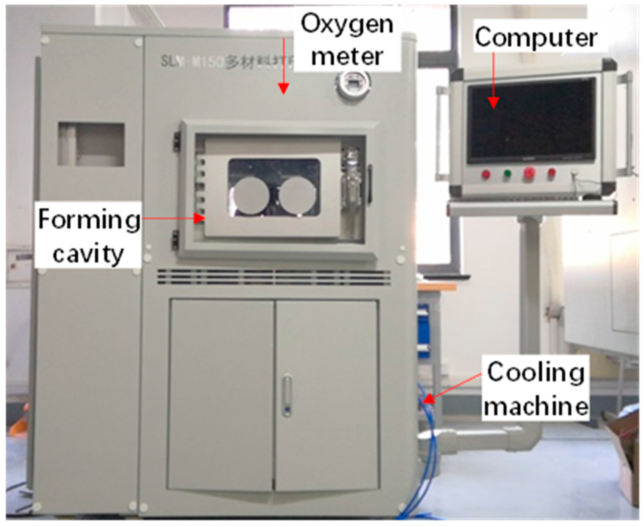
2.2. L-PBF Experimental Facility

In this study, the grid structure was formed using the L-PBF process. The laser-based powder bed fusion experimental platform is shown in Figure 2; it consisted of a work system and forming cavity, a laser system, a control system. The laser was an RF-C300L continuous fiber laser from Wuhan Raycus Fiber Laser Technologies Co., Ltd., and its parameters are displayed in Table 1. The printer had a formation size of 150 × 150 × 120 mm and fed powders via a cylinder.
During the L-PBF-forming process, the experimental platform could be evacuated or filled with a protective gas depending on the material and processing requirements to prevent the oxidation or burning of the metal powders during the melting and solidification processes. The specific steps of L-PBF forming are listed as follows:
(1)
Design the 3D structural model and convert it to STL format file.
(2)
Use special model processing software to transform the STL model into contour paths and laser scanning paths layer by layer; calculate the scanning paths according to the structural properties of G-surface structure.
(3)
Use the scraper to spread the powder on the substrate of the working platform, and then use the scan system XY mirrors to reflect the laser in order to scan and melt selected regions of the slicing layer.
(4)
After the scanning is completed, the working platform substrate decreases layer thickness, and the powder spreading and laser scanning are performed again. Repeat the above steps until the part is printed.
(5)
Remove the working platform substrate and use a cutting machine to separate the parts from the base substrate.
In L-PBF-forming process, according to the material and processing requirements, the experimental platform was filled with protective gas to prevent the metal powder from oxidizing or combusting during the melting.

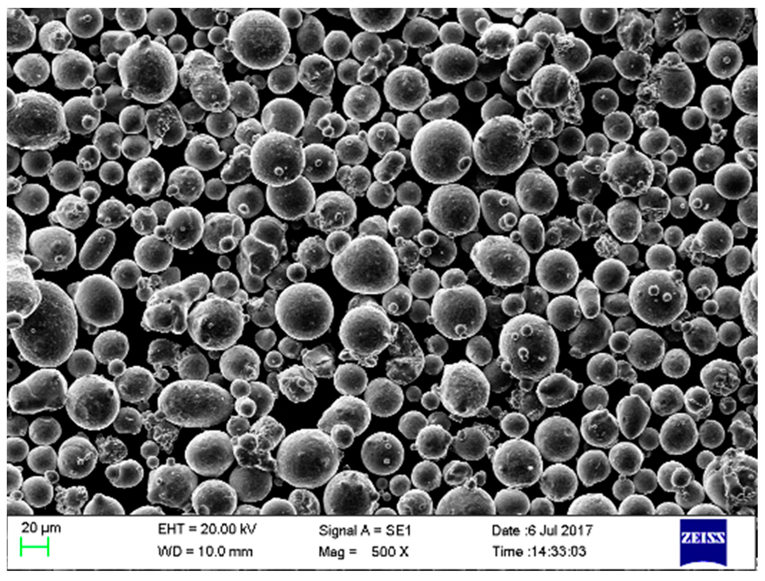
2.3. Experimental Material

In this study, 316L stainless steel was used as the experimental material. Its micromorphology, obtained by performing scanning electron microscopy (SEM), is shown in Figure 3, and its chemical composition is presented in Table 2. Its particle size distribution was as follows: sphericity of 96%, oxygen content of 398 ppm, particle size of D10 (23.1 µm), particle size of D50 (35.3 µm), and particle size of D90 (53.3 µm).

2.4. Forming Process Parameters for the Grid Structures

Based on the microchannel formation principle mentioned above, 316L stainless steel powder was used as the experimental material manufactured by L-PBF process printing to form 15 sets of grid structure samples under different process parameters. The size of all grid structures was 22 × 22 × 10.7 mm, and the line-by-line scanning approach was employed. The forming process parameters are presented in Table 3.
If the scan spacing was too small, no through-holes could be formed. On the other hand, if the scan spacing became excessive, the low laser energy density led to poor forming quality or even formation failure. Therefore, when forming the grid structures, the scan spacing was set in the range of 0.1–0.9 mm, considering that the 316L stainless steel powder had a particle diameter of approximately 15–53 µm.

3. Pore Morphology and Structure Analysis of the Grid Structure

Among the main factors that influence the enhancement of boiling heat transfer by the microgrid structure are its material, pore morphology, and structural parameters. The principal structural parameters include the hydraulic diameter, porosity, and thickness. Therefore, it is necessary to investigate the effect of microchannel spacing on boiling heat transfer. For this purpose, the aforementioned design and formation parameters were used for preparing the grid structures using the L-PBF prototype. The formed parts are shown in Figure 4.

3.1. Influence of Scan Spacing on Pore Morphology

As shown in Figure 5, the pores of the grid structures with a scan spacing of 0.2–0.5 mm were regular, though a large number of spherical particles existed in the inner walls of the pores. A comparison with Figure 3 shows that these spherical particles had a size and morphology consistent with those of the powder particles that could thus be identified as semi-melted powder particles that were bound to the inner walls. Powder bonding resulted in rough inner hole surfaces that facilitated the formation of potential nucleation sites and enhanced boiling heat transfer. On the other hand, powder bonding also had a significant impact on porosity [27]. As shown in Figure 6, the amount of powder bound on the inner walls reduced as the scan spacing increased, as a larger scan spacing corresponded to a weaker influence of the heat-affected zone on the powder inside the hole during laser scanning.
The microchannel structures of the polished grid samples (the pictures were taken with the ZEISS Axio Observer A1M microscope). At a scan spacing of 0.1 mm, a regular porous structure failed to form, mainly due to the partial overlap between the melting channels when the scan spacing was small. On the other hand, the melting channels were not fully overlapping, which eventually resulted in irregular pores. When the scan spacing was increased to 0.2 mm, some holes in the formed grid structure were blocked, mainly because the large powder particles (with a diameter of 15–53 µm) adhered to the hole (with a diameter of about 100 µm) wall, thus easily forming blockages. Therefore, to ensure that the pores of the grid structure were open, the scan spacing needed to be greater than 0.2 mm.

3.2. Influence of Laser Power on Pore Morphology

To analyze the influence of the laser power on the microchannel pores, a well-formed grid at a 0.3 mm scan spacing was selected for comparison. The polished grid structure samples formed under different laser powers are shown in Figure 6. Among them, the 180 W laser power failed to fully form regular pore shapes in the grid structure because the low power resulted in fewer melting liquid phases, making it difficult to form continuous melting channels during scanning. In addition, the liquid phases that were isolated from each other penetrated the pores and bonded with the incompletely melted powder. When the laser power increased from 180 to 220 W, the pore wall became regular and the accuracy of the pore size improved due to the additional liquid phases induced by the increased laser power that promoted the generation of continuous melting channels. The grid structure formed under 240 W of laser power had round pores, mainly due to excessive liquid phase generation under the high laser power.

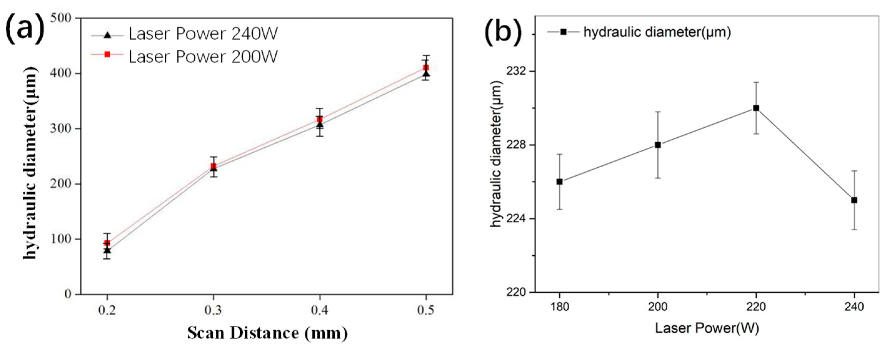
3.3. Analysis of the Hydraulic Diameters of Different Grid Structures

The size of the hydraulic diameter in the grid structure can significantly affect the flow velocity of a medium. Therefore, to further analyze the influence of the grid structure on the hydraulic diameter when the water was flowing, different grid structure samples with a scan spacing of 0.2–0.5 mm were analyzed in this study. Their hydraulic diameters and porosities were obtained with image processing. The five grid structures were formed under a laser power of 180–240 W. The hydraulic diameter and porosity results calculated from the image areas of different regions are presented in Figure 7.
As shown in Figure 7a, the hydraulic diameter increased with the increase in scan spacing when the laser power was kept fixed. The hydraulic diameter of the sample with a 0.2 mm scan spacing was relatively small, mainly due to the blockage of some holes, as shown in Figure 7b. The hydraulic diameter of the grid structure formed by 200 W of laser power was slightly larger than that achieved using 240 W of laser power. As shown in Figure 7b, when the scan spacing was fixed at 0.3 mm, the hydraulic diameter slightly varied in the range of 227.6–235.5 µm when the laser power increased from 180 to 240 W. Though the varied laser powers generated different numbers of liquid phases, the laser spot diameter remained constant. Therefore, the width of the melting channels did not change much, so the variations in the hydraulic diameter were small.

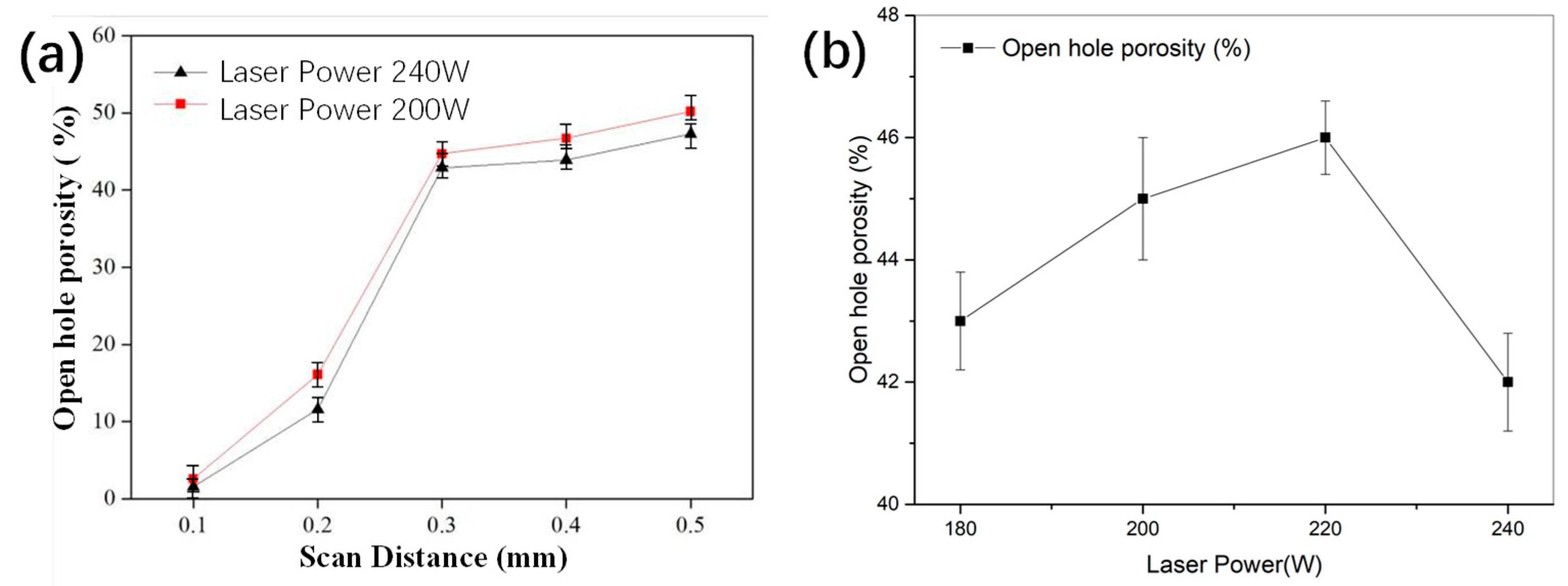
3.4. Open Porosity Analysis for Grid Structures

Porosity has a significant influence on the boiling heat transfer of grid structures. To analyze the effects of the process parameters on grid structure porosity, different scan spacings and laser powers were selected to form the grid structures. As shown in Figure 8a, for the same laser power, the open porosity increased with the increase in scan spacing. A step change in the open porosity was observed when the scan spacing was increased from 0.2 to 0.3 mm, which was mainly due to the blockage of some holes in the grid structure at a scan spacing of 0.2 mm. When the scan spacing was in the range of 0.3–0.5 mm, the formed grid structures exhibited little pore clogging and high porosities. The grid structure formed at a laser power of 200 W had a slightly higher open porosity than that formed at 240 W.
As shown in Figure 8b, when the laser power varied from 180 to 240 W at a fixed scan spacing of 0.3 mm, the open porosity slightly fluctuated in the range of 42.9–45.9%. In particular, when the laser power increased from 180 to 200 W, the open porosity slightly rose because more liquid phases were produced, which allowed for a larger number of continuous melting channels and less liquid phase penetration into the pores. When the laser power reached 240 W, excessive liquid phases were produced, resulting in round holes (as shown in Figure 6d) and a consequent small decrease in the open porosity. From the results, according to the characteristics of the macroporous structure of the grid parts, the internal porosity of the metal grid parts varied from 5% to 50% according to the scanning spacing. The macroporosity of the surface was consistent with the macroporosity of the internal grid structure.

4. Experimental Details and Analysis of the Boiling Heat Transfer Characteristics of the Grid Structures

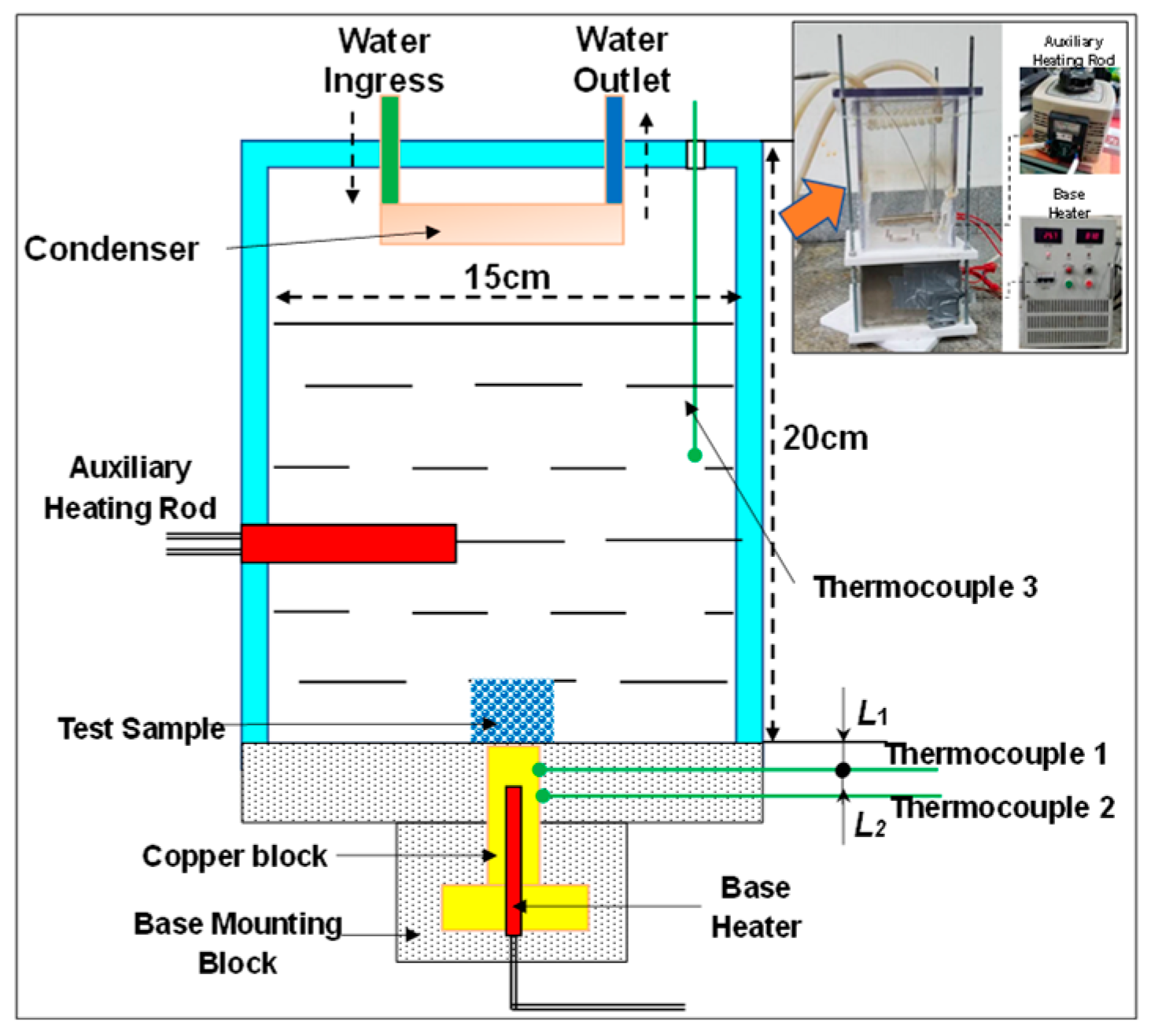
4.1. Experimental Platform and Calculation Method for Boiling Heat Exchange

The pool boiling heat exchange platform included a boiling heat transfer test host device, an auxiliary heating device, a main heating device, and a data acquisition device (Figure 9). The main heating device could achieve different heat inputs at the bottom of the sample by adjusting the power of main heating block rod [24]. The experimental host device comprised a main container, a condensing tube, thermocouples, an insulating base, and heating rods. The main container was made of transparent materials and comprised a glass container and upper and lower cover boards [28]. Two thermocouples, T1 and T2, were successively placed on the copper block to obtain the heat flux and upper wall temperature of the copper block. Thermocouple T3 was used to measure water temperature [29]. The accuracy of thermocouples 1 and 2 was 0.05 mm, and the distance of two thermocouples was 15 mm. The main heater was turned to a specific power, and the temperature data collected using the thermocouples were recorded when the system reached a quasi-steady state. The heating power of the main heating rod was gradually increased, and the data of the thermocouples attaining the stable state were monitored.
The heat flux q/W∙cm−2 was calculated as:
q = λ Cu T 2 T 1 L 2 × 10 4
The wall temperature Tw/°C of the copper block was calculated as [25]:
T W = T 1 T 2 T 1 L 2 L 1
The temperature measurement error of the K-type thermocouple was ±0.2 °C, and the length measurement error of the vernier caliper was ±0.01 mm.

4.2. Comparative Analysis of the Grid Structure Samples of Different Widths and Heights

To analyze the effect of the grid size on the boiling heat transfer process, the grid structure samples formed at different scan spacings were tested using the boiling heat transfer test platform mentioned in the previous section. The hatch distance ranged from 0.1 to 0.6 mm, and the sample height was kept fixed. The boiling heat transfer results are shown in Figure 10. Evidently, other than the sample with a 0.2 mm grid width, the influence of the grid width on the nucleus boiling performance first increased and then decreased when the grid width was greater than 0.5 mm. The exception of the 0.2 mm grid width, as shown in Figure 5, was due to the fact that the flow channel was almost blocked by the adhering particles. Under this circumstance, no nucleate boiling zone was formed on the sidewall of the microchannel, so its heat transfer performance was not comparable with the other four cases. As shown in Figure 10a, when the sample grid width increased from 0.7 to 0.9 mm, a slight boiling reduction of <5% was observed. This occurred as the microchannel was filled with fluids at a high temperature gradient. When the grid width exceeded 0.5 mm, the flow resistance during nucleus boiling decreased, the high-temperature flow rate increased, and the number of bubbles generated by wall synapses decreased, which led to a decrease in the heat flux carried away by the bubbles. When the grid width became even larger, the flow resistance and the bubble synapse generation effects converged. In this scenario, boiling heat transfer could only occur along the thickness direction of the medium wall, not by bubble growth and collapse. A comparison of the five samples revealed that the CHF of the 0.5 mm sample at the wall superheat temperature of 8 °C was improved by 10–27% compared to those of the other four samples (minimum of 63.3 W·cm−2 and maximum of 93.9 W·cm−2).
To analyze the effect of the sample height on boiling heat transfer, the boiling curves of samples with a fixed grid width of 0.5 mm and different heights were compared, as shown in Figure 10b. It was observed that the sample with a height of 10 mm exhibited a higher heat transfer coefficient than the sample with a height of 20 mm. As seen in Figure 7, for grid widths of 0.3, 0.4, and 0.5 mm, although the difference between the various wall heights became small when the grid width was large, shorter samples typically exhibited higher heat transfer coefficients than the taller ones, with an average CHF increase of 8%. This was due to the larger total resistance to fluids, faster generation, and shorter growth cycle of bubbles in the taller samples compared to the shorter ones. Furthermore, the influence of the grid height largely depended on grid width. For example, for a small grid width of 0.5 mm, the boiling heat transfer performance could have been considerably affected by the flow resistance of the boiling bubbles. The shorter samples had a shorter flow distance and thus smaller flow resistance, which was conducive to the discharge of bubbles. To understand the detailed effect of grid height on nuclear boiling, further studies that can cover additional sample height parameters are required.

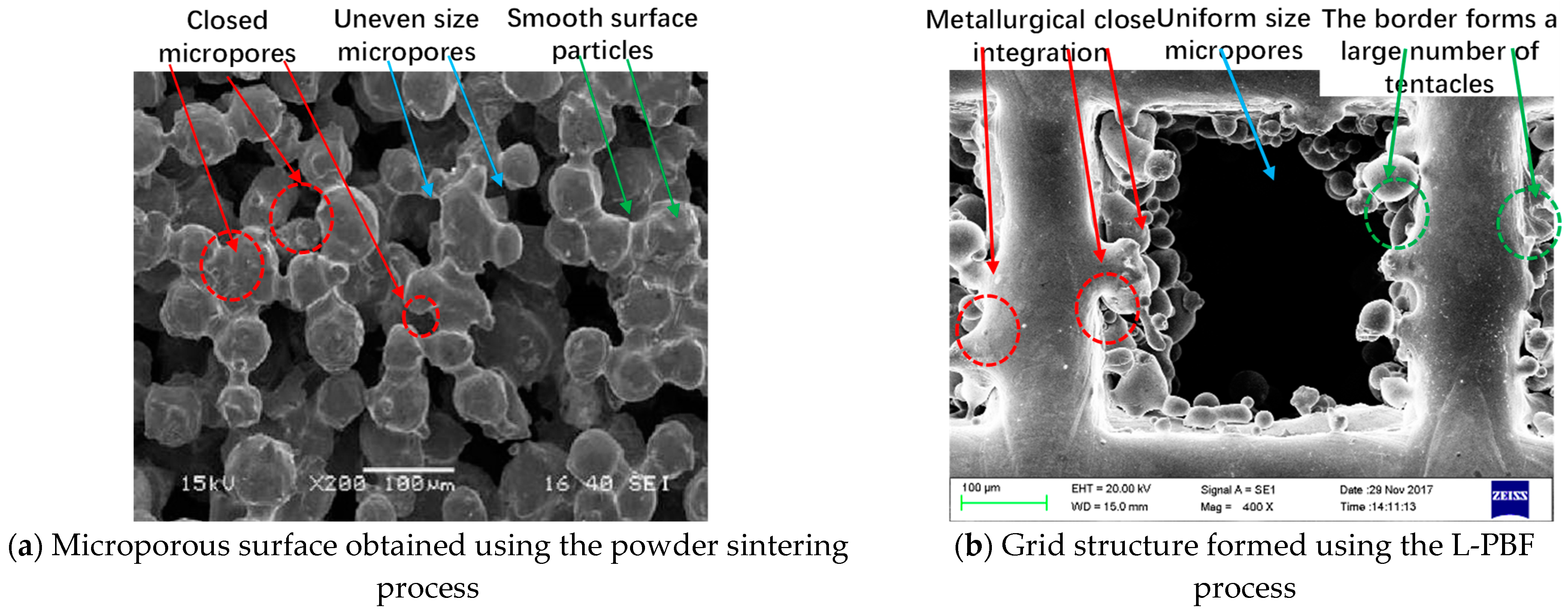
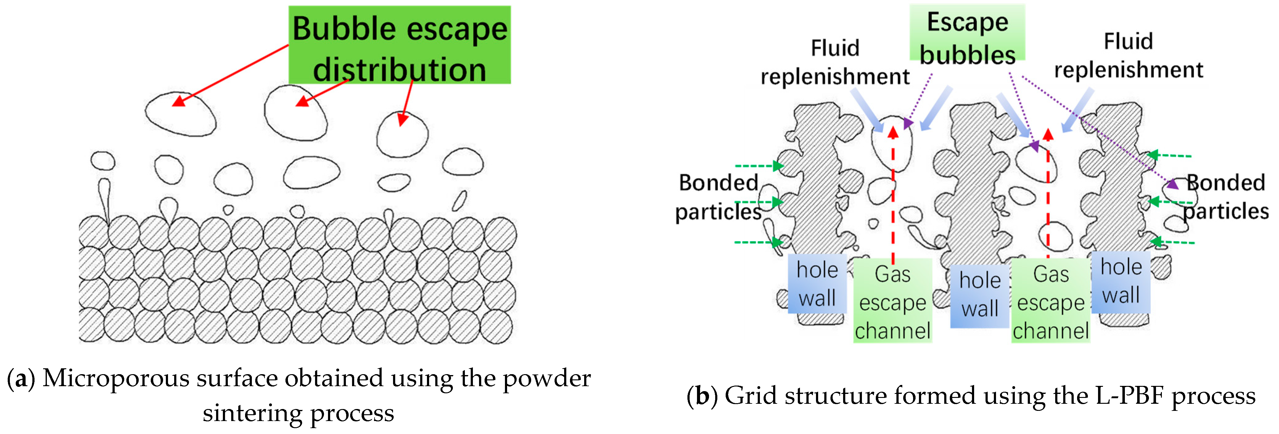
4.3. Comparison of the Boiling Heat Transfer Mechanisms of Grid Structure Samples and Powder-Sintered Samples

The results of the boiling heat transfer performance analysis of the grid structures presented in the previous section are compared with the corresponding results for the powder sintered microporous samples in this section. Powder sintering is a simple and efficient process for manufacturing microchannels, but it cannot accurately control microchannel size. Therefore, sintered samples tend to exhibit large variations in pore size and uneven microchannel distribution, which hinders the improvements of the boiling heat transfer performance. With L-PBF, the precise control of microchannel size, minimal error in pore size, and a uniform pore distribution can be achieved, which provides a meaningful approach for adjusting pore size parameters and improving boiling heat transfer performance. For this reason, the difference between the boiling heat transfer performance of microchannel grid structures prepared using the L-PBF method and the traditional powder sintering process was fully analyzed in this study. The morphologies of the powder-sintered microporous surface and the L-PBF-formed grid structure is shown in Figure 11a,b. The powder-sintered sample was prepared by mixing a 30% low melting point powder and an iron powder and then keeping them at a sintering temperature of 950 °C for 30 min, followed by cooling in a furnace. After sintering, microchannels with different shapes were formed inside the powder. Some of the microchannels were connected, but some were closed and had poor size uniformity. The L-PBF-formed grid structure was prepared using 240 W of laser power and a 0.5 mm hatch distance. The grid structure exhibited microchannels with uniform sizes, and the microparticles combined with the wall surface in a melted form and extended outward with antennal structures.
Furthermore, it could be seen that the characteristics of boiling heat transfer enhanced by the powder-sintered microporous surface and the L-PBF-formed grid structure were slightly different. As shown in Figure 12a, many tiny pores existed between the powder particles of the sintered microporous surface, which tended to produce dense bubbles as potential nucleation sites. When the heat was transferred from the particles to the liquid membrane of the small bubbles, the liquid membrane absorbed the heat and evaporated and the bubbles grew until they escaped from the holes and took away the heat. When the bubbles left the porous layer, the tiny pores could only replenish the liquid via a large capillary force [16].
In contrast, as shown in Figure 12b, the L-PBF-formed grid structure had pores with larger sizes, more regular shapes, and dense pore walls, mostly relying on the coarse pore walls and bonded powder particles to form the nucleation sites. Therefore, the grid structure had a low density of nucleation sites, but the numerous large holes provided good steam channels to ensure that steam could escape under a small resistance, which facilitated bubble escape and improved the boiling heat transfer efficiency. Furthermore, the large pores provided excellent channels for liquid replenishment. When the heat flux was high, too many bubbles were produced in boiling and formed a gas film around the grid structure, reaching the CHF point. However, timely liquid replenishment was able to delay this phenomenon.

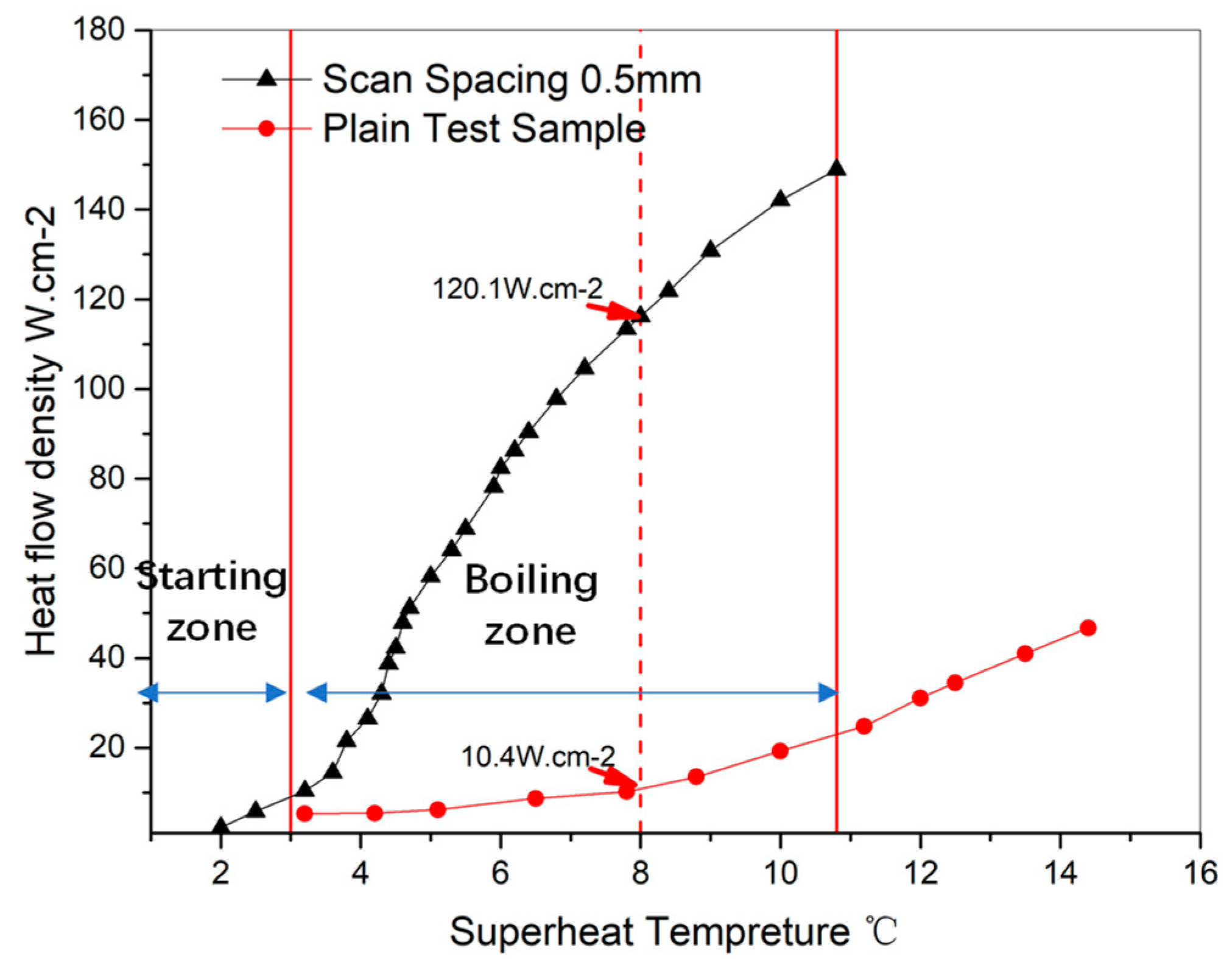
4.4. Comparison of the Boiling Heat Transfer Characteristics between a Grid Structure and Plain Test Sample

According to the boiling heat transfer test principle and experimental setup described in Section 4.1, a pool boiling heat transfer experiment was conducted with deionized water. The saturated boiling curves of the grid structure (240 W of laser power; 0.5 mm of hatch distance) and a traditional heat transfer plate were compared. Obviously, the grid structure enhanced the pool boiling heat transfer, exhibiting a CHF that was more than 10 times higher than that corresponding to the plain sample. In particular, at the superheat temperature of 8 °C, the CHF of the grid sample was 120.1 W·cm−2, that of the 316L SSL plain sample formed by the authors of this article was merely 10 W·cm−2, that of the plain copper alloy sample formed by Xu was 12 W·cm−2 [6], that of the plain copper alloy sample formed by Liu was 10.5 W·cm−2 [14], and that of the plain 316SSL sample formed by Zhang was 22 W·cm−2 [24]. As shown in Figure 13, the wall temperature rapidly rose with the increase in heat flux when it was low because the heat transfer medium was mainly a single-phase liquid with a poor heat transfer capacity. Therefore, when the heat load slightly increased, the wall temperature rapidly rose. At this stage, the saturated boiling curves of the grid structure and the plate showed no significant differences. However, when the heat flux increased to 20 W·cm−2, the rate of increase in the wall temperature of the grid structure significantly decreased and an inflection point appeared in the boiling curve, with boiling occurring on the wall surface. At this stage, the wall temperature of the plate still rapidly rose.

5. Conclusions

In this study, the boiling heat transfer performance of grid structures was analyzed. The main contributions of the study are summarized as follows:
(1)
Using 316 L stainless steel powder, an L-PBF-forming experiment of grid structures was conducted. The pore morphology and structural parameters of the grid structures, formed using different processing parameters, were obtained via microscopic observation and image processing. The effects of the scan spacing and laser power on the pore morphology, hydraulic diameter, and open porosity of the grid structure were studied. According to the characteristics of the macroporous structure of the grid parts, the internal porosity of the metal grid parts varied from 5% to 50% depending on the scanning spacing. The macroporosity of the surface was consistent with the macroporosity of the internal grid structure.
(2)
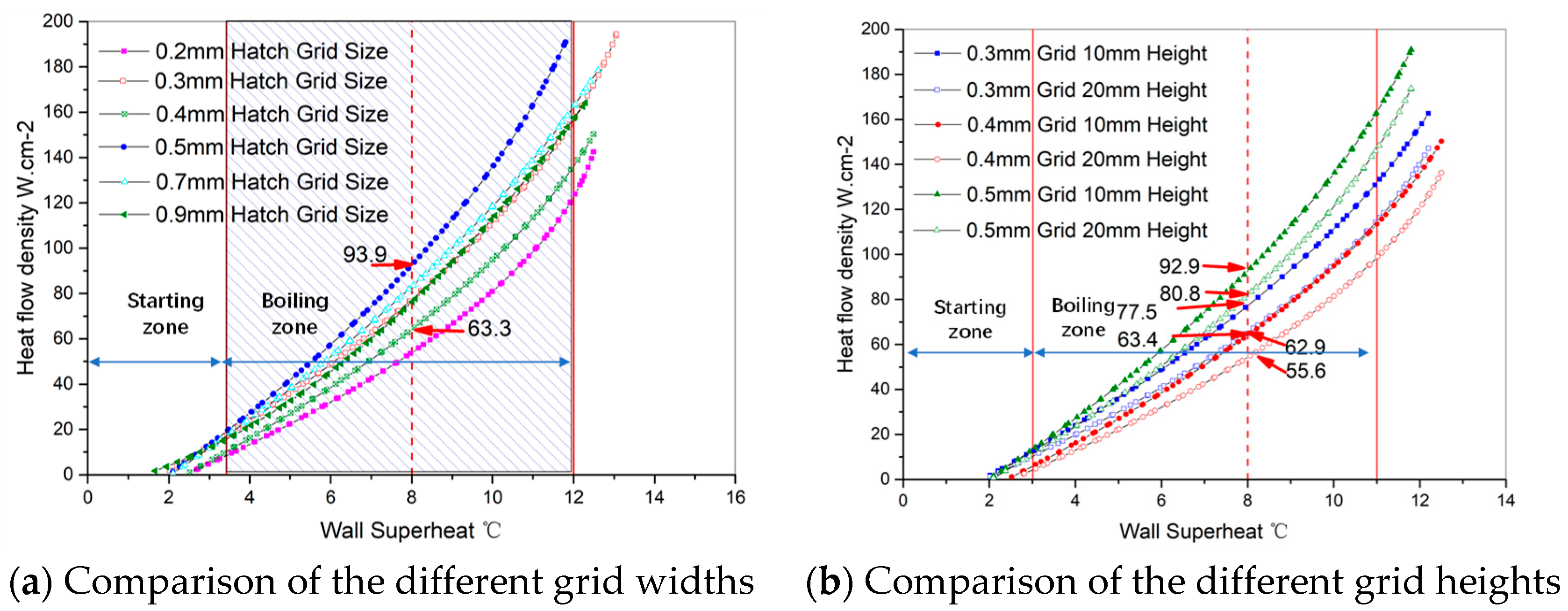
Grid samples with different scan spacings were experimentally compared, demonstrating that among different widths, the 0.5 mm sample exhibited the best critical heat transfer performance with a CHF of 10–27% higher than those of the other four samples (minimum of 63.3 W·cm−2 and maximum of 93.9 W·cm−2) at the wall superheat temperature of 8 °C. For samples with a grid width greater than 0.5 mm, the boiling slightly decreased by <5%. This was because when the grid width exceeded 0.5 mm, the flow resistance decreased, the high-temperature flow rate increased, and the bubbles produced by the wall synapses reduced, thus causing a decrease in the heat flux carried away by the bubbles.
(3)
When the grid width was further increased, the flow resistance and the bubble synapse generation effects tended to converge where the boiling heat transferred in only a single phase along the medium wall thickness direction and the optimal two-phase heat transfer effect could not occur by bubble growth and collapse.

Author Contributions

Conceptualization, B.Q. and P.L.; methodology, J.Z.; software, B.Q.; validation, B.Q., H.F. and G.L.; formal analysis, H.F.; investigation, P.L.; resources, B.Q.; data curation, H.F.; writing—original draft preparation, P.L.; writing—review and editing, B.Q.; visualization, H.F., G.L., J.Z.; project administration, G.L.; funding acquisition, B.Q. All authors have read and agreed to the published version of the manuscript.

Funding

This study was funded by the Key Project of Chinese National Programs for Fundamental Research and Development- Model Processing and Process Planning Software Project for Additive Manufacturing (2018YFB1105300)- Universal Full-dimension Digital Model Project (2018YFB1105301) and National Natural Science Foundation of China (51705307), Open Project Program of the State Key Lab of CAD&CG (Grant No. A2015).

Institutional Review Board Statement

Not applicable.

Informed Consent Statement

Not applicable.

Data Availability Statement

Not applicable.

Conflicts of Interest

The authors declare no conflict of interest.

References

  1. Qu, Y.; Wang, S.; Tian, Y. A review of thermal performance in multiple evaporators loop heat pipe. Appl. Therm. Eng. 2018, 143, 209–224. [Google Scholar] [CrossRef]
  2. Vasiliev, L.L. Micro and miniature heat pipes-Electronic component coolers. Appl. Therm. Eng. 2008, 28, 266–273. [Google Scholar] [CrossRef]
  3. Mudawar, I. Recent Advances in High-Flux, Two-Phase Thermal Management. J. Therm. Sci. Eng. Appl. 2013, 5, 021012. [Google Scholar] [CrossRef]
  4. Das, A.K.; Das, P.K.; Saha, P. Performance of different structured surfaces in nucleate pool boiling. Appl. Therm. Eng. 2009, 29, 3643–3653. [Google Scholar] [CrossRef]
  5. Dong, L.; Quan, X.; Cheng, P. An experimental investigation of enhanced pool boiling heat transfer from surfaces with micro/nano-structures. Int. J. Heat Mass Transf. 2014, 71, 189–196. [Google Scholar] [CrossRef]
  6. Xu, P.; Li, Q.; Xuan, Y. Enhanced boiling heat transfer on composite porous surface. Int. J. Heat Mass Transf. 2015, 80, 107–114. [Google Scholar] [CrossRef]
  7. Surtaev, A.S. Heat transfer and crisis phenomena at pool boiling of liquid nitrogen on the surfaces with capillary-porous coatings. Int. J. Heat Mass Transf. 2017, 108, 146–155. [Google Scholar] [CrossRef]
  8. Surtaev, A. Structured capillary-porous coatings for enhancement of heat transfer at pool boiling. Appl. Therm. Eng. 2018, 133, 532–542. [Google Scholar] [CrossRef]
  9. Kotthoff, S.; Gorenflo, D.; Danger, E.; Luke, A. Heat transfer and bubble formation in pool boiling: Effect of basic surface modifications for heat transfer enhancement. Int. J. Therm. Sci. 2006, 45, 217–236. [Google Scholar] [CrossRef]
  10. Chang, J.Y.; You, S.M. Boiling heat transfer phenomena from microporous and porous surfaces in saturated FC-72. Int. J. Heat Mass Transf. 1997, 40, 4437–4447. [Google Scholar] [CrossRef]
  11. Mohamed, S.E.; Amir, F.A. Enhanced nucleate boiling on copper microporous surfaces. Int. J. Multiph. Flow 2010, 36, 780–792. [Google Scholar]
  12. Suazlan, M.A.; Shoji, M.; Fumiki, S. Effects of heater orientation on critical heat flux for nanoparticle-deposited surface with honeycomb porous plate attachment in saturated pool boiling of water. Int. J. Heat Mass Transf. 2016, 102, 1345–1355. [Google Scholar]
  13. Deng, D.X.; Feng, J.Y.; Huang, Q.S.; Tang, Y.; Lian, Y. Pool boiling heat transfer of porous structures with reentrant cavities. Int. J. Heat Mass Transf. 2016, 99, 556–568. [Google Scholar] [CrossRef]
  14. Liu, H.L.; Zhang, C.; Wang, J.; Zhang, L. Critical heat flux enhancement using composite porous structure produced by selective laser melting. Appl. Therm. Eng. 2021, 197, 117396. [Google Scholar] [CrossRef]
  15. Li, C.H.; Li, T.; Hodgins, P.; Hunter, C.N.; Voevodin, A.A.; Jones, J.G.; Peterson, G.P. Comparison study of liquid replenishing impacts on critical heat flux and heat transfer coefficient of nucleate pool boiling on multiscale modulated porous structures. Int. J. Heat Mass Transf. 2011, 54, 3146–3155. [Google Scholar] [CrossRef]
  16. Arvind, J.; Satish, G.K. Enhanced pool boiling for electronics cooling using porous fin tops on open microchannels with FC-87. Appl. Therm. Eng. 2015, 91, 426–433. [Google Scholar]
  17. Seol, H.K.; Gi, C.L.; Jun, Y.K.; Moriyama, K.; Kim, M.H.; Park, H.S. Boiling heat transfer and critical heat flux evaluation of the pool boiling on micro structured surface. Int. J. Heat Mass Transf. 2015, 91, 1140–1147. [Google Scholar]
  18. Ji, X.B.; Xu, J.L.; Zhao, Z.W.; Yang, W. Pool boiling heat transfer on uniform and non-uniform porous coating surfaces. Exp. Therm. Fluid Sci. 2013, 48, 198–212. [Google Scholar] [CrossRef]
  19. Scott, G.L.; Massoud, K. Pool-boiling CHF enhancement by modulated porous-layer coating: Theory and experiment. Int. J. Heat Mass Transf. 2001, 44, 4287–4311. [Google Scholar]
  20. Min, D.H.; Hwang, G.S.; Usta, Y.; Cora, O.N.; Koc, M.U.; Kaviany, M. 2-D and 3-D modulated porous coatings for enhanced pool boiling. Int. J. Heat Mass Transf. 2009, 52, 2607–2613. [Google Scholar] [CrossRef]
  21. Ahn, H.S.; Gunyeop, P.; Kim, J.M. The effect of water absorption on critical heat flux enhancement during pool boiling. Exp. Therm. Fluid Sci. 2012, 42, 187–195. [Google Scholar] [CrossRef]
  22. Yadroitsev, I.; Shishkovsky, I.; Bertrand, P.; Smurov, I. Manufacturing of finestructured 3D porous filter elements by selective laser melting. Appl. Surf. Sci. 2009, 255, 5523–5527. [Google Scholar] [CrossRef]
  23. Wong, K.K.; Leong, K.C. Saturated pool boiling enhancement using porous lattice structures produced by Selective Laser Melting. Int. J. Heat Mass Transf. 2018, 121, 46–63. [Google Scholar] [CrossRef]
  24. Chi, Z.; Li, Z.; Hong, X.; Pei, L.; Bo, Q. Performance of pool boiling with 3D grid structure manufactured by selective laser melting technique. Int. J. Heat Mass Transf. 2019, 128, 570–580. [Google Scholar]
  25. Bagheri, Z.S.; Melancon, D.; Liu, L.; Johnston, R.B.; Pasini, D. Compensation strategy to reduce geometry and mechanics mismatches in porous biomaterials built with Selective Laser Melting. J. Mech. Behav. Biomed. Mater. 2016, 70, 17–27. [Google Scholar] [CrossRef] [Green Version]
  26. Ameli, M.; Agnew, B.; Leung, P.S.; Ng, B.; Sutcliffe, C.J.; Singh, J.; McGlen, R. A novel method for manufacturing sintered aluminium heat pipes (SAHP). Appl. Therm. Eng. 2013, 52, 498–504. [Google Scholar] [CrossRef]
  27. Xu, Z.G.; Qu, Z.G.; Zhao, C.Y.; Tao, W.Q. Experimental correlation for pool boiling heat transfer on metallic foam surface and bubble cluster growth behavior on grooved array foam surface. Int. J. Heat Mass Transf. 2014, 77, 1169–1182. [Google Scholar] [CrossRef]
  28. Qian, B.; Fan, H.R.; Liu, G.; Zhang, J.; Li, P. Self-Supporting Microchannel Liquid-Cooled Plate for T/R Modules Based on Additive Manufacturing: Study on Its Pass Design, Formation Process and Boiling Heat Transfer Performance. Metals 2021, 11, 1731. [Google Scholar] [CrossRef]
  29. Qian, B.; Fan, H.R.; Liu, G.; Zhang, J.; Li, P. Microchannel Liquid-Cooled Heat Exchanger Based on a Nonuniform Lattice: Study on Structure Calculation, Formation Process, and Boiling Heat Transfer Performance. Materials 2021, 14, 7248. [Google Scholar] [CrossRef]
Figure 1. The principle of forming a grid structure using the L-PBF technique; transverse and longitudinal scanning was alternately performed, forming a large number of neatly arranged square holes.
Energies 15 01779 g001
Figure 2. The L-PBF experimental facility, which consisted of a host, a laser system, a cooling system, a control system, and a gas protection system.
Energies 15 01779 g002
Figure 3. SEM image of the 316L stainless steel powder [28].
Energies 15 01779 g003
Figure 4. Grid structures formed using different scan spacings.
Energies 15 01779 g004
Figure 5. SEM images of the grid structures formed with 200 W of laser power and at different scan spacings.
Energies 15 01779 g005
Figure 6. Images of the polished grid structures formed with a 0.3 mm scan spacing and different laser power values.
Energies 15 01779 g006aEnergies 15 01779 g006b
Figure 7. Comparison of the hydraulic diameter of the grid structures. (a) Hydraulic diameters of the grid structures formed by different scan spacings. (b) Hydraulic diameters of the grid structures formed using different laser powers.
Energies 15 01779 g007
Figure 8. Comparison of the open porosities of the grid structures. (a) Open porosities of the grid structures formed by different scan spacings. (b) Open porosities of grid structures formed using different laser powers.
Energies 15 01779 g008
Figure 9. Schematic of boiling heat transfer experimental equipment including a boiling heat transfer test device, an auxiliary heating control device, a main heating control device, and a data acquisition device [29].
Energies 15 01779 g009
Figure 10. Saturated boiling curves of the grid structures with different widths and heights.
Energies 15 01779 g010
Figure 11. SEM images of the microporous grid structures.
Energies 15 01779 g011
Figure 12. Enhancement of the boiling heat transfer process due to the microporous structures.
Energies 15 01779 g012
Figure 13. Saturated boiling curves corresponding to the grid structure and plain test sample.
Energies 15 01779 g013
Table 1. Primary working parameters of the laser [28].
ParameterSetting
Rated output power (W)250
Working modeContinuous/Modulated
Center wavelength (nm)1080
Output power fluctuation<3%
Minimum spot diameter (mm)0.06
Table 2. Chemical composition and particle size distribution of the 316L stainless steel powder [28].
ElementAssay Value/wt. %ElementAssay Value/wt. %Particle Size DistributionAssay Value/wt. %
Cr16.79Mn0.20D1023.1
Mo2.42S0.011D5035.3
Ni10.66P0.025D9053.3
Si1.00O0.0247
Table 3. Forming process parameters for the grid structures using L-PBF.
No.Laser Power (W)Scan Spacing (mm)Scanning Speed (mm∙s−1)Layer Thickness (mm)
12000.15500.03
22000.2
32000.4
42000.5
51800.3
62000.3
72200.3
82400.3
92400.1
102400.2
112400.4
122400.5
132000.7
142200.9
152400.9
Publisher’s Note: MDPI stays neutral with regard to jurisdictional claims in published maps and institutional affiliations.

