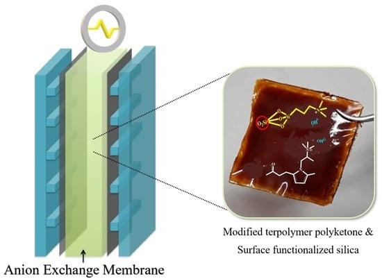
Article

Enhanced OH Conductivity for Fuel Cells with Anion Exchange Membranes, Based on Modified Terpolymer Polyketone and Surface Functionalized Silica

Department of Civil, Environmental and Mechanical Engineering, University of Trento, Via Mesiano, 77, 38123 Trento, Italy
*
Author to whom correspondence should be addressed.
Energies 2022, 15(5), 1953; https://doi.org/10.3390/en15051953
Submission received: 18 January 2022 / Revised: 13 February 2022 / Accepted: 3 March 2022 / Published: 7 March 2022
(This article belongs to the Section D2: Electrochem: Batteries, Fuel Cells, Capacitors)

Abstract

:
Several modified terpolymer polyketones (MPK) with N-substituted pyrrole moieties in the main chain and quaternized amine in the side group were synthesized for use as anion exchange membranes for fuel cells. The moieties were carried by SiO2 nanoparticles through surface functionalization (Si–N), which were added to the membranes to enhance their overall properties. On increasing the amount of modified silica from 10% to 60% wt/of MPK, there was an increase in Si–N and a corresponding threefold increase in the hydroxide conductivity of the membrane. The MPK–SiN (60%) exhibited a superior ionic conductivity of 1.05 × 10⁻¹ S.cm−1 at 120 °C, a high mechanical stability, with a tensile strength of 46 MPa at 80 °C. In strongly alkaline conditions (1 M KOH, 216 h at 80 °C), the membranes maintained about 70% of the conductivity measured in a usual environment. Fuel cell performance at 80 °C showed a peak power density of 133 mW·cm−2, indicating that using surface-functionalized SiO2 is a simple and effective way to enhance the overall performance of anion exchange membranes in fuel cell applications.

Graphical Abstract

1. Introduction

Among the sources of renewable clean energy, hydrogen is receiving increasing attention from policy makers. The European Commission recently presented the European Green Deal [1] with the main objective of reaching net-zero emissions by 2050 by scaling up of the use of hydrogen in various sectors.
Renewable energy sources such as solar energy and wind energy are unstable and intermittent during generation, making these valuable electrical energies difficult to exploit continuously and stably [2]. Electricity generation from a solar plant requires the use of fossil fuels when solar energy is low in winter and on cloudy days, and a thermal storage system when solar radiation exceeds the expected standard level. Similar needs arise with wind farms [3]. On the other hand, hydrogen can also be produced and used continuously in small plants or cells that have no contraindications from the point of view of fuel accumulation. Among the different possible applications of hydrogen, a key role is played by fuel cell (FC) technology, which represents an efficient way to convert hydrogen, and possibly other clean fuels, into electricity. In particular, the development of anion-exchange membrane fuel cells (AEMFCs) [4,5,6] has attracted increasing interest due to the use of non-metal catalysts such as Pd, Ag, Ni, and Fe–N/C [6,7,8]. For this same reason, AEMFCs are significantly reducing the main costs of FC systems by comparison with proton exchange membrane fuel cells (PEMFCs) [9,10]. The main component of AEMFCs is the electrolyte [11,12,13], composed of an organic polymeric backbone onto which positively charged (cationic) functional groups are bound covalently, both as side chains or directly onto the main chain [14]. The electrolyte separates the electrodes and enables the selective transport of hydroxide anions (OH) from the cathode to the anode, while water diffuses in the opposite direction. An ideal anion exchange membrane (AEM) must have a high ionic conductivity in chemically aggressive environments, a good resistance to high temperatures, and long-term durability under alkaline conditions. It must also be able to withstand mechanical stresses without any significant changes in its conductive properties.
The most common solution is to introduce more ion-exchange groups in AEMs to achieve a higher performance in AEMFCs, but this process causes extreme swelling and a deterioration in the mechanical properties of the AEMs. To overcome this issue, efforts to incorporate inorganic additives such as SiO2 [15], ZrO2 [16,17], and TiO2 [18] in the polymer matrix have proved effective. The oxide particles form an inorganic backbone on which the organic part binds through interactions between the surface hydroxyls and the functional groups of the polymer, also forming hydrogen bonds in the presence of oxygen-based functional groups or weaker interactions in their absence [19]. This approach results in a lower ionic conductivity and membrane permeability; however, as a consequence of the presence of fillers in the hydrophobic domains, which reduce the free volume for water uptake [20]. Decreased ionic conductivity is a disadvantage for AEMs in fuel cell applications, unlike the case of membranes with a low permeability to gas/active species. According to Sue et al. [19], fillers create hydrophilic domains dynamically crosslinked with the polymer host: smaller hydrophilic domains coincide with less water uptake [19], and this hinders the passage of the species through the ionic channels. Functionalizing the inorganic fillers by attaching bigger ionic groups (e.g., ammonium cations) to the surface of inorganic particles [21] could help to maintain a good ionic conductivity only reducing permeability.
These types of membranes have various advantages, such as the ability to combine the properties of different components, achieving excellent mechanical and thermal properties, as well as improving their hydration capacity.
We recently prepared an anion exchange membrane based on polyamine (obtained by chemically modifying alternating aliphatic polyketone (PK) with primary amine) with the incorporation of amine-functionalized silica [22]. PK is a promising polymer because the starting raw materials (carbon monoxide and ethylene monomers) are commonly available and inexpensive. Using PK is also an outstanding strategy for synthesizing functional polymers with pendant-charged aromatic groups through one of the most classical approaches, known as the Paal–Knorr reaction [23,24,25]. In our previous work, a thorough investigation of the chemical features of modified silica and its interaction with modified PK was conducted using Fourier transform infrared spectroscopy (FTIR) and nuclear magnetic resonance spectroscopy (NMR). The impact of modified silica on the thermal properties of modified polyketones based on anion exchange membranes was also investigated: They showed an excellent thermal stability up to 300 °C with only 1% of weight loss [22].
In the present work, to investigate the effect of the modified silica content on the properties of AEMs in terms of their ionic conductivity, water uptake, ion exchange capacity, swelling ratio, alkaline stability, and mechanical properties, AEMs were synthesized with increasing amounts of modified SiO2 as the hydrophilic phase and ion conductors. A membrane–electrode assembly (MEA) was prepared using the material showing the highest conductivity (MPK–SiN [60%]), and it was tested in an alkaline fuel cell operated at 80 °C with H2 and O2 feed gases.

2. Materials and Methods

2.1. Materials

The commercial polyketone (alternating PK of ethylene, propylene and carbon monoxide; M330A, Mw = 185,000 g/mol) was received from Hyosung Co. Ltd. (Seoul, South Korea). 1,1,1,3,3,3-hexafluoroisopropanol (99%), 1,2-diaminopropane (99%), 3-aminopropyltriethoxysilane (99%), absolute ethanol, ammonium hydroxide (28–30%), ethylene carbonate (98%), iodomethane (99%) methanol (99.8%), potassium hydroxide (90%), and trimethylamine (99%) were purchased from Sigma-Aldrich. Silica powder with an average diameter of 5–20 nm was used (Sigma-Aldrich). Distilled water was used in all procedures. All reagents and solvents were used as received.

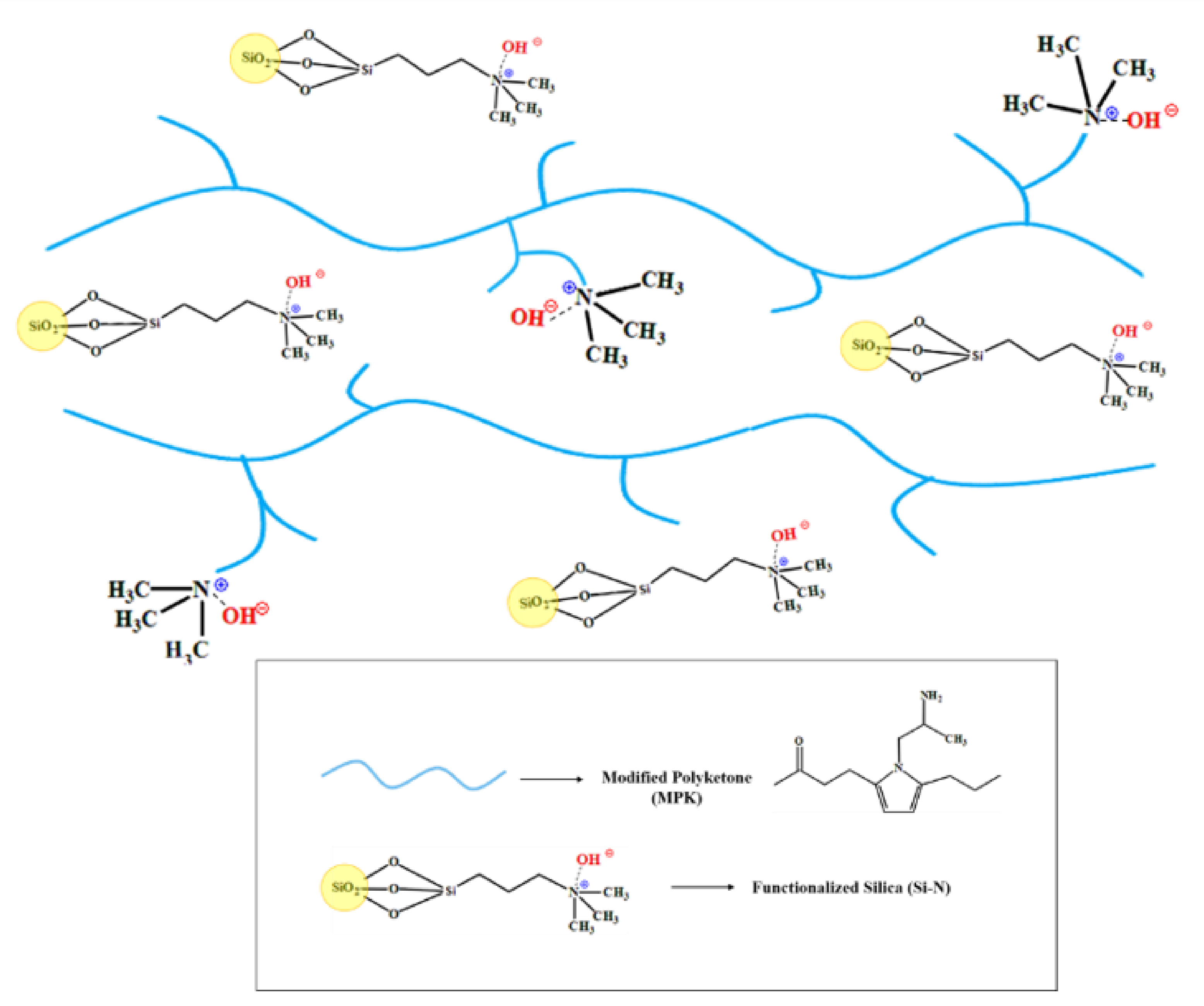
2.2. Preparation of Membranes

Amine functionalized silica (Si–N) was synthesized by the co-condensation of 3-aminopropyltriethoxysilane (APTES) using the sol–gel method. Terpolymer polyketone (ethylene, propylene, and carbon monoxide) was chemically modified by Paal–Knorr reaction. A detailed account of the silica functionalization and modification of the polyketone (MPK) is provided in the Supplementary Materials Sections S1 and S2.
Membranes were prepared by adding modified silica to MPK dissolved in 1,1,1,3,3,3-hexafluoroisopropanol (HFIP). The amounts added were 10, 30, and 60 wt% with respect to the polymer. The sols obtained were stirred for 1 h at 40 °C, and ethylene carbonate was added as a plasticizer, in the amount of 30% with respect to the weight of the sol. Then, the sols were treated with NH4OH vapor, maintained in an ultrasonic bath at 40 °C for about 30 min, left stirring overnight at 40 °C, and finally cast in a mold. The membrane obtained was named MPK–SiN. The amount of modified silica was optimized at 60 wt%; beyond this value, there was evidence of brittle fracture of an excessively stiff material after casting the solution.
To run a methylation reaction, the MPK–SiN membrane was immersed in iodomethane solution for 24 h, then washed thoroughly with deionized water. The methylated membrane was changed to the hydroxide ion form in 1 M KOH solution for 1 h. This process was repeated three times. The MPK–SiN in OH form was rinsed with distilled water and stored in distilled water under a nitrogen atmosphere to prevent hydroxide anions from being converted into carbonate and bicarbonate species through contact with atmospheric carbon dioxide.

2.3. Measurements and Characterizations

An elemental analysis was carried out using a LECO-CHN628 instrument (Saint Joseph, MI, USA) with a combustion technique to ascertain the nitrogen content per gram in the modified polyketone [26,27,28]. Scanning electron microscopy (SEM) imaging was performing with a Coxem EM-30AX instrument (Coxem, Daejeon, Korea) using secondary electrons (SE) and backscattered electrons (BSE) and operated at 10 kV accelerating voltage. A thermo-gravimetric analysis (TGA) was performed from 25 °C to 600 °C in N2 with a heating rate of 10 °C/min, using a Labsys SETARAM thermobalance (Caluire, France).
The electric resistance of the membranes was measured by impedance spectroscopy using a SP-150 BioLogic (Seyssinet-Pariset, France). All the samples were fully hydrated in deionized water for at least 24 h prior to the conductivity measurement. A membrane sample (a disk 1.27 cm in diameter) was sandwiched between two circular gold electrodes inside a CESH sample-holder, which was placed inside a glovebox filled with nitrogen to prevent carbonation. Conductivity in temperature (from 30 °C to 120 °C, in 10 °C steps) was measured with an intermediate temperature system (ITS) from BioLogic, connected to the SP-150 instrument. The measurement was obtained at frequencies ranging from 1 MHz to 100 Hz with a voltage of 0.01 V. Conductivity was calculated as:
σ   S · cm 1 = t R × A  
where t is the thickness of the sample (cm), R is the resistance (Ω), and A (cm2) is the area. The activation energy (Ea) of conductivity was calculated from the linear Arrhenius relationship between ln σ and 1000/T:
E a = b . R · E a = b · R
where b is the slope of the linear regression of ln σ versus 1000/T plots, and R is the gas constant.
To measure the water uptake, the membranes were vacuum-dried at 40 °C for 24 h, then immersed in distilled water for 24 h. The membrane samples were removed from the water and weighed immediately after they had been wiped with tissue paper. The reported measurements are based on a sample about 20 mm × 20 mm in size, and were obtained at 30, 40, 50, 60, 70, and 80 °C. The temperature was controlled by means of a thermostatic water bath. The membrane’s water uptake was calculated from the difference in weight between the wet (Wwet) and dry (Wdry) samples:
W a t e r   u p t a k e   % = ( W w e t W d r y ) M d r y × 100
The swelling ratio (SR) was determined from the difference between the wet (lwet) and dry (ldry) diameters of the membrane samples (20 mm long by 20 mm wide) after immersion in water at 20, 30, 40, 50, 60, 70, and 80 °C for 24 h according to the definition:
S w e l l i n g   r a t i o   % = ( l w e t l d r y ) l d r y × 100 %
The ion exchange capacity (IEC) of the membrane was measured by immersing it in 30 mL of 0.01 M HCl solution for 24 h. The solution was then titrated with 0.01 M NaOH solution, using phenolphthalein as an indicator. The IEC was calculated using the equation:
I o n   e x c h a n g e   c a p a c i t y   mmol g =   [ ( V 0 , N a O H V N a O H · C ] M d r y
where V0,NaOH and VNaOH are the volumes of NaOH solution consumed for back titration without and with the membrane, respectively; C is the concentration of NaOH solution; and Mdry is the mass of the dry membrane.
The alkaline stability of the membrane was examined by immersing a membrane sample in a 1 M KOH solution at 80 °C for 216 h. Then, the membrane was washed with distilled water to remove the residual KOH. The degradation of the membrane sample was assessed by measuring the change in hydroxide conductivity.
Fourier transform infrared spectroscopy (FTIR) was performed using a Perkin Elmer spectrometer, averaging 16 scans with a resolution of 2 cm−1 in the wavenumber range between 650 and 4000 cm−1.
The mechanical properties of the membranes without and with modified silica (MPK and MPK–SiN (60%) were investigated using an EXSTAR TMA/SS6000 thermo-mechanical analyzer (Seiko Instruments Inc. Chiba, Japan) at 25 °C and 80 °C. The rate of extension applied was 0.5 mm/min up to 5 mm of maximum extension. The measurements were repeated at least 6 times on membrane samples about 0.1 mm-thick, 0.5 mm-wide, and 5 mm-long.
MPK and MPK-SiN (60%) membranes in the hydroxide form were used to fabricate the MEAs for a single H2/O2 fuel cell test. The cathode (0.5 mg/cm2 of 60% PtC) and anode (0.5 mg/cm2 of PtRu) were prepared by spraying catalyst ink on the carbon paper and post-coated ionomer (Fumion FAA-3, 10 wt% in NMP). An MEA of the MPK–SiN (60%) membrane with an active area of 4 cm2 and thickness of 0.1 mm was obtained by pressing the cathode and anode onto the membrane under 0.4 MPa. The fuel cell was assessed with humidified (100% relative humidity) H2 and O2 gases at 80 °C using a single cell (H-TEC Education’s 1-Cell). The flow rates of hydrated H2 and O2 were set at 50 mL/min, backpressure of 0.5 barg. The schematics of the fuel cell measurement is shown in Scheme 1.

3. Results and Discussion

The extent of carbonyl (1,4-dicarbonyl unit) conversion to heterocycle was calculated using elemental analysis, which showed that 58.62% of the carbonyl group was converted into the pyrrole ring. Detailed information and the calculations are provided in the Supplementary Materials Table S1 and Section S3. The degree of conversion depended strongly on the reaction time: the longer the reaction time, the greater the degree of conversion. A greater degree of conversion implies the presence of a larger number of functional groups or ion exchange sites capable of transporting the hydroxyl anions. It also negatively affects the mechanical properties of the membranes, so free-standing membranes cannot be obtained during casting. To overcome this problem, Si–N was incorporated into the MPK (with a low degree of conversion). The tail of modified silica (NH2) not only acted as an anion exchanger (as shown in Scheme 2) but also improved the overall performance of the membrane.

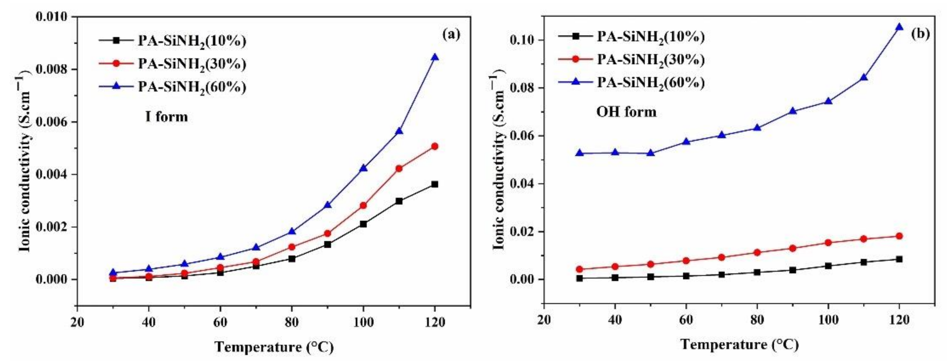
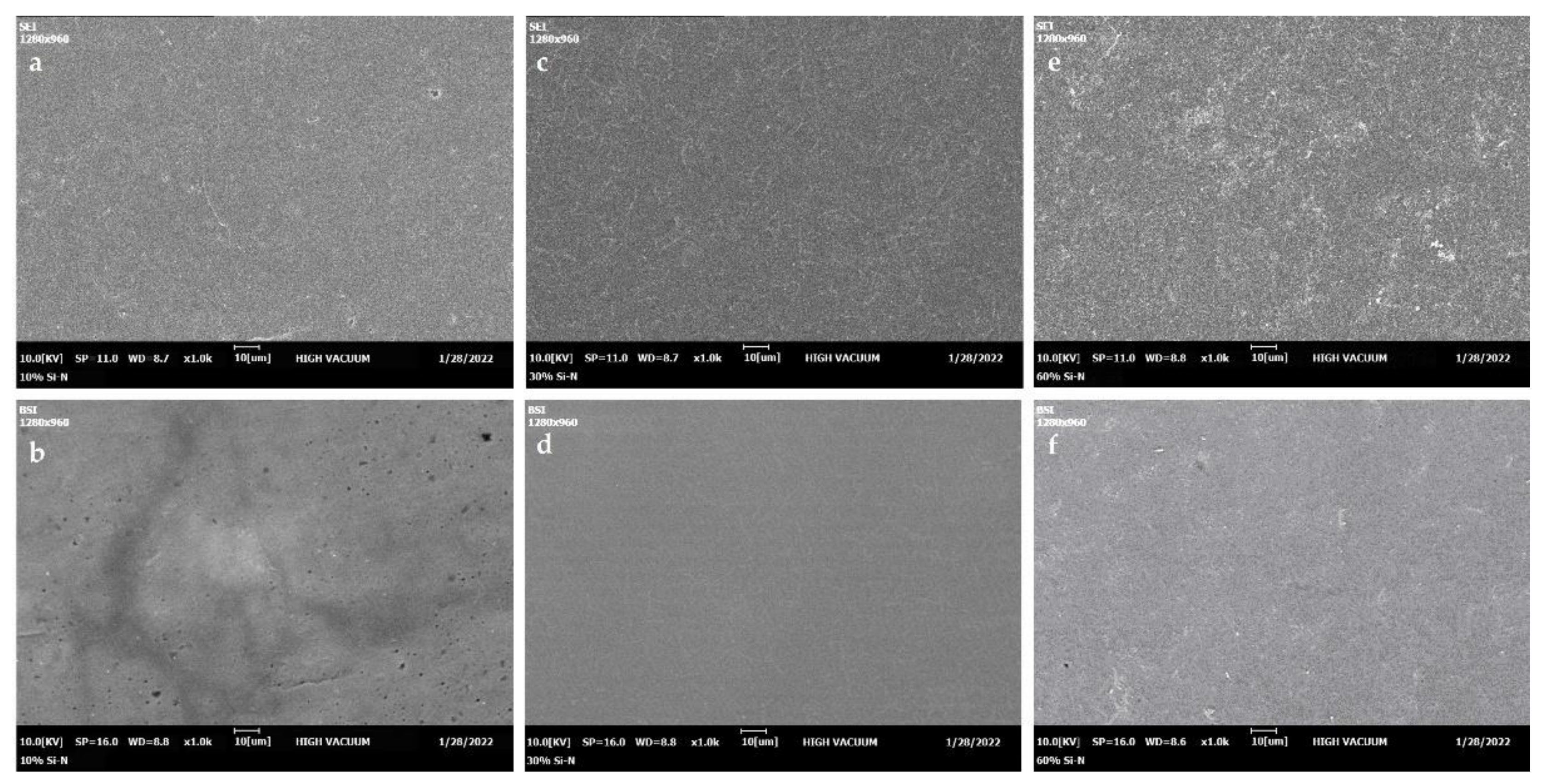
3.1. Conductivity and Morphology

The conductivity of the membranes as a function of temperature (30–120 °C) was measured on their iodide or hydroxyl forms, as shown in Figure 1, while their maximum values are listed in Table 1. The conductivity increases with the amount of Si–N (10%, 30%, or 60%). The lower percentage of modified silica (10%) had little impact on the ionic conductivity of the membrane was not significant because the anionic functional group of the membrane was mainly responsible for the conductivity. This impact increased with larger proportions of dopant (30%). At the highest percentage (60%), the tail of modified silica becomes dominant with respect to the matrix in the conduction mechanism, forming additional conducting routes. This could explain the significant enhancement in the conductivity of the membrane from 30% to 60% of dopant content. In other words, for higher proportions of dopant (60%), the conductivity is due not only to the anionic functional group of the membrane but also to the tail of modified silica. Conductivity benefits from the creation of stable pathways in the composite polymer–silica, lined with the ionic groups of the modified silica reinforcement. This occurs above a limit threshold which, from the graph, appears to be above 30% by weight of reinforcement. Below that limit, the conductivity channels are not formed so long and stable as to represent one of the main mechanisms of ionic conduction.
The groups (-N(CH3)3) of modified silica promote the charge carrier transport [22], provide a larger free volume (which improves ion transport due to the increased flexibility) and favor the formation of channels of water molecules adsorbed on the surface of the nanoparticles. The enhanced ionic conductivity is also attributable to hydrogen bonds between the functional groups of the polymer matrix and those of the modified silica. The presence of filler modifies the polymer chain arrangement, providing additional conducting pathways within the host polymer matrix. Figure 2a,c,e show the morphology of the membranes with the three different contents (10%, 30%, and 60 wt%) of modified silica, respectively. The images confirm that the surface is always homogeneous. Figure 2b,d,f show images of membranes obtained with backscattering electrons. The surface part with modified silica appears brighter. The membrane containing the lowest amount of silica is also the less uniform than the other two. In particular, the membrane with the highest content of Si–N groups is both uniform and more conductive, as it contains more polar groups.
The conductivity of the membranes increased with temperature. The highest conductivities of 8.4 × 10⁻³ S·cm−1 and 1.0 × 10⁻¹ S·cm−1 at 120 °C were achieved for MPK–SiN (60%) in I and OH form, respectively. These values are four times higher than those of membranes without modified silica (9 × 10⁻⁴ S·cm−1) [23], and this increase can be explained by the free-volume model. With higher temperatures, the free volume increases while the ion transferring channel becomes wider, and both prompt an increase in overall ion mobility [29,30]. It is also worth noting that the conductivity of the membrane in OH form is much greater than that of the one in I form. This is due to OH being more mobile than I [31,32]. The hydroxide OH transfer through the membrane is a key parameter for assessing AEMFC performance.
The Arrhenius plots of membrane conductivity (ln σ vs. 1000/T plots, in I and OH forms) are shown in the Supplementary Materials Figure S1. The conductivity shows a perfect linear trend, with a refined coefficient value indicating an ion hopping conduction mechanism. The calculated activation energy (Ea) and the conductivity values at 120 °C are shown in Table 1. The Ea values of the membrane in OH form are lower than those the membrane in I form. In fact, the enhanced thermal motion and the faster diffusion of OH with respect to I increased the ionic conduction at high temperatures, overcoming the activation energy for ion transport. The Ea of both types also increased with a reduction in Si–N content: The higher the Si–N content, the closer the functional groups, resulting in a lower-energy barrier. The membrane containing 10% of modified silica shows the highest Ea (32.3 kJ.mol−1), indicating a larger energy barrier along ion transport pathways.

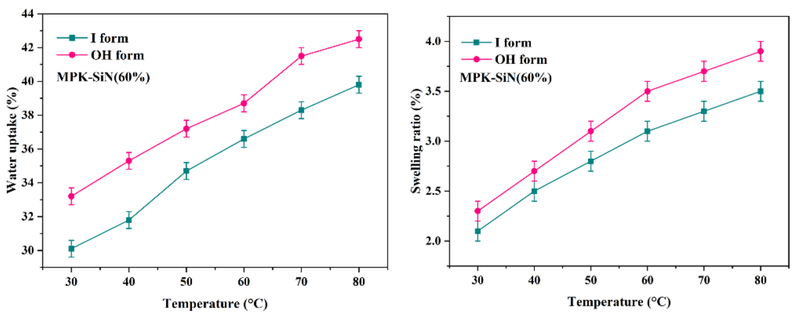
3.2. Water Uptake, IEC, and Swelling Ratio

The water uptake of AEMs is a key parameter affecting dimensional stability, ionic conductivity, and overall fuel cell performance [33]. Figure 3 shows the temperature dependence of the water uptake and swelling ratio of the MPK–SiN membranes at the highest ionic conductivity. The membranes’ water uptake correlates closely with their ion conductivity because water molecules act as means of transport: a greater water uptake was always evident for the membrane in OH form. A larger amount of Si–N groups also increased the water uptake, favoring the formation of a continuous transferring channel in the membranes, and justifying the lower measured values of Ea (6.9 kJ.mol−1 in Table 1) [34]. The IEC value of MPK–SiN (60%) was 1.16 mmol/g. The water uptake and swelling ratio increased with temperature (Figure 3). The highest water uptake was 42.5% at 80 °C, recorded for the membrane in OH form. A greater than optimal water uptake can cause swelling problems and reduce a membrane’s mechanical stability, but we found that dimensional swelling remained lower than 4% even at 80 °C, which could be beneficial in the MEA. This could be explained by thermal crosslinking involving the aromatic ring in the membrane, which makes it more flexible and enables water to be retained even at high temperatures.

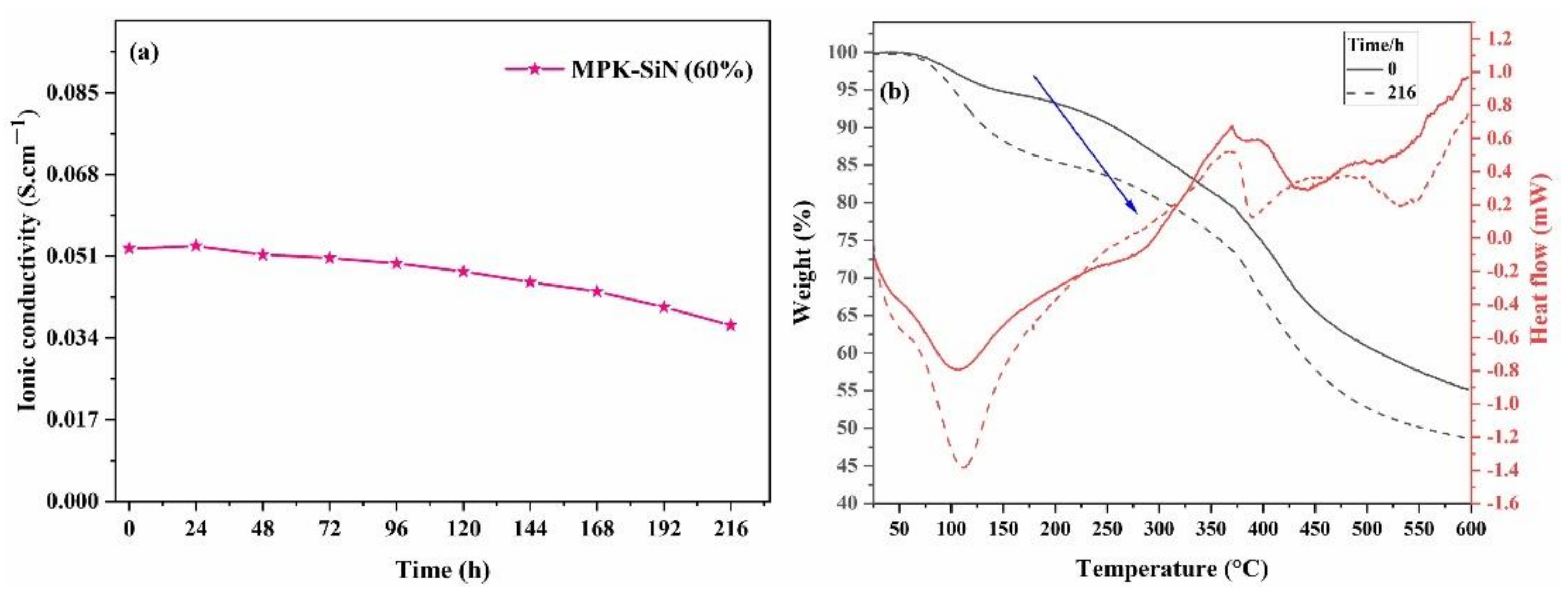
3.3. Alkaline Stability

The ionic conductivity of MPK–SiN (60%) at room temperature and the membrane’s stability in the alkaline environment were assessed after immersing the membranes in 1 M KOH aqueous solution at 80 °C for 216 h. The conductivity, attributable to OH ions, tended to decrease gradually, as shown in Figure 4a. About 70% of the original ionic conductivity was preserved after 216 h in the strongly alkaline solution.
Both the flexibility and the conductivity of the membranes were reduced after treatment in alkaline solutions at high temperatures, as emerged from the thermogravimetric analysis (Figure 4b). The membrane’s weight loss after 216 h was about 10% compared with the membrane not treated in the strong alkaline solution. Figure 5 shows the FTIR spectra of MPK-SiN (60%) before and after immersion of the membrane in KOH solution. The characteristic vibrations at 860 cm−1 and 1256 cm−1 [22] are attributable to N–H wagging and C–N bond stretching, respectively. They disappeared after the alkaline treatment, whereas the other main bands characteristic of modified polyketones remained virtually unchanged.

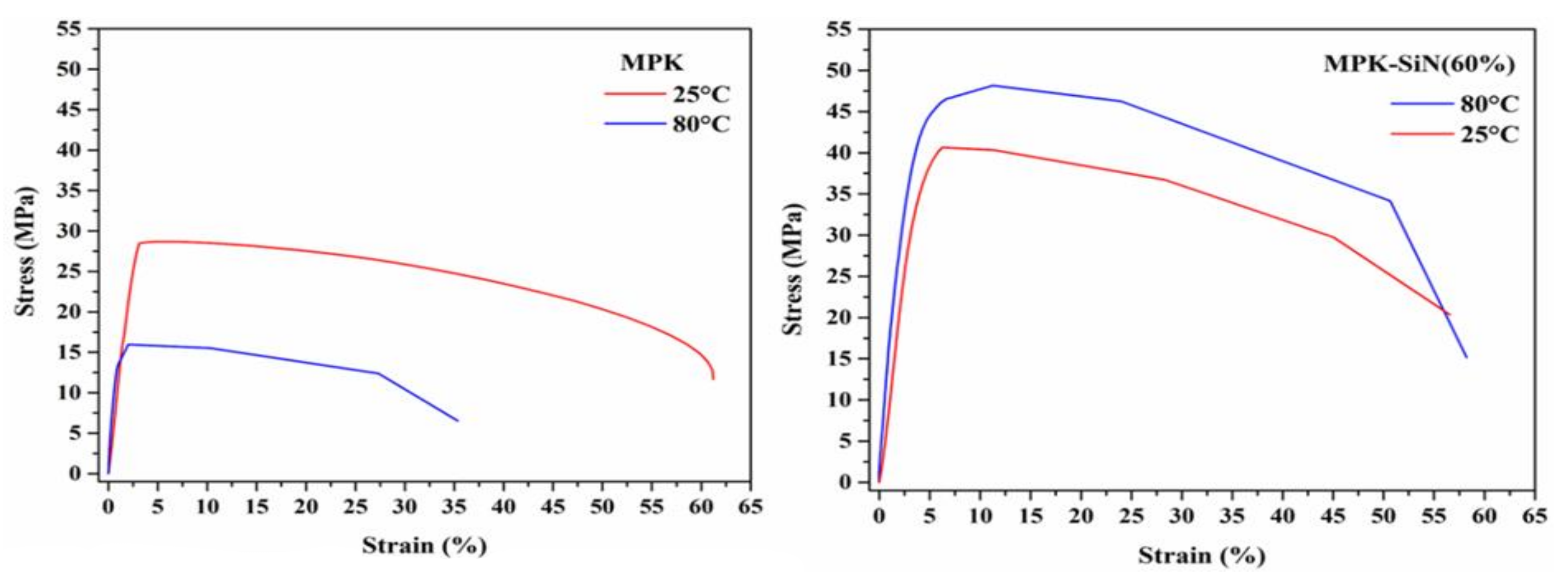
3.4. Mechanical Stability

The stress–strain curves of the membranes with and without modified silica at room temperature and at 80 °C are shown in Figure 6. In general, the membrane containing modified silica has a better mechanical performance than the modified polyketone membrane. In fact, the formation of a Si–O–Si network helps to toughen the membrane [35]. The presence of hydrogen bonding between the functional groups and modified silica also enhances the membrane’s mechanical properties [36]. At 25 °C, MPK reaches its elastic limit, corresponding to the maximum stress value of 28.5 MPa. Beyond this point, it abruptly starts the typical plastic deformation of an amorphous polymer, consisting in strain softening as a result of the localized shear band, and the consequent void formation [37]. The elastic limit decreases to 15.9 MPa at 80 °C. Adding modified silica to the membrane changes the mechanical response to elongation. The MPK–SiN membranes are tougher and more resistant than plain MPK ones: the maximum stress value increases to 40.6 at 25 °C, rising even more (to 46.5 MPa) at 80 °C. The average elongation at break (60%) was found higher than in MPK membranes. This can be explained by the increase in intermolecular forces, associated with the higher content of cationic functional groups and modified silica. It is worth noting that, unlike the curves for MPK and MPK–SiN at low temperature, which consist of elastic and softening stages, the curves for MPK–SiN at 80 °C show 4 distinct regimes. Beyond the initial elastic regime, where stress increases nearly linearly with strain, a yielding occurs, then the stress increases to the maximum value, indicating that the material is hardening, before going down upon entering the softening stage. Accordingly, there is presumably some degree of crosslinking or entanglement at 80 °C.

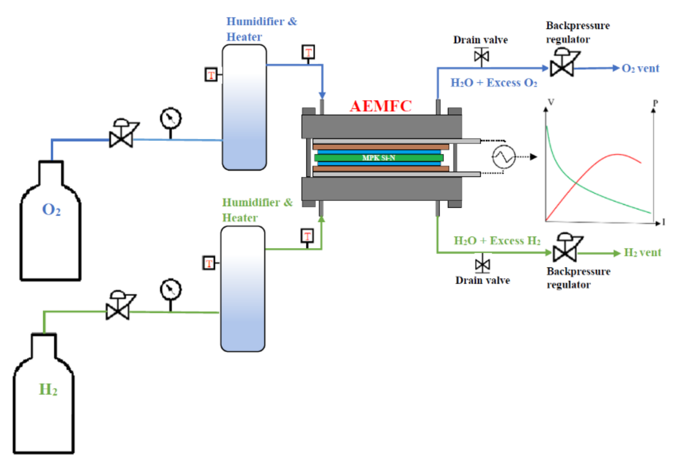
3.5. Fuel Cell Performance

Overall, the benefits of N-substituted pyrrole units in the backbone of polymer matrix and modified silica consist in an enhanced thermal and mechanical resistance, crucial to ensuring the stability of the AEM in practical applications. The performance of a selected MPK–SiN (60%) membrane in an AEMFC was demonstrated for the first time. The cell was operated at 80 °C with H2 and O2 containing moisture, and the polarization curve and power density obtained are shown in Figure 7. The open-circuit voltage (OCV) of the prepared MEAs under the present cell operating conditions was found to be 0.89 V. This value is just below the desirable value (1.1 V) for this type of fuel cell [6]. The MPK–SiN (60%) showed a peak power density of 133 mW·cm−2 at a current density of 380 mA·cm−2. This is higher than that of the membrane without modified silica (MPK), which reached a peak power density of 84 mW·cm−2 at a current density of 210 mA·cm−2. These findings suggest that incorporating Si–N improves the hydrophilicity of ion chains and enhances the OH transport in the catalyst layer of the electrode. The fuel cell with MPK–Sin (60%) consequently performed better than the one with MPK. Our results show that it nonetheless performed less well than the commercial FAA-3-50 anion exchange membrane (by Fumatech in Germany), for which the reported maximum power density was 212 mW·cm−2 at 0.54 V under the operating condition of 60 °C [38].

4. Conclusions

In this study, we demonstrate the feasibility of incorporating modified silica (Si–N) in modified polyketone to prepare membranes with improved properties, in terms of OH anion conductivity and mechanical stability, for instance. The modified silica causes a significant increase in the membrane’s conductivity (1.0 × 10⁻¹ S·cm−1 at 120 °C). The OH conductivity remains stable at around 70% of the original value under harsh conditions (after 216 h in 1M KOH solution at 80 °C). Incorporating modified silica also enhances the OH diffusion in the electrode catalyst layer and reduces the ohmic losses associated with the interfacial resistance between the membrane and the electrode. The fuel cell’s performance was assessed in a single cell tested at 80 °C: It showed a peak power density of 133 mW·cm−2 (as opposed to 84 mW·cm−2 for the membrane without modified silica). The relatively lower performance of MPK–SiN compared with other membranes described in the literature could be due to a lower alkaline stability. Overall, the performance of the MPK–SiN (60%) membranes was coupled with an excellent combination of physicochemical properties of the modified silica.

Supplementary Materials

The following supporting information can be downloaded at: https://www.mdpi.com/article/10.3390/en15051953/s1, Section S1: Modification of silica (Si-N); Section S2: Modification of polyketones (MPK); Table S1: Chemical compositions of PK (terpolymer) and amino-functionalized polyketone (MPK) samples determined by elemental analysis (CHNS); Section S3: The carbonyl conversion calculation; Figure S1: Arrhenius plots of conductivities for the MPK-SiN membranes with different amounts of modified silica (10–60%) in: (a) I form; and (b) OH form.

Author Contributions

Conceptualization, N.A. and R.D.M.; methodology, N.A., R.D.M. and E.T.; investigation, N.A., E.T. and O.C.; resources, N.A. and R.D.M.; data curation and interpretation, N.A., E.T. and O.C.; writing—original draft preparation, N.A.; writing—review and editing, N.A. and R.D.M.; supervision, R.D.M. and N.A.; funding acquisition, R.D.M. All authors have read and agreed to the published version of the manuscript.

Funding

This research received no external funding.

Data Availability Statement

The data are contained within the article.

Acknowledgments

The authors would like to acknowledge Mirco D’Incau for his help.

Conflicts of Interest

The authors have no conflict of interest to disclose.

References

  1. Communication from the Commission to the European Parliament, the Council, the European Economic and Social Committee and the Committee of the Regions a European Strategy for Data—Publications Office of the EU. Available online: https://op.europa.eu/it/publication-detail/-/publication/ac9cd214-53c6-11ea-aece-01aa75ed71a1/language-en (accessed on 6 May 2021).
  2. Sun, C.; Zhang, H. Review of the development of first-generation redox flow batteries: Iron-chromium system. ChemSusChem 2022, 15, e202101798. [Google Scholar] [CrossRef] [PubMed]
  3. Fathabadi, H. Utilizing solar and wind energy in plug-in hybrid electric vehicles. Energy Convers. Manag. 2018, 156, 317–328. [Google Scholar] [CrossRef]
  4. Gottesfeld, S.; Dekel, D.R.; Page, M.; Bae, C.; Yan, Y.; Zelenay, P.; Kim, Y.S. Anion exchange membrane fuel cells: Current status and remaining challenges. J. Power Source 2018, 375, 170–184. [Google Scholar] [CrossRef]
  5. Hagesteijn, K.F.L.; Jiang, S.; Ladewig, B.P. A review of the synthesis and characterization of anion exchange membranes. J. Mater. Sci. 2018, 53, 11131–11150. [Google Scholar] [CrossRef] [Green Version]
  6. Dekel, D.R. Review of cell performance in anion exchange membrane fuel cells. J. Power Source 2018, 375, 158–169. [Google Scholar] [CrossRef]
  7. Hren, M.; Božič, M.; Fakin, D.; Kleinschek, K.S.; Gorgieva, S. Alkaline membrane fuel cells: Anion exchange membranes and fuels. Sustain. Energy Fuels 2021, 5, 604–637. [Google Scholar] [CrossRef]
  8. Mukherjee, B.; Flor, A.; Scardi, P. Effect of oxygen adsorption and oxidation on the strain state of Pd nanocrystals. Appl. Surf. Sci. 2021, 541, 148508. [Google Scholar] [CrossRef]
  9. Osmieri, L.; Park, J.; Cullen, D.A.; Zelenay, P.; Myers, D.J.; Neyerlin, K.C. Status and challenges for the application of platinum group metal-free catalysts in proton-exchange membrane fuel cells. Curr. Opin. Electrochem. 2021, 25, 100627. [Google Scholar] [CrossRef]
  10. Varcoe, J.R.; Slade, R.C.T. Prospects for alkaline anion-exchange membranes in low temperature fuel cells. Fuel Cells 2005, 5, 187–200. [Google Scholar] [CrossRef] [Green Version]
  11. Peng, H.; Li, Q.; Hu, M.; Xiao, L.; Lu, J.; Zhuang, L. Alkaline polymer electrolyte fuel cells stably working at 80 °C. J. Power Source 2018, 390, 165–167. [Google Scholar] [CrossRef]
  12. Zhao, J.; Li, X. A review of polymer electrolyte membrane fuel cell durability for vehicular applications: Degradation modes and experimental techniques. Energy Convers. Manag. 2019, 199, 112022. [Google Scholar] [CrossRef]
  13. Ataollahi, N.; Ahmad, A.; Lee, T.K.; Abdullah, A.R.; Rahman, M.Y.A. Preparation and characterization of PVDF-MG49-NH4CF3SO3 based solid polymer electrolyte. E-Polymers 2014, 14, 115–120. [Google Scholar] [CrossRef]
  14. Hassanvand, A.; Wei, K.; Talebi, S.; Chen, G.Q.; Kentish, S.E. The role of ion exchange membranes in membrane capacitive deionisation. Membranes 2017, 7, 54. [Google Scholar] [CrossRef] [Green Version]
  15. Wu, Y.; Wu, C.; Yu, F.; Xu, T.; Fu, Y. Free-standing anion-exchange PEO-SiO2 hybrid membranes. J. Memb. Sci. 2008, 307, 28–36. [Google Scholar] [CrossRef]
  16. Li, X.; Tao, J.; Nie, G.; Wang, L.; Li, L.; Liao, S. Cross-linked multiblock copoly(arylene ether sulfone) ionomer/nano-ZrO2 composite anion exchange membranes for alkaline fuel cells. RSC Adv. 2014, 4, 41398–41410. [Google Scholar] [CrossRef]
  17. Khoon, L.T.; Fui, M.L.W.; Hassan, N.H.; Su’ait, M.S.; Vedarajan, R.; Matsumi, N.; Bin Kassim, M.; Shyuan, L.K.; Ahmad, A. In situ sol–gel preparation of ZrO2 in nano-composite polymer electrolyte of PVDF-HFP/MG49 for lithium-ion polymer battery. J. Sol-Gel Sci. Technol. 2019, 90, 665–675. [Google Scholar] [CrossRef]
  18. Nonjola, P.T.; Mathe, M.K.; Modibedi, R.M. Chemical modification of polysulfone: Composite anionic exchange membrane with TiO2 nano-particles. Int. J. Hydrogen Energy 2013, 38, 5115–5121. [Google Scholar] [CrossRef]
  19. Sun, C.; Negro, E.; Vezzù, K.; Pagot, G.; Cavinato, G.; Nale, A.; Bang, Y.H.; Di Noto, V. Hybrid inorganic-organic proton-conducting membranes based on SPEEK doped with WO3 nanoparticles for application in vanadium redox flow batteries. Electrochim. Acta 2019, 309, 311–325. [Google Scholar] [CrossRef]
  20. Gagliardi, G.G.; Ibrahim, A.; Borello, D.; El-Kharouf, A. Composite polymers development and application for polymer electrolyte membrane technologies—A review. Molecules 2020, 25, 1712. [Google Scholar] [CrossRef] [Green Version]
  21. Yun, S.; Parrondo, J.; Ramani, V. Composite anion exchange membranes based on quaternized cardo-poly(etherketone) and quaternized inorganic fillers for vanadium redox flow battery applications. Int. J. Hydrogen Energy 2016, 41, 10766–10775. [Google Scholar] [CrossRef] [Green Version]
  22. Ataollahi, N.; Cappelletto, E.; Vezzù, K.; Di Noto, V.; Cavinato, G.; Callone, E.; Dirè, S.; Scardi, P.; Di Maggio, R. Properties of anion exchange membrane based on polyamine: Effect of functionalized silica particles prepared by sol–gel method. Solid State Ionics 2018, 322, 85–92. [Google Scholar] [CrossRef]
  23. Ataollahi, N.; Vezzù, K.; Nawn, G.; Pace, G.; Cavinato, G.; Girardi, F.; Scardi, P.; Di Noto, V.; Di Maggio, R. A Polyketone-based Anion Exchange Membrane for Electrochemical Applications: Synthesis and Characterization. Electrochim. Acta 2017, 226, 148–157. [Google Scholar] [CrossRef]
  24. Zhou, Y.C.; Zhou, L.; Feng, C.P.; Wu, X.T.; Bao, R.Y.; Liu, Z.Y.; Yang, M.B.; Yang, W. Direct modification of polyketone resin for anion exchange membrane of alkaline fuel cells. J. Colloid Interface Sci. 2019, 556, 420–431. [Google Scholar] [CrossRef] [PubMed]
  25. Nawn, G.; Vezzù, K.; Cavinato, G.; Pace, G.; Bertasi, F.; Pagot, G.; Negro, E.; Di Noto, V. Opening Doors to Future Electrochemical Energy Devices: The Anion-Conducting Polyketone Polyelectrolytes. Adv. Funct. Mater. 2018, 28, 1706522. [Google Scholar] [CrossRef]
  26. Ataollahi, N.; Girardi, F.; Cappelletto, E.; Vezzù, K.; Di Noto, V.; Scardi, P.; Callone, E.; Di Maggio, R. Chemical modification and structural rearrangements of polyketone-based polymer membrane. J. Appl. Polym. Sci. 2017, 134. [Google Scholar] [CrossRef]
  27. Toncelli, C.; Pino-Pinto, J.P.; Sano, N.; Picchioni, F.; Broekhuis, A.A.; Nishide, H.; Moreno-Villoslada, I. Controlling the aggregation of 5,10,15,20-tetrakis-(4-sulfonatophenyl)-porphyrin by the use of polycations derived from polyketones bearing charged aromatic groups. Dye Pigment. 2013, 98, 51–63. [Google Scholar] [CrossRef]
  28. Araya-Hermosilla, E.A.; Carlotti, M.; Picchioni, F.; Mattoli, V.; Pucci, A. Electrically-conductive polyketone nanocomposites based on reduced graphene oxide. Polymers 2020, 12, 923. [Google Scholar] [CrossRef] [PubMed]
  29. Kang, J.J.; Li, W.Y.; Lin, Y.; Li, X.P.; Xiao, X.R.; Fang, S.B. Synthesis and ionic conductivity of a polysiloxane containing quaternary ammonium groups. Polym. Adv. Technol. 2004, 15, 61–64. [Google Scholar] [CrossRef]
  30. Tuan, C.M.; Tinh, V.D.C.; Kim, D. Anion exchange membranes prepared from quaternized polyepichlorohydrin cross-linked with 1-(3-aminopropyl)imidazole grafted poly(arylene ether ketone) for enhancement of toughness and conductivity. Membranes 2020, 10, 138. [Google Scholar] [CrossRef]
  31. Dean, J.A. Lange’s Handbook of Chemistry; McGraw-Hill: New York, NY, USA, 1999; Volume 5. [Google Scholar]
  32. Vanýsek, P. Ionic conductivity and diffusion at infinite dilution. CRC Handb. Chem. Phys. 1996, 96, 5–98. [Google Scholar]
  33. Zawodzinski, T.A.; Springer, T.E.; Davey, J.; Jestel, R.; Lopez, C.; Valerio, J.; Gottesfeld, S. A Comparative Study of Water Uptake By and Transport through Ionomeric Fuel Cell Membranes. J. Electrochem. Soc. 1993, 140, 1981–1985. [Google Scholar] [CrossRef]
  34. Xiong, Y.; Fang, J.; Zeng, Q.H.; Liu, Q.L. Preparation and characterization of cross-linked quaternized poly(vinyl alcohol) membranes for anion exchange membrane fuel cells. J. Memb. Sci. 2008, 311, 319–325. [Google Scholar] [CrossRef]
  35. Chen, J.; Shen, C.; Gao, S.; Yuan, Y.; Ren, X. Novel imidazole-grafted hybrid anion exchange membranes based on poly(2,6-dimethyl-1,4-phenylene oxide) for fuel cell applications. J. Appl. Polym. Sci. 2018, 135, 46034. [Google Scholar] [CrossRef]
  36. Gonggo, S.T.; Bundjali, B.; Hariyawati, K.; Arcana, I.M. The influence of nano-silica on properties of sulfonated polystyrene-lignosulfonate membranes as proton exchange membranes for direct methanol fuel cell application. Adv. Polym. Technol. 2018, 37, 1859–1867. [Google Scholar] [CrossRef]
  37. Miehe, C.; Göktepe, S.; Méndez Diez, J. Finite viscoplasticity of amorphous glassy polymers in the logarithmic strain space. Int. J. Solids Struct. 2009, 46, 181–202. [Google Scholar] [CrossRef] [Green Version]
  38. Son, T.Y.; Kim, T.-H.; Nam, S.Y. Crosslinked Pore-Filling Anion Exchange Membrane Using the Cylindrical Centrifugal Force for Anion Exchange Membrane Fuel Cell System. Polymers 2020, 12, 2758. [Google Scholar] [CrossRef]
Scheme 1. Schematic layout of the fuel cell measurement..
Energies 15 01953 sch001
Scheme 2. Schematics of the MPK–SiN membrane’s structure.
Energies 15 01953 sch002
Figure 1. Conductivity of MPK–SiN membranes with different weight loadings of modified silica (10–60%) in: (a) I form; (b) OH form as a function of temperature.
Energies 15 01953 g001
Figure 2. Surface morphology and backscattered (BSE) images of MPK–SiN membranes containing 10 wt% (a,b), 30 wt% (c,d), and 60 wt%, (e,f) of modified silica, respectively.
Energies 15 01953 g002
Figure 3. Temperature dependence of water uptake and swelling ratio of MPK–SiN (60%).
Energies 15 01953 g003
Figure 4. Ionic conductivity of MPK–SiN (60%) at room temperature with increasing immersion times in alkaline solution (a); TGA and DTGA profile of MPK–SiN (60%) before (0 h) and after 216 h of treatment in alkaline solution (b). The arrow indicates the weight loss.
Energies 15 01953 g004
Figure 5. FTIR spectra of MPK–SiN (60%)-B (before) and MPK–Sin (60%)-A (after) immersion in KOH 1 M at 80 °C for 216 h. (ν: stretching and ϖ: wagging vibrations of bond).
Energies 15 01953 g005
Figure 6. The stress–strain curve of modified polyketone (MPK) and MPK-SiN (60%) at 25 °C and 80 °C.
Energies 15 01953 g006
Figure 7. Polarization curve and power density of a single fuel cell with MEAs prepared using MPK and MPK–SiN (60%) membranes at 80 °C.
Energies 15 01953 g007
Table 1. Characteristics of the MPK–SiN membrane.
Conductivity (S·cm−1)
at 120 °C
Ea
(kJ.mol−1)
MembranesI FormOH FormI FormOH Form
MPK–SiN (60%)8.4 × 10−31.0 × 10−138.56.9
MPK–SiN (30%)5.1 × 10−31.8 × 10−249.516.5
MPK–SiN (10%)3.6 × 10−38.4 × 10−351.532.3
Publisher’s Note: MDPI stays neutral with regard to jurisdictional claims in published maps and institutional affiliations.

