Abstract
In the late 19th century, the three-phase induction motor was the central element of productivity increase in the second industrial revolution in Europe and the United States. Currently, it is the main load on electrical systems in global terms, reaching approximately 70% of electrical energy consumption in the industrial sector worldwide. During the 20th century, electric motors underwent intense technological innovations that enabled significant performance gains. Thus, this work analyses the performance changes in squirrel-cage rotor three-phase induction electric motors (SCIMs) with mechanical powers of 3.7 kW, 37 kW, and 150 kW and speed ranges corresponding to two poles and eight poles, connected to a low voltage at a frequency of 60 Hz and tested between 1945 and 2020. The study confirms accumulated performance gains of above 10% in some cases. Insulating materials for electrical conductors have gone through several generations (cotton, silk, and currently, varnish). Improvements to the housing for cooling, the bearings, the quality of active materials, and the design were the elements that enabled the high gains in performance. The first commercial two-pole SCIM with a shaft power of 4.4 kW was marketed in 1891, with a weight/power ratio of 86 kg/kW, and until the 2000s, this value gradually decreased, eventually reaching 4.8 kg/kW. Between 2000 and 2020, this ratio showed a reversed trend based on improvements in the performance of SCIMs. More active materials were used, causing the weight/power ratio to reach 8.6 kg/kW. The MEPS (minimum energy performance standards) of SCIMs had an essential role in the performance gain over the last three decades. Data collection was via tests at the Electrical Machines Laboratory of the Institute of Energy and Environment of the University of São Paulo. The laboratory has a history of tests on electrical equipment dating from 1911.
1. Introduction
The production of mechanical force was one of the fundamental human demands in the transformation process that took homo sapiens from an animal in nature like the others to the construction of megacities and technological mastery [1].
The process of producing mechanical force went through several phases. The domestication of animals represented an essential step in automation and the increase in labour productivity, necessary for changing the way of life from hunter and gatherer to farmer/shepherd [2]. With the use of other domesticated animals, homo sapiens could perform an activity without the need to use muscular strength directly [3].
The production of mechanical force was primarily responsible for the first two great industrial revolutions. The first industrial revolution began in England around 1750–1760, lasting until somewhere between 1820 and 1840, and was marked by the development and application of the steam engine in industrial manufacturing processes [4]. The second industrial revolution replaced steam engines or gas engines with electric motors [5].
In the late 19th century, new electric motors were more economical. They required less maintenance, took up less space, ran at a more uniform speed, and allowed a cleaner environment [6]. Within just one generation after its introduction in the 1880s, the electric motor drive had replaced steam as the preferred means of providing motive power (Figure 1) [7].
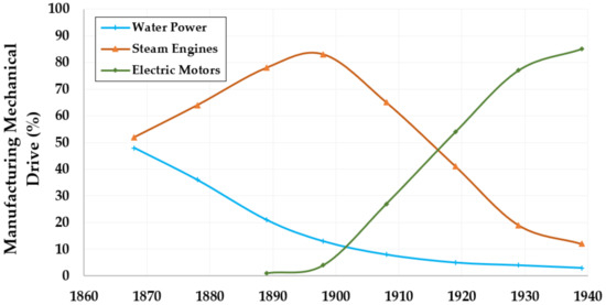
Figure 1.
Percentage of mechanical drive manufacturing from hydraulic power, steam engines, and electric motors per year. Source: adapted from [7,8].
With large-scale electric motors electrifying industrial plants, the industrial plants gained flexibility. It was no longer necessary to be close to a stream in order to use mechanical energy from water or a coal mine for direct use of coal in a steam engine [9].
The mechanical force arising from water (Figure 2a) or steam engines (Figure 2b) was generally available from a single central axis and later, when subdivided, ran the entire length of the factory, with high losses in the gears and the emission of noise and vibrations throughout the industrial plant. In some cases, the engines served different industrial buildings. The connections made by belts and gears could drive hammers, presses, looms, and other machines, transferring mechanical energy horizontally between walls and vertically through industrial floors [10]. Due to the large distances and inevitable friction in these units, 60% to 80% of the transmitted energy was lost [11]. Everything required continuous lubrication by thousands of drip lubricators, with workers having direct access to the rotating parts, thus remaining exposed to high possibilities of work accidents [12].
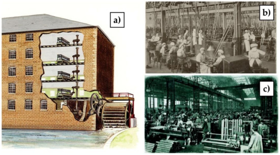
Figure 2.
An industrial organization based on: (a) mechanical drive from hydraulic energy; (b) steam engines; and (c) electric motors. Source: [13,14,15,16].
Electric motors proved to be more efficient and more economical, and they reduced reliance on the complex mechanical shaft, pulley, and belt systems to distribute the mechanical drive from the central plant throughout the plant. The drive was located close to the load, and the energy was transferred by small electrical conductors [17] (Figure 2c).
The motors could reliably be fractionally coupled to the mechanical load with the electric drive, making it possible to establish an industrial flow in the manufacturing process. By splitting the mechanical drives, flexibility in maintenance was also gained, and islands with independent operation were possible. During a breakdown, it was not necessary to stop the entire plant. This freedom revolutionized industrial design and layout and provided the possibility of optimization in process control and better working conditions, leading to significant advances in productivity [8,18,19].
Currently (21st century), electric motors are the driving force of modern industrial society. Electric motors drive domestic refrigerators, pump water for heating, and drive ventilation, enabling the distribution of compressed air and the movement of loads on conveyor belts, in addition to keeping cities’ water supplies flowing [20].
Several electric motor technologies have been developed. However, only three have become mainstream in industrial stationary electric drives. They are:
- Direct-current motors, which were the first to be developed. Their applications are limited to situations in which speed control is essential, because by controlling the voltages applied to the rotor windings (armature) and the stator windings (field), it is possible to fine-tune the speed over a wide range. However, they are expensive, have high sparking caused by switching currents, and cannot be connected directly to the electrical grid, requiring a converter. They also have a high need for maintenance compared to other technologies.
- Alternating-current synchronous motors, which are mainly reserved for high-load drives that require a constant speed. They are also expensive and require additional starting devices and electronic converters to feed the rotor winding (field) separately from the stator winding (armature). Synchronous motors are high-efficiency motors, as they have low rotor losses.
- Cage rotor induction electric motors, which since their development have been the predominant choice in residential (single-phase), commercial, and industrial (three-phase SCIMs) environments. SCIMs correspond to about 87% of the total alternating-current electric motors used in the industry [21]. Several factors make SCIMs suitable for the broadest range of applications. Some of these are highlighted in Table 1.
 Table 1. Characteristics of SCIMs.
SCIMs are seen as having undergone little change from their development to the present day, especially when compared to the obvious advances in electronics, communication, and information technologies. Hence, this research sought answers to the following questions:
- What are the most significant changes that SCIMs have undergone throughout their history?
- Has the performance of SCIMs changed since their development?
- Has the volume of SCIMs changed over time?
2. Materials and Methods
Section 3.1 is a review of the literature that shows the historical development of SCIMs, focusing on the main technological innovations, material improvements, and various projects. The sources of information are technical documents from SCIM manufacturers or scientific articles that described the processes and the main events that caused the changes in the mass/power ratio between 1890 and 1990, contributing to answering question I.
In Section 3.2, a literature review is presented discussing the variations in performance between 1935 and 2012, contributing to answering questions I and II.
In Section 3.3, the primary data collected in the Technical Test Reports of the Laboratory of Electrical Machines of the Institute of Energy and Environment (IEE) of the University of São Paulo (USP) are presented and discussed.
Between 1945 and 1996, the Technical Test Reports were only available in printed form. Thus, it was necessary to digitize the data and collect them into a spreadsheet. Between 1997 and 2020, the Technical Test Reports were already available in digital format for processing and analysis.
The Laboratory of Electrical Machines of the IEE-USP has a technical collection of approximately 21,000 technical reports. For this analysis, reports with the following characteristics were considered:
- (a)
- Three-phase induction electric motors with squirrel-cage rotor—SCIMs;
- (b)
- Technical reports of new SCIMs;
- (c)
- SCIMs tested according to current regulations, with the availability of test data at full load;
- (d)
- SCIMs in which the nameplate data were made available by the manufacturer;
- (e)
- SCIMs powered at low voltage (up to 600 volts);
- (f)
- SCIMs for power supply at the industrial frequencies of 60 Hz or 50 Hz, tested at 60 Hz;
- (g)
- SCIMs produced for continuous operation.
Using the conditions expressed in a–g, 359 technical reports of tested SCIMs with speeds corresponding to 2, 4, 6, or 8 poles, with a motor rated output power of 3.7, 37, or 150 kW, were collected for the evaluation of the change in performance between 1945 and 2020. The assessment seeks to answer the questions (I and II) that motivated this research, based on the data collected.
The results are organized into three different output power (kW) categories. The chosen groups include low power (3.7 kW), medium power (37 kW), and high power (150 kW). As the groups chosen to represent SCIMs are of significantly different dimensions, the production processes used in the manufacturing process and the standards of precision/quality of the materials are also different, even when dealing with the same equipment.
The number of poles of the electric motor determines the rotation speed, due to the arrangement and distribution of the electrical conductors of the windings located in the stator slots. In the SCIM market, historically, four speeds have been the most used. Between 80% and 90% of all the SCIMs sold have between 2 and 8 poles; therefore, this research evaluates them in this speed range. In fact, 4-pole SCIMs are dominant, representing between 45 and 70% of SCIMs [21,47].
Using the conditions expressed in a–g, 28 SCIMs with speeds corresponding to 2 poles and motor rated output powers of 3.7, and 4.4 kW were used to evaluate the change in the mass/power ratio between 2000 and 2020, seeking to answer the questions (I and III) that motivated this research, based on the data collected.
The National Institute of Metrology, Quality and Technology (INMETRO) accredits the Laboratory of Electrical Machines at IEE-USP, following ABNT NBR ISO/IEC 17025:2017 [48] under No. CRL 0011. INMETRO periodically carries out audits in accredited laboratories, aiming to guarantee the quality of the measurement results. INMETRO is a signatory to the mutual recognition agreements of the International Laboratory Accreditation Cooperation (ILAC) and the Inter-American Accreditation Cooperation (IAAC), thus following a world standard of quality and reliability.
This research, therefore, used data from standardized performance tests. This is because there may be differences between values measured in neutral laboratories and values reported by manufacturers [49], and when using the measured data, errors and uncertainties are reduced.
3. Results and Discussion
3.1. The Improvements in SCIMs
All the technological and theoretical bases for electric motor development were already advanced by the end of the 19th century. Direct-current motors were on the market, and alternating-current motors were in the full developmental stage, with research ongoing in Europe and the United States. The first patent for the electric motor with asynchronous technology was filed by the engineer Nikola Tesla [50] in 1888 and accepted in 1889 [51] in New York. The asynchronous motor became known as an induction motor, based on its working principle. However, Tesla’s proposal was similar to the current single-phase auxiliary winding motors, operating with a wound rotor. The text that explained the working principle of the new electric induction motor was published by Nikola Tesla in 1988 with the title “A new system of alternate current motors and transformers” [52].
Parallel to Nikola Tesla’s experiments in the USA were those of Galileo Ferraris in Italy. In 1885, Ferraris developed the idea that two out-of-phase currents could be used to produce two magnetic fields that could be combined to produce a rotating field, without the need for switching or moving parts, opening the door to AC electric motors [53,54,55].
The three-phase squirrel-cage rotor induction motor (SCIM) closest to the type we have today was developed by a German company AEG (Allgemeine Elektricitäts-Gesellschaft), headed by the Russian engineer Mikhail Dolivo-Dobrovolsky between 1888 and 1890 [56]. The electric motor developed by the Dobrovolsky team had very favourable characteristics such as high starting torque, more straightforward construction features, robustness in construction, and low maintenance needs. However, it also had the inconvenience of needing to be powered by a three-phase alternating-current system, which was not yet commercial. Until then, the available electrical systems were single-phase and two-phase systems. This type of supply does not provide efficient starting of the Tesla-mounted motor (starting torque practically non-existent), in addition to imposing some degree of vibration during operation. The SCIM has a high starting torque and does not need auxiliary windings and accessories such as a capacitor and a centrifugal starter, in addition to having a lower operating current compared to a single-phase motor. However, three-phase electric power generation, transmission, and distribution systems were quickly implemented with the objective of feeding the attractive SCIMs [57,58,59].
Dobrovolsky and the AEG company gained fame for the great invention. The artist Irene Ahrens created the illustration in Figure 3, which was exhibited in Berlin. The engineer appears in the sky, entering the Hall of Fame with his SCIM shown near his feet.
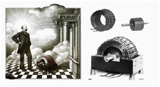
Figure 3.
Mikhail Dolivo-Dobrovolsky entering the Hall of Fame with his SCIM. Source: [57,60].
In 1891, at AEG, Dobrovolsky coordinated the first serial production of SCIMs with shaft powers between 0.4 and 7.5 kW. The first SCIMs assembled had a performance of approximately 80% for the power range produced and very high mass by today’s standards. The first commercial two-pole SCIM with a shaft power of 4.4 kW was marketed in 1891. These SCIMs had a mass/power ratio of 86 kg/kW, as shown in Figure 4.
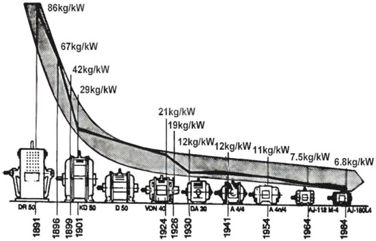
Figure 4.
Improvements in SCIM mass/power ratio between 1891 and 1984. Source: [61,62,63].
The company AEG published the famous image represented in Figure 4, which shows the mass/power ratio from the first SCIMs manufactured by the company in 1891 to the SCIMs manufactured in 1984. The optimization of materials for electrical, magnetic, and mechanical purposes, combined with solid technological innovations, made it possible to reach a ratio of 6.8 kg/kW in 1984, representing only 8% of the total mass of the two-pole SCIMs with an axle power of 4.4 kW produced in 1891, as AEG’s first commercial units.
The concept of the SCIM has not changed since the beginning of its commercialization; however, the volume has changed considerably (Figure 4).
The technological progress of SCIMs has been remarkable, stimulated by strong competition and by processes, technological innovations, and improvements in materials. According to Browning (1997) [64], the changes in the mass/power ratio resulted in better operational characteristics, even more excellent reliability, versatility, and longer life.
Browning (1997) [64] identified the following improvements in SCIMs:
- The change from open housing to closed housing;
- The change from plain bearings to anti-friction bearings. (In 1945, 35–40% of SCIMs used plain bearings);
- The change from cotton-insulated wires to varnished wires in the stator windings;
- Construction of the squirrel-cage rotor using copper or cast aluminium bars.
The adoption of industry standards has played a significant role in the progress of SCIMs [28,64]. An example is the thermal classification of insulating materials, which first appeared in 1898. In 1911, standardization by the AIEE Standards (now IEEE—Institute of Electrical and Electronics Engineers) established temperature limits for SCIMs. The 1915 edition of the AIEE Standards included definitions of insulation classes A, B, and C and the materials assigned to those classes. In 1929, the first SCIMs built to NEMA standards were made available on the market, setting standard dimensions and operating characteristics for specific ratings for the first time. Users were given the ability to directly replace SCIMs via the concept of stock electric motors for quick replacement in case of failure [64].
It is possible to observe in Figure 5 the tremendous technological innovations that were decisive in reducing the mass and volume of SCIMs.
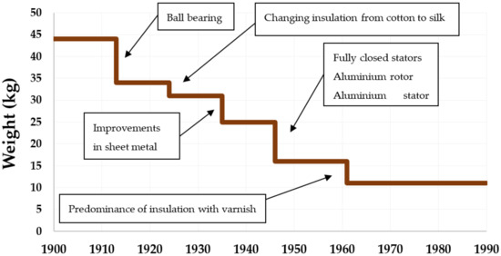
Figure 5.
Chronology of 0.75 kW SCIM mass reduction between 1900 and 1990. Source: [65,66,67,68].
At the beginning of the 20th century, the first major technological innovation was the development of ball bearings, replacing the traditional plain bearings that were bulky, heavy, and required lubrication with oil. With the new bearings and the reduction in friction losses, the mass and volume of the SCIMs decreased considerably.
Between 1913 and 1940, there were gains in the quality of materials, improving compaction and making it possible to reduce the volume of copper and iron used in SCIMs and to reduce losses. In the 1940s, rotors previously built using iron sheets began to be developed using cast aluminium, adding more mass reduction, as shown in Figure 5. In addition, in the 1940s, with successive advances in metallurgy, SCIM housings could be built in an increasingly closed way and could maintain the cooling of the windings located in the stator.
In the early 1960s, a series of advances in insulation systems were instrumental in reducing the volume of SCIMs. Between 1960 and 1970, SCIMs went through five generations of materials used to construct insulation for electrical conductors. In the first SCIMs, the insulation was composed of paper, and later cotton. Then, insulation with varnish predominated until the present day. Figure 6 shows in white the area necessary to accommodate electrical conductors of the same metallic volume inside the stator magnetic package slot for different insulation technologies [63].
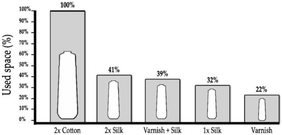
Figure 6.
Space used by different insulation technologies for the same SCIM output power. Source: adapted from [63].
The first significant innovation in SCIM insulation systems was the replacement of the double layers of cotton between the conductors and the sheets with two layers of silk, allowing a reduction of approximately 59% of the groove area in the metal sheets (ferromagnetic material) of the stator. The second major innovation was the introduction of varnish used in conjunction with silk, giving an area reduction of over 2%, as shown in Figure 6. Subsequently, improvements in the quality of silk and varnish allowed an area equivalent to be reached of only 22% of the space required for the same electrical conductor using cotton as an insulator.
Successive technological innovations and improvements in electrical, magnetic, and mechanical materials achieved significant volume compaction in SCIMs between 1903 and 1974 [28], as illustrated in Figure 7a. Figure 7b shows the changes in appearance and frame dimensions of SCIMs of different powers from the open construction of 1904 to those used in the 1970s, similar to today’s drip-proof and fully fan-cooled SCIMs.
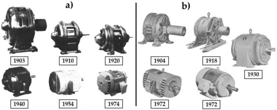
Figure 7.
Dimension trends and housing changes of 11 kW 4-pole SCIMs between 1903 and 1974. (a,b): the changes in appearance and frame dimensions of SCIMs of different powers from the open construction of 1904 to those used in the 1970s. Source adapted from: [28,53].
Figure 7a presents SCIMs designed for operation at 220 volts and 11 kW, built by General Electric (GE). In Figure 7a, it is possible to observe the changes in the NEMA 404 housing over the years, and two significant innovations are evident in the images of SCIMs between the years 1920 and 1954: axial extension of the rotor at the rear and the closed housing, seen from 1954 and made possible by the improvement in insulation systems, enabling the transfer of heat from the windings to the outside.
Figure 7b shows a small SCIM (1904) built without a fan and considered to be “self-ventilated” by the semi-open housing. As early as 1918, SCIMs used a fan attached to the shaft for cooling. In 1930, the 15 kW SCIM already had a more efficient fan and could adopt a more closed design. In 1972, the engines were already drip-proof. Figure 7b shows 18.5 kW and 45 kW SCIMs. They could be fully enclosed (45 kW), allowing a reduction in SCIM dimensions. As a result of the improved insulation between the conductors and between the conductors and the ferromagnetic material of the sheets, the temperature of the winding wires and the groove walls became more homogeneous, as they were closer together with a thinner insulating layer. The temperature of the set decreased, and for this reason it was possible to increase the power considerably for the same housing. The stator slot was significantly reduced for the same power, and the magnetic section between the slots could be increased. There was also an improvement in the ferromagnetic material, an increase in the magnetic flux, and a consequent decrease in the number of turns per stator coil for the same electrical voltage.
According to Alger and Arnold (1979) [28], to avoid hot spots in the centres of long cores, radial ducts were introduced in the stator and impellers in the rotor operating as fans, creating the airflow through the stator channels. Therefore, the rating given to the NEMA 404 frame with an axle height and length of 25.4 cm and 31.1 cm, respectively, was increased with respect to mechanical power from 5.5 kW in 1897 to 75 kW in 1974, as shown in Table 2.
Table 2.
Mechanical power increments in the same frame from 1898 to 1974. Source: [28].
The reduction in the volume of SCIMs also made it possible to reduce their costs, intensifying the electrification of industrial plants. For example, in 1890, a 3.7 kW SCIM weighed approximately 450 kg and cost about USD 900, and in 1957, a SCIM of the same power weighed around 50 kg and cost USD 110 [64]. Thus, the relationship between value and mass remained practically the same. However, as mass reduced significantly, the price of the SCIM reduced considerably, since the cost of an SCIM is fundamentally a function of the quantity and quality of materials used.
The company Hitachi produced three SCIMs of 3.7 kW in 1910, and in 2010 the total production was already 40 million SCIMs. The company recorded the significant advances that SCIMs have made over more than 100 years in this period. Hitachi divides advances in electric motors into three distinct periods. Between 1830 and 1890 is the period of inventions, from 1930 to approximately 1950 is the period of scientific initiatives, and between the 1950s and the present day is the period of industrial initiatives [69].
Various technical and technological developments have made Hitachi SCIMs smaller and lighter over the 100 years from 1910 to 2010. Figure 8 presents the leading technologies used by Hitachi that made it possible to reduce the mass of the first SCIM, with a power of 3.7 kW (four poles) manufactured by the company in 1910 with a mass of 150 kg, to approximately 20% of the mass in 2010 (30 kg).
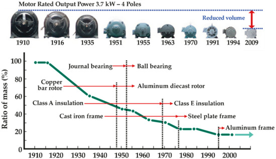
Figure 8.
Hitachi SCIM mass changes for 3.7 kW (4 poles) SCIMs. Adapted from [69].
The main changes recorded were the use of aluminium in the rotor in the late 1940s. Later, in the 1950s, bearings improved, moving from sliding technology to ball bearings. In the late 1960s, improvements were made with the application of new insulation classes of varnishes on the wires. In the mid-1970s, cast iron frames gave way to lighter sheet steel frames. In the 1990s, aluminium structures closed the cycle of major technological innovations in Hitachi’s first 100 years (1910–2010).
Reduction of Volume and Losses of Ferromagnetic Materials in SCIMs
The first electrical devices to use ferromagnetic materials were developed in the second half of the 19th century. Knowledge about these materials, such as their structure, was absent; as a result, the development of the projects was based on trial and error [70].
For SCIMs to thrive, they needed to advance in generating, transmitting, and distributing electrical energy via alternating current (AC) [71]. Charles Proteus Steinmetz was hired by General Electric (GE) (by Thomas Alva Edison) to improve the AC distribution system. He developed the complex representation of variables sinusoidally in time, which is still in use today [72]. Steinmetz deepened his studies of ferromagnetic materials to better compete with Westinghouse, which manufactured the induction motors invented by Tesla.
The first concepts regarding losses in ferromagnetic materials, traditionally known as iron losses, were developed by Steinmetz [73]. Via understanding how the losses behaved with changes in the intensity of the magnetic field, the General Electric induction motors became competitive, due to the reduction in the volume of material used [74].
Steinmetz’s secret was to use increasingly thin sheets. The eddy current losses depend on the square of the sheet thickness, the hysteresis losses, and the square of the magnetic field strength [75]. Steinmetz’s discoveries led to more efficient rolling mills that produced thinner and thinner sheets.
Understanding the ferromagnetic losses (hysteresis and eddy current) was decisive for selecting increasingly thin sheets to assemble the stator and rotor magnetic package. Thus, it was possible to impose a greater magnetic flux density in the package of sheets, approaching the limit of the magnetic saturation of the plate. This knowledge contributed to reducing the volume of SCIMs to approximately one third of the initial volume between 1891 and 1901 (Figure 4).
Subsequently, the development of ferromagnetic materials focused on reducing iron losses through heat treatment of the materials and the “doping” of silicon to increase the resistivity of the composite [76], thus enabling the intensification of the magnetic field and consequently reducing the volume of the SCIMs for a defined power.
To better understand the reason for the volume reduction of SCIMs over time, as shown in Figure 4, regarding the reduction provided by the improvement in ferromagnetic materials, it is possible to model the volume of SCIMs from the increase in the intensity of the magnetic field in their structures. This imposition of increasingly intense magnetic fields was one of the main reasons for the reduction in the volume of electric motors since their development.
A mathematical expression that translates the volume/power ratio as a function of the imposed magnetic flux density can be deduced from the electromechanical energy conversion equation, where the phase-induced electromotive force is given by Cardoso et al. [70]:
where is the frequency (Hz), is the number of adequate turns in series per phase, and is the magnetic flux per pole (Wb).
Furthermore:
where is the density of the magnetic flux in the air gap (T), is the packet length (m), is the radius of the air gap (m), and is the number of pole pairs.
The electric current expressed as a function of the magnetic field in the motor air gap was expanded from the classical magnetomotive force equation FMM = NI = ℜϕ, and can be expressed as [70]:
where is the magnetic air permeability (H/m), is the number of pole pairs, and is the thickness of the air gap (m).
Ignoring any type of losses, the motor power will be given by , where is the number of motor phases.
Substituting and by their values expressed in Equations (1) and (3) results in:
where represents the synchronous motor rotation in rps and represents the motor volume.
Reorganizing Equation (4), it is possible to mathematically verify the volume/power ratio of SCIMs and other equipment that uses ferromagnetic materials, in proportion to the intensity of the internal magnetic field in Equation (5).
with:
Equation (5) is inversely proportional to the magnetic flux density characteristic square, expressing a curve similar to that of Figure 4. It suggests that one of the primary explanations for the reduction in the volume (or mass) of SCIMs over the years was the more significant imposition of the magnetic field on its magnetic structure, as shown in Figure 9.
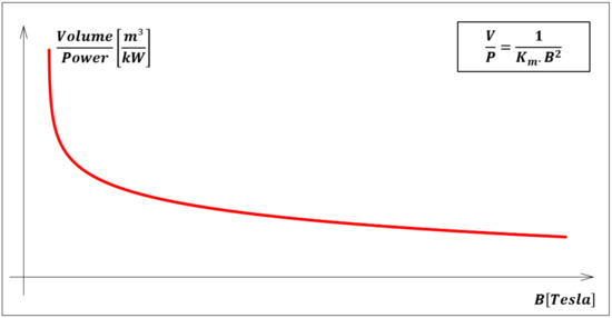
Figure 9.
Density of the magnetic flux in the air gap and the volume of SCIMs.
Figure 9 represents the relationship between the improvement in the quality of the ferromagnetic material and the reduction in SCIM volume, considering the same output power. As a result of Equation (5), the curve is theoretical since it is impossible to design an electric machine with unlimited magnetic flux density (B) or a value of B very close to zero. Hence, the curve represents one of the essential reasons for the reduction in the volume of SCIMs from the first units to the present day.
It is estimated that for 110 kW electric motors, the losses in ferromagnetic materials represent, on average, 59% of the total losses [77]. The losses increase with increasing frequency of the electric voltage. These materials have also undergone improvements from the first electric motors to the current ones.
Since Michael Faraday demonstrated electromagnetic induction in 1831 [78], soft magnetic (ferromagnetic) materials have continued to evolve. When iron was the only soft magnetic material available, metallurgists and materials scientists experimented by introducing other elements to improve the efficiency of iron.
The main known losses in ferromagnetic materials are hysteresis and eddy current losses. Hysteresis losses occur through the coercivity of a magnetic material. Each time a material with magnetic characteristics completes an entire cycle of its magnetization curve, the area within this curve measures the energy lost in the magnetization process.
The second primary loss mechanism in soft magnetic materials is eddy currents. Eddy currents are closed electric current paths generated in a conductor whose source is a time-varying magnetic field. These current loops create a magnetic field in opposition to the change in magnetic flux (according to Faraday’s law of induction). The energy losses caused by eddy currents scale approximately with the square of the operating frequency and are thus a significant cause of losses in alternating-current machines.
The development of silicon (electrical) steel in about 1900 was a notable event in the advances of soft magnetic materials [79]. Silicon steel still dominates the global soft magnet market and is the material of choice for large-scale transformers and electrical machines such as SCIMs. In 1900, Robert Hadfield, a metallurgist from England, and his team developed unoriented silicon steel by adding up to 3% of silicon to iron and increasing its electrical resistivity (ρ) [80].
The team led by the American metallurgist Norman Goss developed grain-oriented silicon steel in 1933, promoting grain growth along a crystalline direction. The most common applications for silicon steel are large-scale transformers (grain-oriented silicon steel) and electrical machines (unoriented isotropic silicon steel is preferred for rotating machines), for which the economical price is a great benefit [80].
Improvements in magnetic properties were also achieved, from the treatment of iron to minimize chemical impurities to the techniques of slicing the iron into thin sheets. Subsequently, silicon was used to increase the electrical resistance of iron and control the crystal orientation. Figure 10 presents the reduction in losses in the core of electrical machines in watts for each kilogram of ferromagnetic material, highlighting the predominant technological advances of each period.
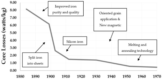
Figure 10.
Changes in losses in the core of electrical machines (ferromagnetic material). Source: adapted from [7,76,81].
It is possible to observe in Figure 10 that between 1884 and 1970, the losses in the core of alternating-current electrical equipment reduced from 8.16 W/kg to 0.44 W/kg, which represents an approximately 95% reduction.
Figure 10 shows low frequencies (50 or 60 Hz) and a constant B (T) value, as both directly influence losses in ferromagnetic materials.
Today’s primary soft ferromagnetic materials in electric motors are iron and ferrosilicon alloys (2022). However, materials with lower eddy current and hysteresis losses have been developed since the 1970s.
After the energy crisis of the 1970s, the first attempts to use amorphous materials for electric motors were recorded (1981). Mischler et al., demonstrated the low-loss potential of the amorphous stator in a laboratory environment [82].
In 1967, a new class of materials, amorphous alloys, was introduced [83]. In the mid-1970s, interest in amorphous alloys based on iron and cobalt increased, and these materials began to find applications [84]. However, only in 1988 did Hitachi researchers investigate Nb and Cu additives. They added an annealing step to amorphous alloys to produce small-spaced crystallites of iron or cobalt within an amorphous matrix material. The formation of isolated crystallites of transition metals reduced the eddy current losses of these materials compared to traditional amorphous alloys. Despite a higher initial cost than silicon steel, these advanced alloys can reduce the total lifetime costs of electric motors due to reduced losses.
Currently (2022), unique treatments involving thermal manipulation, laser bombardment, and other technologies continue to produce high-performance magnetic materials.
3.2. Changes in the Performance of SCIMS
It was not just the masses and volumes that changed. Successive changes in the performance of SCIMs occurred from the first commercially available versions to the mass manufacturing versions of today (2022).
Several technological advances explained the changes in the performance of SCIMs, from the technological innovations already mentioned to improvements in production processes and the purification of active materials. Sven Sjöberg [66] presented the reasons for the performance gains of SCIMs manufactured by the company ABB Motors after the great cycle of innovations that closed in the 1970s:
- (a)
- Cutting tooling: improving mechanical precision and enabling the elimination of burrs;
- (b)
- Laminated package: lamination mixing, lamination control before pressing, welding, or stator clasping. Quality assessment of raw material sampling before casting (rotor);
- (c)
- Machining the outer surface of the stator core (generally not necessary): reduces surface roughness and improves tolerances;
- (d)
- Stator winding: length of coils, type of winding, filling factor, insulation system, loops, and connections;
- (e)
- Impregnation: good filling results and improvements in thermal exchanges;
- (f)
- The casting of the rotor cage: filling of the slots and the closing rings of the cage, purity of the casting material, and balancing of the rotor;
- (g)
- Alignment of the rotor shaft and machining of the outer surface of the rotor.
Sven Sjöberg (1997) presented the performance changes to SCIMs manufactured by ABB Motors between 1935 and 1996, as shown in Figure 11. According to Sven Sjöberg, performance changes did not result from any performance regulation but occurred due to materials improvements, technological innovations, and improvements in production processes [66].
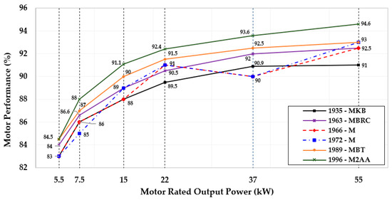
Figure 11.
Changes to performance of 4-pole SCIMs between 1935 and 1996. Source: adapted from [65,66].
It is observable in Figure 10 that in the 1960s and 1970s there was a reduction in the average performance of SCIMs, considering a wide range of power. In some periods, the performances were inferior to those obtained by the industry in 1935. The researcher Sven Sjöberg, in his text, does not identify the elements that led to this temporary drop in performance between the 1970s and 1980s.
For the United States Department of Energy (DOE), the 1960s and 1970s were periods of global economic crisis, where SCIM manufacturers built lower-cost equipment compared to previous years. These SCIMs were less efficient, as shown in Figure 12, as they minimized the use of materials such as copper, aluminium, and steel. According to the DOE, these SCIMs had lower initial costs than previous projects. However, they consumed more electrical energy due to their inefficiency, so their use throughout the life cycle was more expensive [85].
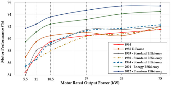
Figure 12.
Changes to performance of 4-pole SCIMs between 1944 and 2012. Source: adapted from [85].
Figure 12 shows that the four-pole SCIMs manufactured and marketed in North America in the 1980s had even lower performance than SCIMs manufactured in 1944, which were the first officially registered by the DOE.
According to the DOE, less-efficient and more-compact SCIMs became possible with insulating materials that could withstand high temperatures. These SCIMs were designed to admit higher losses due to the increase in temperature in the coils located in the stator, making it possible to accommodate the winding wires in smaller frames without damaging the insulation [85].
Figure 13 shows the performance changes to four-pole SCIMs with motor rated output powers of 37 and 45 kW, operating at 50 or 60 Hz, at low voltage.
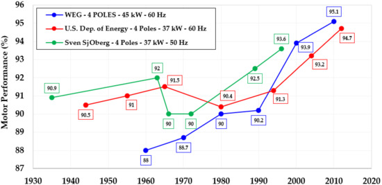
Figure 13.
Changes to performance of 4-pole SCIM performance between 1935 and 2012. Source: adapted from [65,66,85].
Figure 13 shows the average performance presented by Sjöberg and the DOE. The SCIMs showed a performance reduction between the 1960s and 1980s, and only the data provided by WEG (2015) showed a continuous increase in performance. Figure 13 illustrates the performance data available in the company’s publications, beginning in 1960, which was the year the company was established. The data show performances below those obtained in the international market, with high performances recorded for 2010.
3.3. Changes in the Performance of SCIMs between 1945 and 2020
SCIMs and most of the electromechanical equipment developed in the 20th century underwent a series of improvements and refinements, from conception through the technological advances in construction processes, mainly in the improvement in the quality of the materials used.
Test results based on data from 1945 and 2020 were used to analyse the change in the performance of 359 SCIMs, with speeds corresponding to two, four, six, or eight poles, at a motor rated output power of 3.7, 37, 150 kW, in order to aid in answering the questions (I and II) that motivated this research.
Figure 14 shows the trends in performance of two-pole SCIMs over time, tested from 1945 to 2020.
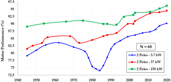
Figure 14.
The average performance of 2-pole SCIMs between 1945 and 2020.
Figure 14 shows test results from 68 SCIMs organized into three output power categories and arranged over time. In the years in which results were obtained from more than one SCIM of the same speed and mechanical power, the average performance was calculated for the construction of the figure. In addition, in the years in which there were no SCIMs tested at the output power used in the analysis, the linear regression method was used between the adjacent years in which data were available, in order to construct the figure. The same considerations were applied to Figure 15 (four-pole SCIMs), Figure 16 (six-pole SCIMs), and Figure 17 (eight-pole SCIMs).
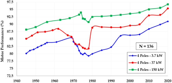
Figure 15.
The average performance of 4-pole SCIMs between 1945 and 2020.
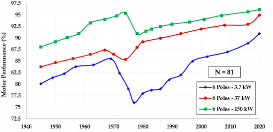
Figure 16.
The average performance of 6-pole SCIMs between 1945 and 2020.
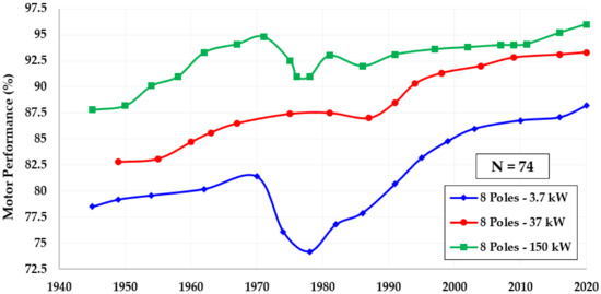
Figure 17.
The average performance of 8-pole SCIMs between 1945 and 2020.
Table 3 presents the cumulative performance gain between 1945 and 2020 for the three analysed power values.
Table 3.
The average performance of 2-pole SCIMs between 1945 and 2020.
Generally, high-power SCIMs are always associated with high performances. They are often subjected to more rigorous quality control routines by the manufacturers and users, who are concerned about the losses in this equipment because they are primarily the predominant industrial electrical loads. This fact results in SCIMs of higher power such as 150 kW having smaller performance gains over that time interval. Medium-power (37 kW) and low-power (3.7 kW) SCIMs are associated with high performance gains, with accumulated values of 13% and 11.1%, respectively, based on the analysed period. In other words, the reduction in losses in two-pole SCIMs between 1945 and 2020 was 53.1% for 3.7 kW, 70.3% for 37 kW, and 65.1% for 150 kW. The trends shown in Figure 14 and Table 3 for two-pole SCIMs are similar to those in Figure 15 and Table 4 for four-pole SCIMs, in Figure 16 and Table 5 for six-pole SCIMs, and in Figure 17 and Table 6 for eight-pole SCIMs.
Table 4.
The average performance of 4-pole SCIMs between 1945 and 2020.
Table 5.
The average performance of 6-pole SCIMs between 1945 and 2020.
Table 6.
The average performance of 8-pole SCIMs between 1945 and 2020.
According to Table 4, the loss reduction for four-pole SCIMs was 54.8% for 3.7 kW power, 69.1% for 37 kW, and 72.9% for 150 kW between 1945 and 2020.
According to Table 5, the loss reduction for six-pole SCIMs was 54.8% for 3.7 kW power, 69.1% for 37 kW, and 68.1% for 150 kW between 1945 and 2020.
According to Table 6, the loss reduction for eight-pole SCIMs was 45.1% for 3.7 kW power, 65.1% for 37 kW, and 67.2% for 150 kW between 1945 and 2020.
The three curves (3.7 kW, 37 kW, and 150 kW) showed similar trends in the four figures presented (Figure 14, Figure 15, Figure 16 and Figure 17), making it possible to separate three periods:
- Between 1945 and the mid-1960s, SCIMs presented a curve indicating continuous increasing performance gains;
- Between the 1960s and 1980s, SCIMs showed significant performance drops, in some cases reaching lower levels than the SCIMs marketed in 1945;
- Between the 1980s and 2020, performance improvement dominated the scenario. It resulted in high levels of performance in the last years of the analysis, presenting a net result, from 1945 to 2020, of gains above 10% in average performance, corresponding to a worst-case reduction of losses of approximately 45%.
Several elements influenced these trends for each of the three periods described above. At first, between 1945 and the mid-1960s, an intensive process of technological innovation was identified, highlighting the following elements that directly influenced the performance gains of SCIMs:
- Many SCIMs tested in the 1940s still had plain bearings. Sleeve bearings, compared to ball bearings, produce more noise, are larger and heavier, and generally provide greater friction, requiring oil lubrication;
- In the 1940s, there was a transition from rotors made of iron bars to rotors made of cast aluminium bars. Aluminium has lower electrical resistivity and lower density, and is therefore lighter for the same power;
- Advances in metallurgy allowed SCIM housings to be built more compactly, improving the safety of operation and maintenance workers, maintaining winding ventilation, and reducing masses and volumes;
- The insulation system in that period underwent substantial advances, moving from the use of cotton as an insulator to silk, where a significant reduction in the size of the grooves was possible, reducing the size and volume of the SCIMs;
- Due to the use of silk, it was also possible to insert more copper into the same slot, reducing the most significant losses in SCIMs (Joule losses in the stator winding wires);
- Improvements in the manufacturing processes of SCIMs were remarkable in that period, whether due to advances in cutting tools or better machining of the active ferromagnetic materials of SCIMs;
- Between 1884 and 1970, the core losses of AC SCIMS dropped from 8.16 watts/kg to 0.44 watts/kg, which represents an approximately 95% reduction.
In the second period, between the 1960s and 1980s, SCIMs showed significant drops in performance, making it possible to identify the influence of the following elements. In this period, insulation from varnish was developed. The varnish made it possible to withstand high temperatures without compromising the insulation. For this reason, SCIM designs emerged that admitted more significant losses in the stator winding wires due to increased temperature in the coils. Temperatures up to 180 °C, already standardized in the 1970s (Table 7), were observable in some SCIMs.
Table 7.
Thermal class of insulation of electrical conductors. Source: [86].
Cotton and silk operated only as electrical insulators. In contrast, the varnish used, in addition to being an electrical insulator, is a thermal conductor. This factor made it possible to accommodate the winding wires in even more miniature housings without damaging the insulation and to improve cooling with an increased transfer of heat produced mainly in the stator winding wires to the external surface, via the design of the fins on the housing.
When varnish is used to insulate the winding wire, it conducts the temperature rise resulting from the losses in the stator winding wires to the housing (Figure 18). In the process, the fins are designed to increase the contact area with air, thus improving the heat dissipation process and changing the geometry of the SCIM housing.
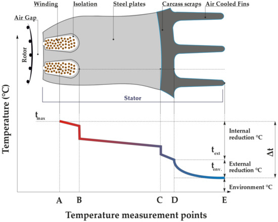
Figure 18.
Stator temperature measurement points (A, B, C, D and E). Adapted from [87].
The temperature reduction in SCIMs between points A and E, expressed in Figure 18, can be described as follows:
A—the hottest point of the SCIM, inside the slot that generates the heat from the Joule losses of the stator winding wires;
AB—the temperature reduction resulting from heat transfer from the hottest point to the outer wires of the coil. As air is not a good conductor of heat, there must be no “voids” inside the groove. Therefore, the windings must be compacted and impregnated with varnish, filling the voids as much as possible;
B—the temperature reduction caused by the insulator inserted between the winding wires and the metal plates. It is common to use special paper or synthetic insulating foil to line the groove;
BC—the temperature reduction by thermal conduction in the SCIM core plates;
C—the temperature reduction in the contact between the core and the housing. Precision machining of the housing to reduce surface irregularities is essential in heat conduction;
CD—the temperature reduction by thermal conduction through the shell thickness;
DE—the temperature reduction due to the increase in the SCIM surface exposure caused by the fins.
The reduction in copper mass meant that SCIM manufacturers were able to reduce the final cost of the equipment, since copper is the highest cost input in the construction of SCIMs. This trend was verified in the test reports of the analysed period. An increase in Joule losses (I²R) in the stator winding wires was mainly observed in relation to previous decades. When the section of the copper conductors reduces, the total mass of the SCIM also reduces. The reduction in copper increased the Joule losses and consequently increased the operating temperature of the SCIMs. The heat generated internally could be more easily dissipated in the housing with varnish.
In the third period, between the 1980s and 2020, improvements in the average performance of SCIMs were evidenced mainly by the following observations.
Minimum performance level policies were applied in the world’s largest economies between the 1990s and 2020. The policies that indicate the minimum energy performance of equipment are entitled “minimum energy performance standards (MEPS),” which specify minimum levels of energy performance for commercial purposes. The main objective of MEPS is to guide the performance of the equipment for the consumer and establish a minimum legal requirement for commercialization.
Government bodies usually institute MEPS policies. In the case of SCIMs, MEPS are divided into performance classes, allowing different levels that increase the requirement of a specific minimum performance value according to technological advances and market acceptance. Performance classes for SCIMs internationally are harmonized with the IE code in IEC 60034-30-1 [88], which is widely accepted as the global standard, making performance classes comparable across the various regional energy policy documents for SCIMs. The standard defines efficiency classes from IE1 to IE4 (Figure 19), where IE1 is the lowest, and IE4 is the highest. Similarly, in the United States, performance classes IE1 to IE4 are called Standard, High efficiency, Premium efficiency and Super-Premium efficiency, according to NEMA [89]. The new IE5 class has not been defined in detail; however, it is foreseeable in a future edition of the standard. For IE5 SCIMs, the goal is to reduce losses by about 20% compared to the IE4 class [88,90].
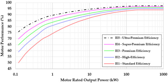
Figure 19.
Efficiency levels in the IEC 60034-30-1 (2014) classification standard curves for 50 Hz, 4-pole SCIMs. Source: [88,90].
The SCIMs tested in 2020 were already IE3. Therefore, in the next few years, it should be possible to make another short jump in the performance gain of SCIMs.
The implementation of MEPS for SCIMs took place in the USA and Canada in 1997 and was later gradually applied in other countries, with modifications implemented by each energy agency of the various countries, but maintaining the harmonization as shown in Figure 20.
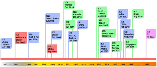
Figure 20.
Timeline of global minimum performance standards for SCIMs. Source: [91,92,93,94,95,96,97].
To comply with the new legislation, which imposes higher performance indices, the central intervention of the manufacturers, verified in the test reports of the analysed period, was the reduction of Joule losses in the stator, because stator windings started to be built with more copper mass compared to previous decades. This movement also meant that the mass of SCIMs, which until then had decreased with time, began to increase, returning to the levels verified in the 1960s.
During this period, other secondary elements were observed that also influenced the improvement of the performance of SCIMs:
1. Advances in the design of SCIMs through the use of modelling software, enabling structural improvements in the coupling and a reduction in vibrations and noise;
2. Three-dimensional computational modelling of electromagnetic fields, enabling project optimization;
3. Advances in the processes of the casting of steel-silicon sheets;
4. Use of more efficient cooling systems (ventilation).
The three periods described led to profound changes in the mass/power ratio of SCIMs. The analysis presented in Figure 4 demonstrates the falling mass/power ratio and points to the lower levels in the following years needing to be updated. For this reason, Figure 21 was created to answer question III, which was one of the questions motivating this research.
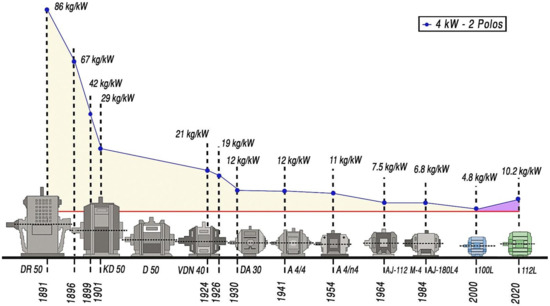
Figure 21.
Changes to SCIMs in the mass/power ratio between 1891 and 2020.
The research relied on SCIM test data from 1945 to 2020. However, SCIM mass data was only available in technical reports from 1997 onwards. Before this date, few reports presented a record of the mass of the SCIM under test. Between 1945 and 2020, records of seven SCIMs with power and speeds compatible with Figure 4 and with mass records were discovered. The mass/power ratio found in these seven SCIMs was compatible with the data published by AEG. Thus, Figure 4, containing results between 1891 and 1984, was updated with data obtained in this research (Figure 21).
To create Figure 21, in 2000, 12 two-pole SCIMs with power between 3.7 kW and 4.4 kW were used, and in 2020, 16 SCIMs were used in the same power range and for the same speed. After calculating the mass/power ratio for each SCIM, the arithmetic mean was calculated for each of the two years under analysis.
A significant result verified in Figure 21 was the increase in the mass of SCIMs from the 2000s onwards, reaching the level of 10.2 kg/kW for the same power and speed, returning to levels verified in the 1950s.
The increase in mass was produced mainly by using conductors of a larger section, to reduce the block where the most significant losses in SCIMs are found, that is, the losses from the Joule effect in the wires of the stator windings.
The reduction in volume of an electrical machine can also result in challenges in keeping components cool. In the case of high heating, deterioration of the properties of most materials (such as insulators, coils, and sheets of ferromagnetic material) can occur, causing a reduction in the useful life of the equipment. This is one of the reasons that justify the average increase in the carcass of SCIMs in the last two decades.
There was also an increase in the lengthening of the rotor package, and consequently of the stator windings, significantly increasing the amount of material used in the construction of the high-efficiency motor, as seen in Figure 22.
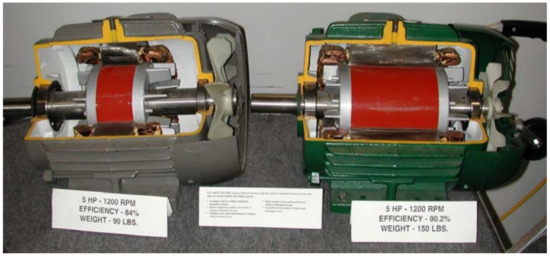
Figure 22.
The difference in the material quantity between Standard SCIM and High-Efficiency SCIM. Source: [98].
In Figure 22, the most significant change made to increase the performance of a 5 HP (3.7 kW) electric motor from 84% to 90.2% was an increase in mass of 27 kg or approximately 33%, while maintaining the same carcass.
For performance gains superior to those shown in Figure 22, increasing the carcass to accommodate the new stator and rotor dimensions was necessary. Figure 21 shows that SCIMs went from a 100L housing in 2000 to a 112L housing twenty years later (2020).
The mass/power ratio depends on the power range and speed, so Figure 21 cannot be directly generalized to other power values without proper adjustments. However, the shape of the curve presents a similar trend for the other power ranges and speeds.
There is no forecast of a continuous increase in the mass/power ratio of SCIMs, as this has been optimized in recent years through technological innovations. Other viable technologies have been presented to reach the IE5 standard. Synchronous operation motors include permanent magnet synchronous motors (PMSMs) and synchronous reluctance motors (SynRMs). Synchronous motors employ a drive that can also control the speed, and they have introduced a series of improvements in motor drives, such as ease of automation, the possibility of pre-diagnosis, ease of application of intelligent sensors, the possibility of collection and analysis of electrical quantities, etc.
PMSMs, for the same power range (4 kW) and speed (two poles) as those shown in Figure 21 can present a mass/power ratio of approximately 4 kg/kW, with a performance above 93%, even for low power and a power factor above 0.95.
SynRMs, for the same power range (4 kW) and speed (two poles) as those shown in Figure 21 can present a mass/power ratio of approximately 7.5 kg/kW, with a performance above 92.8%, even for low power and a power factor above 0.95.
Synchronous operation electric motors do not have rotor losses, and this is one of the main reasons this equipment can raise the level of performance. Synchronous motors also have a smaller physical volume than traditional SCIMs and are touted as the immediate future of variable-speed motor drives. If the economic factor also becomes an attraction, synchronous motors may also be viable in fixed-speed systems.
For SCIMs to reach IE5, two possibilities are currently considered. One is the use of amorphous materials with high magnetic permeability to reduce core losses. Another is the use of copper to minimize losses in rotors traditionally constructed of aluminium.
The magnetic package of SCIMs can be particularly suited to amorphous laminations, as demonstrated by Hitachi with an 11 kW motor prototype that achieved IE5 efficiency [99]. The Hitachi prototype had a reduced size compared with a traditional SCIM and performance above 93% over a wide load range.
Traditional medium- and low-power SCIMs have a rotor constructed primarily of cast aluminium. However, since 2002, it has been possible to find, for some applications, SCIMs with rotors made with copper [100].
The copper squirrel-cage rotor enables a 15% to 18% reduction in total motor losses (this can represent an efficiency gain of 2 to 4%, depending on the power and number of poles) [101]. A copper rotor is made of electrical steel laminations in which the rotor bars and end rings are made of cast copper instead of cast aluminium. Copper is an excellent material for rotors because it has higher electrical conductivity than aluminium [102].
The use of the copper rotor can also support the resumption of size reduction and overall weight reduction of the motor, since the reduction in losses in the rotor allows the reduction of the total length of the rotor and consequently the stator.
3.4. Research Limitations
In this section, dealing with the limitations of this research, we make suggestions for future research activities on the theme of changes in the performance of electric motors, which will contribute to research in the area:
- Evaluate the changes that have taken place in the forms of SCIM projects, from manual calculations to the use of high-level computer simulation;
- Evaluate the improvements in the copper drawing process and the improvement in the purity of copper (stator) and aluminium (rotor);
- Evaluate the improvements in the design and machining of the ventilation of electric motors;
- Evaluate improvements in the electric drive process and coupling between electric motors and mechanical loads;
- Evaluate advances in metallurgy to produce increasingly accurate cuts, improving the quality of electrical machines.
4. Conclusions
It is common to read in the technical literature that “SCIMs have hardly changed in the last 100 years”. However, current SCIMs are significantly different from the SCIM developed by Mikhail Dolivo-Dobrovolsky’s team between 1888 and 1890. Therefore, this statement is only valid when referring to the SCIM’s working principle. This research showed significant changes in the design, materials, and components that make up the parts of SCIMs.
The present research analysed the performance levels of SCIMs based on the results of tests carried out at the Laboratory of Electrical Machines of IEE/USP in the period between 1945 and 2020. SCIMs with powers of 3.7 kW, 37 kW, and 150 kW were used in a total of 359 electric motors. Regarding the performance levels, the results showed that the SCIMs presented a similar trend, and it was possible to identify three distinct periods in the historical timeline.
Between 1945 and the mid-1960s, SCIMs showed practically constantly increasing gains in performance. This was due to the various technological innovations in the period, mainly the use of oriented grains in the ferromagnetic material, the use of aluminium in the rotor, essential improvements in the projects, and the ventilation of the SCIMs.
Between the 1960s and 1980s, which was a period of cheap energy, manufacturers built cheap and relatively inefficient SCIMs, minimizing the use of materials such as copper, aluminium, and steel. The production of lower-performance, lower-volume SCIMs was made possible by developing insulating materials (particularly varnishes) that could withstand high temperatures. This allowed SCIMs to be designed with higher losses (particularly Joule losses in the stator winding), since the temperature rise due to losses could be transferred to the housing (the varnish is electrically insulating and thermally conductive) without damaging the insulation or reducing the expected motor life (Figure 18). In this period, the reduction in the performance of SCIMs was so high that, in some cases, the performance reached lower levels than for the SCIMs marketed in 1945.
Although these motors had lower start-up costs than previous designs, they used more energy due to their inefficiency.
From the 1980s to 2020, performance improvement dominated the scene again. The central aspect of this performance variation was the technology and materials used to construct the machines. It was possible to observe that the gains were significantly higher for minor power values, due to the large margin for improvements in materials and projects due to the low technical construction rigour.
The reduction of losses in the SCIMs analysed in the period 1945–2020 was in all cases more than 40% for the three analysed output power values (3.7, 37, and 150 kW) and the four possible speeds (two, four, six, and eight poles). In the case of 150 kW SCIMs with a speed corresponding to four poles, the loss reduction in the period reached 72.9%, showing a significant advance.
The 37 kW SCIMs with a speed corresponding to 2 poles had the highest accumulated efficiency gain in the analysed period. They went from 81.5% average yield in 1945 to 94.5% 75 years later (2020), resulting in an absolute 13% performance gain.
The relationship between the mass and power of SCIMs presented two periods in the analysis performed. The first period was the 94% reduction between 1891 and 1984, from 86 kg/kW to 4.8 kg/kW, due to the various technological innovations discussed in this paper. The second period showed a decrease by 112.5% between 2000 and 2020, from 4.8 kg/kW to 10.2 kg/kW on average, due to the need to resume the performance increase.
In conclusion, continuous performance gains occurred during intense technological innovation, showing the importance of performance legislation for SCIMs. In the 1970s and 1980s, the search for lower-cost SCIM manufacturing reduced the equipment’s performance. Thus, the self-regulation of the SCIM market, in terms of performance, did not show positive results in periods of low technological innovation. A return of the performance improvement was observed, mainly by the imposition of performance legislation, motivated by a global need to rationalize the final energy use and by sustainable energy considerations.
Author Contributions
Conceptualization, D.F.d.S., F.A.M.S., I.L.S. and A.G.K.; methodology, D.F.d.S., F.A.M.S. and A.G.K.; validation, D.F.d.S., F.A.M.S., H.T. and A.G.K.; investigation, D.F.d.S., F.A.M.S., A.T.d.A. and A.G.K.; resources, F.A.M.S., A.T.d.A., I.L.S. and A.G.K.; data curation, D.F.d.S. and F.A.M.S.; writing—original draft preparation, D.F.d.S., F.A.M.S., I.L.S., H.T., A.T.d.A. and A.G.K.; writing—review and editing, A.T.d.A., F.A.M.S., H.T. and A.G.K.; supervision, H.T. and A.G.K.; funding acquisition, I.L.S. and H.T. All authors have read and agreed to the published version of the manuscript.
Funding
National Electric Energy Agency (ANEEL): Project number 00390-1086/2018 (ENEL)—Integrated assessment of distributed generation, demand management, monitoring, quality, and performance of the network, aiming at optimizing investments and tariff regulation in the underground network, and Project number 00061-0054/2016 (CESP)—Analysis of the efficiency of complementary energy storage with hydroelectric plants, using electrochemical and hydrogen storage technologies; National Council for Scientific and Technological Development (CNPq): Project 870814/1999–0, Process 142323/2020–9.
Institutional Review Board Statement
Not applicable.
Informed Consent Statement
Not applicable.
Data Availability Statement
Not applicable.
Acknowledgments
The authors thank the National Council for Scientific and Technological Development (CNPq) for the scholarship made available to the first author through the project 870814/1999–0, process 142323/2020–9, so that he could dedicate himself to his PhD research in this and related fields. The authors thank the researchers Walter Aguiar Jr. and Kenny Kawaguchi for their support in creating the figures for this paper, and the researcher Jefferson Oliveira for the discussions on electrical machine projects. Furthermore, the workers who worked since the foundation of the Laboratory of Machines of the IEE/USP and throughout their careers generated the database used in this research. The authors thank the researcher Richardson M Abraham-A for improvements in the translation of the manuscript. Moreover, the teacher Lars Eirik Frantzen made the text more friendly. The first author honors Mário Kawaphara and Mateus Rondina from the Federal University of Mato Grosso, for their teaching on SCIMs. The authors would like to thank the researcher José Roberto Cardoso from the Applied Electromagnetism Laboratory (LMAG/USP) for his contributions to the discussion in section (Reduction of Volume and Losses of Ferromagnetic Materials in SCIMs) of this paper. The authors are grateful for the reviewers’ criticisms, which contributed to improving this paper.
Conflicts of Interest
The authors declare no conflict of interest.
References
- Smil, V. Growth: From Microorganisms to Megacities; MIT Press: Cambridge, MA, USA, 2020. [Google Scholar]
- White, L.A. Energy and the Evolution of Culture. Am. Anthr. 1943, 45, 335–356. [Google Scholar] [CrossRef]
- Zeder, M.A. The Domestication of Animals. Rev. Anthr. 1982, 9, 321–327. [Google Scholar] [CrossRef]
- Mohajan, H. The First Industrial Revolution: Creation of a New Global Human Era. J. Soc. Sci. Hum. 2019, 5, 377–387. [Google Scholar]
- Lamoreaux, N.R.; Levenstein, M.; Sokoloff, K.L. Financing Invention during the Second Industrial Revolution: Cleveland, Ohio, 1870–1920. In Financing Innovation in the United States, 1870 to the Present; National Bureau of Economic Research: Cambridge, MA, USA, 2013; Volume 6, pp. 39–84. [Google Scholar]
- Thompson, S.P. The Electric Motor and its Applications. Nature 1887, 35, 410–411. [Google Scholar] [CrossRef][Green Version]
- Baldwin, S.F. The Materials Revolution and Energy-Efficient Electric Motor Drive Systems. Annu. Rev. Energy 1988, 13, 67–94. [Google Scholar] [CrossRef]
- Barkenbus, J. Roles of Electricity: A Brief History of Electricity and the Geographic Distribution of Manufacturing; Oak Ridge Associated Universities, Inc.: Oak Ridge, TN, USA, 1987. [Google Scholar]
- Devine, W.D. From Shafts to Wires: Historical Perspective on Electrification. J. Econ. Hist. 1983, 43, 347–372. [Google Scholar] [CrossRef]
- Kanefsky, J.; Robey, J. Steam Engines in 18th-Century Britain: A Quantitative Assessment. Technol. Cult. 1980, 21, 161. [Google Scholar] [CrossRef]
- Barnett, R.D. Induction motors: Early development [History]. IEEE Power Energy Mag. 2022, 20, 90–98. [Google Scholar] [CrossRef]
- Heminway, C.M. Automatic safety devices for steam-engines, turbines, and motors. Proc. Am. Inst. Electr. Eng. 2014, 25, 557–563. [Google Scholar] [CrossRef]
- Harford, T. Why Didn’t Electricity Immediately Change Manufacturing? BBC, 2017. Available online: https://www.bbc.com/news/business-40673694#:~:text=Powerwasn’ttransmittedthrough,thelogicofthedriveshaft (accessed on 15 December 2021).
- Noe, R. How Did Factories Get Power to Their Machines Before Electricity? Core77, 2016. Available online: https://www.core77.com/posts/58982/How-Did-Factories-Get-Power-to-Their-Machines-Before-Electricity#:~:text=Factorieshadtheirpowersource,rotatingshaftscalledlineshafts.&text=Beltsranfromthesepulleys,eachmachinethroughanotherpulley (accessed on 13 September 2021).
- Whitehead, J. 1770′s—Water-Powered Textile Mill. Available online: https://www.locallocalhistory.co.uk/brit-land/power/page06.htm (accessed on 16 October 2021).
- Sens, M.R. Technological Advances in Electric Motors; WEG: Jaraguá do Sul, Brazil, 2001; p. 11. (In Portuguese) [Google Scholar]
- Neufeld, J.L.; Schurr, S.H.; Burwell, C.C.; Devine, W.D.; Sonenblum, S. Electricity in the American Economy: Agent of Technological Progress; Greenwood Press: Westport, CT, USA, 1992; Volume 33, no. 2. [Google Scholar]
- Auer, P.L.; Devine, W.D. An Historical Perspective on Electricity and Energy Use, 4th ed.; Academic Press: Cambridge, MA, USA, 1983. [Google Scholar]
- Edquist, H. Parallel Development? Productivity Growth Following Electrification and the ICT Revolution. SSRN Electron. J. 2007. [Google Scholar] [CrossRef]
- Saidur, R. A review on electrical motors energy use and energy savings. Renew. Sustain. Energy Rev. 2010, 14, 877–898. [Google Scholar] [CrossRef]
- De Almeida, J.F.; Fonseca, A.T.; Fernando, P.; Ferreira, J.T.E. EUP Lot 11 Motors—Final. 2008. Available online: https://circabc.europa.eu/sd/d/62415be2-3d5a-4b3f-b29a-d1760f4dc11a/Lot11Motors1-8final28-04-08.pdf (accessed on 7 December 2021).
- Thangaraj, R.; Pant, M.; Raj, C.T.; Nagar, A.K. In situ efficiency determination of induction motor: A comparative study of evolutionary techniques. Appl. Artif. Intell. 2011, 25, 116–140. [Google Scholar] [CrossRef]
- Ayyappan, G.S.; Nikhil, N.K.; Raja, R.M.; Pandi, R.V.; Angel, T.S.; Babu, R.B. Electrical Motor Maintenance Techniques and Life Cycle Assessment—A Review with Case Studies. In Proceedings of the 2019 2nd International Conference on Power and Embedded Drive Control (ICPEDC), Chennai, India, 21–23 August 2019; Volume 2019, pp. 167–172. [Google Scholar] [CrossRef]
- Barnish, T.J.; Muller, M.R.; Kasten, D.J. Motor Maintenance: A Survey of Techniques And Results; Rutgers University: New Brunswick, NJ, USA, 1997. [Google Scholar]
- Tong, W. Mechanical Design of Electric Motors; CRC Press: Boca Raton, FL, USA, 2017. [Google Scholar]
- Hughes, A.; Drury, B. Electric Motors and Drives—Fundamentals, Types and Applications, 4th ed.; Elsevier Ltd.: Amsterdam, The Netherlands, 2013. [Google Scholar]
- Cerra, F. Motor efficiency highly rated. PACE Process Control Eng. 2006, 59, 21–22. [Google Scholar]
- Alger, P.L.; Arnold, R.E. The History of Induction Motors in America. Proc. IEEE 1976, 64, 1380–1383. [Google Scholar] [CrossRef]
- De Almeida, A.T.; Fong, J.; Falkner, H.; Bertoldi, P. Policy options to promote energy efficient electric motors and drives in the EU. Renew. Sustain. Energy Rev. 2017, 74, 1275–1286. [Google Scholar] [CrossRef]
- Aguiar, V.P.B.; Pontes, R.S.T.; Ferreira, F.J.T.E. Technical and economic evaluation of efficiency improvement after rewinding in low-power induction motors: A brazilian case. Energies 2018, 11, 1701. [Google Scholar] [CrossRef]
- Levi, E. Multiphase electric machines for variable-speed applications. IEEE Trans. Ind. Electron. 2008, 55, 1893–1909. [Google Scholar] [CrossRef]
- Reza, C.M.F.S.; Islam, M.D.; Mekhilef, S. A review of reliable and energy efficient direct torque controlled induction motor drives. Renew. Sustain. Energy Rev. 2014, 37, 919–932. [Google Scholar] [CrossRef]
- Kim, Y.; Koo, B.; Nam, K. Induction Motor Design Strategy for Wide Constant Power Speed Range. IEEE Trans. Ind. Electron. 2019, 66, 8372–8381. [Google Scholar] [CrossRef]
- Rautee, J.; Lienesch, F.; Liew, T. Safety improvements of non-sparking and increased safety motors. In Proceedings of the 2008 5th Petroleum and Chemical Industry Conference Europe—Electrical and Instrumentation Applications, Weimar, Germany, 10–12 July 2008. [Google Scholar] [CrossRef]
- Clark, P.; Glew, N.; Regan, R. Solutions for MV motors and generators in hazardous locations. In Proceedings of the 1996 IAS Petroleum and Chemical Industry Technical Conference, Philadelphia, PA, USA, 23–25 September 1996; pp. 61–73. [Google Scholar] [CrossRef]
- Gunnoe, G.H. Early detection and warning of excessive carbon brush sparking. IEEE Trans. Power Appar. Syst. 1972, 91, 167–171. [Google Scholar] [CrossRef]
- Yang, Z.; Shang, F.; Brown, I.P.; Krishnamurthy, M. Comparative study of interior permanent magnet, induction, and switched reluctance motor drives for EV and HEV applications. IEEE Trans. Transp. Electrif. 2015, 1, 245. [Google Scholar] [CrossRef]
- Le Besnerais, J. Fast prediction of variable-speed acoustic noise due to magnetic forces in electrical machines. In Proceedings of the 2016 XXII International Conference on Electrical Machines (ICEM), Lausanne, Switzerland, 4–7 September 2016; pp. 2259–2265. [Google Scholar] [CrossRef]
- Vijayraghavan, P.; Krishnan, R. Noise in electric machines: A review. IEEE Trans. Ind. Appl. 1999, 35, 1007–1013. [Google Scholar] [CrossRef]
- Lopez-Perez, D.; Antonino-Daviu, J. Application of Infrared Thermography to Failure Detection in Industrial Induction Motors: Case Stories. IEEE Trans. Ind. Appl. 2017, 53, 1901–1908. [Google Scholar] [CrossRef]
- Benbouzid, M.E.H. A review of induction motors signature analysis as a medium for faults detection. IEEE Trans. Ind. Electron. 2000, 47, 984–993. [Google Scholar] [CrossRef]
- Bartheld, R.G.; Habetler, T.G.; Kamran, F. Motor Bearing Damage Detection Using Stator Current Monitoring. IEEE Trans. Ind. Appl. 1995, 31, 1274–1279. [Google Scholar] [CrossRef]
- Nandi, S.; Toliyat, H.A. Condition monitoring and fault diagnosis of electrical machines—A review. In Proceedings of the Conference Record of the 1999 IEEE Industry Applications Conference, Thirty-Forth IAS Annual Meeting, Phoenix, AZ, USA, 3–7 October 1999; Volume 1, pp. 197–204. [Google Scholar] [CrossRef]
- Wübbeke, J. Rare earth elements in China: Policies and narratives of reinventing an industry. Resour. Policy 2013, 38, 384–394. [Google Scholar] [CrossRef]
- Darcy, J.W.; Bandara, H.M.D.; Mishra, B.; Blanplain, B.; Apelian, D.; Emmert, M.H. Challenges in Recycling End-of-Life Rare Earth Magnets. JOM 2013, 65, 1381–1382. [Google Scholar] [CrossRef]
- Melfi, M.J.; Evon, S.; McElveen, R. Induction versus permanent magnet motors: For power density and energy savings in industrial applications. IEEE Ind. Appl. Mag. 2009, 15, 28–35. [Google Scholar] [CrossRef]
- De Souza, D.F. An Evaluation of the Performance of Three-Phase Induction Electric Motors Sold in Brazil between 1945–2016 and the Impact of Brazilian Legislation. Master’s Thesis, University of São Paulo, São Paulo, Brazil, 2018. (In Portuguese). [Google Scholar]
- ISO/IEC 17025; General Requirements for the Competence of Testing and Calibration Laboratories. International Organization for Standardization (ISO): Geneva, Switzerland, 2017. [CrossRef]
- De Souza, D.F.; Salotti, F.A.M.; Sauer, I.L.; Tatizawa, H.; Kanashiro, A.G. A Comparison between Reported Values and Measured Values of Power Factor and Efficiency for Electric Induction Motors. IEEE Lat. Am. Trans. 2021, 19, 173–181. [Google Scholar] [CrossRef]
- Boldea, I. Electric generators and motors: An overview. CES Trans. Electr. Mach. Syst. 2017, 1, 3–14. [Google Scholar] [CrossRef]
- Tesla, N. Electro—Magnetic Motor. U.S. Patent 382279, 1 May 1888. [Google Scholar]
- Tesla, N. A New System of Alternate Current Motors and Transformers. Proc. IEEE 1984, 72, 165–173. [Google Scholar] [CrossRef]
- Greenwood, P.B. Development of A.C. Motors. In Electromechanical Prime Movers: Electric Motor Development and Usage; Palgrave: London, UK, 1972; pp. 9–14. [Google Scholar]
- Bowers, B. Scanning Our Past from London: Galileo Ferraris and Alternating Current. Proc. IEEE 2001, 89, 790–792. [Google Scholar] [CrossRef]
- Mitolo, M.; Tartaglia, M. Galileo Farraris—A Life Dedicated to the Electric Sciences [History]. IEEE Ind. Appl. Mag. 2016, 22, 8–11. [Google Scholar] [CrossRef]
- Smil, V. May 1888: Tesla files his patents for the electric motor [Numbers Don’t Lie]. IEEE Spectr. 2018, 55, 24. [Google Scholar] [CrossRef]
- Neidhöfer, G. Early three-phase power: Winner in the development of polyphase ac. IEEE Power Energy Mag. 2007, 5, 88–100. [Google Scholar] [CrossRef]
- Guarnieri, M. The development of ac rotary machines [Historical]. IEEE Ind. Electron. Mag. 2018, 12, 28–32. [Google Scholar] [CrossRef]
- Allerhand, A. The Earliest Years of Three-Phase Power-1891–1893. Proc. IEEE 2020, 108, 215–227. [Google Scholar] [CrossRef]
- Allgemeine Elektricitäts-Gesellschaft (AEG). Little Chronology; AEG: Berlin, Germany, 2004. [Google Scholar]
- Eletrobrás; Procel. Energy Conservation: Energy Efficiency of Equipment and Facilities, 3rd ed.; Eletrobrás: Itajubá, Brazil, 2006. (In Portuguese) [Google Scholar]
- Smolenskij, I. Electrical Machines; Mir Publishers: Moscow, Russia, 1988; Volume 2. [Google Scholar]
- WEG. Module 6—Energy Efficiency in Electric Motor Applications; WEG Brasil: Jaraguá do Sul, Brazil, 2005. (In Portuguese) [Google Scholar]
- Browning, R. Evolution of Induction Motors-Ever-Shrinking Motor. IEEE Ind. Appl. Mag. 1997, 3, 16. [Google Scholar] [CrossRef]
- De Almeida, A.T.; Bertoldi, P.; Leonhard, W. Energy Efficiency Improvements in Electric Motors and Drives; Springer: Berlin/Heidelberg, Germany, 1997. [Google Scholar]
- Sjöberg, S. Motor Developments and Energy Efficiency. In Energy Efficiency Improvements in Electric Motors and Drives; Springer: Berlin/Heidelberg, Germany, 1997; pp. 102–112. [Google Scholar]
- Jenkins, J.M.; Parker, J.B.; Clark, R.P. Selection of insulating materials for repair of integral horsepower electrical rotating machinery. In Proceedings of the 1960 EI National Conference on the Application of Electrical Insulation, Chicago, IL, USA, 5–8 December 1960. [Google Scholar] [CrossRef]
- Rehder, R.H.; Draper, R.E.; Moore, B.J. How good is your motor insulation system? IEEE Electr. Insul. Mag. 1996, 12, 8–14. [Google Scholar] [CrossRef]
- Mikami, H.; Ide, K.; Shimizu, Y.; Senoo, M.; Seki, H. Historical evolution of motor technology. Hitachi Rev. 2011, 60, 38–45. [Google Scholar]
- Cardoso, J.R.; Salles, M.B.C.; Costa, M.C. Electromechanical Energy Conversion through Active Learning; IOP Publishing: Bristol, UK, 2019. [Google Scholar]
- Berg, E.J. Electrical Energy—Its Generation, Transmission, and Utilization; McGraw Hill: New York, NY, USA, 1908. [Google Scholar]
- Steinmetz, C.P.; Berg, E.J. Theory and Calculation of Alternating Current Phenomena; Kessinger Publishing, LLC: Whitefish, MT, USA, 1897. [Google Scholar]
- Steinmetz, P. On the law of hysteresis. Trans. Am. Inst. Electr. Eng 1892, 9, 1–64. [Google Scholar] [CrossRef]
- Brusso, B.C. One Man’s Life Becomes Another’s Journey [History]. IEEE Ind. Appl. Mag. 2020, 26, 8–13. [Google Scholar] [CrossRef]
- Steinmetz, C.P. Discussion on ‘high-tension testing of insulating materials’, ‘hysteresis and eddy current exponents for silicon steel’, ‘commercial problems of transformer design’, Schenectady, February 14, 1911. Trans. Am. Inst. Electr. Eng. 1911, 30, 224–243. [Google Scholar] [CrossRef]
- Littmann, M.F. Iron and Silicon-Iron Alloys. IEEE Trans. Magn. 1971, 7, 48–60. [Google Scholar] [CrossRef]
- Krings, A. Iron Losses in Electrical Machines: Influence of Material Properties, Manufacturing Processes and Inverter Operation; KTH Royal Institute of Technology: Stockholm, Sweden, 2014. [Google Scholar]
- Laithwaite, E.R. The influence of Michael Faraday on power engineering. Power Eng. J. 1991, 5, 209. [Google Scholar] [CrossRef]
- Silveyra, J.M.; Ferrara, E.; Huber, D.L.; Monson, T.C. Soft magnetic materials for a sustainable and electrified world. Science 2018, 362, 6413. [Google Scholar] [CrossRef]
- Cullity, B.D.; Graham, C.D. Introduction to Magnetic Materials, 2nd ed.; IEEE Computer Society Press: Washington, DC, USA, 2008. [Google Scholar]
- Bozorth, R.M. The physics of magnetic materials. Electr. Eng. 2013, 75, 134–140. [Google Scholar] [CrossRef]
- Mischler, W.R.; Rosenberry, G.M.; Frischmann, P.G.; Tompkins, R.E. Test results on a low loss amorphous iron induction motor. IEEE Trans. Power Appar. Syst. 1981, 100, 2907–2911. [Google Scholar] [CrossRef]
- Duwez, P.; Lin, S.C.H. Amorphous Ferromagnetic Phase in Iron-Carbon-Phosphorus Alloys. J. Appl. Phys. 2004, 38, 4096. [Google Scholar] [CrossRef]
- Yoshizawa, Y.; Oguma, S.; Yamauchi, K. New Fe-based soft magnetic alloys composed of ultrafine grain structure. J. Appl. Phys. 1998, 64, 6044. [Google Scholar] [CrossRef]
- McCoy, G.A.; Douglass, J.G. Advanced Manufacturing Office Premium Efficiency Motor Selection and Application Guide—A Handbook for Industry Premium Efficiency Motor Selection and Application Guide Disclaimer; Washington State University Energy Program: Washington, DC, USA, 2014. [Google Scholar]
- ABNT NBR IEC 60085; Electrical Insulation—Thermal Evaluation and Designation. Brazilian Association of Technical Standards (ABNT): Rio de Janeiro, Brazil, 2017.
- WEG. Specification Guide—Electric Motors. 2021. Available online: https://static.weg.net/medias/downloadcenter/h32/hc5/WEG-motores-eletricos-guia-de-especificacao-50032749-brochure-portuguese-web.pdf (accessed on 10 January 2022). (In Portugese).
- IEC 60034-31; IEC 60034-31 Ed. 1.0 b:2010—Rotating Electrical Machines—Part 31: Selection of Energy-Efficient Motors Including Variable Speed Applications—Application Guide. International Electrotechnical Commission: Geneva, Switzerland, 2014.
- ANSI/NEMA MG 1-2016; Motors and Generators. The Association of Electrical Equipment and Medical Imaging Manufacturers—NEMA: Arlington, VA, USA, 2016.
- De Almeida, A.; Fong, J.; Brunner, C.U.; Werle, R.; van Werkhoven, M. New technology trends and policy needs in energy efficient motor systems—A major opportunity for energy and carbon savings. Renew. Sustain. Energy Rev. 2019, 115, 109384. [Google Scholar] [CrossRef]
- Yanti, P.A.A.; Mahlia, T.M.I. Considerations for the selection of an applicable energy efficiency test procedure for electric motors in Malaysia: Lessons for other developing countries. Energy Policy 2009, 37, 3467–3474. [Google Scholar] [CrossRef]
- Waide, P.; Brunner, C.U. Energy-Efficiency Policy Opportunities for Electric Motor-Driven Systems; International Energy Agency: Paris, France, 2011; p. 132. [Google Scholar] [CrossRef]
- Cepoi, R.D.; Jașcău, F.F.; Szabó, L. Current trends in energy efficient electrical machines. J. Electr. Electron. Eng. 2017, 10, 13–18. [Google Scholar] [CrossRef]
- Lu, S.-M. A review of high-efficiency motors: Specification, policy, and technology. Renew. Sustain. Energy Rev. 2016, 59, 1–12. [Google Scholar] [CrossRef]
- Reine, P. Industrial Motors and Drives: A Global Market Update. In Proceedings of the 9th International Conference on Energy Efficiency in Motor Driven Systems—EEMOD’S15, Helsinki, Finland, 15–17 September 2015; pp. 224–228. [Google Scholar] [CrossRef]
- Ferreira, F.J.T.E.; Silva, A.M.; Aguiar, V.P.B.; Pontes, R.S.T.; Quispe, E.C.; de Almeida, A.T. Overview of Retrofitting Options in Induction Motors to Improve Their Efficiency and Reliability. In Proceedings of the 2018 IEEE International Conference on Environment and Electrical Engineering and 2018 IEEE Industrial and Commercial Power Systems Europe (EEEIC/I&CPS Europe), Palermo, Italy, 12–15 June 2018. [Google Scholar] [CrossRef]
- De Souza, D.F.; Salotti, F.A.M.; Sauer, I.L.; Tatizawa, H.; de Almeida, A.T.; Kanashiro, A.G. An Assessment of the Impact of Brazilian Energy Efficiency Policies for Electric Motors. Energy Nexus 2021, 5, 100033. [Google Scholar] [CrossRef]
- De Castro, R.A. Feasibility Analysis of Replacement of Oversized Electric Motors and the Influence of Reactive Energy. Master’s Thesis, University of Campinas—UNICAMP, Sao Paulo, Brazil, 2008. (In Portuguese). [Google Scholar]
- Enomoto, Y.; Tokoi, H.; Imagawa, T.; Suzuki, T.; Obata, T.; Souma, K. Amorphous motor with IE5 efficiency class. Hitachi Rev. 2015, 64, 480–487. [Google Scholar]
- Kotak, V.; Jaiwal, N.K.; Patel, S.N. Improvising strategies for efficiency of IE 4 SCIM 2.2kW through simulation. In Proceedings of the 2016 International Conference on Electrical, Electronics, and Optimization Techniques (ICEEOT), Chennai, India, 3–5 March 2016; pp. 3932–3936. [Google Scholar] [CrossRef]
- Lie, S.; di Pietro, C. Copper die-cast rotor efficiency improvement and economic consideration. IEEE Trans. Energy Convers. 1995, 10, 419–424. [Google Scholar] [CrossRef]
- Di Nardo, M.; Marfoli, A.; Degano, M.; Gerada, C.; Chen, W. Rotor Design Optimization of Squirrel Cage Induction Motor-Part II: Results Discussion. IEEE Trans. Energy Convers. 2021, 36, 1280–1288. [Google Scholar] [CrossRef]


Publisher’s Note: MDPI stays neutral with regard to jurisdictional claims in published maps and institutional affiliations. |
© 2022 by the authors. Licensee MDPI, Basel, Switzerland. This article is an open access article distributed under the terms and conditions of the Creative Commons Attribution (CC BY) license (https://creativecommons.org/licenses/by/4.0/).