Article

Thermal and Mechanical Characterisation of Sandwich Core Materials for Climatic Chamber Shells Subjected to High Temperatures

1
Itecons—Institute for Research and Technological Development in Construction, Energy, Environment and Sustainability, Rua Pedro Hispano, 3030-289 Coimbra, Portugal
2
ADAI—LAETA, Department of Civil Engineering, Faculty of Sciences and Technology, University of Coimbra, 3030-289 Coimbra, Portugal
3
CEMMPRE—Centre for Mechanical Engineering, Materials and Processes, Department of Mechanical Engineering, University of Coimbra, 3004-516 Coimbra, Portugal
4
ADAI—LAETA, Department of Mechanical Engineering, Faculty of Sciences and Technology, University of Coimbra, 3030-289 Coimbra, Portugal
*
Author to whom correspondence should be addressed.
Energies 2022, 15(6), 2089; https://doi.org/10.3390/en15062089
Submission received: 7 February 2022 / Revised: 7 March 2022 / Accepted: 8 March 2022 / Published: 12 March 2022

Abstract

:
Climatic chamber testing conditions are becoming more demanding. A wide range of temperatures is used to check the quality of products and materials, since they are constantly being improved. However, there is no literature on how the components of the climatic chamber panels react under high temperatures. The present work therefore sets out to perform a thermal and mechanical characterisation of four core materials often used in sandwich panels: balsa wood, mineral wool, and polyethylene terephthalate and polyurethane rigid foams. The thermal characterisation focused on thermal conductivity and the specific heat was characterised using an indirect method developed previously by the authors to simulate a real application scenario where one surface of the sandwich panels was subjected to high temperature, while the opposite surface was kept at room temperature. Steady and unsteady conditions were analysed up to 200 °C. Balsa and mineral wool exhibited a nonlinear increase in thermal conductivity with temperature, and the polymeric foams showed linear behaviour. The specific heat results also increased with temperature, and the relation was nonlinear for all the tested materials except for polyethylene terephthalate, which showed linear behaviour. Higher temperatures had the least effect on the specific heat for balsa wood and mineral wool. The polyethylene terephthalate foams were the most affected by temperature. Temperature variation was tested using the impulse excitation technique. The polymeric foams and balsa wood were studied up to 100 °C and 160 °C, respectively. The elastic modulus decreased with temperature. After 24 h of cooling, the tests were repeated and the elastic modulus had regained or even increased its initial value, for all the materials.

1. Introduction

Sandwich constructions have been experiencing strong worldwide growth. The need for lightweight and high rigidity elements has increased the demand for this construction technology, in particular for composite materials [1,2,3]. Sandwich construction is extremely structurally efficient, particularly in applications where flexural stiffness is critical.
In many applications, sandwich panels are likely to be subjected to relatively high in-service temperature gradients (e.g., facade panels, roof structures, bridge decks, climatic chambers) [4,5]. From a design standpoint it is particularly important to correctly understand how the mechanical and thermal properties of their materials are affected by these in-service temperatures. This study, in particular, focuses on their application in climatic chamber panels. Several important aspects require further research studies for this kind of application, i.e., there is a need for the design of more sustainable, more structurally resistant, and more energy efficient solutions, among others. In the context of designing and evaluating such solutions, accurate information on the properties of materials is required. Typically, these data (thermal and mechanical) are only given for ambient conditions. However, the service conditions are often very different, exposing the climatic chambers to a wide temperature range.
The elastic constants can be measured by different experimental methods, of which the most commonly applied are classified as static or dynamic. The static techniques (tensile and bending tests), in their different forms, are probably used most often. The specimens used in these techniques are relatively large, which means the results are more representative. Usually, the elastic modulus (E) is obtained in the linear region from the slope of the stress versus strain plots. However, these tests are more difficult to perform under high temperature given the dimensions and the requirements of the equipment. The static test setup requires an oven or a climatic chamber coupled to a universal test machine, which is typically expensive. There are other techniques used to assess the temperature’s effect on the mechanical behaviour [6]. Dynamic mechanical thermal analysis, known as DMA, is a powerful technique for characterising viscoelastic materials, by applying stress or strain waves to the material and measuring the response and phase lag [7,8,9,10,11]. However, the available DMA experimental set-ups to study viscoelastic materials are very limited concerning the admitted specimen geometries.
The impulse excitation technique (IET) is a simple, non-destructive, and low-cost technique that can be used to determine Young’s modulus [12]. Some authors have found it is more accurate [13]. IET measurements provide the E modulus through the resonant frequency of the vibration of a normalised beam generated by a one-off impact on a specimen. Different materials have been measured using IET [14]. In some cases, this technique was used for samples exposed to a wide range of temperatures, both low and high [15,16]. Nonetheless, this technique also presents some limitations: it could be difficult or not appropriate for materials with very high damping capacity; for materials with specific surface treatments which may change the elastic properties of the near-surface material; for specimens that have major discontinuities, such as large cracks or voids; and for specimens with non-regular geometries [17].
The IET methodology is mainly used to evaluate the isotropic behaviour of materials. The use of inverse analysis with finite element models significantly extends the ability of this method to characterise non-isotropic behaviour. However, the sandwich panels described in the current context study are mainly subjected to bending. This explains the use of this methodology in the present study, given that only the first natural frequency included in the standard equation corresponds to the bending direction. Other suitable techniques can be used to identify natural frequencies using full non-contact frequency response analysis and 3D laser doppler scanning vibrometry systems [6]. The use of more sophisticated vibration measuring techniques could be an option, but would require measurements inside climatic chambers, which would be more difficult.
Previous studies have focused on how temperature affects the mechanical properties of sandwich constructions [18,19,20].
The choice of core materials is often not based purely on mechanical behaviour; it is taken for reasons related to resistance to weather conditions, to thermal insulation, the use of a specific manufacturing method, cost, wear resistance, sustainability, etc. [21,22,23]. These features depend essentially on the application and intended purpose of the panels. Thermal insulation can, however, be considered as one of the most important requirements of the majority of sandwich panel applications.
The effect of temperature on thermal conductivity is often dismissed and the values used as reference do not take this effect into consideration. The service temperatures of the sandwich panels for climatic chambers can be quite extreme and the thermal behaviour of these construction elements can be well below expectations. Berardi [24] studied the impact of ageing (environmental conditions) on the effective thermal conductivity of several foam materials. Results showed that foam ageing and the operating temperatures have a high impact. It was further concluded that high moisture levels contributed to lower performance in all foam materials, with open cell foams experiencing the greatest thermal resistance reduction. The temperature effect on thermal conductivity has been studied for most conventional insulation materials [24,25]. The interest in studying the temperature’s influence on thermal behaviour is also shown for natural materials [26].
Another important parameter for thermal characterisation is specific heat. This parameter is not usually explained by manufacturers, but it is very important for thermal dynamic simulation and energy efficiency assessment. A material characterised with a high specific heat value can provide low diffusivity values even with low density. Insulation materials characterised by thermal conductivity under 0.05 W/(m∙K) and specific heat over 1.4 kJ/(kg∙K) can be considered, according to Asdrubali et al. [27], to have great performance, even in unsteady state conditions. In cyclic test conditions, widely used in the industry to evaluate the performance of equipment and components, sometimes the conditioning procedure requires quick temperature transitions, which makes the unsteady-state behaviour of materials relevant for this particular application of sandwich panels.
Climatic chamber tests are becoming more prevalent as the quality level expected from products and components increases. As test conditions become more demanding, the elements that make up the envelope of the chambers, usually sandwich panels, are exposed to a wider range of temperatures. It is important to understand how the mechanical and thermal properties of the core materials in the sandwich panels change when subjected to these temperatures.
In this context, this work evaluates, experimentally, the variation in thermal conductivity, specific heat, and elastic modulus with temperature for four core materials often used in sandwich panels: balsa wood, mineral wool, and PET and PUR rigid foams. Section 1 describes the core materials selected for this study; Section 2 presents the materials and specimen descriptions; Section 3 describes the experimental methodology used to evaluate the effect of temperature on the thermal conductivity, the specific heat, and the Young’s modulus. Finally, Section 4 and Section 5 summarise the main results and conclusions, respectively.

2. Materials

Four sandwich panel core materials, frequently used as the core of climatic chamber panels, were selected for this study: balsa wood (BAL), mineral wool (MW), and polyethylene terephthalate (PET) and polyurethane (PUR) rigid foams.
Table 1 presents the core materials’ characteristics. The density and thickness of the materials were determined according to EN 1602:2013 [28] and EN 823:2013 [29], respectively. The values presented in Table 1 correspond to the mean and the standard deviation of three test specimen results.
For the thermal tests, an existing laboratory oven was adapted to ensure the replication of physical conditions similar to real applications. One surface of the test specimen was subjected to high temperature, while the opposite surface was kept at room/laboratory temperature. Steady-state conditions were prescribed to evaluate the thermal conductivity, while unsteady-state conditions were used to obtain the specific heat. Sandwich panels (990 mm × 390 mm) were manufactured with a single core layer bonded to stainless steel sheets for these tests. The thickness of the stainless-steel sheets was kept constant (0.7 mm), while the thickness of the core layer was changed according to the available material sizes. Polyurethane glue was used to assemble the panels, except for the PUR foams, which were injected. Three specimens of each core material were tested. Figure 1 shows the photographic register of the sandwich panels.
The thermal conductivity at 10 °C was also experimentally determined by standardised methods (EN 12664 [30] and EN 12667 [31]) to validate the set-up. For these tests, three specimens of each core material were used.
For the mechanical characterisation, the variation in the elastic modulus with temperature was evaluated using the IET method. In addition, in this case, three specimens of each core material were tested, except for mineral wool. This technique is not suitable for testing mineral wool, given its fibre structure.
Given the anisotropy of the PET foam and balsa wood, the test specimens were extracted/cut along two perpendicular directions. The specimens were cut in such a way that the preferential direction was excited, in order to determine the fundamental bending resonant frequency condition under which Equation (1) is valid. The specimens extracted along the longitudinal direction were labelled-L, and in the transversal direction -T. The PUR foam is an isotropic material and thus the test specimens were cut without any specific direction. Figure 2 shows examples of the IET test specimens.
Table 2 presents the physical characteristics and dimensions of the IET test specimens.

3. Methods

3.1. Thermal Characterisation

Each door of the laboratory oven was modified by inserting an opening (1000 mm × 400 mm), where the test specimens were placed. The panels were cut to a slightly smaller size (990 mm × 390 mm) than the door opening, to allow for the thermal expansion of the test specimens. The gaps between the test specimens and the door opening were filled with ceramic fibre to prevent heat loss during the test. The specimens were simply supported on two rollers with adjustable positions to allow us to test different material thicknesses. A collar with large insulated walls was designed to prevent heat fluxes from the exterior through the sides. This apparatus allows the simultaneous testing of two specimens of the same core material, one on each door. A detailed drawing and a photographic register of the oven door modifications are presented in Figure 3 and Figure 4.
The tests were performed in steady-state conditions for predefined oven temperature levels of 40 °C, 80 °C, 120 °C, 160 °C, and 200 °C, while the exterior temperature was kept at 20 ± 5 °C. Unsteady-state conditions were created in the transition between temperature levels. After the last temperature level, the oven was turned off. The test specimen remained in the oven and was allowed to cool down.
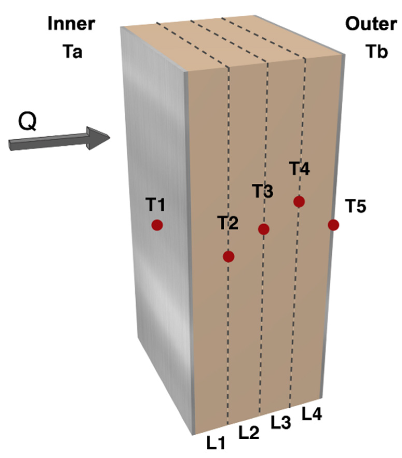
A set of type K thermocouples was used to register the temperature inside and outside the oven (Ta and Tb, respectively) and across the tested specimens (T1 to T5) (see red dots of Figure 5. Thermocouples T2, T3, and T4 were placed inside the sandwich panel at intervals of approximately a quarter of the thickness of the core material. Thermocouples T1 and T5 were positioned on the inner and outer panel surfaces, respectively. The thermocouples placed inside the sandwich core were inserted after drilling small cylindrical holes parallel to the test specimen surfaces. These holes were not in alignment, so the neighbouring holes would not affect the heat transfer, as shown in Figure 5.
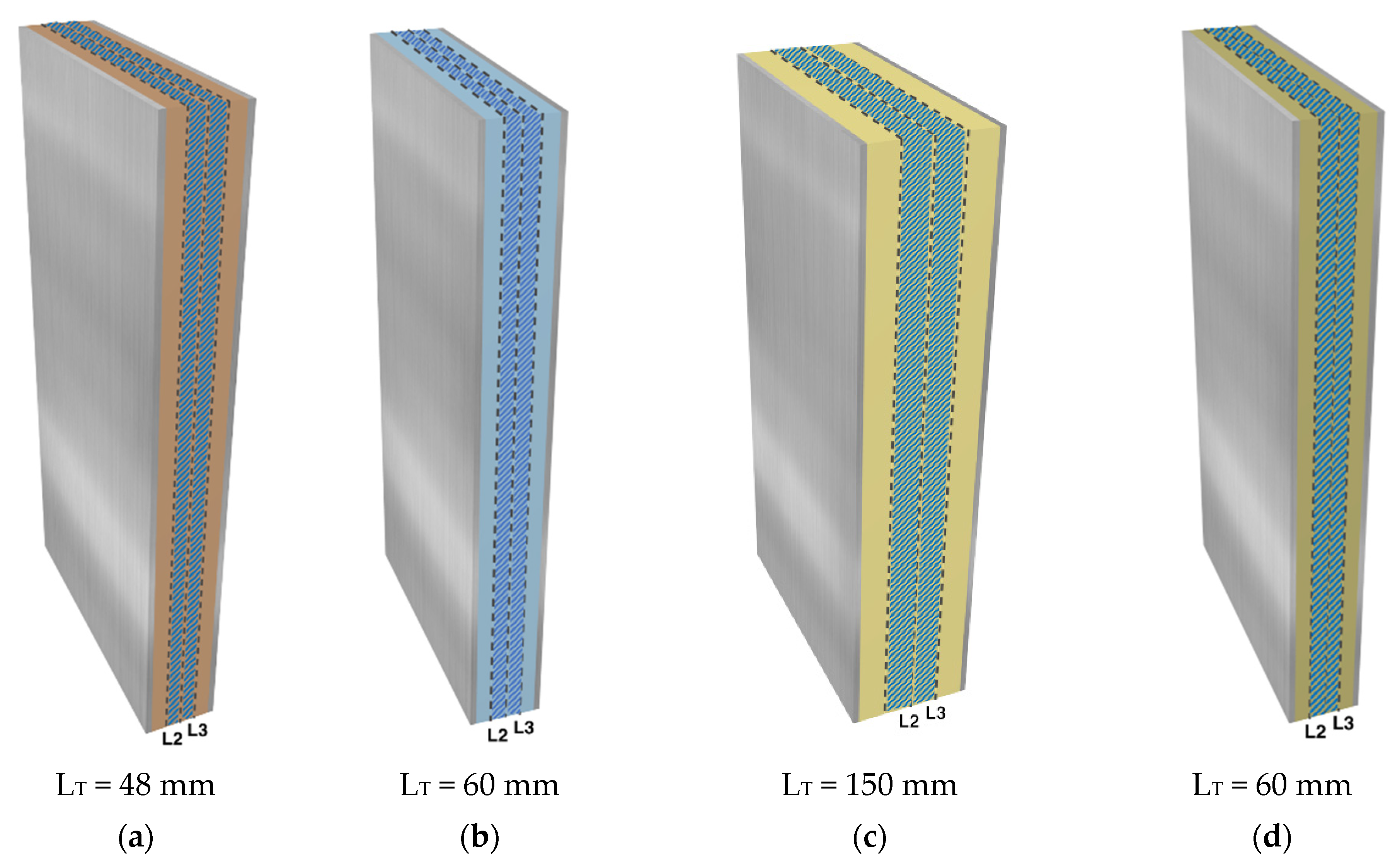
Apart from the temperature acquisition, heat fluxes were also recorded (Datalogger Keysight model 34970A with a module 34901A, Keysight, Santa Rosa, CA, USA). Two heat flux meters (Hukseflux Thermal Sensors FHF02SC-02, Hukseflux, Delft, Netherlands) were placed on each exterior panel’s surface. The data acquisition (temperature and heat fluxes) was carried out continuously throughout the test to enable the determination of thermal conductivity in each layer for each temperature step. The thermal conductivity was evaluated assuming that it remains constant between the inner layers of the core material, defined by the position of the thermocouples T2 and T3 (layer 2) and T3 and T4 (layer 3). The outer layers were excluded from the calculation since they form the double-layered system that incorporates the external steel sheets. Figure 6 shows a schematic representation of the four types of panels with the indication of the total nominal core thicknesses (LT) and the layers 2 and 3 highlighted in blue. Each panel only has one type of core.
The specific heat capacity (c) was evaluated using an indirect method. This method combined the experimental data with results from a one-dimensional analytical transient heat-transfer model, following the methodology proposed by Simões et al. (2012) [32]. It consists of using an iterative approach by aligning the experimental values registered by thermocouples with the analytical results.
The program inputs were the temperatures registered over time on the exterior faces, T1 and T5, and the middle panel temperature, T3 (see the thermocouple layout in Figure 2). Two layers were defined between the three thermocouples: a first layer (closer to the oven’s interior), which corresponds to layers 1 + 2 previously defined; and a second layer (further from the oven’s interior), which corresponds to 3 + 4. Apart from the temperatures recorded over time, it is necessary to define the positioning of the thermocouples, the thickness of the layers, and the properties of the materials (density and thermal conductivity). The methodology starts with an initial guess at the specific heat and by a reverse analysis that converges towards a specific heat value that corresponds to the best fit with experimental results. This best fit corresponds to the specific heat value that leads to the smallest mean squared error between the analytical and experimental temperature results (T3).
The specific heat was evaluated for each unsteady-state condition when the temperature in the oven changed to the next temperature level.
The thermal conductivity at 10 °C was also evaluated experimentally, following a standard procedure (by EN 12664 [30], in the case of balsa wood, and with EN 12667 [31] for the other materials), and compared with the results obtained using the methodology used for higher temperatures.

3.2. Young’s Modulus

Young’s modulus was determined by applying the impulse excitation technique following ASTM standard E 1876–15 [17]. This methodology has been used by several authors to determine the elasticity modulus [33,34,35], and it can be considered a simple and low-cost technique [13]. Typical techniques for the measurements of the Young’s modulus are destructive methods. This technique, apart from being non-destructive, can be easily used to determine the elastic modulus variation with temperature with only a small oven. Traditional procedures would be more challenging to implement because equipment such as displacement transducers or load cells would be exposed to high temperatures.
Parallelepiped test specimens were mechanically excited by a single impulse impact. The mechanical vibrations generated by the impact were detected by a piezoelectric sensor, previously bonded to the specimen. The recorded vibrations were then analysed and the fundamental bending resonant frequencies defined. A 20 mm piezo ceramic disc (Murata, Murata, Nagaoka, Japan) was used to assess the vibration response of each specimen. A digital oscilloscope (Picotech 3204, Picotech, Cambridgeshire, UK) was used for data acquisition.
The elastic modulus of parallelepiped test specimens was then evaluated according to the following equation:
E = 0.9465 ( m f f 2 w ) ( L 3 t 3 ) T 1
where
  • m—specimen mass (g);
  • ff—resonance frequency in bending (Hz);
  • w—width (mm);
  • L—length (mm);
  • t—thickness (mm);
T1—correction factor, whose formula can be found in the ASTM standard [17], for the fundamental flexural mode to account for the thickness and length of the test specimen and the and the Poisson’s ratio, μ. The correction factor T1 can be evaluated for specimens with a thickness/length (t/L) ratio greater than 0.20, using the following equation T 1 = [ 1.000 + 6.585 ( t L ) 2 ] , which only considers the thickness and length of the test specimen.
The test specimen was excited by being struck by a metal sphere with a diameter of 3 mm, which was introduced in the oven using a guiding tube. The specimen was suspended from a support. Figure 7 illustrates the test apparatus.

4. Results

4.1. Thermal Characterisation

Figure 8 shows the data registered for one specimen of each core material.
In order to determine the thermal conductivity, it was necessary to guarantee the existence of steady-state conditions (constant temperatures and heat fluxes), for each temperature step. As can be seen in Figure 8, the steps of 8 h allowed the stabilisation of the temperature in each layer. The data obtained between temperature levels (unsteady-state condition) were used to determine the specific heat.
The heat flux varies significantly for each test, since the thicknesses of the panels are different. In the case of the PUR’s thicker panel, the difference is more evident.
Figure 9 shows the test specimens’ condition after being tested. The PUR panels had clearly deteriorated after the test.
Table 3 and Table 4 present the mean values of thermal conductivity (λ) determined for the mean temperature (Tm) ranges (T3–T2 and T3–T4) for layers 2 and 3, respectively.
Figure 10 presents the same information graphically. The results for layer 3 and layer 2 are indicated with an asterisk and a circle, respectively. This figure also includes the best fit equations and the associated correlation coefficients.
It was assumed that the thermal conductivity computed is constant within each layer. This assumption is accurate when the temperature amplitude within a layer is very small. The PUR panels were the thickest specimens, and the temperature amplitude within each layer was larger.
For all tests, the thermal conductivity for layer 2 was found to be higher than it was for layer 3, because its temperature was higher.
The results recorded in the balsa wood tests exhibit higher variability, as the standard deviation results demonstrate. This was expected since balsa wood is a natural material and there is thus some heterogeneity in the material’s properties from panel to panel.
The thermal conductivity appears to exhibit non-linear behaviour as the temperature increases, for balsa wood and mineral wool. In these cases, the best fit equation is logarithmic.
The other materials, PUR and PET, exhibit linear behaviour. Both foams show a leap in thermal conductivity for higher temperatures. This increase is possibly related to the glass-transition temperature of the original polymers. Aside from that, at the end of test, the PUR panels exhibited deterioration of the material as can be seen in Figure 4. The moment or the temperature at which the damage started cannot be specified, but it certainly can be confirmed that this polymer foam cannot be used above 140 °C.
The thermal conductivity at 10 °C was also evaluated experimentally. The results are presented in Table 5. These results were compared with those obtained using the methodology for higher temperatures. They were found to agree with the thermal conductivity determined for the first temperature level, which validates the technique used. The results also show that the thermal conductivity does not seem to vary much within the temperature range 10 °C to 30 °C.
This process was repeated for all temperature jumps (5 steps) and for all the test specimens. Table 6 presents the mean value of specific heat for each material and each temperature step (mean).
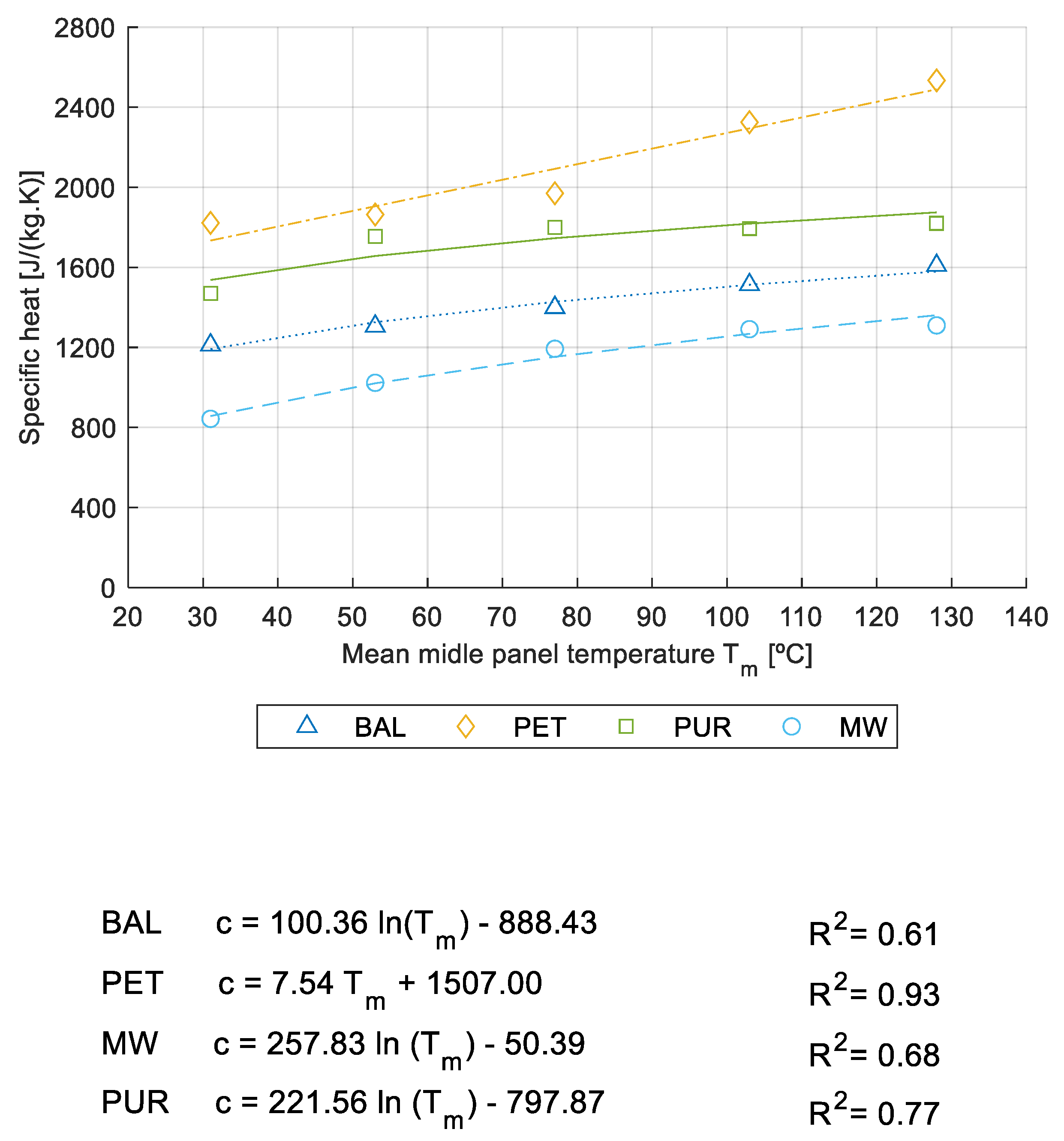
The results are also presented in graphic form in Figure 11 with the representation of the best fit equations and the relevant correlation coefficient. As with the thermal conductivity, the specific heat increased with temperature. Except for the PET, all materials presented non-linear behaviour as the temperature increased. The balsa wood and mineral wool seem to be the materials for which the specific heat is less affected by the rising temperature. The PET foam seems to be the most affected by temperature.

4.2. Young’s Modulus

The response was recorded in the time domain and transformed into the frequency domain by applying a fast Fourier transform (FFT). Figure 12 presents an example of a signal in the time and frequency domain. The highest peak corresponds to the first eigenmode in bending; the other peaks are related to higher eigenmodes.
Mineral wool was excluded from this test because this technique is not suitable for testing this kind of material. Given the small dimensions of the specimens and the damping characteristics of the material, it is not possible to cut parallelepiped-shaped samples of mineral wool and apply this technique.
The tests of the polymeric materials were carried out for temperatures up to 100 °C since this type of material starts to degrade at approximately this temperature. As the balsa wood can withstand higher temperatures, the tests were performed up to the maximum temperature supported by the piezoelectric sensor, 160 °C. At least three tests were performed at each temperature level. The tests were repeated 24 h after cooling to assess the capacity of the core material to be restored to its initial rigidity.
The IET results of the balsa wood specimens for different temperature levels are presented in Figure 13a. From the results we can see that the overall tendency of the elastic modulus is to decrease with temperature. However, a slight increase in the elastic modulus can be observed at 40 °C, possibly due to a reduction of humidity in the wood fibres. This increase in the elastic modulus was noted in both the longitudinal direction and in the transversal direction.
The elastic modulus obtained for the longitudinal direction (parallel to the grain) was much smaller than that recorded for the transversal direction, bearing out the large anisotropy assigned to the balsa wood, and wood in general [34].
The IET results of the PET and PUR samples, for different temperature levels, are presented in Figure 13b.
It can be observed that the temperature has a much greater influence on polymeric materials, particularly on PET, than on balsa wood. The Young’s modulus of the PET at 100 °C shows a reduction of 62% relative to ambient conditions for the transversal direction, and of 52% for the longitudinal direction. PUR samples have a Young’s modulus reduction of approximately 34% for the same temperatures. This is particularly important when foams of this kind have to ensure some structural resistance.
The PET foam does not seem to have a pronounced anisotropy, since the difference between the elastic modulus in the longitudinal and the transversal directions is not large.
The tests were repeated after cooling (after 24 h) and the materials either regained the initial value of the Young’s modulus or it was restored at a higher value. The thermal recovery property of wood species depends on the applied temperature. The elastic modulus reduction could be attributed to thermal softening rather than to thermal degradation [36]. Zhong et al. [37] found an improved residual elastic modulus for temperatures below 200 °C for Chinese larch. Regarding the polymeric foams, it is well known that the mechanical properties are significantly reduced at high temperatures, namely near the glass transition temperature (Tg). Thus, the Young’s modulus restored at a higher value for the foams is related to probable thermal degradation.

5. Conclusions

This work set out to perform a thermal and mechanical characterisation of four core materials often used in sandwich panels in climatic chambers, when exposed to a wide range of temperatures: balsa wood, mineral wool (MW), and two rigid foams, polyethylene terephthalate (PET) and polyurethane (PUR).
The thermal characterisation made use of an experimental setup developed to simulate a real application scenario in which one surface of the sandwich panels was subjected to high temperature, while the opposite surface was kept at room temperature. Steady and unsteady conditions were analysed up to 200 °C. In all cases, the thermal conductivity increased with temperature. This relation was found to be non-linear for the balsa and mineral wool, while the polymeric foams, PET and PUR, showed linear behaviour. When the temperature increased from 30 °C to 140 °C, the thermal conductivity doubled in the case of the PUR and grew 66% in the case of the PET. The two foams under study appeared to be more affected by temperature than the other materials. When the temperature increased from 30 °C to 140 °C, the thermal conductivity grew 28% in the case of the BAL and 61% in the case of the MW. In addition, it was found that the PUR panels were damaged, showing that this polymer foam cannot be used above 140 °C. The specific heat was evaluated using an indirect method previously developed by the authors. The specific heat results also increased with temperature, and the relation was found to be non-linear for all the tested materials except the PET, which showed linear behaviour with a higher increase in temperature (it grew 44% when the temperature increased from 30 °C to 130 °C).
The impulse excitation technique (IET) was used to determine the variation in Young’s modulus of these materials with temperature. The results showed that the tendency of the elastic modulus is to decrease with temperature (for example, the PUR 13.17 MPa at 23 °C to 9.07 MPa at 100 °C). It was confirmed that temperature had a more significant influence on the polymeric materials, particularly the PET (18.86 MPa at 23 °C to 9.03 MPa at 100 °C in the transversal direction; 20.37 MPa at 23 °C to 7.72 MPa at 100 °C in the longitudinal direction). However, the tests were repeated for polymeric foams and balsa wood after cooling for 24 h, and the materials had either regained the initial value of the Young’s modulus or its value had increased. This is an important outcome since the loss of stiffness is recoverable.
From a design standpoint it is particularly important to gain a sound understanding of how the thermal and mechanical properties are affected by the in-service temperature range. The authors suggest using a hybrid solution with a multi-layer of two materials, where one layer secures the thermal performance (mineral wool layer, for instance) and at the same time protects the mechanical resistance of the second layer from suffering loss of stiffness at high temperature. In some applications, this may require the use of a few mechanical connectors to transfer the load from one external face to the other.

Author Contributions

Conceptualization, S.D., A.T. and A.R.; methodology, S.D., A.T. and A.R.; software, M.B., F.P. and A.T.; validation, A.T. and A.R.; formal analysis, A.T. and A.R.; investigation, S.D., M.B. and F.P.; data curation, S.D. and F.P.; writing—review and editing, A.T., A.R. and M.B.; visualization, M.B. and F.P. All authors have read and agreed to the published version of the manuscript.

Funding

This research received no external funding.

Institutional Review Board Statement

Not applicable.

Informed Consent Statement

Not applicable.

Data Availability Statement

Not applicable.

Acknowledgments

The authors are grateful to the Project NewGenShell (POCI-01-0247-FEDER-033413) funded by Portugal 2020 through the Operational Programme for Competitiveness Factors (COMPETE2020).

Conflicts of Interest

The authors declare no conflict of interest.

References

  1. Naik, R.K.; Panda, S.K.; Racherla, V. A New Method for Joining Metal and Polymer Sheets in Sandwich Panels for Highly Improved Interface Strength. Compos. Struct. 2020, 251, 112661. [Google Scholar] [CrossRef]
  2. Keller, T.; Haas, C.; Vallée, T. Structural Concept, Design, and Experimental Verification of a Glass Fiber-Reinforced Polymer Sandwich Roof Structure. J. Compos. Constr. 2008, 12, 454–468. [Google Scholar] [CrossRef]
  3. Smardzewski, J. Wooden Sandwich Panels with Prismatic Core—Energy Absorbing Capabilities. Compos. Struct. 2019, 230, 111535. [Google Scholar] [CrossRef]
  4. Correia, J.R.; Garrido, M.; Gonilha, J.A.; Branco, F.A.; Reis, L.G. GFRP Sandwich Panels with PU Foam and PP Honeycomb Cores for Civil Engineering Structural Applications. Int. J. Struct. Integr. 2012, 3, 127–147. [Google Scholar] [CrossRef]
  5. de Freitas, S.T.; Kolstein, H.; Bijlaard, F. Sandwich System for Renovation of Orthotropic Steel Bridge Decks. J. Sandw. Struct. Mater. 2011, 13, 279–301. [Google Scholar] [CrossRef]
  6. Scislo, L.; Guinchard, M. Non-Invasive Measurements of Ultra-Ligtweight Composite Materials Using Laser Doppler Vibrometry System. In Proceedings of the 26 th International Congress on Sound and Vibration, Montreal, QC, Canada, 7–11 July 2019. [Google Scholar]
  7. Qiao, J.; Amirkhizi, A.V.; Schaaf, K.; Nemat-Nasser, S.; Wu, G. Dynamic Mechanical and Ultrasonic Properties of Polyurea. Mech. Mater. 2011, 43, 598–607. [Google Scholar] [CrossRef]
  8. Esmaeeli, R.; Farhad, S. Parameters Estimation of Generalized Maxwell Model for SBR and Carbon-Filled SBR Using a Direct High-Frequency DMA Measurement System. Mech. Mater. 2020, 146, 103369. [Google Scholar] [CrossRef]
  9. Ramorino, G.; Vetturi, D.; Cambiaghi, D.; Pegoretti, A.; Ricco, T. Developments in Dynamic Testing of Rubber Compounds: Assessment of Non-Linear Effects. Polym. Test. 2003, 22, 681–687. [Google Scholar] [CrossRef]
  10. Renaud, F.; Chevallier, G.; Dion, J.-L.; Lemaire, R. Viscoelasticity Measurement and Identification of Viscoelastic Parametric Models. In Biennial Conference on Mechanical Vibration and Noise, Parts A and B, 23rd ed.; ASMEDC: Washington, DC, USA, 2011; Volume 1, pp. 701–708. [Google Scholar] [CrossRef]
  11. Lord, J.D.; Morrell, R.M. Comparison of Static and Dynamic Methods for Measuring Stiffness of High Modulus Steels and Metal Composites. Can. Metall. Q. 2014, 53, 292–299. [Google Scholar] [CrossRef]
  12. Massara, N.; Boccaleri, E.; Milanesio, M.; Lopresti, M. IETeasy: An Open Source and Low-Cost Instrument for Impulse Excitation Technique, Applied to Materials Classification by Acoustical and Mechanical Properties Assessment. HardwareX 2021, 10, e00231. [Google Scholar] [CrossRef]
  13. Tognana, S.; Salgueiro, W.; Somoza, A.; Marzocca, A. Measurement of the Young’s Modulus in Particulate Epoxy Composites Using the Impulse Excitation Technique. Mater. Sci. Eng. A 2010, 527, 4619–4623. [Google Scholar] [CrossRef]
  14. Bahr, O.; Schaumann, P.; Bollen, B.; Bracke, J. Young’s Modulus and Poisson’s Ratio of Concrete at High Temperatures: Experimental Investigations. Mater. Des. 2013, 45, 421–429. [Google Scholar] [CrossRef]
  15. Zhang, J.; Nyilas, A.; Obst, B. New Technique for Measuring the Dynamic Young’s Modulus between 295 and 6 K. Cryogenics 1991, 31, 884–889. [Google Scholar] [CrossRef]
  16. Guan, C.; Liu, J.; Zhang, H.; Wang, X.; Zhou, L. Evaluation of Modulus of Elasticity and Modulus of Rupture of Full-Size Wood Composite Panels Supported on Two Nodal-Lines Using a Vibration Technique. Constr. Build. Mater. 2019, 218, 64–72. [Google Scholar] [CrossRef]
  17. ASTM E 1876-15; Standard Test Method for Dynamic Young’s Modulus, Shear Modulus, and Poisson’s Ratio by Im-Pulse Excitation of Vibration. ASTM: West Conshehoken, PE, USA, 2015.
  18. Zhang, S.; Dulieu-Barton, J.M.; Thomsen, O.T. The Effect of Temperature on the Failure Modes of Polymer Foam Cored Sandwich Structures. Compos. Struct. 2015, 121, 104–113. [Google Scholar] [CrossRef] [Green Version]
  19. Garrido, M.; Correia, J.R.; Keller, T. Effects of Elevated Temperature on the Shear Response of PET and PUR Foams Used in Composite Sandwich Panels. Constr. Build. Mater. 2015, 76, 150–157. [Google Scholar] [CrossRef]
  20. Vahedi, N.; Wu, C.; Vassilopoulos, A.P.; Keller, T. Thermomechanical Characterization of a Balsa-Wood-Veneer Structural Sandwich Core Material at Elevated Temperatures. Constr. Build. Mater. 2020, 230, 117037. [Google Scholar] [CrossRef]
  21. Khoukhi, M.; Fezzioui, N.; Draoui, B.; Salah, L. The Impact of Changes in Thermal Conductivity of Polystyrene Insulation Material under Different Operating Temperatures on the Heat Transfer through the Building Envelope. Appl. Therm. Eng. 2016, 105, 669–674. [Google Scholar] [CrossRef]
  22. Quintana, J.M.; Mower, T.M. Thermomechanical Behavior of Sandwich Panels with Graphitic-Foam Cores. Mater. Des. 2017, 135, 411–422. [Google Scholar] [CrossRef]
  23. Jelle, B.P. Traditional, State-of-the-Art and Future Thermal Building Insulation Materials and Solutions—Properties, Requirements and Possibilities. Energy Build. 2011, 43, 2549–2563. [Google Scholar] [CrossRef] [Green Version]
  24. Berardi, U. The Impact of Aging and Environmental Conditions on the Effective Thermal Conductivity of Several Foam Materials. Energy 2019, 182, 777–794. [Google Scholar] [CrossRef]
  25. Zhang, H.; Fang, W.-Z.; Li, Y.-M.; Tao, W.-Q. Experimental Study of the Thermal Conductivity of Polyurethane Foams. Appl. Therm. Eng. 2017, 115, 528–538. [Google Scholar] [CrossRef]
  26. Huang, P.; Chew, Y.M.J.; Chang, W.-S.; Ansell, M.P.; Lawrence, M.; Latif, E.; Shea, A.; Ormondroyd, G.; Du, H. Heat and Moisture Transfer Behaviour in Phyllostachys Edulis (Moso Bamboo) Based Panels. Constr. Build. Mater. 2018, 166, 35–49. [Google Scholar] [CrossRef]
  27. Asdrubali, F.; D’Alessandro, F.; Schiavoni, S. A Review of Unconventional Sustainable Building Insulation Materials. Sustain. Mater. Technol. 2015, 4, 1–17. [Google Scholar] [CrossRef]
  28. EN 1602; Thermal Insulating Products for Building Applications. Determination of the Apparent Density. BSI: London, UK, 2013.
  29. EN 823; Thermal Insulating Products for Building Applications. Determination of Thickness. BSI: London, UK, 2013.
  30. EN 12664; Thermal Performance of Building Materials and Products—Determination of Thermal Resistance by Means of Guarded Hot Plate and Heat Flow Meter Methods. Dry and Moist Products of Medium and Low Thermal Resistance. BSI: London, UK, 2001.
  31. EN 12667; Thermal Performance of Building Materials and Products. Determination of Thermal Resistance by Means of Guarded Hot Plate and Heat Flow Meter Methods. Products of High and Medium Thermal Resistance. BSI: London, UK, 2001.
  32. Simões, I.; Simões, N.; Tadeu, A. Thermal Delay Simulation in Multilayer Systems Using Analytical Solutions. Energy Build. 2012, 49, 631–639. [Google Scholar] [CrossRef]
  33. Sinha, A.; Morrell, J.J.; Clauson, M. Use of Acoustic Assessment to Detect Decay and Assess Condition of Wooden Guardrail Posts. For. Prod. J. 2015, 65, 314–319. [Google Scholar] [CrossRef]
  34. Dinckal, C. Analysis of Elastic Anisotropy of Wood Material for Engineering Applications. J. Innov. Res. Eng. Sci. 2011, 67–80. [Google Scholar]
  35. Paolino, D.S.; Geng, H.; Scattina, A.; Tridello, A.; Cavatorta, M.P.; Belingardi, G. Damaged Composite Laminates: Assessment of Residual Young’s Modulus through the Impulse Excitation Technique. Compos. Part B Eng. 2017, 128, 76–82. [Google Scholar] [CrossRef]
  36. Kucíková, L.; Šejnoha, M.; Janda, T.; Sýkora, J.; Padevět, P.; Marseglia, G. Mechanical Properties of Spruce Wood Extracted from GLT Beams Loaded by Fire. Sustainability 2021, 13, 5494. [Google Scholar] [CrossRef]
  37. Young, Z.; Zhou, H.; Wen, L. The Effect of Elevated Temperature on Bending Properties of NormalWood inside Chinese Larch Wood during Fire Events. BioResources 2015, 10, 2926–2935. [Google Scholar]
Figure 1. Photographic record of the test specimens: (a) MW core; (b) PUR core; (c) PET core; (d) balsa wood core.
Energies 15 02089 g001
Figure 2. IET test specimens: (a) BAL sample; (b) PET sample; (c) PUR sample.
Energies 15 02089 g002
Figure 3. A detailed drawing of the oven door modifications: (a) 3D scheme; (b) drawing of the door modification (front view); (c) drawing of the door modification (side view—section B–B).
Energies 15 02089 g003
Figure 4. Photographic register of the oven door modifications.
Energies 15 02089 g004
Figure 5. Schematic representation of test specimen, where Ta and Tb represent the thermocouples’ exterior positions (inside and outside the oven, respectively); Ti (I = 1 to 5) denotes the thermocouples in the panel; Li (i = 1 to 4) identifies the layers; and Q is the heat flux in the direction indicated by the arrow.
Energies 15 02089 g005
Figure 6. Schematic representation of the panels: (a) BAL panel; (b) PET panel; (c) PUR panel; (d) MW panel.
Energies 15 02089 g006
Figure 7. Test apparatus: (a) scheme; (b) photographic record.
Energies 15 02089 g007
Figure 8. Examples of temperature and heat flux recorded during the test: (a) BAL panel; (b) PET panel; (c) PUR panel; (d) MW panel.
Energies 15 02089 g008aEnergies 15 02089 g008b
Figure 9. Photos of each type of material and its condition after being tested: (a) BAL; (b) PET; (c) PUR; (d) MW.
Energies 15 02089 g009
Figure 10. Thermal conductivity/layer temperature (mean values): (a) BAL panels; (b) PET panels; (c) PUR panels; (d) MW panels.
Energies 15 02089 g010
Figure 11. Specific heat/mean temperature register.
Energies 15 02089 g011
Figure 12. Example of a recorded signal obtained with the specimen PET-T at 70 °C: (a) in time domain; (b) in frequency domain.
Energies 15 02089 g012
Figure 13. Variation in the elastic modulus with temperature (mean values and standard deviation): (a) balsa; (b) PUR and PET.
Energies 15 02089 g013
Table 1. Description of the studied materials.
Balsa WoodPolyethylene Terephthalate FoamPolyurethane FoamMineral Wool
Energies 15 02089 i001 Energies 15 02089 i002 Energies 15 02089 i003 Energies 15 02089 i004
DescriptionCore material produced from select kiln-dried balsa wood in the ‘end-grain’ configurationStructural lightweight PET foam boards made of 100% recycled PETRigid foam of PURock wool panel made of basalt, slag, and briquet (recycled stone wool)
Density (kg/m3) **174.6 ± 30.56
(Grain direction) *
98.30 ± 0.4641.2 ± 1.099.2 ± 0.56
Thickness (mm) **48 ± 1.0560 ± 0.90150 ± 0.8560 ± 0.93
* The density, stiffness, and strength in the grain direction are considerably higher than in any other direction. ** The values presented correspond to the mean and the standard deviation of three test specimen results.
Table 2. IET test specimens’ physical characteristics and dimensions (the mean and the standard deviation of three test specimens).
SpecimenBalsa Longitudinal Direction
(BAL-L)
Balsa Transversal Direction
(BAL-T)
PUR
(PUR)
PET Longitudinal Direction
(PET-L)
PET Transversal Direction
(PET-T)
m (g)0.8672 ± 0.0170.9531 ± 0.0110.6144 ± 0.0361.1242 ± 0.0141.123 ± 0.021
L (mm)99.07 ± 1.0099.36 ± 1.18100.89 ± 0.41101.59 ± 0.54101.35 ± 0.73
w (mm)25.17 ± 0.5520.69 ± 1.5224.82 ± 0.5325.36 ± 0.825.44 ± 0.50
t (mm)2.21 ± 0.134.73 ± 0.344.91 ± 0.1034.99 ± 0.354.96 ± 0.45
L/t45 ± 1.021 ± 121 ± 121 ± 121 ± 1
T11.0034 ± 0.00031.0152 ± 0.00241.0158 ± 0.000631.0169 ± 0.00161.0173 ± 0.0022
Density (kg/m3)156 ± 1098 ± 150 ± 187 ± 188 ± 1
Table 3. Thermal conductivity ( W / ( m · K ) ) evaluated for layer 2 (the mean and the standard deviation of three test specimens).
BALPET
Tm (°C) λ   ( W / ( m · K ) ) Tm (°C) λ   ( W / ( m · K ) )
33 ± 0.70.1146 ± 0.00334 ± 1.20.0382 ± 0.004
58 ± 2.50.1237 ± 0.01163 ± 2.30.0444 ± 0.006
83 ± 4.40.1291 ± 0.01693 ± 5.20.0485 ± 0.006
109 ± 5.00.1342 ± 0.017124 ± 6.10.0670 ± 0.011
134 ± 7.10.1327 ± 0.018155 ± 6.30.0750 ± 0.012
PURMW
Tm (°C) λ   ( W / ( m · K ) ) Tm (°C) λ   ( W / ( m · K ) )
32 ± 2.10.0211 ± 0.00134 ± 0.90.0378 ± 0.003
58 ± 3.20.0275 ± 0.00562 ± 2.30.0520 ± 0.003
85 ± 2.90.0314 ± 0.00892 ± 1.50.0555 ± 0.004
114 ± 4.50.0392 ± 0.013122 ± 1.20.0553 ± 0.008
146 ± 6.30.0402 ± 0.014152 ± 2.30.0642 ± 0.010
Table 4. Thermal conductibility ( W / ( m · K ) ) evaluated for layer 3 (the mean and the standard deviation of three test specimens).
BALPET
Tm (°C) λ   ( W / ( m · K ) ) Tm (°C) λ   ( W / ( m · K ) )
31 ± 0.90.0963 ± 0.01930 ± 2.60.0397 ± 0.002
51 ± 0.90.105 ± 0.01652 ± 3.00.0432 ± 0.002
69 ± 1.20.1142 ± 0.02676 ± 3.20.0453 ± 0.008
89 ± 2.40.115 ± 0.029102 ± 5.90.0561 ± 0.014
108 ± 3.10.122 ± 0.035128 ± 6.00.0603 ± 0.017
PURMW
Tm (°C) λ   ( W / ( m · K ) ) Tm (°C) λ   ( W / ( m · K ) )
26 ± 3.20.0182 ± 0.00128 ± 01.30.0377 ± 0.002
42 ± 2.30.0228 ± 0.00145 ± 3.20.0470 ± 0.002
57 ± 4.50.0251 ± 0.00163 ± 4.20.0483 ± 0.003
74 ± 5.70.0261 ± 0.00282 ± 5.30.0539 ± 0.005
93 ± 7.60.0285 ± 0.003101 ± 7.20.0606 ± 0.007
Table 5. Results of thermal conductivity (W/(m·K) of the core materials at 10 °C (the mean and the standard deviation of three test specimens).
BALPETPURMW
Apparent density (kg/m3) 174.6 ± 30.5698.30 ± 0.4641.2 ± 1.099.2 ± 0.56
Thermal conductivity
( W / ( m · K ) )
0.1158 ± 0.02020.0396 ± 0.00140.019 ± 0.0010.0366 ± 0.0016
Table 6. Results of the specific heat (J/(kg·K)) using the indirect methodology (the mean and the standard deviation of three test specimens).
BALPET
Tm (°C)c (J/(kg·K))Tm (°C)c (J/(kg·K))
32 ± 1.41212 ± 230 ± 2.01822 ± 2
54 ± 2.91306 ± 1152 ± 2.51864 ± 4
80 ± 3.31399 ± 777 ± 3.11970 ± 3
104 ± 2.71513 ± 4105 ± 2.82325 ± 5
127 ± 2.11609 ± 10130 ± 3.42534 ± 8
PURMW
Tm (°C)c (J/(kg·K))Tm (°C)c (J/(kg·K))
29 ± 1.41470 ± 131 ± 1.5 843 ± 9
50 ± 2.91755 ± 354 ± 1.91023 ± 5
72 ± 3.31799 ± 578 ± 2.41193 ± 7
99 ± 2.71794 ± 2104 ± 3.31291 ± 4
126 ± 3.11820 ± 2129 ± 3.21310 ± 6
Publisher’s Note: MDPI stays neutral with regard to jurisdictional claims in published maps and institutional affiliations.