Abstract
The efficiency of light-duty diesel engines should be improved for further emissions regulation. Multi-stage split injection with five injection events was investigated for improvement in efficiency at low-load conditions. The injection timing and quantity were adjusted to achieve a smooth in-cylinder pressure rise and continuous heat release. The multi-stage split injection was compared to injection strategies involving two-pilot and single-main injections. A 0.5 L single-cylinder diesel engine experiment was conducted under low-load conditions. Two multi-stage split injection processes with different combustion phases were developed. The multi-stage split injections yielded a smooth in-cylinder pressure trace and a lower peak heat release rate than the two-pilot injection process. The combustion duration was shorter for multi-stage split injection with an advanced combustion phase, and the fuel consumption was reduced by 1.78% with lower heat transfer, exhaust heat, and combustion loss. The multi-stage split injection flame penetration was shorter than the two-pilot injections. The shorter flame penetration and lower tip velocity reduced the heat transfer to the combustion chamber. The PM emissions were also reduced by 30% under the same NOx emissions, because increased PM oxidation and divided fuel injection prevented flame diffusion and improved air utilization.
1. Introduction
Diesel engines generally have higher efficiencies and torques than spark-ignition engines because of their high compression ratios and lean-burn operation [1]. However, nitrogen oxide (NOx) and particulate matter (PM) emissions must be managed to conform to emission standards [2,3]. Additionally, future regulations will require further fuel economy improvement and emission reduction for diesel engines. Accordingly, various studies have focused on refinements to diesel-engine components to reduce fuel consumption and engine-out emissions.
The multiple injection method is an essential technique for modern common-rail diesel engines [4]. Diesel engines use multiple injection events for various purposes. Usually, most of the fuel for the engine cycle is injected in the main injection event. The pilot injections control the NOx and PM emissions and limit the combustion noise, peak cylinder pressure, and exhaust temperature. The post injections control the PM emissions and exhaust gas temperature for after-treatment or turbocharger systems [5]. Previously, Hotta et al. [6] reported that post-injection provides additional energy, which improves mixing and enhances the soot oxidation process at the end of the combustion process. They also reported that post-injection increases the temperature in the combustion chamber and the soot oxidation rate.
With improvements in manufacturing technology, some fuel injection equipment manufacturers have incorporated the closely coupled pilot injection method [7,8]; this technique reduces combustion noise by simultaneously maintaining or reducing soot emissions. In particular, closely coupled pilot injection and multiple injections have been found to shape the combustion rate and reduce combustion noise [9,10,11]. Denny et al. [12,13,14] investigated the combustion phenomenon and noise reduction of closely coupled triple-pilot injection in a series of studies. They examined the effects of triple-pilot injection strategies with various dwell times less than 100 μs and found that high partially oxidized fuel fractions are achieved when the injections occur at short intervals. Their findings indicate that fuel injections impact the prevailing combustion regions, with hotter combustion products replacing cooler combustion products. Additionally, triple-pilot injection strategies yield noise reduction despite the increased maximum pressure rise rate (MPRR). They also showed that the combustion noise is correlated with the dip or valley in the heat release rate with a deep valley yielding higher noise.
The term “split injection” usually refers to a process of multiple injections, where the main injection is divided into two or more injections. In several studies, Ewphun et al. [15,16] utilized multi-pulse split injection for peak heat release reduction and thermal efficiency improvement in premixed-charge compression ignition (PCCI) combustion. The injection strategies included two-pilot injections and a split main injection, where the latter was divided into 2–4 pulses. The four-pulse main injection process yielded prolonged combustion in the expansion stroke and degraded thermal efficiency; however, the three-pulse main injection setup effectively reduced the peak heat release rate and improved the thermal efficiency. Similarly, Yang et al. [17] investigated combustion with the main injection split into two injections. The second injection caught the presenting flame, thereby deteriorating the combustion process and increasing soot formation. To date, studies on split-injection strategies have typically focused on the consequences of split-injection strategies with evenly divided injection quantities. Moreover, the efficiency improvement due to the implementation of a split-injection strategy in a conventional diesel combustion process under low-load conditions via flame visualization has been reported rarely, compared to the studies on multiple-injection strategies including the pilot, main, and post-injections [5]. Improving the efficiency under low-load operation is important because low-load conditions are the main operation points in a light-duty diesel engine.
A further understanding of the effect of multi-stage split injection on efficiency and emissions is required. The primary aim of this study was to analyze the effects of multi-stage split (MSS) injection in a light-duty diesel engine under low load in terms of combustion formation and energy balance. Thus, an MSS injection strategy was established to smooth the in-cylinder pressure from the combustion, maintaining the combustion phase. Comparing fuel efficiency and exhaust emissions from various injection strategies maintaining the combustion phase is important so that the effects of injection strategies can be verified clearly. The flame penetration behavior was observed for several injection strategies to analyze the heat transfer loss. In addition, heat balance analysis was performed, and the PM emissions were investigated.
2. Materials and Methods
The experimental apparatus and conditions for the paper are described in this section. The injection system, injectors, single-cylinder diesel engine, and a constant-volume combustion chamber were utilized for engine and flame visualization experiments.
2.1. Injection System and Injectors
The fuel injection equipment (FIE) was modified for single-cylinder engine operation. A common-rail fuel pump from a commercial diesel engine was used. An electric motor was employed to drive the high-pressure fuel pump, and a modified engine control unit was used to control the injector and fuel pump. The fuel flow rate was determined using a Coriolis flowmeter (Bronkhorst mini CORI-FLOW). The fuel-tank temperature was maintained at 313 K. A solenoid-type injector was tested in this work; this injector is a variant of the conventional injector used in light-duty diesel engines. Its specifications are listed in Table 1.

Table 1.
Injector specifications.
The injection rate was measured using the Bosch long-tube method [18,19,20]. In detail, the pressure waves produced by fuel injection into a long tube containing compressible fluid were measured. The backpressure was maintained at 20 bar using a relief valve, and the tube pressure was measured with a piezoelectric pressure transducer (Kistler, Winterthur, Switzerland, 6052C) coupled with a charge amplifier (Kistler, 5011). Figure 1 shows a schematic of the injection-rate measurement system used in the experiments.
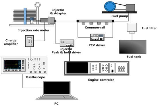
Figure 1.
Schematic of injection-rate meter system (PCV: pressure control valve).
2.2. Single-Cylinder Diesel Engine
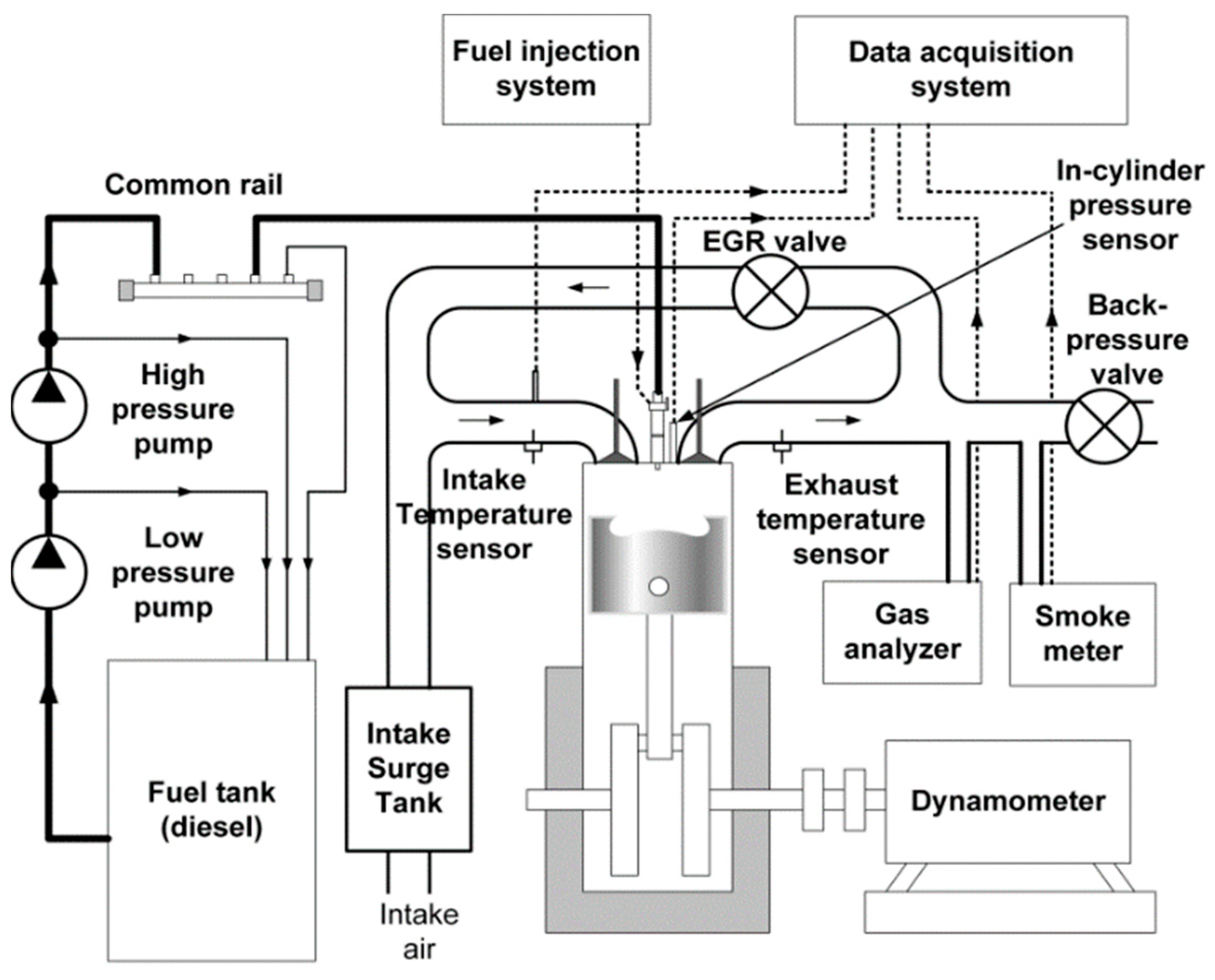
The engine experiments were performed on a 0.5 L single-cylinder compression ignition diesel engine modified from a commercial 2.0 L four-cylinder diesel engine. The piston bowl had a stepped-lip design [21], and conventional diesel was used as fuel. A schematic and detailed specifications of the engine apparatus are presented in Figure 2 and Table 2, respectively. A direct current dynamometer was used to maintain the engine speed.

Figure 2.
Schematic of 0.5 L single-cylinder diesel engine; EGR: exhaust gas recirculation.
Table 2.
Specifications of 0.5 L single-cylinder diesel engine.
The gaseous NOx, HC, and CO emissions were measured using an exhaust gas analyzer (Horiba, MEXA-7100D). The black smoke emissions were measured using a filter smoke number meter (AVL, 415S) to estimate the PM emissions. An exhaust gas recirculation (EGR) valve was installed between the intake and exhaust manifolds to control the EGR. The in-cylinder pressure was measured in crank angle degree (CAD) increments of 0.2 using a piezoelectric pressure transducer (Kistler, 6056A) installed at the glow plug position. Pressure data were acquired with a charge amplifier (Kistler, 5011). The heat release rate was obtained from the in-cylinder pressure profile averaged over 100 engine cycles via the following equation [22]:
In general, the energy balance can be determined from the measured compositions and temperatures of the intake and exhaust gases. The thermal balance equation for a cylinder can be expressed as [23]:
where () is the fuel heating value, is the intake-gas enthalpy, is the indicated engine power, is the heat transfer loss, is the exhaust-gas enthalpy, and is the combustion loss due to the incomplete combustion. The difference between and is the exhaust loss. and can be calculated from the intake- and exhaust-gas mass flow rates, temperature, compositions, and specific heat capacities via the following equations:
where and are the mass flow rates, and are the specific heat capacities, and and are the temperatures of the intake and exhaust gases, respectively. In this work, the enthalpy of each component was calculated from the NIST Chemistry WebBook [24].
Finally, can be calculated from the chemical energy of the unburned products (HC and CO) in the exhaust gas, and can be derived by subtracting , exhaust loss, and from .
Table 3 lists the engine’s experimental conditions. Under each experimental condition, the injection quantity was regulated to maintain the indicated mean effective pressure (IMEP). The EGR was applied in terms of NOx concentration. The EGR was increased until the NOx concentration reached 200 ppm.
Table 3.
Experimental conditions for engine experiments; IMEP: indicated mean effective pressure.
2.3. Constant-Volume Combustion Chamber for Combustion Visualization
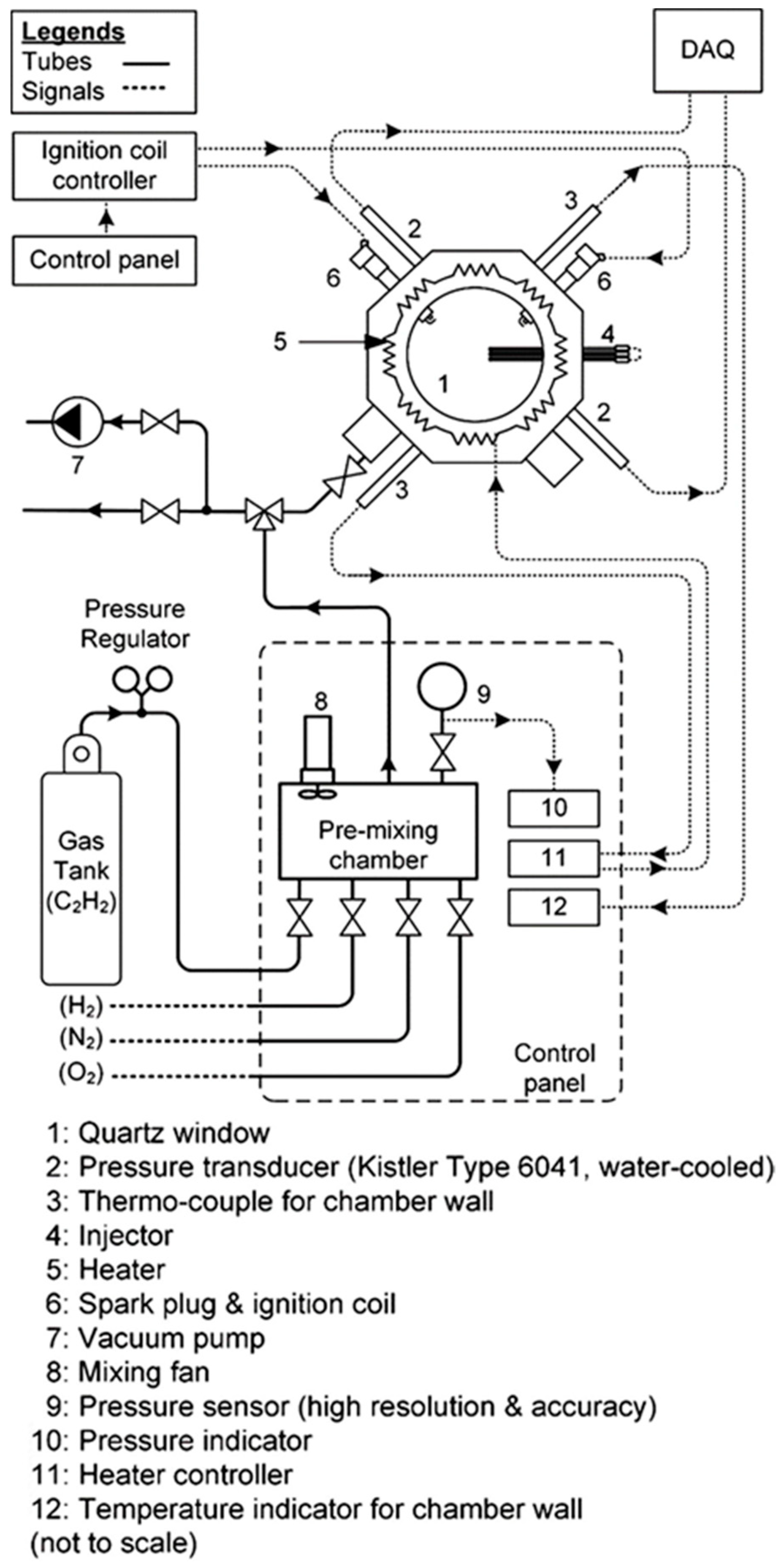
Figure 3 shows the constant-volume combustion chamber (CVCC) used for flame penetration measurement. Here, ambient temperature and pressure similar to those in an actual diesel engine were simulated. The CVCC specifications are listed in Table 4. Following pre-mixture formation using hydrogen (H2), acetylene (C2H2), oxygen (O2), and nitrogen (N2), the pre-mixture was ignited by two spark plugs from each side of the chamber. The initial chamber temperature was maintained at 473 K to ensure complete pre-combustion. The pre-burn procedure was performed with reference to the Engine Combustion Network [25,26]. After ten iterations of the pre-burn test, the injection timing was determined based on the average time at which the chamber pressure reached the target pressure following the spark timing for pre-burn. The chamber pressure was sampled at 100 kHz frequency using a piezoelectric pressure transducer (Kistler, 6141B). Simultaneously, spray images were captured using a high-speed camera (Vision Research Inc., Phantom VEO 710L). The high-speed camera shutter speed was 20,000 frames per second, implying that images were captured at 50 μs intervals. The lens used for the experiment was Nikon 28–70 mm f/3.5–4.5 AF. The f-number was 11 for the flame visualization.

Figure 3.
Constant volume combustion chamber (CVCC); DAQ: data acquisition system.
Table 4.
CVCC specifications.
The target oxygen concentration after the pre-burn was 15% to simulate the EGR condition. The target CVCC temperature and pressure were 973 K and 50 bar, respectively. The injection quantity and pressure were fixed at 14.3 mg and 650 bar, respectively. During each chamber experiment, the pre-burn pressure was measured using a data acquisition (DAQ) system, and the fuel was injected at a predetermined time after the spark. When the measured pressure in the chamber satisfied 50 bar within an error range of 0.5% at the start of injection, this measurement was accepted as a valid data point; a total of 5 valid data points were acquired. The flame penetration was averaged from the results of five repeated experiments.
3. Results
3.1. Multi-Stage Split Injection
The MSS injection for improved engine efficiency was investigated. The injection quantities and timings were adjusted to maintain the slope of the pressure trace from the combustion as that of the motoring pressure. The injection parameters were adjusted to yield the target combustion phase. The minimum interval between injection signals was 300 μs, as this was the solenoid-injector operating margin. Note that if the interval between injections is too short, the injections become unstable.
This injection strategy requires divided injections, because it aims for the combustion to be distributed rather than concentrated with continuous heat release. However, due to the minimum injection interval described above, five injection events would require an actual spray duration of at least 25 CAD. If the number of injections is larger than that, the overall fuel supply time is extended, and the combustion period is prolonged, which adversely affects fuel efficiency. Therefore, five injection events at 1500 rpm were determined. This study presented the injection profiles with a smooth pressure rise and suppressed MPRR by conducting a parametric study while monitoring the combustion shape.
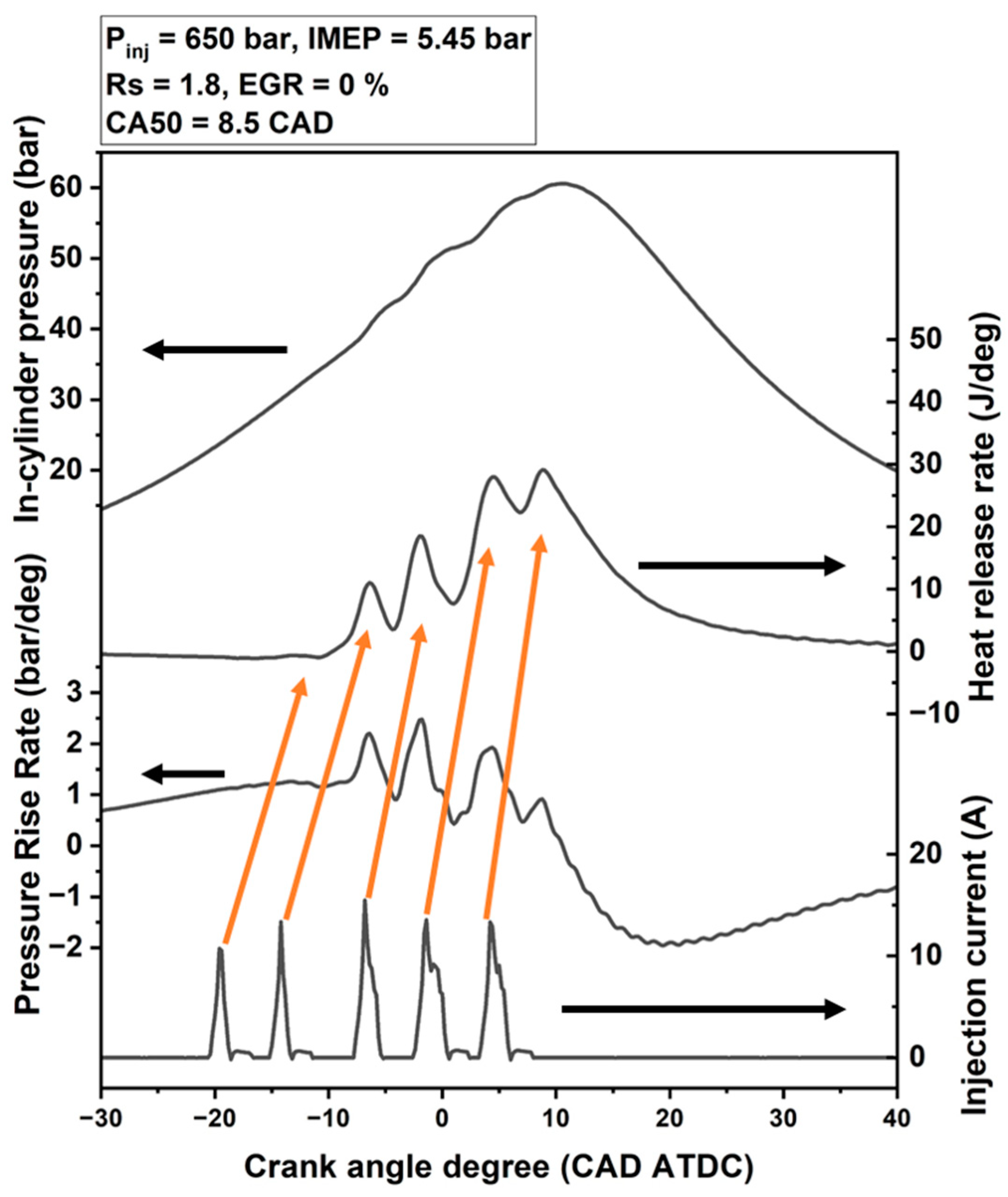
Figure 4 shows the in-cylinder pressure trace, heat release rate, pressure rise rate, and injection current for the MSS injection strategy in the single-cylinder engine. Because the injection quantities and timings were set to yield a smooth in-cylinder pressure trace, the in-cylinder pressure continuously increased from 10 CAD BTDC (before top dead center) to 10 CAD ATDC (after top dead center). The MSS injection was composed of five injections as indicated by the circled numbers in Figure 4. The first and second injections had short injection durations and small injection quantities. In comparison, the third to fifth injections had longer injection durations and larger injection quantities. The heat release rate trend exhibited several peaks in response to the injections. In detail, the first injection showed negligible heat release and the second injection yielded the first notable heat release rate peak. The third to fifth injections each yielded subsequent heat release peaks, as indicated by the arrows in Figure 4. The pressure rise rate is shown in the third (bottom) profile of Figure 4. Even though the heat releases from the fourth and fifth injections were high, the MPRR was from the heat release of the third injection as this result was before and near TDC.

Figure 4.
The in-cylinder pressure, heat release rate, pressure rise rate, and injection current of the MSS injection.
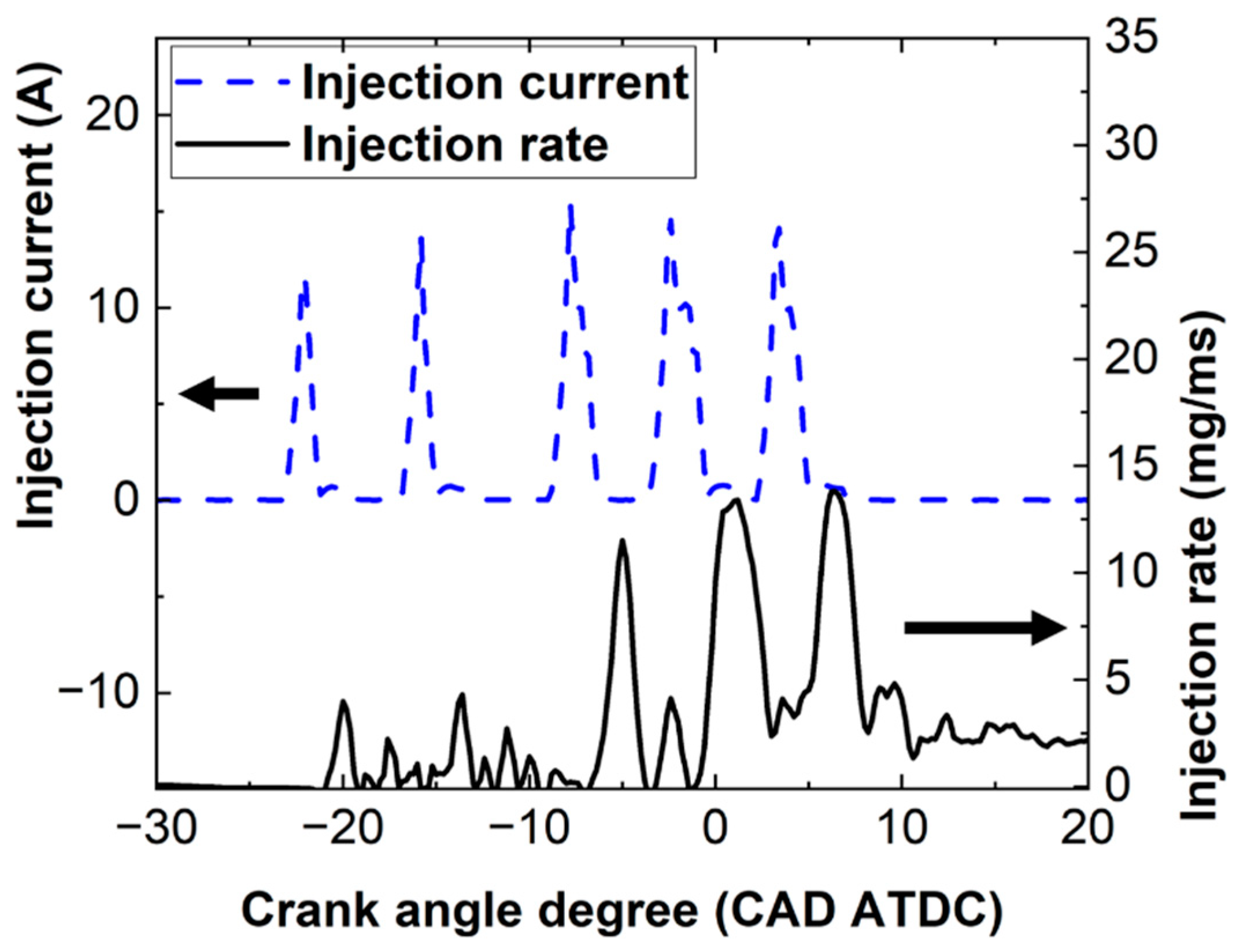
Figure 5 shows the measured injection current and averaged injection rate from the Bosch tube method. The injection rate was acquired from 100 repeats. The average peak injection rate of the first injection was 4.7 mg/ms, and the standard deviation was 0.1656. Thus, the injector maintained the uniform injection rate and quantity from each injection cycle. The actual injection was started after 275 μs from the injection signal starts. Table 5 is the measured injection quantity from the MSS injection strategy. The injection quantity from the fourth injection occupied the highest proportion. The injection rate profiles include the needle rebound and pressure oscillations in the tube.
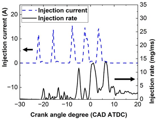
Figure 5.
Injection rate profile of the MSS injection strategy.
Table 5.
Injection quantity for each MSS injection event.
3.2. Combustion of the Multi-Stage Split-Injection Process
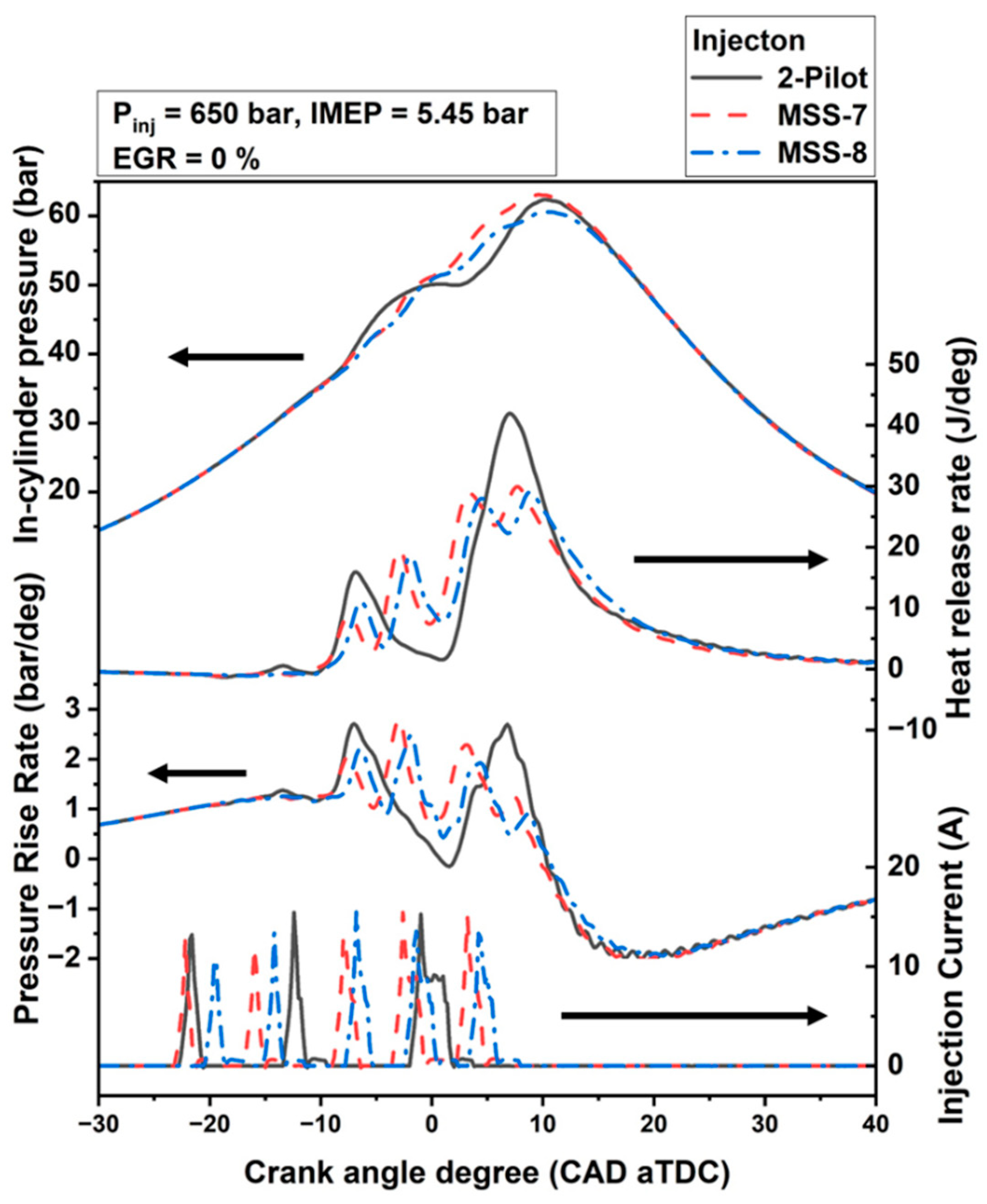
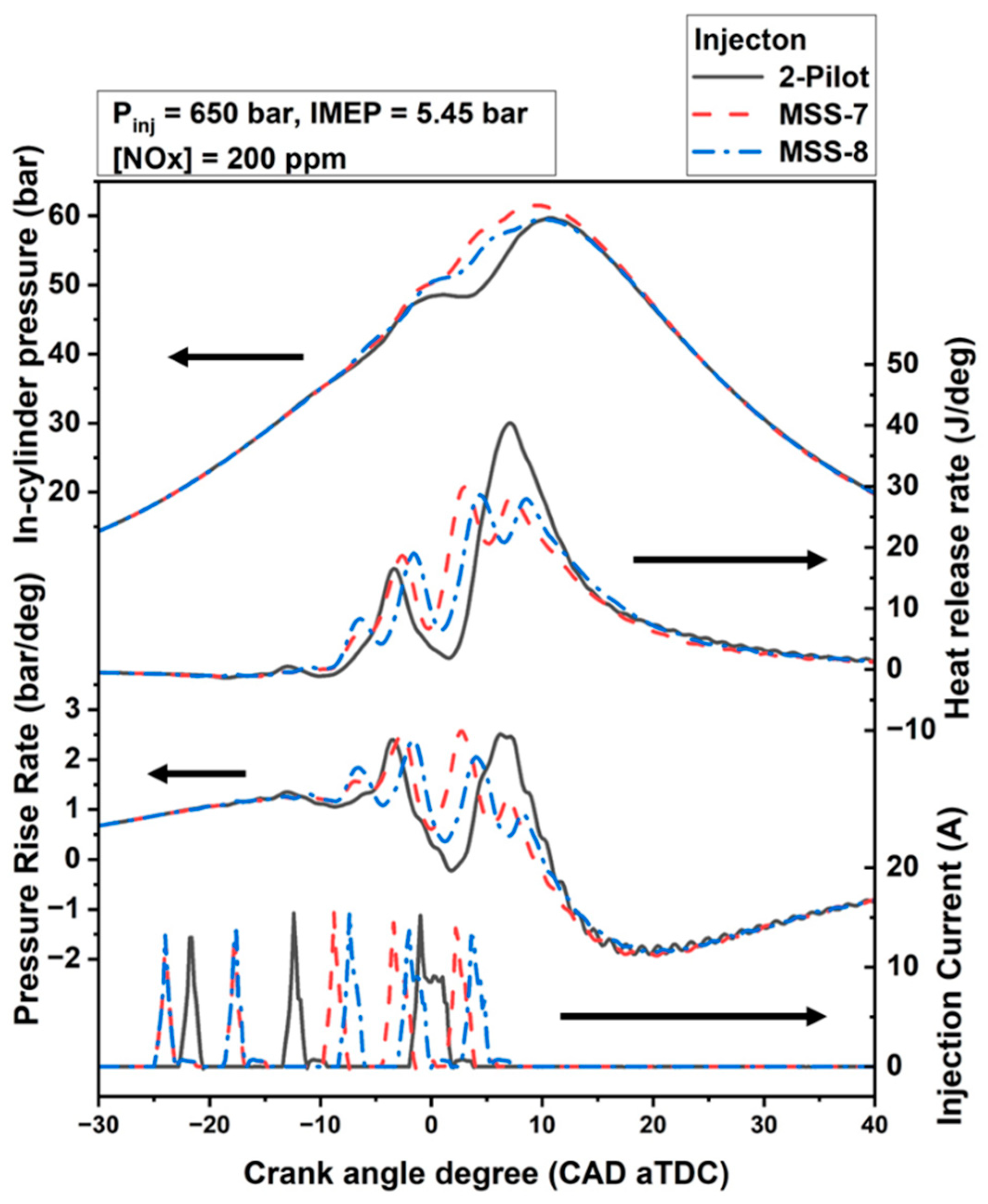
Two MSS injection strategies were compared with a reference two-pilot injection strategy. Figure 6 shows the in-cylinder pressure trace, heat release rate, pressure rise rate, and injection current results obtained for the two-pilot injection strategy and two MSS injection strategies under a 1500 rpm load and 5.35 bar IMEP without EGR. The reference injection strategy included two-pilot injections and a single-main injection as shown in the injection current profile in Figure 6. The main injection of the two-pilot injection strategy was initiated at 2 CAD BTDC. The derivatives of the MSS injection strategy were developed in terms of the combustion phase. Thus, the two MSS injection strategies were named MSS-7 and MSS-8, where the numbers indicate the crank angle position at which 50% of the heat was released (CA50). Note that MSS-8 was adjusted to have the same CA50 as the reference injection strategy, which was 8.5 CAD ATDC. Thus, the CA50 of MSS-7 was 7.5 CAD ATDC. The MPRRs of the two-pilot and MSS-7 injection strategies were on the same level.
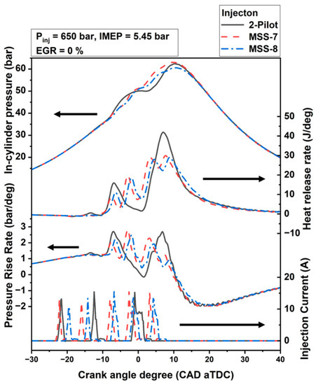
Figure 6.
In-cylinder pressure, heat release rate, pressure rise rate, and injection current results for two-pilot injection strategy and two MSS injection strategies without EGR.
For the two-pilot injection strategy, the in-cylinder pressure fluctuated in response to the separate heat releases from the pilot and main injections. In contrast, the in-cylinder pressure traces for the MSS injections were relatively smooth. Despite of the lower peak heat release rate, the MSS-7 in-cylinder pressure was higher than that of the two-pilot injection strategy because of the advanced combustion phase. The maximum in-cylinder pressure was affected not only by the heat release rate but also the combustion duration and combustion phase [10]. However, the peak in-cylinder pressure of the MSS-8 injection was lower than that of the two-pilot injection strategy, even though the CA50 values of both injection strategies were identical. Differences were apparent in the heat release rate profiles of each injection strategy. The peak heat release rate for the MSS injection strategies was lower than that of the two-pilot injection strategy because of the dispersed heat release process. That is, the injection quantity of the main injection of the two-pilot strategy constituted approximately 75% of the total injection quantity. As 75% of the fuel was injected in a single-injection event, the combustion process was concentrated, which was reflected in the heat release trace. In contrast, the injection quantity for a single-injection event in the MSS strategies constituted less than 40% of the total injection quantity as detailed in Table 5. For the MSS injection strategies, some portion of the heat release shifted to TDC, unlike the behavior for the reference two-pilot injection strategy.
The MPRR of MSS-8 was lower than that of the reference injection strategy because the pressure trace was smoother. A higher MPRR was obtained for MSS-7 because of the advanced combustion phase.
Figure 7 shows the combustion phases of the reference strategy and the two MSS injection strategies without EGR. The combustion phases from CA05 to CA90 are expressed from left to right on each bar. As noted above, the CA50 values were the same for the reference and MSS-8 injection strategies. From the figure, MSS-7 exhibited an advanced combustion phase. However, the second half of the MSS-8 combustion phase was retarded compared to the two-pilot injection strategy. Note that the fuel injection timing of the fifth injection in the MSS-8 injection was considerably later than the end of the main injection of the two-pilot injection process. As the MSS fuel supply was late, the combustion was delayed. However, compared to the 4 CAD difference between the ends of the injections, the difference in CA90 between MSS-8 and the two-pilot injection strategy was relatively small (0.6 CAD). For MSS-7, the injection end was also later than that of the two-pilot injection; however, the combustion duration was considerably shorter. These results indicate that the late-phase combustion for MSS injection was considerably faster than that for the two-pilot injection strategy.
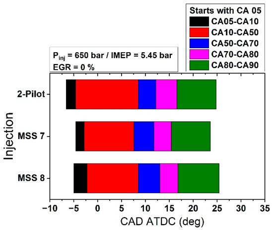
Figure 7.
Combustion phases of the two-pilot injection strategy and the two MSS injection strategies.
Figure 8 shows the in-cylinder pressure, heat release rate, pressure rise rate, and injection current results for the two-pilot injection strategy and two MSS injection strategies with EGR. The combustion for the first and second injections deteriorated due to the low-oxygen concentrations and fuel quantities. Further, the heat release from the fourth injection increased because some portion of the fuel from the preceding injections burned in addition to the newly injected fuel. As a result, the MSS-8 peak in-cylinder pressure became similar to that of the two-pilot injection strategy. The peak pressure difference between the two-pilot and MSS-7 injection strategies was more extensive than the non-EGR case. In addition, the pressure rise rate from the fourth injection was higher than in the non-EGR case. Overall, the results validate MSS injection under EGR.
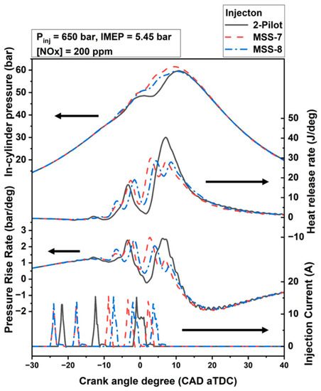
Figure 8.
In-cylinder pressure, heat release rate, pressure rise rate, and injection current results for two-pilot strategy and two MSS injection strategies with EGR.
3.3. Flame Penetration Measurement
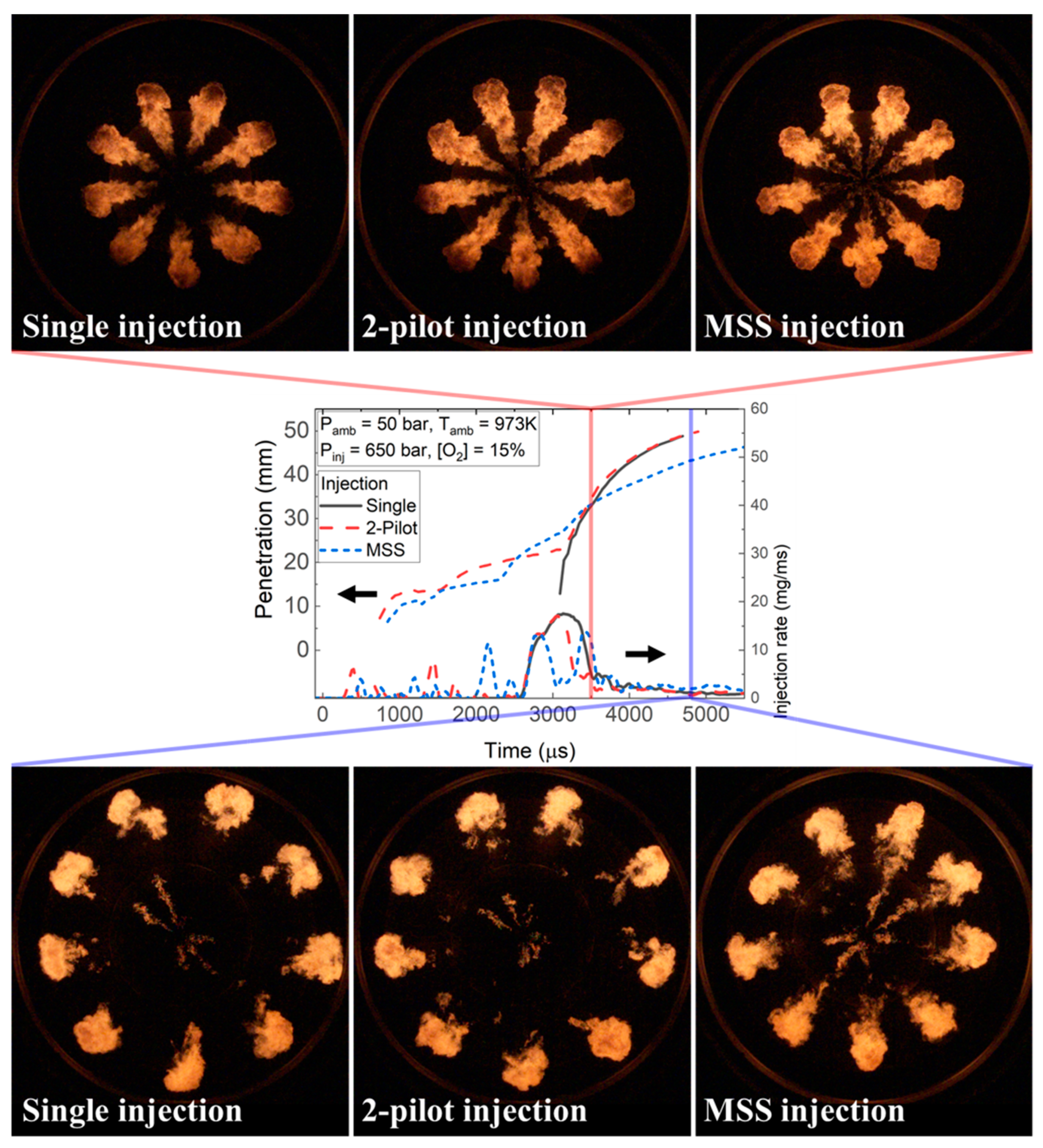
Flame penetration behaviors for single, two-pilot, and MSS injection strategies were observed in a CVCC. Note that shorter flame penetration and lower tip velocity can be interpreted as decreased interaction between the flame and piston; in that case, if the temperature difference is assumed to be unchanged, the heat transfer decreases. Figure 9 shows the flame penetration profiles of the three injection strategies. Note that the single-injection case was included for penetration comparison and that the profiles begin at the first injection signal input of the two-pilot injection strategy. In the experiment, the start timings of the single injection, main injection of the two-pilot strategy, and fourth injection of the MSS injection strategy were synchronized (recall that the fourth injection of the MSS injection strategy was the largest).
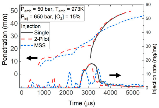
Figure 9.
Flame penetration profiles of single, two-pilot, and MSS injection strategies.
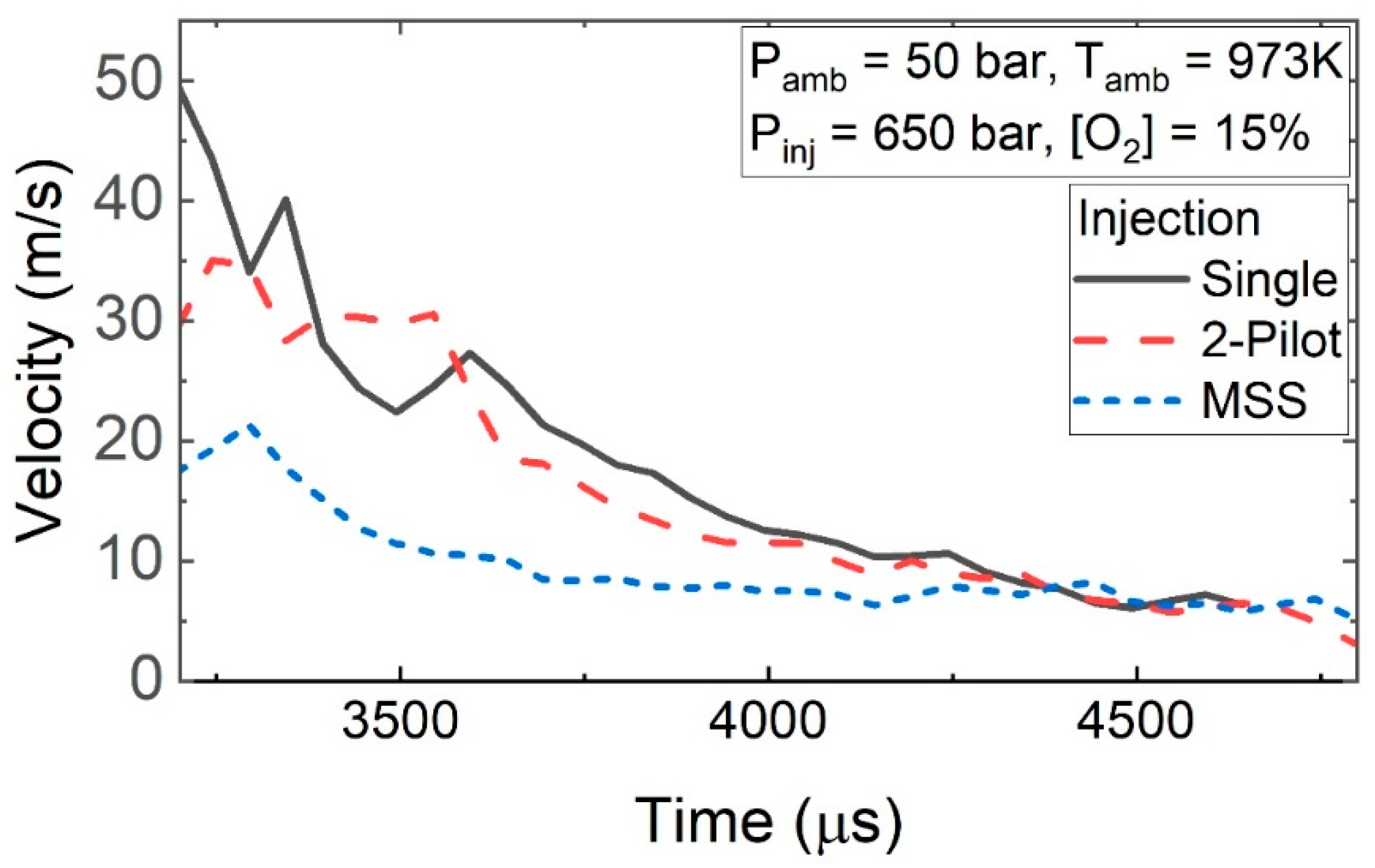
The shortest flame penetration was obtained for MSS injection, along with the lowest slope, which corresponded to the tip velocity (Figure 10). As the MSS strategy injected fuel in smaller amounts, the fuel spray momentum was not maintained to a similar degree as the spray from a single injection. Thus, the single injection, as well as the main injection of the two-pilot strategy (having a longer injection duration), maintained a higher momentum than the MSS injection. Furthermore, the single injection and the main injection of the two-pilot strategy exhibited similar flame penetration after 3000 μs.
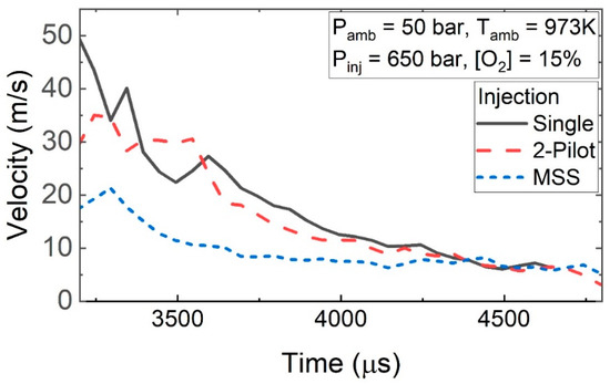
Figure 10.
Flame tip velocities of the single, two-pilot, and MSS injection strategies.
Figure 11 shows flame visualization images taken at 3500 (upper) and 4800 μs (lower), respectively. The image taken at 3500 μs following the MSS injection shows that the fifth injection penetrated the prevailing flame. Overall, the flame penetrations obtained for the three injection strategies at 3500 μs, which was 900 μs after the injection rate rise, were similar. However, at 5000 μs, the flame penetration for the MSS injection was far shorter than those of the single- and two-pilot injection strategies.
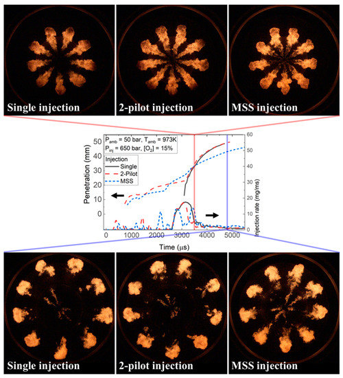
Figure 11.
Flame visualization images at (upper) 3500 and (lower) 4800 μs, based on two-pilot injection signal starts.
3.4. Efficiency and Exhaust Emissions
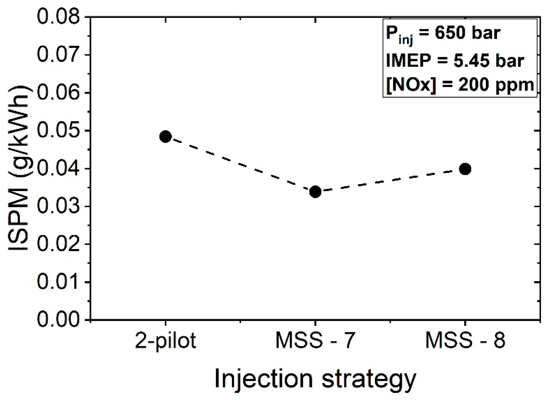
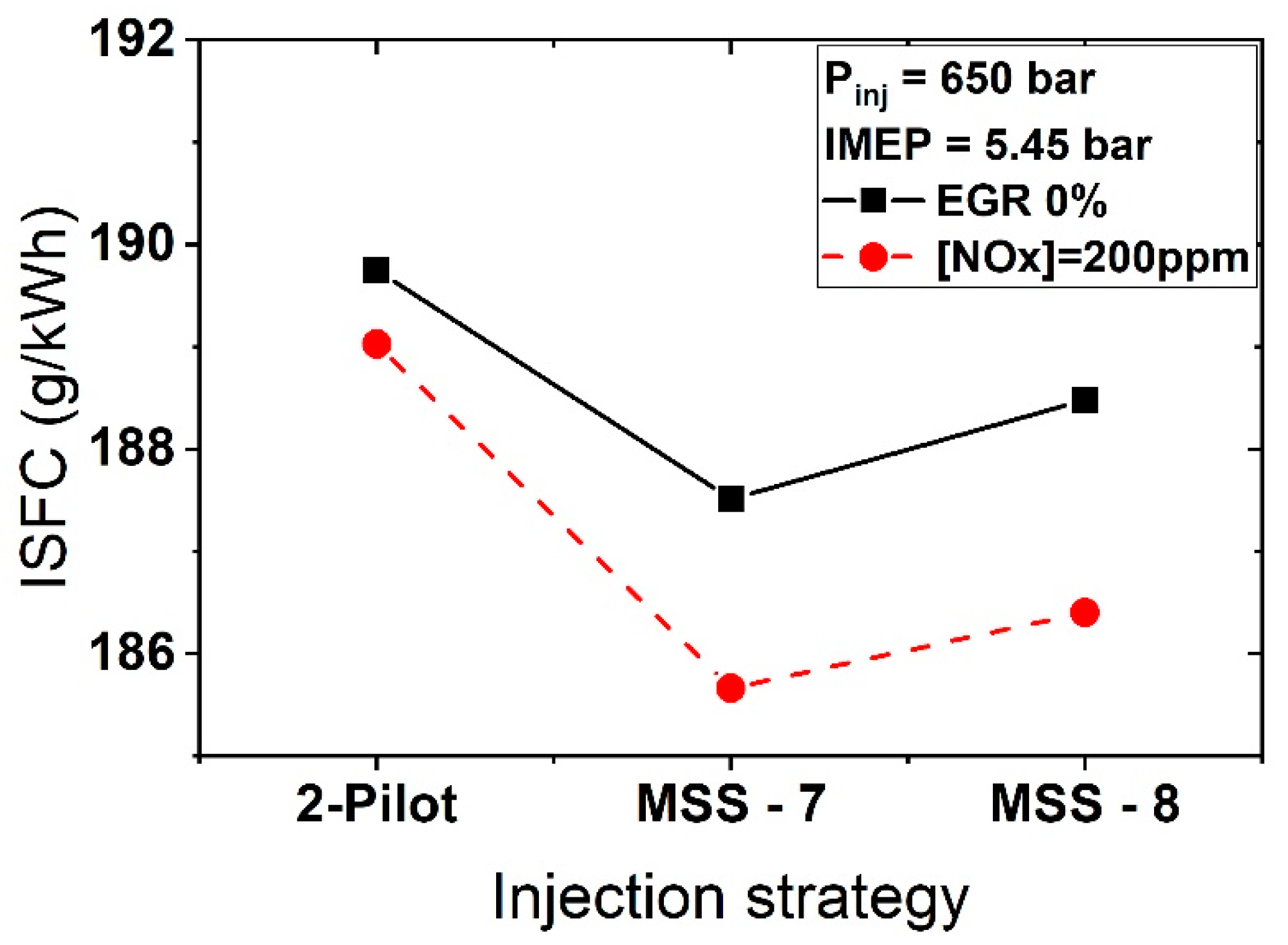
Figure 12 and Figure 13 show the exhaust emissions (i.e., the indicated specific PM (ISPM)) and indicated specific fuel combustion (ISFC), respectively, of the reference strategy and MSS-7 and MSS-8. The PM emissions for the MSS injections were lower than those of the reference injection strategy for the same NOx emissions. Compared to the reference two-pilot injection, the PM emissions of MSS-7 and MSS-8 injection were reduced by 30.0% and 17.7%, respectively, when the NOx emissions were the same with EGR adoption. This outcome can be explained as follows. The PM oxidations increased as the temperature and pressure in the cylinder increased. As shown in Figure 8, the in-cylinder pressure was higher with the MSS injections because of the shorter combustion duration. In addition, the advanced combustion duration of the MSS-7 injection resulted in higher in-cylinder pressure than the conventional injection strategy. Therefore, the oxidation of PM in MSS injections was facilitated because of the in-cylinder pressure and temperature conditions. Moreover, note that the MSS-8 strategy resulted in higher PM emissions than MSS-7 because of the retarded combustion phase. In detail, the retarded combustion phase yielded lower combustion temperature and in-cylinder pressure, which diminished the PM oxidation. Furthermore, in terms of combustion, fuel spray, and prevailing combustion overlap, the cooling effect of fuel spray decreased the oxidation of PM and increased the PM emissions. However, the MSS injections had a certain time interval; then, the swirl moved the prevailing fuel and flame in the swirl direction [4,12]. Thus, the subsequent injection supplied fuel into the relatively fresh air in the cylinder without overlapping, which decreased the PM formation. As described in Figure 8, the in-cylinder pressure was lower with the MSS-8 injection, and the temperature was also lower; then, the oxidation of the PM decreased. The ISFC trends were similar to the exhaust emission results. The MSS-7 yielded the best fuel efficiency due to the advanced combustion phase and reduced heat transfer loss. Under EGR conditions, the fuel consumption of MSS-7 and MSS-8 injection was reduced by 1.78% and 1.39%, respectively, compared to the two-pilot injection strategy. The efficiency improvement of the MSS injection was consistent with the reference [10].
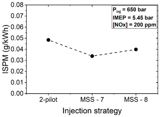
Figure 12.
Exhaust emissions of the two-pilot injection strategy and two MSS injection strategies with EGR; ISPM: indicated specific particulate matter.
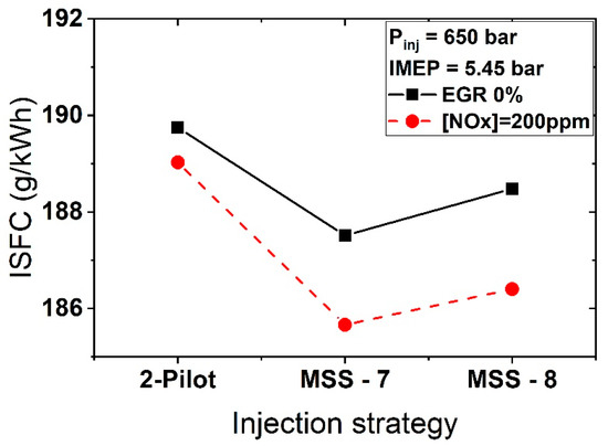
Figure 13.
Indicated specific fuel consumption (ISFC) results for the two-pilot injection strategy and the two MSS injection strategies.
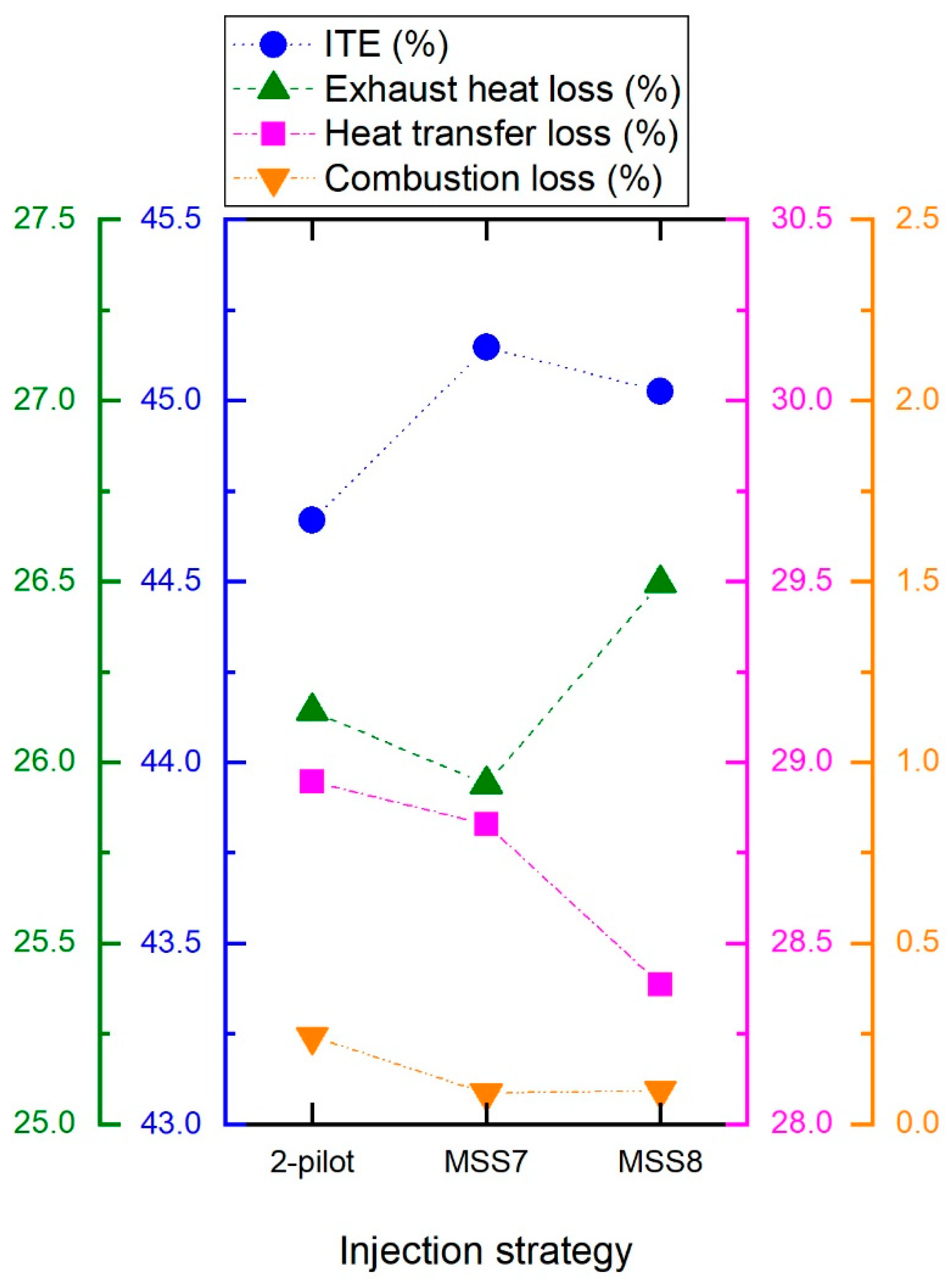
Figure 14 shows the energy balance analysis results. The indicated thermal efficiency (ITE), exhaust heat loss, heat transfer loss, and combustion loss were calculated. As for the ISFC result, MSS-7 and the two-pilot injection strategy exhibited the highest and lowest efficiencies, respectively. Compared to the two-pilot injection strategy, both the MSS injection methods exhibited lower heat transfer loss. Note that the low heat transfer loss of the MSS injection strategies was consistent with the flame penetration and tip velocity results. In particular, MSS-8 exhibited considerably lower heat transfer loss because the in-cylinder pressure was low, and the combustion phase was retarded. Further, the exhaust heat loss decreased for MSS-7 because of the advanced combustion phase. MSS-8 exhibited higher exhaust heat loss than the two-pilot injection strategy because the late combustion phase, which was from CA50 to the end of combustion of the former, was retarded although the CA50 values of both schemes were the same. Finally, the combustion loss decreased via a similar mechanism of decreased PM emissions. Overall, the MSS-7 injection strategy exhibited reduced heat transfer, exhaust heat transfer, and combustion loss compared to the two-pilot injection strategy.
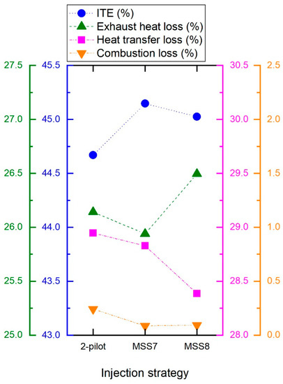
Figure 14.
Energy balance analysis of the two-pilot injection strategy and the two MSS injection strategies; ITE: indicated thermal efficiency.
4. Summary and Conclusions
Multi-stage split (MSS) injection was investigated with the aim of improving the efficiency and exhaust emission characteristics of a light-duty diesel engine under low load. The MSS injection strategy was designed to smooth the in-cylinder pressure trace while maintaining a targeted combustion phase. The main results for the MSS injection process, when compared to a reference two-pilot injection strategy, can be summarized as follows:
- The efficiency and exhaust emissions of the MSS-7 strategy (with a CA50 of 7.5 CAD ATDC) improved with no increase in the maximum pressure rise rate;
- The heat transfer, exhaust heat loss, and combustion loss of the MSS-7 injection strategy were reduced compared to the two-pilot injection strategy
- For MSS injection, the heat transfer loss decreased because of the reduced peak heat release rate, shortened flame penetration, and reduced tip velocity
- The MSS-injection flame penetration and tip velocity were lower than those of the two-pilot injection and, thus, the interaction between the flame and piston wall was reduced;
- Under EGR conditions, the fuel consumption of MSS-7 and MSS-8 injections were reduced by 1.78% and 1.39%, respectively, compared to the two-pilot injection strategy;
- For the MSS-7 injection strategy, the exhaust heat loss was lower because of the advanced combustion phase and short combustion duration;
- For the MSS-8 injection strategy, the heat transfer loss was lower than that of MSS-7; however, the retarded late combustion phase yielded increased exhaust heat loss;
- Compared to the reference two-pilot injection, the PM emissions of the MSS-7 and MSS-8 injections were reduced by 30.0% and 17.7%, respectively, when the NOx emissions were the same with EGR adoption;
- The MSS-injection PM emissions and combustion loss were lower owing to the divided combustion process along with the swirl effect. The swirl effect on divided combustion resulted in each split fuel spray penetrating the fresh air without overlapping with prevailing combustion.
In this study, MSS injection was capable of reducing fuel consumption and exhaust emissions under low-load conditions. However, the injection end was later than that of conventional two-pilot injection, which could affect post-injection processes in terms of injection timing. However, conventional post-injections tend to be implemented 8–10 CAD later than the main injection, and this timeframe does not overlap with the MSS injection timing of this study. Another consideration for MSS injection application is the potential impact on the injector durability, as MSS injection requires an increased number of valve actuation. Thus, further strategy optimization and a control model can be considered in future investigations, especially in the context of higher load conditions. As the load and speed condition increases, the required injection quantity will be increased, and the time window for injection will be narrower. Therefore, the performance of fuel injection equipment would be necessary for maintaining the effect of MSS injection. At higher injection pressure, the injection rate increased, and the injection duration decreased. However, even if MSS injection at a higher load had a negative effect, the MSS injection strategy can be adopted for low-load conditions. Modern electrically controlled engines can apply various injection strategies for each load condition without significant additional cost. Finally, note that the MSS injections considered in this study were implemented with a solenoid injector, which has a longer required dwell time between injections than a piezo-actuated injector. Thus, further strategy optimization can be performed with a piezo-actuated injector, especially under higher speed and load conditions. This is because the required injection quantity is large, and the time window for supplying fuel to the cylinder is shortened under higher speed and load conditions. Overall, the findings of this study indicate the feasibility of MSS injection for a light-duty diesel engine in the context of both improved efficiency and reduced emissions.
Author Contributions
Conceptualization, S.K. and C.B.; methodology, S.K. and S.L.; investigation, S.K. and S.L.; writing—original draft preparation, S.K.; writing—review and editing, S.L. and C.B.; visualization, S.K.; supervision, C.B.; project administration, C.B.; funding acquisition, C.B. All authors have read and agreed to the published version of the manuscript.
Funding
This work was supported by the “Competency Development Program for Industry Specialists” of the Korean Ministry of Trade, Industry, and Energy (MOTIE), operated by the Korea Institute for Advancement of Technology (KIAT) (grant number: P0017120, HRD Program to Foster R&D Specialist Parts for Eco-Friendly Vehicles (xEVs)).
Conflicts of Interest
The authors declare no conflict of interest.
References
- Schindler, K.P. Why Do We Need the Diesel? SAE Technical Paper 972684; SAE International: Warrendale, PA, USA, 1997. [Google Scholar] [CrossRef]
- Mohankumar, S.; Senthilkumar, P. Particulate matter formation and its control methodologies for diesel engine: A comprehensive review. Renew. Sustain. Energy Rev. 2017, 80, 1227–1238. [Google Scholar] [CrossRef]
- Yusuf, A.A.; Inambao, F.L.; Ampah, J.D. Evaluation of biodiesel on speciated PM2.5, organic compound, ultrafine particle and gaseous emissions from a low-speed EPA Tier II marine diesel engine coupled with DPF, DEP and SCR filter at various loads. Energy 2022, 239, 121837. [Google Scholar] [CrossRef]
- Fayad, M.A. Effect of fuel injection strategy on combustion performance and NOx/smoke trade-off under a range of operating conditions for a heavy-duty DI diesel engine. SN Appl. Sci. 2019, 1, 1–10. [Google Scholar] [CrossRef] [Green Version]
- Fayad, M.A.; AL-Ogaidi, B.R.; Abood, M.K.; AL-Salihi, H.A. Influence of post-injection strategies and CeO2 nanoparticles additives in the C30D blends and diesel on engine performance, NOX emissions, and PM characteristics in diesel engine. Part. Sci. Technol. 2021, 1–14. [Google Scholar] [CrossRef]
- Hotta, Y.; Inayoshi, M.; Nakakita, K.; Fujiwara, K.; Sakata, I. Achieving Lower Exhaust Emissions and Better Performance in An HSDI Diesel Engine with Multiple Injection; SAE Technical Paper 2005-01-0928; SAE International: Warrendale, PA, USA, 2005. [Google Scholar] [CrossRef]
- Zeh, D.; Hammer, J.; Uhr, C.; Rückle, M.; Rettich, A.; Grota, B.; Stöcklein, W.; Gerhardt, J.; Naber, D.; Raff, M. Bosch Diesel Injection Technology—Response for Every Vehicle Class Production. In Proceedings of the 23th Aachen Colloquium Automobile and Engine Technology, Aachen, Germany, 6–8 October 2014; pp. 757–772. [Google Scholar]
- Jörg, C.; Zubel, M.; Neumann, D.; Heufer, A.; Schaub, J.; Weber, J.; Herrmann, O. Digital Combustion Rate Shaping Control as a Tool to Identify Modern Fuel Injection Strategies. In Proceedings of the 26th Aachen Colloquium Automobile and Engine Technology, Aachen, Germany, 9–11 October 2017; pp. 535–564. [Google Scholar]
- Busch, S.; Zha, K.; Miles, P.C. Investigations of closely coupled pilot and main injections as a means to reduce combustion noise in a small-bore direct injection Diesel engine. Int. J. Engine Res. 2015, 16, 13–22. [Google Scholar] [CrossRef]
- Shibata, G.; Ogawa, H.; Amanuma, Y.; Okamoto, Y. Optimization of multiple heat releases in pre-mixed diesel engine combustion for high thermal efficiency and low combustion noise by a genetic-based algorithm method. Int. J. Engine Res. 2019, 20, 540–554. [Google Scholar] [CrossRef] [Green Version]
- Shibata, G.; Yamamoto, K.; Saito, M.; Inoue, Y.; Amanuma, Y.; Kobashi, Y. Optimization of combustion noise and thermal efficiency in diesel engines over a wide speed and load operational range. Int. J. Engine Res. 2020, 21, 698–712. [Google Scholar] [CrossRef]
- Denny, M.; Holst, F.; Helmantel, A.; Persson, H.; Tunestål, P.; Andersson, Ö. Impact of closely-coupled triple-pilot and conventional double-pilot injection strategies in a LD diesel engine. Fuel 2019, 246, 141–148. [Google Scholar] [CrossRef]
- Denny, M.; Matamis, A.; Wang, Z.; Persson, H.; Tunestal, P.; Richter, M.; Andersson, A.I. Optical Investigation on the Combustion Process Differences between Double-Pilot and Closely-Coupled Triple-Pilot Injection Strategies in a LD Diesel Engine; SAE Technical Paper 2019-01-0022; SAE International: Warrendale, PA, USA, 2019. [Google Scholar] [CrossRef]
- Denny, M.; Matamis, A.; Persson, H.; Richter, M.; Andersson, Ö. Interaction between Fuel Jets and Prevailing Combustion During Closely-Coupled Injections in an Optical LD Diesel Engine; SAE Technical Paper 2019-01-0551; SAE International: Warrendale, PA, USA, 2019. [Google Scholar] [CrossRef]
- Ewphun, P.P.; Otake, M.; Nagasawa, T.; Kosaka, H.; Sato, S. Investigation on effect of offset orifice nozzle under multi pulse ultrahigh pressure injection and PPC combustion conditions. Int. J. Automot. Eng. 2020, 11, 1–8. [Google Scholar] [CrossRef] [Green Version]
- Ewphun, P.P.; Nagasawa, T.; Kosaka, H.; Sato, S. Investigation on Premixed Charge Compression Ignition Combustion Control Using Multi Pulse Ultrahigh Pressure Injection; SAE Technical Paper 2019-01-1155; SAE International: Warrendale, PA, USA, 2019. [Google Scholar] [CrossRef]
- Yang, K.; Nishida, K.; Yamakawa, H. Effect of split injection ratio on combustion process of diesel spray into two-dimensional piston cavity. Fuel 2020, 260, 116316. [Google Scholar] [CrossRef]
- Bosch, W. The Fuel Rate Indicator: A New Measuring Instrument for Display of the Characteristics of Individual Injection; SAE Technical Paper 660749; SAE International: Warrendale, PA, USA, 1966; Volume 75, pp. 641–662. [Google Scholar] [CrossRef]
- Bower, G.R.; Foster, D.E. A Comparison of the Bosch and Zuech Rate of Injection Meters; SAE Technical Paper 910724; SAE International: Warrendale, PA, USA, 1991. [Google Scholar] [CrossRef] [Green Version]
- Hwang, J.; Bae, C.; Gupta, T. Application of waste cooking oil (WCO) biodiesel in a compression ignition engine. Fuel 2016, 176, 20–31. [Google Scholar] [CrossRef]
- Busch, S.; Perini, F. Progress toward understanding vortex generation in stepped-lip diesel engine combustion chambers. Results Eng. 2019, 1, 100004. [Google Scholar] [CrossRef]
- Heywood, J.B. Internal Combustion Engine Fundamentals, 2nd ed.; McGraw-Hill Education: New York, NY, USA, 2018; Volume 26, ISBN 9781260116106. [Google Scholar]
- Zhou, F.; Fu, J.; Li, D.; Liu, J.; Lee, C.F.; Yin, Y. Experimental study on combustion, emissions and thermal balance of high compression ratio engine fueled with liquefied methane gas. Appl. Therm. Eng. 2019, 161, 114125. [Google Scholar] [CrossRef]
- NIST Chemistry WebBook. Available online: https://webbook.nist.gov/chemistry/ (accessed on 16 February 2022).
- Pickett, L.M.; Genzale, C.L.; Bruneaux, G.; Malbec, L.M.; Hermant, L.; Christiansen, C.; Schramm, J. Comparison of diesel spray combustion in different high-temperature, high-pressure facilities. SAE Int. J. Engines 2010, 3, 156–181. [Google Scholar] [CrossRef]
- ECN. Available online: http://www.sandia.gov/ecn (accessed on 16 February 2022).


Publisher’s Note: MDPI stays neutral with regard to jurisdictional claims in published maps and institutional affiliations. |
© 2022 by the authors. Licensee MDPI, Basel, Switzerland. This article is an open access article distributed under the terms and conditions of the Creative Commons Attribution (CC BY) license (https://creativecommons.org/licenses/by/4.0/).