1. Introduction
In the last decade, new challenges have arisen for the electric distribution system. The growing adoption of distributed energy resources (DERs), distributed generation (DG), and energy storage systems (ESS), alongside the widespread use of electric vehicles (EVs) and the related charging infrastructure, demand for the modernization of the current distribution network. In this scenario, the concept of Internet of Energy (IoE), or Energy Internet, has emerged and is being actively discussed in the literature as the new paradigm shift for the evolution of the current distribution system [
1,
2,
3]. The goal in the IoE scenario is reshaping the current grid into an intelligent and flexible active network, both through a radical informatization process that involves the renewal of the grid communication infrastructure and the addition of distributed monitoring points and via the implementation of advanced energy management and control functionalities to enable the safe, robust, effective, and efficient integration of intermittent sources and loads [
4,
5,
6,
7,
8]. At the very heart of this future intelligent grid is the solid-state transformer (SST), a power-electronic-based system that will replace conventional distribution transformers at strategic nodes in the network to allow the implementation of the aforementioned features, thus enabling the IoE vision [
9,
10,
11,
12]. For these reasons, the SST is drawing increasingly more attention from both industrial and academic research.
Figure 1 shows the basic conceptual structure of the SST.
The idea behind the SST is to achieve voltage conversion and galvanic isolation between two AC lines through a high-frequency transformer (HFT), while the low-frequency input and output ports are coupled to the HFT via one or more cascaded power electronic converter stages. Compared to conventional line-frequency transformers, an HFT can achieve reduced volume, weight, and cost, thus allowing for a fully modular, scalable, and compact conversion system. In addition, the presence of controlled power electronics allows the implementation of advanced and flexible control features and grid services, such as bidirectional power flow, reactive power support, voltage regulation, harmonic compensation, power factor correction, etc. Remote controllability and distributed monitoring of local variables and network status can also be obtained by SST systems with the inclusion of additional communication and IT features, which can be readily implemented due to the presence of existing real-time electronic control boards, not needed in traditional magnetic-only transformers. In this context, the implementation of intelligence together with the communication and control functionalities make the SST act in the IoE scenario much like an Energy Router (ER), as illustrated in
Figure 2. In particular, IoE power distribution architectures can be based either on a DC interface (
Figure 2a), through a Low-Voltage (LV) or Medium-Voltage (MV) bus, or an AC interface (
Figure 2b). Hybrid AC/DC distribution architectures are even feasible and require multi-port solid-state transformers (MP-SSTs) with both DC and AC ports. It is worth noticing that, beside isolated SST topologies, which constitute the lion’s share among the different configurations proposed in the literature, some direct AC-AC energy router architectures, mainly based on Modular Multilevel Converters (MMCs), have also been recently suggested. The lack of isolation between the ports can be seen as a major argument against their practical implementation; however, they represent a notable addition to the family of energy router architectures. As an ER, the SST allows plug-and-play access to the network, proper integration of DG, and the deployment of smart power dispatching and management features [
1,
8,
10,
11]. For such a purpose, the ER-SST works effectively as an active node of the distribution grid. To fully exploit its role within the modern grid, it should provide multiple ports for the integration of various local sources and loads. Early versions of SSTs proposed in the literature have been developed based on a two-port architecture [
5,
12]. However, in order to connect multiple loads and sources to these types of SST configurations, a large number of additional converters are required to properly interface with the available AC and/or DC buses provided by the SST, drastically affecting the overall system efficiency and reliability. On the contrary, the concept of MP-SST fits optimally in the IoE framework [
1]. It represents an advancement in the SST technology and enables the integration of DERs, DG and ESS through suitably isolated ports within one single adjustable, modular and compact configuration, thus minimizing the number of components involved in the power conversion and increasing both the power density and reliability of the whole system [
3,
4,
5].
As an extended version of the common two-ports SST, the MP-SST shares the same basic core structure. According to the definition of SST, all of them share the same concept of isolated AC-AC high-frequency conversion. However, several configurations of SST have been proposed and can be classified depending on the number of power conversion stages, devices technology, and application. SSTs are generally classified into single-, double-, and triple-stage architectures, as depicted in
Figure 3.
Despite the lower efficiency due to the higher number of conversion stages, the triple-stage topology is the most common among the three because of the numerous features and capabilities it can offer through its controllability. In addition, it provides two DC links that allow the direct integration of DC power sources. The triple-stage SST topology based on the dual active bridge (DAB) converter for the isolation stage has been recognized as the potential best candidate for the implementation of such a converter [
13,
14]. In such an architecture, the converter building blocks can be connected either in series or in parallel to achieve the desired high-voltage and/or high-current ratings [
5,
12]. As an example, in high-voltage applications, the input and output conversion stages usually consist of cascaded multi-level configurations based on either the Cascaded H-Bridge (CHB) converter or the MMC [
5,
12]. Recent advances in high-voltage power electronic semiconductor technology have made the two-level conversion approach possible, consequently avoiding the use of cascaded converters [
5,
15] but multi-level converters are still the preferred solution in most applications.
This review article aims at providing a detailed overview of the MP-SST topologies that have been proposed in the literature so far and that represent suitable candidates for the operation as active nodes in the future IoE scenario. The major contribution of this paper consists in highlighting the features, benefits, and drawbacks of MP-SSTs, also focusing on their practical application and on the implementation issues of such complex topologies. Furthermore, two of the MP-SST topologies described in the next section will be considered in detail as case studies and further discussed in the paper. This paper is presented as follows. In
Section 2, a review on MP-SST is presented with regards to the medium-voltage and low-voltage distribution systems and the different power conversion topologies are thoroughly analyzed and compared. Technical regulations for connecting SST topologies to the electrical distribution grid are discussed in
Section 3. In
Section 4, the case study of a multi-port DAB converter for the integration of EV charging stations is analyzed in detail including simulation as well as experimental tests. A three-port multi-level SST based on the CHB converter is presented in
Section 5. Finally, conclusions are drawn in
Section 6.
2. Multi-Port Solid-State Transformer Topologies
In recent years, MP-SSTs have been introduced in different industrial applications, including railway electric traction, EV chargers and vehicle-to-grid technology, distributed generation, and DC power distribution, among others. Much research and many innovative works have been presented in the literature concerning these topologies. As an extension of the standard two-port SST, the MP-SST also provides isolation between its input and output sides, namely the Medium-Voltage (MV) side and the Low-Voltage (LV) side. However, isolation may not be guaranteed between all LV side ports, depending on the chosen MP-SST topology. In the literature, most of the proposed MP-SSTs belong to either the three- or four-port topologies. SST with more than four ports are intrinsically quite complex systems that have only been introduced recently; thus, laboratory prototypes are still hard to find. Based on the level of isolation between their ports, MP-SSTs can be broadly grouped into two main categories, namely partially or fully isolated. In partially isolated topologies, the number of connected sources is larger than the number of available transformer windings. As a consequence, multiple sources are connected to a single transformer winding on the LV side sharing a common ground and, therefore, the related ports are not galvanically isolated one from each other but only from the MV side [
4]. Partially isolated solutions can provide higher efficiency with fewer components, although providing a connection to the same transformer winding to sources and loads with different voltage levels is not obvious in practice [
4]. In this case, the integration of multiple sources with the LV bus is frequently achieved through additional non-isolated DC-DC converters. When the voltage ratings of these DC-DC converters are not consistent with the LV bus voltage or galvanic isolation is required, this solution is not feasible [
2,
13]. In fully isolated MP-SSTs, each source is connected to the system through a dedicated winding of the HFT. Each converter port is then galvanically isolated from the others both on the LV and MV sides and the appropriate voltage level required by each port can be obtained by properly adjusting the transformer turn ratio.
In this section, most of the MP-SST topologies discussed in the literature so far have been analyzed and, then, classified according to their isolation capabilities and the configuration of their various conversion stages. For the clarity of reading, this section is structured as follows. First, partially isolated MP-SSTs are discussed, followed by fully isolated architectures. As stated in the introduction, non-isolated topologies can also be found in the literature and will be discussed together with other special configurations.
2.1. Partially Isolated Multi-Port Solid-State Transformer Topologies
One of the most common partially isolated MP-SST configurations reported in the literature is a three-port SST that integrates the additional ports on the LVDC links. The concept of the three-port SST arises in the framework of multiple DC sources connected to the grid, such as in the case of photovoltaic (PV) and energy storage integration. This topology enables an LVDC link for the integration of such sources. The LVDC link can be derived either by the LV port of the DC-DC stage of the SST or by a dedicated winding of the HFT, resulting in a partially isolated or a fully isolated SST, respectively. In the literature, the partially isolated topology, generally based on the DAB converter, is the most commonly used three-port SST configuration. However, its application is unfeasible when the voltage ratings of the non-isolated converters connected to the same LV bus are highly different or when isolation is required between each LV port [
2,
16,
17]. The popular FREEDM Gen-1 silicon-based SST is an example of this type of configuration [
17,
18,
19,
20,
21,
22]. The FREEDM Gen-1 SST, a project supported by the ERC Program of the National Science Foundation, consists of a 20 kVA single-phase three-port SST prototype designed to operate with a 7.2 kV primary voltage providing a 120/240 V AC port for utility applications and a 400 V DC port for DERs and DG integration. The converter topology is reported in
Figure 4. The MP-SST configuration adopted for the FREEDM converter is commonly referred to as Input-Series Output-Parallel (ISOP). It relies on a CHB converter as the input rectifier stage and on a DAB converter as the isolated DC-DC stage. The output LV ports are derived from the LVDC bus; thus, they are isolated from the MV input side but not from each other. A three-phase version of this configuration was presented in [
23] alongside with some considerations of the control system and experimental results.
The CHB converter represents a good candidate for the multi-level AC-DC stage of the SST, due to its modularity and simplicity. It can provide LVDC, LVAC, and MVAC ports, but no MVDC port can be derived due to the lack of a common DC bus. For this reason, CHB-based MP-SSTs are not suitable for hybrid AC/DC distribution systems [
24,
25]. On the contrary, MMC-based MP-SSTs inherently enable a four-port converter structure providing both MVAC and MVDC ports for the hybrid distribution system integration, in addition to the LVAC and LVDC ports typically required in utility applications. Despite its flexibility, the MMC-based MP-SST is usually a partially isolated topology due to the natural configuration of the MMC converter, which provides a direct non-isolated connection between the MVAC port and the MVDC bus.
Figure 5 shows a partially isolated four-port MMC-based SST able to provide low- and medium-voltage connections in both DC and AC. As can be observed in the figure, the MV ports are isolated from the LV ones, but not each other. In [
26], some simple three-port MMC-based SST topologies providing an isolated LVDC port are discussed. In [
24], an in-depth comparison between CHB- and MMC-based MP-SST configurations is carried out highlighting the benefits and drawbacks of both topologies. It has been shown that the advantage of the MVDC port enabled by the MMC converter is achieved at the price of a larger number of components and higher device ratings. In fact, to support the same voltage level of a CHB-based MP-SST, the MMC-based solution requires four times the number of cells in comparison to the CHB-based one. If the common MMC configuration is used, i.e., half-bridge cells, then the number of devices required by the MMC is two times the CHB. Furthermore, the MMC flexibility that allows the coupling of multiple ports leads to a considerably different amount of power that the cells and the power devices must handle compared to the CHB-based solution. This results in a higher rating of the converter devices. The authors of [
25] have discussed three basic MMC-based MP-SST configurations providing four-port connection capability. Such topologies are partially isolated, as MV ports and LV ports are not isolated each other, but galvanic isolation is provided only between MV and LV sides. The isolated DC-DC stage is provided by a DAB converter. The MMC-based MP-SST configurations differ from each other only in the interconnection of the basic building blocks. In particular, the topologies investigated in [
25] include an Input-Series Output-Series (ISOS) and an ISOP cell-to-cell connected MMCs. In a further configuration, the building blocks still employ an ISOP connection, but one of the MMCs is replaced with a different topology (e.g., a two-level or a neutral-point-clamped inverter). The authors of [
27,
28] have illustrated the MV prototype of an MMC-based four-port SSTs. Acting as an ER, the proposed 10-kVAC 750-VDC converter takes advantage of MMC flexibility to interface MV and LV grids. The discussed topology achieves galvanic isolation through HFTs and the DC-DC modules are ISOP-connected.
In [
29], an MMC-based MP-SST using an LC resonant circuit and HFT in replacement of the DAB converter has been proposed. A resonant tank is connected in parallel with each arm of the MMC, across which a medium frequency voltage is generated through a mixed-frequency modulation technique. The resonant tanks, together with the HFT, impose the isolation barrier among the MV and LV ports. The proposed configuration achieves the power flow between MV and LV side with only three conversion stages (instead of four as in standard DAB-based solutions), thus reducing the converter size and improving the system efficiency. As an optimization of such a topology, in [
30], the number of HFTs is reduced to only two by employing a shared configuration of the resonant tanks. Furthermore, the degrees of freedom and flexibility of the MMC allow for a further reduction of the number of conversion stages between the MV and LV ports as reported in [
31,
32], where only two power conversion stages are employed. The main drawbacks of these topologies are the absence of a MVDC port for hybrid AC/DC distribution systems and the requirement of H-bridge-based MMC cells to generate the high-frequency voltage waveform for the transformer windings.
Finally, in [
33] the authors have proposed an MMC-based MP-SST in which the galvanic isolation between MV and LV ports is achieved through a Quadruple Active Bridge (QAB) converter, a four-port isolated DC-DC converter featuring a multi-winding HFT. Further details about the QAB converter will be given in the next section, where a case study is discussed directly involving this topology. The QAB converter couples together three submodules of the MMC (one per phase) with the LVDC link. Such a solution, along with its dedicated control strategy, is able to achieve a better distribution of the power flow among the three phases of the MP-SST.
2.2. Fully Isolated Multi-Port Solid-State Transformer Topologies
As in the case of partially isolated architectures, also for fully isolated MP-SSTs, the most common configurations are the three- and four-port SSTs. Fully isolated versions of the three-port SST can be found in the literature based on essentially two different approaches, either by means of a three-port isolated DC-DC converter based on the Triple Active Bridge (TAB) topology, which is an extended version of the DAB converter with a three-winding transformer, or by employing other isolated DC-DC topologies together with a series or parallel connection of the MP-SST building blocks that ensures the mutual isolation of any of the ports. In the first case, the MP-SST relies on the TAB converter as the core isolating stage [
34]. A proper control system should be provided when multi-winding DC-DC converters are employed. First, since the power delivered by one bridge depends on the phase-shifts of the other two bridges, the power flow of the converter should be decoupled in order to obtain a power equation for each port independently from the others. Furthermore, as explained in [
35], when the converter ports operate at voltage levels that are highly different, large circulating currents will flow in the TAB converter, leading to important conduction losses and, in some cases, even to the loss of the soft-switching features. Thus, a control system based on both phase-shift and duty-cycle variations should be adopted for this converter to optimize dynamics and efficiency.
In case the isolation is achieved through a dedicated converter building blocks interconnection, one suitable MP-SST configuration that ensures isolation between all ports consists of an ISOS connection of the circuit building blocks and the DAB converter as the core isolation component. As an example of this configuration, one of the major converter designs known in literature is the UNIFLEX SST project, supported and promoted by the European Community under the 6th Framework Programme [
36,
37,
38,
39,
40,
41,
42,
43]. The UNIFLEX topology is depicted in
Figure 6. It consists of a three-port 300-kVA SST designed for the future electricity network with the purpose to interface two 3.3-kV AC grids with a 415-V AC grid. This configuration provides a fully modular and scalable converter. The control system of the DC-DC stage is less sophisticated compared to the TAB-based topology as it consists of the DAB converter and, thus, the power cross-coupling consideration is avoided. However, in this system, the power flow among the output ports, referred to in [
44] as Port 2 and Port 3, is not direct, since those two ports can only exchange power between them through coupling with Port 1. Another approach that does not make use of a three-winding HFT is given in [
45]. Two different configurations of an isolated SST topology based on the CHB and DAB converters are proposed to achieve a lower number of conversion stages between the ports. The proposed solutions provide better efficiency and the downsizing of the LV feeders, compared to the commonly adopted topology reported in [
17].
Regardless of the partially or fully isolation class, it is important to report that the QAB converter has also been tested as a possible feasible basic cell for a three-port SST [
46,
47]. This is because a generic
n-winding isolated DC-DC converter can be connected to less than
n different ports. In this case, any port is coupled with the others through more than one winding, since the QAB converter provides a flexible connection and can be connected either in a symmetrical or in an asymmetrical way, providing different solutions to the voltage and power level for the isolating stage of the converter.
Beside three-port SSTs, the majority of MP-SSTs are basically four-port SST converters. This topology has been introduced mainly through the development of the aforementioned QAB converter, an isolated DC-DC converter developed as an extension of the DAB converter and belonging to the Multi Active Bridge (MAB) topologies [
13,
46,
47], in which multi-winding HFT are used. As depicted in
Figure 7, it is made of four active bridges; thus, it provides a connection to four isolated sources.
The major benefit brought by the QAB converter in a multi-port architecture is the reduced number of transformer cores and modules, and thus, less encumbrance compared to a DAB-based MP-SST, while still preserving the same advantages. Furthermore, it provides modularity, scalability, high power density, and also additional degrees of freedom in the converter connection ports [
3,
13,
46,
47]. Thus, the standard fully isolated four-port SST topology, which can be found in the literature, relies on the QAB converter. The very first QAB-based four-port SST was developed in [
13], for ESS and DG integration. The paper highlights the benefits of a QAB-based MP-SST structure, providing an average model used to properly design the converter control system. In fact, as also reported in [
48] and mentioned above for the TAB converter, the power delivered by one port depends on the phase angle of the other three ports. This cross-coupling characteristic needs to be taken into account when designing the control system of the QAB converter. A linearization around a nominal operating point is needed to decouple the power equation for each port. Through this procedure, it is possible to obtain a better dynamic performance of the converter. The experimental results reported in both [
13,
48] provide a validation of the theory. The authors of [
6] pointed out that in a QAB system there are some operating modes characterized by high phase-shift values that produce large reactive currents. It was mentioned that even under light-load conditions the phase-shift control of the converter produces high circulating currents. Thus, the authors propose a new control strategy, designed as a combination of phase-shift and duty-cycle control to ensure both the power balance among the ports and the desired output voltage. In general, considering an IoE scenario with intermittent DERs, DG, and storage, [
49] suggests a Multi-Input-Multi-Output (MIMO) control scheme to meet all the operating modes discussed in the article. It is worth pointing out that the major issues with QAB-based SSTs are the complexity of the control system and the manufacturing of the multi-winding transformer. In particular, the latter has been discussed in several papers. In [
50], the operating principle of a SiC-based QAB converter for fast charging station application has been discussed, together with the design procedure of the HFT and the selection criteria of the power devices. The authors of [
51] discussed the HFT design for a QAB-based SST for microgrids, considering one port of the converter as having a MV rating. Through Finite Element Analysis, the HFT have shown 99.7% efficiency; some preliminary laboratory results are also given. To avoid the use of a multi-winding HFT, the authors of [
2] proposed a megawatt-level high-frequency bus-based four-port SST, which relies on the so-called Modular-MAB (M-MAB). The proposed topology presents mutual isolation, mutual independence among different ports and a modular structure. Despite its benefits, the topology has as a drawback that the control strategy is complex due to the high-frequency bus, which may easily propagate a disturbance occurring at one of the ports to the others.
MMC-based, fully isolated SST architectures have also been proposed in the literature. As discussed in the previous subsection, the MMC structure is inherently a partially isolated topology; however, in some cases, the MVDC port is used as a grid or load interface and the MVAC one is not directly accessible since it is employed as a coupling interface with other converters. This is for example the case of isolated multi-port DC-DC converters acting as DC hub. Nowadays, the High Voltage Direct Current (HVDC) technology is becoming more popular. As for traditional AC lines, even for DC distribution systems, there is a need for an intelligent and flexible multi-port DC-DC converter that interconnects and manages DC sources and loads acting as a DC energy router. The MMC converter fits optimally as a DC-AC interface that provides an AC-link, through which an HFT is connected to achieve isolation between all the DC ports, as pointed out in [
52]. In this paper, the authors have presented a review of different topologies suitable for DC hub converter applications. The MMC-based one has been identified as the most promising and a three-port MMC-based DC hub is considered as a case study. In [
53], two parallel-connected MMC have been proposed to build a three-port DC hub; this solution, known as bifurcate MMC, avoids the use of a multi-winding transformer. The authors of [
54] investigated the MMC-based MP DC-DC converter as a truly modular HV DC-DC converter, built with multiple submodules that can be controlled individually through decentralized controllers, thus allowing the easy reconfiguration of the power converter circuit for different DC applications. Finally, in [
55] a fully isolated four-MV-port SST based on MMC and MAB converters was proposed for the HVAC distribution architecture. Such a solution acts as an ER in a HVAC distribution system scenario and provides isolation between all the AC ports. It is worth noticing that a MVDC port could be derived from each AC interface; however, in this case, the topology becomes a partially isolated one, since there is no isolation between the DC and the respective AC ports.
2.3. Other Topologies
As discussed previously, the most common MP-SST configurations are three- or four-port based, while generic
n-port topologies, with
n greater than four, are uncommon due to complexity in design and control. A
n-port SST based on the MAB architecture comprises
n full bridges coupled together through a
n-winding HFT. It enables the isolated interconnection of multiple sources and loads at different voltage levels through the adjustment of the HFT turn ratios, achieving a high-power density conversion in a single system [
13]. The limitation on the number of ports of a MP-SST is usually dictated, as for the QAB converter, by the complexity of the control system and by the HFT magnetic core design [
2,
13]. Beside the ideal design based on a
n-winding HFT, the
n-port SST can be built through the proper interconnection of the isolated DC-DC converter outputs, regardless of the partially or fully isolation approach, as stated for the other MP-SST topologies. To the authors’ best knowledge, in the literature, only [
1] presented
n-port SST, which is a nine-port ER in a LV smart grid scenario. In the article, the authors highlighted two converter variants and provided the circuit parameter design and the adopted control strategy, which is based on an energy management system. Experimental results on the two Multiple Energy Router prototypes validated the analysis. Beyond that, in [
56], further direct AC-AC MMC-based topologies that fit quite well as ERs are discussed. In particular, the Hexagonal MMC and the Ring-Star MMC provide connection to a multiple number of ports and phases realizing a modular active node converter. However, these topologies are direct AC-AC converters, and therefore, they do not provide any kind of galvanic isolation between ports; thus, the basic concept beyond the SST decays. Still, those topologies are quite interesting and deserves further investigation as ER concept. The comparison based on the characteristics and design criteria of the most relevant SST topologies previously analyzed is shown in
Table 1.
3. Integration into the Electricity Grid
Clean energy transition is one of the most popular current topics worldwide. Every nation has to face this challenge, while also enhancing the security, flexibility, and efficiency of the electricity grid, increasingly avoiding the use of polluting raw materials. These points distinguish the just-presented MP-SST that could, therefore, play a key role in the near future. To understand whether this solution is really feasible, it is necessary to assess if it can be included in the framework of electricity grid management.
The decarbonization argument started in the last decades of the 20th century (UN Conference on the Human Environment in Stockholm in 1972), but the real process of change began only with the Kyoto Protocol of 1997 that came into force in 2005 [
57]. Since then, several measures have been applied all over the world. Referring in particular to the European Union (EU), the latest update in the energy policy framework consists in the
Clean Energy Package written in 2019, which includes eight legislative acts as well as other initiatives that established the basis for the Directive and Regulation of the future European electricity market [
58]. The
Regulation (EU) 2019/943 [
59] aims to “set the basis for an efficient achievement of the objectives of the Energy Union and in particular the climate and energy framework for 2030 by enabling market signals to be delivered for increased efficiency, higher share of renewable energy sources, security of supply, flexibility, sustainability, decarbonization and innovation” (Article 1). Moreover, it aspires to “harmonize the rules for cross-border exchanges in electricity”, where “all market participants shall be responsible for the imbalances they cause in the system” (Article 5), and to “accommodate the increasing share of variable generation, increased demand responsiveness and the advent of new technologies” (Article 6). It follows that the EU is strongly promoting research, innovation, and competitiveness in order to modernize the nationally organized electricity market and to look forward to cooperation among markets of the EU Member States. This point is further confirmed by the
Directive (EU) 2019/944 [
60] that “rewards flexibility and innovation” by focusing on topics as smart metering, storages, and E-mobility. Furthermore, to create a “truly integrated competitive, consumer-centered, flexible, fair and transparent electricity markets in the Union”, it establishes “common rules for the generation, transmission, distribution, energy storage and supply of electricity, together with consumer protection provisions” (Article 1). Hence, it requires to “regulatory authorities and Transmission System Operators (TSOs) to cooperate towards the creation of a fully interconnected internal market for electricity that increases the integration of electricity from renewable sources, free competition and security of supply” (Article 1).
Each EU Member State has to observe these new laws, but it can enjoy independence with regard to effective decision-making rights to operate, maintain, or develop the grid. Because of this, the Italian case is taken as reference and its solutions are compared with the EU directives.
Terna, the Italian TSO, is actively working on this topic. Two pilot projects were presented and accepted by the Italian supervisory authority
ARERA (Autorità di Regolazione per Energia Reti e Ambiente). Both enable the creation of the community energy (Article 16), thanks to the active participation in the market of all customer groups (industrial, commercial, and households) that can “make full use of the advantages of aggregation of production and supply over larger regions and benefit from cross-border competition” as required by [
60].
Terna refers to the companies managing these aggregations as Balance Service Providers (BSPs). Moreover,
Terna ensures that, “when procuring ancillary services, market participants engaged in the aggregation of demand response are treated in a non-discriminatory manner alongside producers on the basis of their technical capabilities” (Article 17). These two projects can be summarized as follows:
Fast reserve [
61]: to face the reduction of grid inertia that has occurred with the widespread use of renewable energies, this service aims to improve the dynamic response of the grid during the first moments of frequency transients. Power plants, storages, and BSPs that participate in this project have to guarantee the activation of a pre-defined amount of power reserve (lower than 25 MW but higher than 5 MW) in less than one second, with a response start-up time lower than 300 milliseconds and that can be sustained for at most 15 min each 2 h. Those that are characterized by a medium or low voltage connection must meet the requirements of CEI 0-21 and CEI 0-16 standards. Further technical requirements are defined in Annex 3 of Fast reserve documentation.
UVAM [
62]: this service brings in new suppliers to the energy dispatch if they can create an aggregation that includes storages, generation, and/or consumption units in a limited geographical area (defined in Annex 6). In fact, UVAM (Unità Virtuali Abilitate Miste) stands for mixed virtual units that have been enabled by
Terna to participate to the Ancillary Services Market. UVAM power reserve should be higher than 1 MW (Annex 2) and it should be guaranteed for at least 120 or 480 min, depending on the type of service that they offer.
Since Terna requires the installation of specific smart meters to take part to these projects, the higher the number of companies participating, the greater the support for the creation of a Smart Grid.
Simultaneously with these changes, the Distribution System Operators (DSOs), coordinated by
ARERA, are embracing the possibilities and responsibilities conferred by [
60]. DSOs, subject to fair compensation, shall:
“Cooperate with citizen energy communities to facilitate electricity transfers” (Article 16) as a “neutral market facilitator”. Hence, they have to integrate BSPs work in the electricity grid management.
“Cooperate with TSOs for the effective participation of market participants connected to their grid in retail, wholesale and balancing markets” (Article 31).
“Procure the non-frequency ancillary services needed for its system” (Article 31).
Operate, maintain, and develop “under economic conditions a secure, reliable and efficient electricity distribution system in its area with due regard for the environment and energy efficiency” (Article 31).
Hence, DSOs have to actively participate to local ancillary services for both coordination and procurement roles in order to respect the system technical limits of current and voltage: they do not participate to frequency regulation and energy balancing, but they can solve problems related to energy congestion, voltage regulation, and power restoration in case of emergency. To achieve these results, DSOs can perform changes in the grid management and/or enhance the infrastructures. Moreover, [
60] foresaw that “Member States shall provide the necessary regulatory framework to allow and provide incentives to DSOs to procure flexibility services” and DSOs “shall provide transparency on the medium and long-term flexibility services needed for the next five-to-ten years, with particular emphasis on the main distribution infrastructure which is required in order to connect new generation capacity and new loads, including recharging points for electric vehicles.” (Article 32).
ARERA officially acknowledged the role of DSOs in the
Consultation Document 322/2019 [
63] and it, consequently, set up pilot projects with the
Deliberation 352/2021 [
64]. Both documents are more focused on the management modernization of electricity market and energy dispatch, but
ARERA recognizes the responsibility of DSOs concerning the “procurement of products and services that are necessary for an efficient reliable safe operation of the distribution network” ([
63] Section III.5.2).
ARERA highlighted in [
64] that it is necessary to identify “the technological solutions that can be used” for the already-mentioned purposes and “to evaluate the existence of a potential market and its degree of competitiveness”. It also suggests endorsing “open modular and non-proprietary solutions that allow the provision of service and remote monitoring of the services”.
Since the interaction between DSOs and TSO plays a key role in the network future development, its topology is currently under study: [
63] summarizes the first results obtained from the project
SmartNet, supported by the European program
Horizon 2020, but no final actions were officially approved. It follows that further work shall be done in this regard.
Therefore, MP-SST topologies meet the requirements of the
Clean Energy Package thanks to their flexibility and efficiency that allow: a higher exploitation of renewable energy sources, storages, and E-mobility with a limited power loss; a simplified interconnection of the community energy; the use of new systems that ensure the participation to ancillary services, which DSOs and TSO could rely on; a widespread installation of smart meters, which are necessary for multi-port operation; the improvements related to the hosting capability and the resiliency of the lines; and a research stimulus and modernization of grid management that makes BSPs and DSOs take advantage of available European funds. They consequently have all the technical requirements to be included in the framework of the electricity grid management in both Europe and Italy. In order to understand whether the multi-port exploitation is also economically viable, a feasibility study should be done for specific cases. The authors of [
65] performed such a study while evaluating the usage of one multi-port topology, defined as Active Node, to link two asynchronous MV lines and to permit a real-time active and reactive power flow control by the Italian DSO
Areti. The power electronics interfaces, simulated as if installed in a strategic position of the grid with
DigSilent PowerFactory software and with a 1-year measurement campaign data, enabled the direct routing of electricity, avoiding its worthless injection in HV networks (reduction of the reverse energy flow around 49.6% and 92% in the two presented scenarios) as well as providing ancillary services without requiring any procurement with Distributed Generation owners. Such benefits were obtained with a Return On Investment (ROI) in the range of 2.4 to 11 years, which results in a feasible investment.
4. Case of Study
4.1. Multi-Port Bidirectional Dual Active Bridge Converter for EVs Fast Charging
Fast-charging stations now plays a key role in the spread of EVs and Plug-in Hybrid Electric Vehicles (PHEVs) today [
66]. One of the main problems in charging EVs is the charging time, which can change according to the size of the battery [
67]. Furthermore, the increase in EVs produces an increase in electricity demand, which requires a strengthening of the existing local grid. Therefore, the goal to be achieved is to have a charging station with a fast charging time and a low impact on the electricity grid. A further challenge associated with the design of EV chargers is to have a galvanic isolation system with high power density and high efficiency. The aforementioned objectives can be achieved by increasing the switching frequency of the power conversion system, allowing the use of the HFT. However, the increase in the switching frequency translates into an increase in switching losses in power semiconductors. Thus, methods and resonant circuits are widely used to increase the switching frequency [
67]. Several researchers are working worldwide on the development of innovative charging station able to provide galvanic isolation, reducing the charging time and, at the same time, exploit renewable resources without modifying the existing electrical grid [
68,
69,
70,
71,
72].
One of the promising conversion topologies to do this is the multi-port DAB converter [
73]. This topology makes use of multiple full-bridges (FBs) connected between the windings of the HFT, as shown in
Figure 8.
The FB connected between the energy storage (FB 1) and the windings can operate both as a source—to help the photovoltaic system to provide the necessary power—and as a load, recharging itself when necessary. The FB of port 4 (FB 4) is able to manage the photovoltaic system, while the FBs of port 2 (FB 2) and port 3 (FB 3) are connected to loads, i.e., electric vehicles. The charging station is able to provide 100 kW with a voltage range included between 600 V and 960 V. For voltages lower than 600 V, lower powers are transferred in order to limit the current in both power semiconductors and HFT. The main benefit of this charging station is its modular feature, as it is very simple to extend both the number of sources (also using the electrical grid) and the number of EVs to be recharged. Furthermore, the charging station operates in island mode; thus, the electrical grid infrastructure does not need changes, it is only used to recharge the ESS at the FB of port 1. Another advantage of such power conversion system is the possibility of using fast power semiconductors, such as Silicon Carbide (SiC) power switches, which allow to reduce the power losses. Additionally, different modulation strategy can be used with the aim of increasing the performance of the power conversion.
4.2. Operation Mode of the Multi-Port DAB Converter
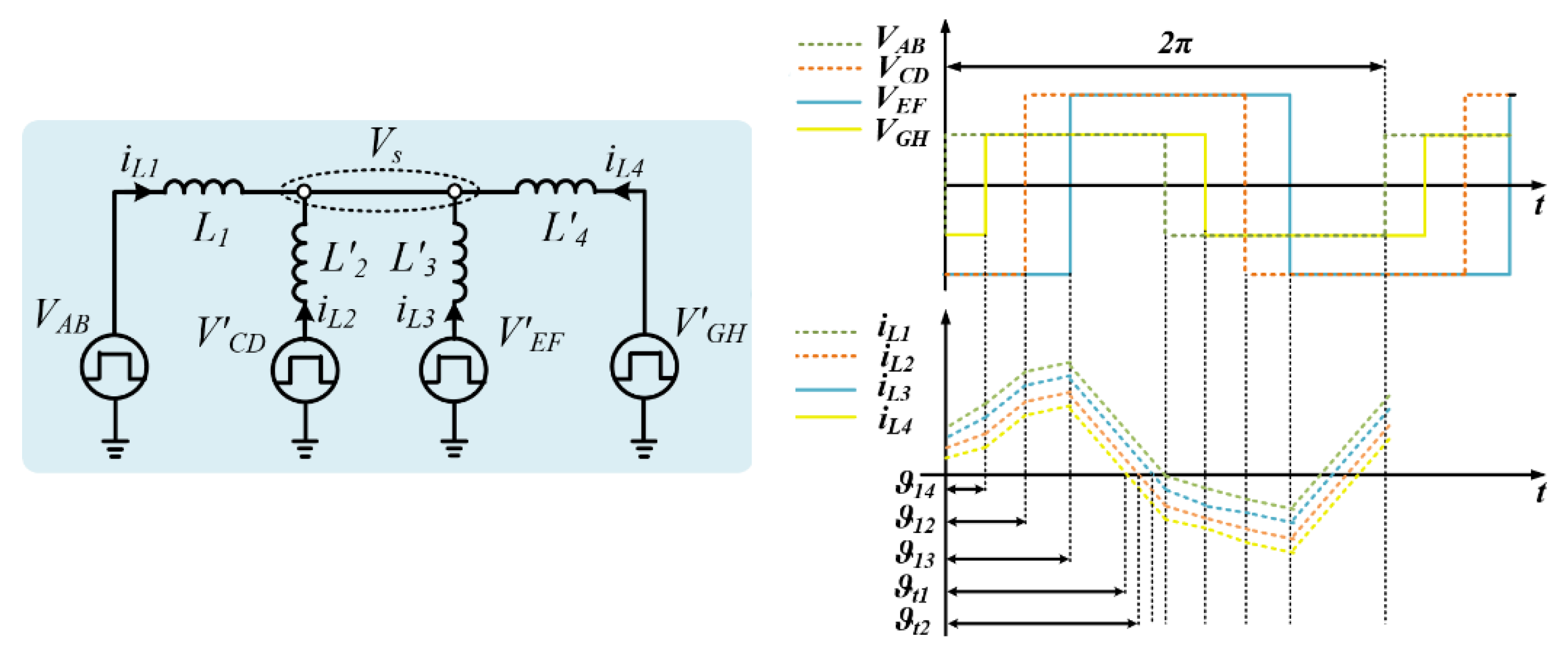
The power conversion system is analyzed according to the equivalent model shown in
Figure 9, where each FB is highlighted as a rectangular voltage source (
VAB,
V′CD,
V′EF,
V′GH).
The equivalent parameters are calculated in Equation (1), where L′2, L′3, and L′4 are the equivalent leakage inductances at the primary side of the transformer, V′CD, V′EF, and V′GH are the equivalent voltages at the primary side of the transformer, and N1, N2, N3, and N4 are the number of turns of the windings in the relative ports 1, 2, 3, and 4:
Applying the nodal analysis, the voltage across the common node vs. can be obtained as in Equation (2):
The Single-Phase Shift (SPS) modulation technique is used to control the conversion system [
74]. Using this technique, the rectangular voltages
V′CD,
V′EF, and
V′GH are shifted, lagging with respect to the voltage
VAB, by the phase shifts
ϑ12,
ϑ13, and
ϑ14, respectively. By controlling the phase shifts of the FBs, it is possible to change the transfer power. According to the phase shifts
ϑ12,
ϑ13, and
ϑ14, two operating modes of the converter are identified. The converter operates in a boost mode when the phase shifts
ϑ12,
ϑ13, and
ϑ14 are positive, while operating in a buck mode when the phase shifts
ϑ12,
ϑ13, and
ϑ14 is negative. In order to obtain the relation of the power in each operating interval as a function of circuit parameters, Equation (2) is evaluated in each time interval, assuming
VAB = V′GH,
V′CD =
V′EF,
V′CD > VA, and
N1 =
N2 =
N3 =
N4.
Figure 10 shows different operating intervals of the converter, where the current paths are highlighted in red. The leakage inductance currents for different intervals are written in
Table 2, where
V′z, with z ∈ {AB, CD, EF, GH}, is the voltage across the winding and vs. is the voltage across the common node. The subscript x ∈ {1, 2, 3, 4} indicates the current flowing in the leakage inductance of each FB. Starting from the average current written in Equation (3), Equation (4) shows the relationship between the power at port-
i and port-
j, where
Vi is the voltage across the port-i,
VTHij is the Thevenin equivalent voltage between the port
i and port
j,
Lij =
Li +
LTHij is the equivalent inductance between the ports,
LTHij is the Thevenin equivalent inductance of the circuit between the port
i and port
j,
fsw is the switching frequency, and
ϑij is the phase shift between the two ports. The equivalent voltage
VTHij and inductance
Lij are defined as in (5), with
k = 1, 2, 3, 4.
Thus, it is possible to define the equivalent model of the multi-port DAB converter by neglecting the magnetizing inductances, as illustrated in
Figure 11. Through this circuit, it is possible to evaluate the total power provided by a single port, according to all the characteristics of the system.
For instance, assuming that two sources are connected to FB1 and FB4, while two loads are connected to FB2 and FB3, the power provided by a single port is written in Equation (6), where Pij is the power transferred from port i to port j. Replacing Equation (4) with Equation (6), the power of each port, as clarified in Equation (7), is a function of several parameters, such as input and output voltages, switching frequency, and phase shifts.
4.3. Simulation Results
Simulation results have been carried out by implementing the model in MATLAB/Simulink environment. The parameters used in the simulation are
V1 =
V4 = 400 V,
V2 =
V3 = 600 V,
fsw = 50 kHz,
L1 =
L2 =
L3 =
L4 = 3 μH,
N1 =
N4 = 45, and
N2 =
N3 = 108.
Figure 12 illustrates the voltages and currents waveforms at the transformer windings, where the dashed green lines are related to the voltage
VAB and current
iL1, dashed red lines are linked to
VCD and current
iL2, blue solid lines are related to the voltage
VEF and current
iL3, and the solid yellow lines are linked to the
VGH and current
iL4.
Figure 12a shows the current and voltage waveforms when the power provided by port 1 and port 4 is 50 kW and two EVs are charging up to 50 kW. In this condition, the phase shift between the FBs of the port 1 and port 4 is close to zero (
ϑ14 = 0), while the phase shifts
ϑ12 and
ϑ13 are equal to 1.56 μs, respectively. Substituting the system parameters into Equation (7), the estimated power in each port is validated by the simulation results.
Figure 12b illustrates the voltages across the windings and the current flowing into inductances when the FB4 connected to the photovoltaic system, provides 100 kW, while the energy storage system, as well as each EV, absorbs 33.3 kW. The phase shifts
ϑ12,
ϑ13, and
ϑ14 are equal to 4.70 μs, respectively. Substituting the system parameters into Equation (7), the estimated power in each port overlaps with the results obtained in the simulation.
4.4. Experimental Results
The prototype of the multi-port DAB converter fast charging station is illustrated in
Figure 13. Note that that each full bridge is mounted on the HF transformer in a vertical position, like a column. A single full bridge converter is composed by one Skim 5 power module, two current sensors LA-306 placed on the HF transformer side, three snubber capacitors and four DC-link capacitors placed on the DC side, and one current sensor (LA-205/SP1) and one voltage sensor (LEM LV-20P) mounted on the DC side. The fast-charging system including the HFT has been realized according to the guideline explained in [
50]. The HFT has been built with the following characteristics: ferrite FP40, U-shaped with number of turns N
1 = N
4 = 45, N
2 = N
3 = 108; particularly, eight U-shaped cores arranged in an EE shape have been used. The software interface used to communicate and control the entire system was created in LabView. The control board is based on the National Instruments sbRIO-9651 System on Module (SoM) integrated into the circuit. The software is divided into two parts: one part performed by the FPGA and the other part performed by the Real-Time (RT) target. The control algorithm and protections have been implemented on the FPGA target. The system management has been implemented on the RT target.
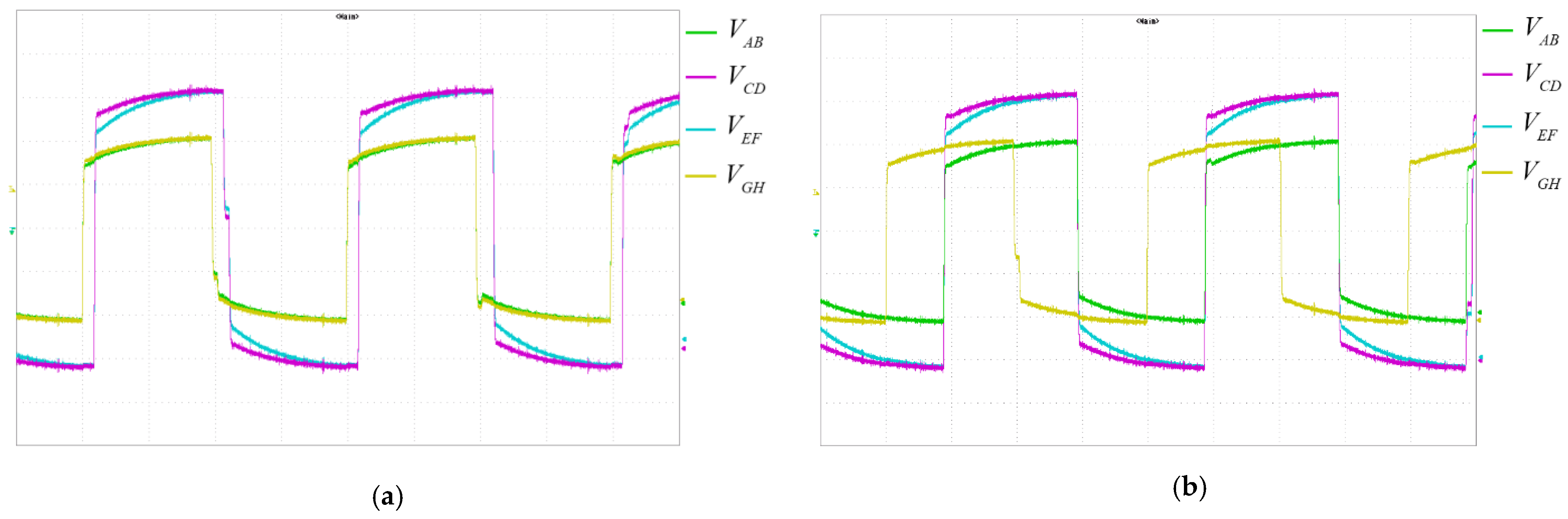
Figure 14 shows the voltage waveforms across the windings of the HFT when the voltages
V1 =
V4 = 400 V and
V2 =
V3 = 600 V and the switching frequency
fsw = 50 kHz. The power in each port provided by the photovoltaic and the energy storage systems is 50 kW each and two EVs absorb 50 kW each. In
Figure 14a, the EVs are fed by the photovoltaic and the energy storage systems; thus, the phase shift between the FBs of the port 1 and port 4 is close to zero (
ϑ14 = 0), while the phase shifts
ϑ12 and
ϑ13 are close to 1.5 μs.
Figure 14b shows the voltage waveforms when the photovoltaic system provides 100 kW and the other loads absorb 33.3 kW. In this condition, the phase shifts
ϑ12,
ϑ13, and
ϑ14 are close to 4.7 μs.
Figure 15 shows the voltage and current waveforms in the case of P
1 = P
2 = P
3 = P
4 = 50 kW and in the case of P
2 = P
3 = 33.3 kW and P
4 = 100 kW. Note that the experimental results, like the simulation results, confirm the proposed analytical analysis.
5. UNIFLEX Three-Port Converter
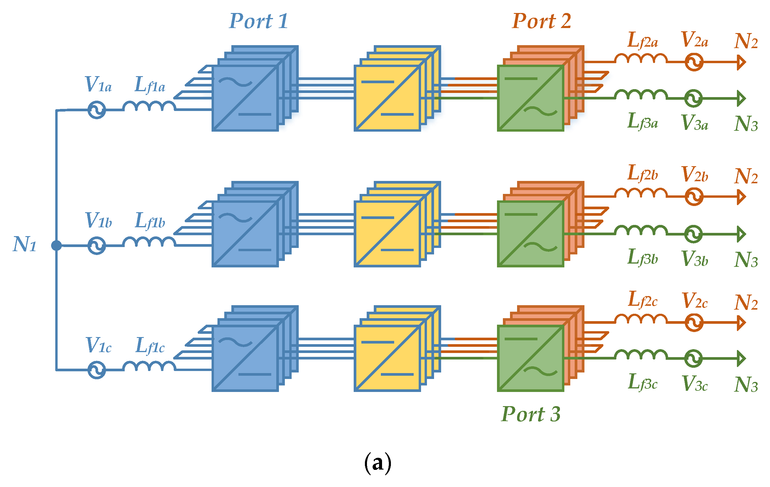
The UNIFLEX-PM three-port converter is able to interface different loads and/or sources, including renewable energy sources or energy storage systems, while interconnecting multiple utilities in AC. The UNIFLEX-PM three-port concept is illustrated in
Figure 16a, where one possible configuration is illustrated: Port 1 and Port 2 are interfaced to MV lines, while Port 3 is devoted for a LV line. The converter is based on a per-phase modular cascaded architecture, using four identical modules per phase. The single module, whose conceptual schematic is shown in
Figure 16b, is composed of an isolated bidirectional AC/DC/AC multi-stage converter.
A nine-level Cascaded H-Bridge converter has been used to interface the MV line on Port 1, while a DAB structure, including a medium frequency transformer, is used as isolation barrier; the Port 2 interface to the other MV grid is built with a seven-level Cascaded H-Bridge converter, while a single H-bridge is used for LV connection of port 3. On the DC side, each H-Bridge on Port 1 is connected, via an isolated DAB converter and parallel capacitor C, to another H-Bridge on Port 2 or Port 3. A series input filter LfPx, with its inherent parasitic resistance rLf, is applied to each phase x = a, b, c belonging to Port P = 1, 2, 3 and it is included to separate the voltage vCPx produced by the converter from grid voltages vPx and provides an attenuation of current harmonics. Due to the modularity of the converter, the voltage and current ratings can be easily adjusted by an appropriate trade-off between the number of modules and power semiconductors selection.
5.1. UNIFLEX-PM Three-Port Control
A per-phase predictive Dead-Beat (DB) current control has been implemented for the UNIFLEX-PM three-port configuration. This choice is motivated by the effectiveness of the current tracking of DB controllers, able to obtain an ideally zero error in the next one, two, or more sampling periods, depending on the selected prediction horizon [
75]. The DB control output is the AC voltage reference of the converter at the current sampling time, which is chosen by imposing the predicted current value at the next sampling period equal to the desired reference. The desired output voltage is then applied by PWM modulator. Considering the generic phase
x of the converter Port
P, the control law can be derived starting from the AC model shown in Equation (8):
where
rLf is the parasitic resistance of the inductance
Lf. In order to allow the implementation on a digital controller, a discrete time model is required. Considering a sampling period
Ts and one period for the prediction horizon, the discrete equation, calculated at the sampling instant
tk + Ts to compensate the delay introduced by the digital controller, is obtained as follows:
Imposing the current
iPa at the next sampling interval equal to the current reference
iPa∗, the reference voltage
vCPa∗ to be produced by the converter at Port
P is obtained as follows:
Current references
iPx∗ are calculated based on the desired amount of active and reactive power on each Port:
where
, with
as the reference value for active power,
the reference value for active power, and
the desired power factor.
The UNIFLEX-PM converter is expected to control the power flow between the three ports at any power factor. However, in [
76], a detailed analysis has pointed out some constrains on the power flow capability. As can be seen in
Figure 17, the operating areas are divided into four zones according to the active power on Port 2 and 3. The red and green lines represent the active power limits on Port 2 and on Port 3, beyond which a unity power factor operation cannot be reached. In the operating areas A and D, no reactive power on Port 1 is required, while in areas B and C, a certain amount of reactive power is needed to assure the power balance.
The equations that link P2 and P3, identifying the operative areas, can be expressed as:
Bound C–D:
where
VMAX identifies the maximum output voltage of each H-Bridge and
vd is the real part of the grid phasor on Port 1. The active power flow control on Port 1 is not subject to constraints, while the reactive power
Q1 on Port 1 has to be imposed to furnish enough circulating current to transport the power between the converter ports, depending on the operative point.
Q1 boosts the current amplitude so that the control is able to deliver the power demanded by Port 2 and Port 3. In the literature, several methods have been proposed to share the reactive power [
77], mainly based on the following methods: (1) active and apparent power proportional share; (2) active and apparent power fixed share; (3) fuzzy logic approach. The latter is used to provide the set points of active and reactive power flow.
5.2. UNIFLEX-PM Three-Port Simulation Results
Simulations of the full system have been carried out considering the parameters of
Table 3.
Figure 18 shows the obtained results in several operating points.
Figure 18a shows the operating points under consideration and the active power trajectory on Port 2 and 3. The active power is well tracked through all the operating areas under the constraint of demanding reactive power on Port 1 when operating in area B and C.
Figure 18b,c show, in detail, the active and reactive power tracking waveforms on the three ports. In the considered operating condition, the reactive power is kept to zero on Port 2 and 3, while it is required on Port 1 so as to permit current circulation in operating zones B and C.
Both active and reactive power are well tracked with fully acceptable ripple.
Figure 19a–d illustrate significant waveforms for the UNIFLEX-PM converter when operating in area C. In
Figure 19, the currents are affected by a limited harmonic distortion (THD% ≈ 4.5% for phase currents in Port1), while the converter voltages have a symmetrical pattern. On the other hand, the DC-Link voltages on each phase are balanced in terms of mean value, while presenting a ripple lower than 5%. The ripple originates from the DC-link active balancing algorithm implemented in the modulator [
78] and to the different power flow demands for the DC-Link between Port 1 and 2 and between Port 1 and 3.
6. Conclusions
Considering the new relevant role of Power Electronics Converters in the implementation of flexible distribution grids that enable the concept of Internet of Energy (IoE), this paper reviewed different topologies of multi-port power electronics converters to be used as an energy router solid-state transformer (SST) in AC, DC, and hybrid distribution grids. Multi-port SSTs have been discussed in detail and classified depending on their design characteristics, such as isolation capabilities, number of stages and ports, and input/output connections. Their advantages and limits have been identified in order to highlight the potential benefits of SSTs in distribution applications, especially in terms of integration of renewable energies sources and network active nodes usage among the others. A comparison of the most relevant features and design specifications between popular topologies has been provided through a comprehensive and effective table.
An excursion of the European energy policy framework, with specific reference to the Italian case, has been presented to understand if the flexibility, modularity, and efficiency of multi-port SSTs can already be included in the framework of the electricity grid management. Thus, it was pointed out that multi-port SSTs have all the technical requirements to reach this aim according to European standards if they are economically feasible with reference to each specific implementation project.
Finally, two case studies of multi-port topologies were addressed: an isolated multi-port bidirectional dual active bridge DC-DC Converter useful for fast-charging stations and a three-port multi-level AC-AC power converter in H-Bridge configuration, denoted as UNIFLEX-PM, able to replicate a network active node. The former is composed of four different FB sections able to manage, for example, but not limited to, a photovoltaic source, a stationary storage system that can operate as either a source or a load, and up to two vehicle battery units. All ports are connected through a high-frequency multi-winding transformer, which allows creating a magnetic node and guarantees galvanic isolation among the aforementioned ports. Simulation and experimental results were shown in order to validate both the proposed analytical analysis and the power flow control efficiency. The latter configuration, whose topology and control strategy were presented, demonstrated to be able to efficiently route and control energy under different operating conditions within a distribution grid, by replicating a network active node and by limiting grid harmonics distortions.


 ,
, 


