Review

Research on Oil Mist Leakage of Bearing in Hydropower Station: A Review

1
College of Water Conservancy and Hydropower Engineering, Hohai University, Nanjing 210098, China
2
College of Energy and Electrical Engineering, Hohai University, Nanjing 210098, China
3
Luoyun Water Conservancy Project Management Office of Jiangsu Province, Suqian 223800, China
4
Technological Institute of Merida, Technological Avenue, Merida 97118, Mexico
*
Author to whom correspondence should be addressed.
Energies 2022, 15(7), 2632; https://doi.org/10.3390/en15072632
Submission received: 27 February 2022 / Revised: 22 March 2022 / Accepted: 28 March 2022 / Published: 4 April 2022
(This article belongs to the Collection Electric and Hybrid Vehicles Collection)

Abstract

:
Hydropower is a clean and renewable energy, fundamental to the attainment of a sustainable society. Despite its efficacy and success, there is a need to address the hydroelectric stations’ oil throwing and mist leakage, resulting in the deterioration of the generating units, water, and biodiversity. The conventional engineering measures to deal with oil mist leakage include: the reduction in the operating pad and oil temperature, optimization of the oil circulation loop in the oil tank, improvement of the sealing performance, and design of the oil mist emission device. However, the problem of oil mist leakage of bearings is complex, intractable, and cannot be solved by only one method. Numerical simulation can help to solve the oil mist problem and make up for the shortage of engineering measures. Yet, the mass transfer, involving multi-component and multi-phase flow, becomes a limitation for many numerical studies. As a result, this paper seeks to integrate the solutions by reviewing two influences: the global measures of oil mist leakage proof in the oil tank of bearings in the past 40 years, and the views and experiences of engineering practices. These findings offer some relevant insights into the effectiveness of the applied methods and solving of the oil mist leakage problem.

1. Introduction

Energy is the driving force for a country’s sustained economic growth [1]. Hydropower, an emission-free energy resource, is credited for 71% of the global renewable electricity production [2]. Its large acceptance includes cost-effectiveness and significance in confronting global warming and the intermittency of other renewable resources. In the last fifty years, as a result of academic and industrial advances, the installed capacity of power stations has increased significantly, requiring the development of larger hydraulic turbines and generators [3] (shown in Figure 1). Furthermore, given the trends to inevitably lead to a higher load demand of the bearings, they are required to support increasingly axial thrust of hydro-generator sets, generating many questions in need of further investigation.
Despite various available options, the vast majority of the bearings in the world still correspond to the 19th-century-invented dynamic pressure bearings. Research into their commercialization has a long history. Initially, Tower and Reynolds proved the existence and possibility of applying dynamic oil film in 1880 and 1886 [4]. In 1912, Albert invented and installed the world’s first dynamic pressure bearing on a 12 MW hydraulic generator unit in Holtwood [5]. After continuous research and industry success, bearings based on oil lubrication were widely applied and promoted, increasing the oil tank’s load design capacity and volume. At present, the largest capacity of the bearings was nearly 6000 tons [3], and that of the oil tank was 32,000 L [6].
Along with this bearing load capacity growth, however, there is increasing concern over the inevitable oil throwing from the tank in the form of oil droplets and oil mist leakage due to the centrifugal force and high temperature [7]. This rise in temperature is due to viscous shear stress due to the enormous pressure applied in the oil film [8]. Heat buildup may cause bushing bearing failure. Two well-known solutions are the following: the deliberate shutdown of the power stations [9,10,11] to avoid safety risks, complicating the power grid management; and the use of high-temperature bearing designs, as found in the minority of power plants, such as Bratsk Hydropower Station [12], ROSEIRS Hydropower Station [13], Karot Hydropower Station [14], and Orujie Hydropower Station [15]. Some common events of oil mist leakage by bearings in power stations are shown in Table 1.
Although oil mist leakage causes insignificant immediate damage to the unit, the safety and water problems brought about by the oil droplets and oil mist diffusion remain a growing concern among experts [28,29,30]. Some effective methods for bearing oil mist leakage proof have been explored in engineering practice for nearly a century. The advances in numerical simulation technology in the past three decades have been crucial in studying the effects and mechanism of this phenomenon [31,32], resulting in bearing designs of excellent performance [33,34,35]. To back up their claims, some scholars have combined numerical methods with experiments [36,37], but the drawbacks include the high cost of the equipment and labor-intensive analysis. To date, there is no complete and systematic numerical simulation method for the oil mist leakage problem in the bearing oil tank of the hydraulic turbine.
In order to establish the best strategies for the management of oil losses, this paper reviews the events of bearing oil leakage in the past 40 years around the world, the treatment methods, the mechanism of oil mist generation, and the engineering experience. Based on the numerical simulation results of lubricating oil movement, the general thinking and some critical issues in the bearing oil mist simulation are summarized and discussed. Essential insights are given for reducing its impact on performance and the environment.

2. The Generation, Classification, and Damage of Oil Mist Leakage

2.1. The Generation Mechanism of Oil Mist Leakage

As a highly processed petroleum product, lubricating oil contains various chemical components and has different volatilities. Under a normal unit operation, the atomization of lubricating oil becomes inevitable as long as the mixture of oil and gas exists at a specific temperature [38]. As Jung K. et al. [39] argue, the critical reason for bearing oil throwing is the centrifugal force during operation.
The process of oil throwing and mist leakage can be described in four steps: (1) the rotating parts (such as shaft collar and oil slinger) will spin the oil, with frictional heat building up, increasing the oil temperature and fluidity [40]; (2) as the oil splashes under the action of the centrifugal force, the contact area between lubricating oil and air increases, intensifying the lubricating oil atomization [41]; (3) the rotating oils’ surface profile becomes parabolic and forms foam due to impingement on the inner parts of the tank; (4) the pressure difference between the inside and outside the oil tank increases with mist oil accumulation, eventually leading to mist leakage [42]. Other contributing factors include the oil quality decline, negative pressure zones, sealing performance deterioration, manufacturing and installation inaccuracies, oil tank structure design being unreasonable, and insufficient condensation space of the tank [38,43,44]. For hydraulic turbine units, the oil mist leakage usually occurs at the thrust, lower guide, and water guide bearings. Figure 2 shows the layout of the bearing positions of a hydraulic unit.

2.2. Classification of Bearing oil Throwing Problem

The bearing oil throwing can be divided based on position into internal and external. These are discussed in detail in Section 2.2.1 and Section 2.2.2, respectively. At present, the external type accounts for most of the oil leakage problems.

2.2.1. Internal Oil Throwing

As shown in Figure 3a, the thrown oil follows a path. The key causes can be listed as follows:
  • The gap between the thrust oil-retaining tube and the shaft is excessive [43];
  • The distance between the top of the oil-retaining tube and the oil surface leads to pumping effectively, and the oil surface fluctuates greatly [46,47];
  • There is no oil-receiving box between the oil-retaining tube and the shaft, thereby forming an oil mist leakage channel [48];
  • The Reynolds number in the oil-retaining tube area is larger, meaning the turbulence is intense during operation, resulting in oil flow fluctuations [43,49];
  • Operation of the air cooler to minimize the temperature effects of a high-speed generator. This is because the continuous blow and change of flow velocity will produce low pressure in the upper and lower regions of the central body of the generator rotor. The low-pressure zone will increase the oil level height, inducing oil droplets and mist leakage [50]. The path of the blast is shown in Figure 4.
  • An eccentricity between the thrust head and the oil-retaining tube or the inner wall of the tank is produced during the installation. The effect of the uneven oil ring and pump are similar, resulting in oil pumping and internal throwing [51].

2.2.2. External Oil Throwing

External throwing refers to oil (mainly oil mist) being thrown from the gap between the rotating parts and the cover plate to the outside of the cover plate [43]. The oil throwing path is shown in Figure 3b. The main causes are increased pressure inside the oil tank and the lax seal. The specific reasons are as follows:
  • Considerable space limitation of the volume of the tank, and thus of the oil mist condensation [48];
  • The sealing structure of the oil tank seal cover is unreasonable, forming the main channel of the oil leakage [48];
  • The viscous shear action of the oil during high-speed operation, thereby converting substantial mechanical into heat energy [52]. As the lubricating oil expands, the internal pressure becomes greater than the external’s, developing the leakage of the oil mist. This leakage can be worsened if the low-pressure zone is close to the sealing cover plate [6,48].
  • Oil leakage exists on the bearing assembly surface and pipeline, worsening the problem [48];
  • The generator structure manufacturing is unconventional, or the installation and debugging are inaccurate. For example, the offset distance between the rotating part and the geometric center of the oil tank can be excessive, resulting in violent oil fluctuations and collisions [53];
  • Augmentation of the clearance between the bearing seal cover shaft results in oil mist leakage [54]. This clearance can easily misalign due to the large vibration of the high-head suspension unit.
Figure 4. The blast path and low-pressure zone [55].
Energies 15 02632 g004

2.3. Damage Caused by Oil Mist Leakage

2.3.1. Pollution to the Power Plant and Its Watershed Environment

The oil droplets and mist expelled may reach the leakage collection well and pollute the power plant’s water source [56]. In addition, some of the oil mist and droplets will inevitably fall on the top cover and be discharged downstream together with water leakage, polluting the water quality and affecting the ecological environment of the downstream rivers [43,57,58]. For instance, the leakage event of lubricating oil VG 46 from Balimela Hydropower Station seriously polluted the reservoir, affecting plankton and fish production. It is shown in Figure 5a [25].

2.3.2. Damage to the Insulating Performance of Electrical Equipment

Oil mist, following overflow, will adhere to the stator and rotor wire bar, magnetic pole, magnetic yoke, and other generator components. Oil mist is highly corrosive, reducing the performance of the insulation and unit service life [59]. Furthermore, oil mist may overflow into the slip ring chamber, causing the slip ring’s and the carbon brush’s contact to spark, affecting the life of the slip ring [38]. Statistically, bearing oil mist leakage is one of the crucial reasons for the mechanical failure of the equipment [60].

2.3.3. Disruption of the Safe and Stable UNIT Operation

Oil loss in the tank due to leakage causes bush-burning accidents [50]. The mixture of oil mist with dust tends to gather in the ventilation groove of the rotor’s stator core and magnetic pole, affecting the generator’s ventilation and heat dissipation; the efficiency and safety of the unit are also compromised. Moreover, if the oil mist condenses on the air and mechanical brake ring, oil fumes [38] will arise due to the high temperatures in the braking zone.

2.3.4. Intensification of the Costs and Workload of Unit Maintenance

Personnel are required to constantly check and replenish the oil [54] in the case of dropping oil levels in the tank, reducing the cost-effectiveness of the power station. The oil droplets and mist will disperse into various zones: the cover of the generator oil tank, the central body of the frame, the vent of the generator air cooler, the lower frame, the floor of the plant workshop, and other parts. Figure 5b,c shows the oil mist attached to the lower guide maintenance platform and lower frame of a power station in Jiangxi, China. Figure 5d,e shows the oil mist and droplets accumulated on the top cover and a power station’s turbine guide bearing cover during annual maintenance. The inspection, cleaning, and removal of the oil [45] are labor-intensive and significantly costly.

2.3.5. Negative Effects on the Health of Operations Personnel

Oil mist circulating along the wind path will gather significantly in the wind tunnel [61]. Inhalation of oil mist during touring inspection can affect the lung health of operators. In addition, the ground can be slippery due to temperature drops from the oil mist condensation, causing potential safety risks [59].

3. Examples of Engineering Research and Some Common Solutions

Since the 20th century, research has focused on optimizing the bearing and seal structure, that is, to limit the oil mist in the oil tank by ‘blocking’ [7]. Only after the 1980s, an alternative methodology was proposed, the “evacuating”, through the first oil mist discharge device. Today’s generally accepted methods include the combination of the two methods.
From a project perspective, engineers usually emphasize the leakage attenuation through four measures: (1) reduction in the tile and oil temperature during operation; (2) optimization of the oil circulation loop; (3) improvement of the sealing performance; (4) effective evacuation of the generated oil mist. Section 3.1, Section 3.2, Section 3.3, Section 3.4 discuss these steps in detail.

3.1. Reduction in the Operating Pad and Oil Temperature

Reducing the oil and tile temperature can help reduce the formation of oil mist. Two accepted methods include:

3.1.1. Optimization of the Structure of the Pad

In the Hongping Power Station, the highest pad temperature dropped from 85 °C to 70 °C [62] by replacing the metal spring cluster support, increasing the outer diameter, and optimizing the oil inlet edge of the thrust pad. The spring-supported thrust bearings containing support blocks were replaced in the Cataract Power Station, and the pad temperature was reduced from 83 °C to 50 °C [17]. Singh A.P. et al. [63] optimized the thickness and inclination of the oil film to minimize the bearing capacity of the oil film during operation, thereby reducing the temperature of the bearing pad. In an analogous manner, the Itaipu Binacional Power Station modified the thrust bearing and optimized the oil film by reducing the thickness in order to augment the bearing capacity. As a result, a reduction ensued from converting the oil’s mechanical into heat energy [64].

3.1.2. Improvement on the Cooling Cycle Efficiency of the Lubricating Oil

Various plants have invested in newer, higher-capacity, and more efficient cooling systems, effectively reducing the oil losses. In Shuibuya Power Plant, the external circulation cooling was changed from runner-pump to forced. The temperature of the pad reduced on average from 69 °C to 62 °C and, in terms of maximums, from 74.5 °C to 70 °C [61]. With increasing cooling system power during renovations, the pad temperature dropped from 68 °C to 63 °C [65] in the Yeywa unit, and the temperature of the pad to oil from 40 °C to 28 to 29 °C in the Dongfeng Hydropower Station [66].
Likewise, the lubrication from the oil can be replaced by adding anti-wear agents to pure water. The high-pressure water-lubricated bearings can reduce wear by 50% [67] compared to the oil method, effectively solving pad temperature rise and oil mist leakage [68,69,70,71]. Despite being functional, it is not yet cost-justified in the industrial sector.

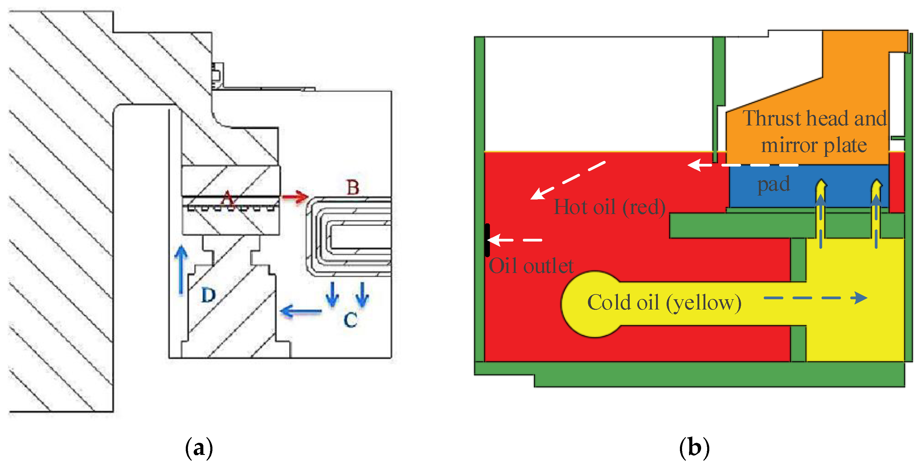
3.2. Optimization of the Oil Circulation Loop in the Oil Tank

A well-designed oil-saving circuit system can minimize oil mist generation, achieving good results [19,72]. The cooling method of lubricating oil is mainly divided into internal and external circulation cooling. The oil flow paths are mainly related to the oil circulation cooling mode. The choice of an internal or external circulating oil circuit is related to the structure of the generator bearings (the oil tank has enough space to accommodate the cooler), unit capacity and speed, bearing, thrust bearing load and size, and economic investment. The principle aims of redesigning flow paths should be: (a) improve heat dissipation efficiency; (b) reduce stirring loss of components; (c) prevent oil mist leakage. The existing measures to improve the flow paths are based on these three design principles, such as oil stabilizing plate, pressure balance holes, oil-retaining ring, oil slinger, oil-pressing cascade, or improving the structure of the oil tank cover. These measures aim to maximize the heat exchange between hot oil and cold oil, reduce the collision of oil and components, and restrain the generated oil vapor in the tank.
One anti-oil throwing measure is shown in Figure 6, where the lubricating oil’s fluctuation and loss are reduced by adopting an oil stabilizing plate (as shown in Figure 6), pressure balance hole, oil-retaining ring, and oil slinger [23,73,74,75,76,77].
There is a considerable volume of published studies in power stations, emphasizing the use of anti-throwing structures in the tank. For example, in the Xixiayuan Power Station, an oil baffle plate and ring were installed to promote oil temperature difference convection [78]. Ertan Power Station optimized the oil circulation loop through the oil-pressing cascade and oil slinger [79]. In Kamenogorsk Hydropower Station, deflection rings were installed above the oil surface to prevent oil mist diffusion and leakage [80]. As mentioned, in order to help stabilize the oil level and to reduce the energy and velocity gradient obtained by the oil during the operation [51], two actions may be taken: (1) increase the distance between the shaft and oil-retaining tube [81]; (2) install two to three layers of reinforcing rings on the oil-retaining pipe wall.
Other authors have noted the importance of re-designing the cover plate structure. For example, Deng Y., et al. [82] modified the cover plate of the generator thrust tank and reduced the leakage rate of oil mist from 4.9 m3/h to 0.36 m3/h. Some plants also install fans on the inner wall of the thrust head to perform two actions: (1) to prevent oil from channeling [51] using the pressure-generated wind; (2) to condense the oil mist on the board through the use the staggered baffle in the respirator [83].
As seen in the literature review, improving the oil circulation system can only minimize but not eliminate the production of oil mist [56]. Therefore, a proper sealing design is critical, as shown in Section 3.3.

3.3. Improvement of the Sealing Performance

Improving or replacing the sealing structure is the most effective and convenient method to deal with the problem of oil mist [6], as substantiated by the actions of power plants [84,85,86]. For example, Ertan Power Plant replaced the original oil tank cover plate with a contact oil baffle. The effect was highly positive [53,87] during the two years of operation. Whereas, in Shuibuya Power Plant, negative pressure was formed to prevent oil mist leakage [61] through two actions: (1) replacing the contact seal cover; (2) installing the exhaust fan in the upper chamber of the seal. The Chongqing Jiangkou Hydropower Station used the contact oil baffle [49] to compensate for the gap between the original labyrinth seal tooth and the shaft. Sanbanxi Power Plant upgraded the follow-up sealing material [88] to increase the performance of the plate-sealing tooth of the original oil cover. In Shawan Hydropower Station, the three-comb labyrinth rings were removed during renovation, and the CX-FS sealing device was used instead to ensure no gap between the cover plate and shaft collar during operation [54]. Wanjiazhai Hydropower Station replaced the seal from the pneumatic-type labyrinth to a contact-type seal with self-compensation. In support of the design practice, the combination of the gas sealing cavity with two sealing teeth has induced a perfect sealing effect [89].
Thus far, engineering practices have shown some interesting findings. First, the seal body of the labyrinth seal is prone to break and wear, and the seal tooth is difficult to compensate with the shaft. Second, after a long-term operation, the contact sealing strip is susceptible to oil and dust accumulation. Third, even if the felt gland seal’s performance exceeds the labyrinth’s, oil mist leakage can be present due to a pressure drop [84]. Summarizing the various factors associated with oil losses, an ideal seal must contain the following properties: resistance to high temperature, corrosion aging resistance and wear, good sealing tooth follow-up, and good scalability of the sealing strip. With the continuous advancement of science and technology, the contact-type has mostly replaced the non-contact seal, although the design of the zero leakage seal is gaining relevance in the field [90].

3.4. Design of Oil Mist Emission Device

A major problem of the significant oil mist accumulation in the tank is the inevitable leakage caused by the pressure difference. The oil waste consequences are recognized as a serious environmental concern, and these may be alleviated by installing oil mist emission devices in combination with the hydropower station’s anti-pollution strategies [59]. As a case in point, during the transformation of the Longtan Hydropower Station, several oil mist absorption ports were uniformly arranged between the contact seal and the oil barrier of the lower guide bearing [42]. Whereas, in the Ertan Power Station, the escaping oil mist was directed and collected into an oil mist separator, installed in the outer tank, for posterior centralized treatment [78].
Because many power stations manually control the oil mist emissions, the reliability is still poor. Automatic emissions technology, based on neural network algorithms, could become more common in the future for the governance of oil mist overflows [91,92,93].
Unfortunately, unless power plants adopt several oil-saving methods, the positive environmental effects are minimal; thus, continued efforts are being made to establish the most appropriate direction. The main actions are the following: developing the bearing pad with better performance, improving the cooler’s efficiency, designing a reasonable oil circulation path, maturing the contact seal and zero leakage seal, and advancing the oil mist automated emission technology. The measures taken by some hydropower stations are highlighted in Table 2.
It is worth saying that it is crucial to collect the statistical characteristics of oil mist leakages of bearing in hydropower stations to research the problem of oil mist leakage further, such as in the work of Burgan, H.I. et al. [94] on gauged rivers, which will be helpful for the long-term management and detection of oil mist problems in power plants in the future.
Table 2. Comprehensive measures for oil mist leakage problem.
Hydropower StationMeasuresCountry
Ertan [95,96]Raise the oil retaining ring, replace the contact seal, and install the oil slinger and mist respiratorChina
Dalanshan [55]Replace the oil mist absorption device, the oil tank cover, and sealChina
Longtan [87,97]Increase the power of the oil mist absorption device. Add oil breathing device; an oil mist suction pipe is arranged in the sealing tooth cavity China
Xiluodu [98,99]Renovate the sealing cover structure, increase the oil slinger, and replace the oil tank sealChina
Shilong [100]Add comb labyrinth oil-retaining tube, connecting pipes, and oil-return holes in upper and lower oil tanks. Install oil baffle plateChina
Shuibuya [101]Increase the height of the oil-retaining tube and the number of oil respirators. Install the oil-pressing vane on the inner wall of the thrust head and adopt the contact seal China
Xiaolangdi [24,102,103]Increase the height of the oil-retaining tube, lower the oil level of the oil tank, and increase the number and diameter of oil-return holesChina

4. General Thinking and Some Critical Issues of Numerical Simulation

Although engineering approaches exist in the literature regarding the oil waste problem, drawing an overall conclusion is extremely problematic since power stations’ designs and, thus, solutions, are unique. Consequently, more recent attention has focused on providing the actual oil flow field in detail to formulate an appropriate and reasonable renovation plan.
A large and growing body of literature has investigated the oil tank flow field from a numerical simulating perspective. Compared with experimental solutions, the numerical method often uses less workforce, time, and material resources. It can assess the mechanisms and impact of oil mist production and its influence on the components and the environment. Nevertheless, as Novotný P., et al. [104] point out, the attainment of the general analytical solution of the thrust bearings oil tank is still challenging. In the literature, the reliable numerical solutions are based on different methods: numerical finite difference (FDM), finite element (FEM), and finite volume (FVM). Authors such as Pajączkowski P., et al. have optimized and modified the bearing based on numerical simulation to improve the performance [105,106,107].
At present, many simulations rely on commercial software [104], such as Fluent, CFX [108]. It has been used to effectively model a single physical problem, such as bearing thermal effect [109], flow cavitation [104,110], multi-phase flow [111], and turbulence. The results are validated by worldwide industries and academics.
In the paper, the numerical performance of the oil mist problem has been associated with several issues. These include modeling simplification, handling of bearing dynamic and static clearance, selection of calculation models, and setting boundary conditions for different types of bearings.

4.1. Research on Simplification of Modeling

Historically, some scholars have simplified three-dimensional into two-dimensional modeling problems through symmetry properties, significantly reducing the number of grids and computing time [82,112]. However, these results may underestimate the role of the whole structure interactions and, hence, deviate from real calculations. By virtue of this, support and information on the three-dimensional model, including techniques and reliability, has increased over the last few years. The three-dimensional model structure of typical thrust bearings and combined bearings is shown in Figure 7a,b [13,113].
Because the three-dimensional model structure is often too complex, it is necessary to simplify the model by ignoring some unimportant parts. For example, some scholars apply a 1/12 symmetry condition between the bearing oil tank and pad, as shown in Figure 8a [114], or a 1/6 symmetry condition of the thrust bearing pad, as shown in Figure 8b [115]. The whole part can be considered in simple and small cases, as shown in Figure 8c [116].
A severe weakness with this argument, however, is the low meshing of the model, inevitably leading to an unclear gas-liquid interface (Figure 9a), compared with a 1/12 model (Figure 9b). Therefore, in the case of limited computational resources, considering that most oil tank models have symmetrical structures, periodic boundaries for symmetry models can be used to describe the oil movement better.

4.2. The Tackling Method of Bearing Dynamic and Static Clearance

The issue of dynamic and static clearance arises in the model simplification. The clearance is generally divided into three categories: (1) between the mirror plate and thrust pad containing pressure oil film (the clearance between the shaft collar and bearing pad); (2) between the shaft and sealing cover; (3) between the oil-retaining tube and the shaft. The tackling of these three clearances is discussed in Section 4.2.1, Section 4.2.2, and Section 4.2.3, respectively.

4.2.1. Dynamic and Static Clearance with the Pressure Oil Film

Oil film plays a vital role in the operation of the whole bearing, affecting the pad temperature, load capacity, mechanical efficiency, and service life [114,117]. Nevertheless, the oil film thickness is often minimal at the micron level [41], and the critical Reynolds number of the oil film flow is about 1500 [118]. In regular operation, the oil film flow is laminar, while the rest of the lubricating oil in the tank is turbulent, leading to different lubricating oil flow conditions in the entire tank.
Dadouche A., et al. [119,120,121] believed the pressure oil film had a crucial role in the thermal effect of the thrust bearing. Zhang et al. [41] assessed the significance of the clearance by ignoring the pressure oil film but not its influence, and the pad temperature and oil temperature measured during actual operation are taken as boundary conditions of numerical calculation.
Some scholars use grid block technology to separate the mesh in the oil film region to mostly study the parameters and bearing capacity of the pressure oil film. For example, Lu Deping, et al. [114] adopted the mesh lap method to deal with the oil film clearance. Wasilczuk M. also constructed an oil film clearance grid [122] to solve the oil film flow question. Pang Jiayang, et al. divided the oil film mesh and used an interface to connect the dynamic and static regions [116], as shown in Figure 10a. According to Qu Bo et al. [123], the oil film must be divided into at least five to seven layers to complete the grid independence verification. An oil film’s grid is usually between 0.6 and 1.1 million [124,125]. In order to calculate the flow of the oil film, Novotný P., et al. applied a 1/6 symmetry on the bearing pad but obtained 5 million grids, a large demanding resource, as shown in Figure 10b [104].
For the bearing oil mist problem, the focus is not the oil film but the oil flow field in the tank. If the model structure is relatively complex and the structure size is relatively large, building a fine oil film gap grid will only further increase the calculation consumption. In this situation, it is more appropriate to ignore the oil film.

4.2.2. Clearance between the Shaft and Seal Cover

The seal leakage issue has been studied well in unidirectional flow through numerical methods, such as BFM [126], steady-state simulation solution [127,128], and unsteady simulation solution [129,130]. However, the given methods suffer from predicting multi-phase flow environments, such as oil, liquid, and gas [131], due to the uncertainty of the drag coefficient of the tank seal of the fluid and small clearance; particularly, the small gap for the contact seals restricts the precision of the simulations. Furthermore, since the sealing teeth move with the shaft, the clearance tends to disappear.
The oil mist leakage is recognized as inevitable due to the pressure difference working conditions. In its study, scholars often assume the oil tank is a closed environment and judge whether leakage will occur or not by calculating the pressure distribution in the tank [41,82,112,116].

4.2.3. Clearance between the Oil-Retaining Tube and the Shaft

The flow pattern of the lubricating oil plays a crucial role in the clearance. Initially, the oil flow between the oil-retaining tube and the shaft is laminar but then changes (even if stable and at rated speed) to turbulent owing to the rise in the oil temperature and speed. A turbulent lubricant can easily escape from the clearance, resulting in internal oil throwing [41]. Because this clearance interaction is important and generally large, an effective prediction would be advantageous in guiding and detecting the lubricant-related failures.

4.3. Selections of Calculation Models

4.3.1. Rotation Model

The bearing body is often fixed in the models, while the shaft, thrust head, mirror plate, and oil slinger rotate at a certain speed. The rotation can be handled via three methods: single reference frame (SRF), moving walls, and dynamic mesh.
The dynamic mesh can best reflect the actual motion but requires high-quality grids and large computer resources. The dynamic mesh can implement negative volume calculations and is suitable for transient motion with a simple computing domain. Whereas, for a bearing motion, since the oil can be considered steady or in equilibrium [52,114], the SRF or moving wall results are more appropriate. Because the SRF divides the rotation domain and sets the interface, difficulties arise when capturing the minimal gap between the shaft and bearing pad.
A few studies have been conducted on the rotating system. Zhang Chengzhi [41] calculated the oil mist problem of the thrust bearing by setting the mirror plate and the thrust head as the rotating wall and the other wall as stationary. Lu Deping [114] revised this method and set the moving walls to perceive the relative motion effects in a steady-state manner.

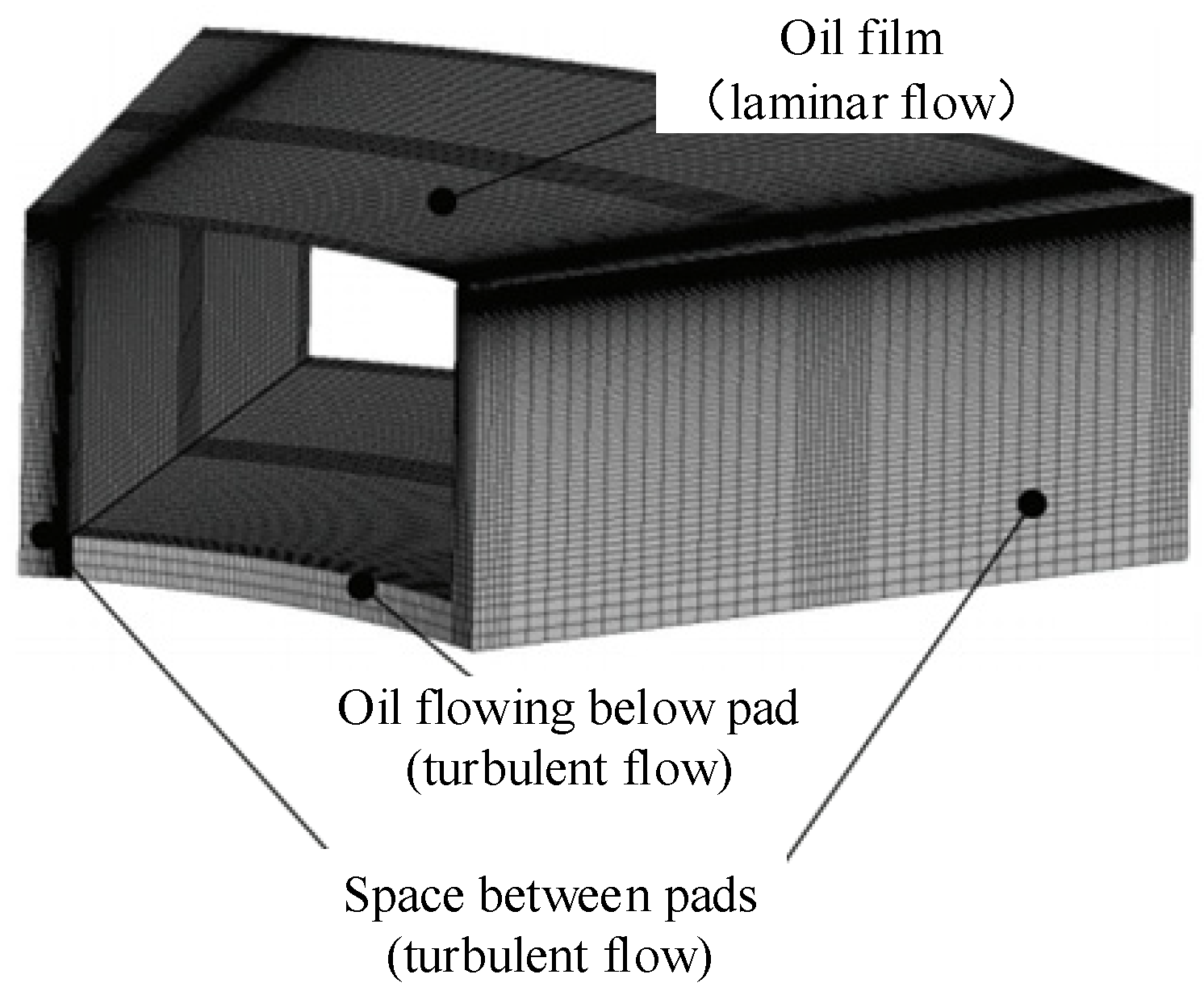
4.3.2. The Turbulence Model

The selection of the turbulence model relies on the best judgment of the researchers. If the focus is on the oil film’s bearing capacity, temperature, and pressure changes, building a micron-scale oil film clearance is necessary. In this case, the SST k ω turbulent model [116,132] is generally used, so the laminar flow is calculated in the oil film zone and turbulent flow is calculated within the bearing pads zone, as shown in Figure 11 [108].
When the oil film is ignored, as the flow pattern in the oil tank is all turbulent, more preference is given to the standard k - ε model [41,82]. However, compared with the standard model, the RNG k - ε model has more advantages in the fluid rotation calculation [133,134]. RNG k - ε model can capture the swirling flow caused by the oil stirring due to shaft rotation and represent the flow well with a large degree of streamline curvature [135]. Therefore, the RNG k - ε model is more suitable for calculating oil mist without considering the oil film.

4.3.3. Multi-Phase Flow Model

Multi-phase flow models, such as the volume of fluid (VOF) model, can be used to study the oil mist, considered as an oil-gas-oil mist three-phase flow. The VOF model has been used to predict several immiscible fluids in the fixed grid, such as water-oil two-phase flow [136,137,138], gas–oil two-phase flow [41,112,114,116], and water-gas two-phase flow [139,140,141]. A set of momentum equations is shared for each phase, with its volume fraction tracked individually in the computational domain. To avoid discrepancies from interface motions, the VOF model converts the interface-related forces, such as surface and adhesion forces, into smoothly changing volume forces so as to determine the motion of each phase and of the interface (indirectly) [137]. Each phase’s fluid fraction function is between 0 and 1. According to the function value, the interface position is constantly reconstructed in the calculation process. As a result, each phase’s volume distribution in the oil mist calculation process may be captured accurately.

4.3.4. Evaporation-Condensation Model

The lubricating oil in the tank is a mixture of highly refined mineral oil and additives, with complex physical properties and different volatilities per component. The lubricating oil vaporizes at 45 °C [43] and changes from liquid to oil mist, which is common in oil-operated equipment [38]. During the operation of the bearing bush, the oil’s operating temperature is 50 to 70 °C, meaning the tank is filled with a mixture of oil, oil mist, and air. In the initial studies of oil throwing in bearings, most scholars only considered the oil-gas two-phase flow and neglected the oil mist. A reasonable approach to tackle this is to utilize the evaporation-condensation model based on the simulation. Oil evaporation techniques mainly include the single component and continuous and discrete multi-component models [142]. The single-component model replaces the actual substance with one component, so the method has high computational efficiency but lacks accuracy [142]. The continuous multi-component model establishes the continuous distribution function with the density or molar mass as the independent variable based on continuous thermodynamics. The continuous multi-component model is used to describe the distribution of the substance components. However, as a drawback, the evaporation characteristics of each component are limited since coupling with the multi-component chemical reaction mechanism is unfeasible [143]. The discrete multi-component model uses several discrete representative components to replace the actual material. Although the evaporation characteristics of each component can be tracked [144] with good precision, the efficiency is the lowest among the three methods [145].
In analyzing the oil mist problem, it becomes more critical to capture the position and concentration rather than the evaporation effect of the oil mist. The one-component model, where oil mist’s viscosity is considered pure lubricating oil [146], is suitable for computational efficiency. The Lee model [147] derived from the Hertz Knudsen equation [148] is often used in the oil mass transfer process. The Lee model has a simple structure and high reliability, and it is widely used in multi-phase flow and condensation heat transfer problems [147,148]. For this reason, Zhang et al. [41] used the Lee model to calculate the oil vapor distribution in the oil tank.

4.4. Setting of Boundary Conditions for Different Types of Bearings

The setting of the inlet and outlet boundary conditions is usually related to the cooling method of bearing lubricating oil, and the performance of cooling relates to the power generation [149]. The cooling method of lubricating oil is mainly divided into internal and external circulation cooling. The internal circulation cooling cooler is installed in the oil tank. The power equipment lacks oil circulation. The tank can be regarded as a closed body for internal circulation cooling, and oil circulation depends on the pressure difference [150]. Figure 12a,b shows the thrust bearing models with drawer- and vertical-type oil coolers. The oil circulation paths are shown in Figure 13a [114]. The setting of the oil inlet and outlet in the tank under this situation is unnecessary.
For the external circulation cooling method, it is necessary to ensure the low-temperature oil flow into the oil tank, and the full-cycle (hot) oil is discharged to the cooler. Figure 14 shows the thrust bearing model of the external circulation of the external pump. Cold oil flows into the inlet oil pipe through the external pump, while hot oil is discharged from the outlet oil pipe and sent to the cooler. The circulation path is shown in Figure 13b in such a reciprocating cycle. In this regard, it is necessary to consider the problem of the oil inlet and outlet. Generally, the inlet and outlet boundary conditions are often set as follows:
  • Inlet boundary conditions: pressure inlet [151] or mass flow inlet.
  • Outlet boundary condition: outflow [114].

5. Conclusions and Prospects

The need of oil-lubricated bearings of substantial carrying capacity can be attributed to the development of hydroelectric energy. The oil film in the bearing under operation endures tremendous pressure and generates high temperatures due to the viscous shear effect. Under the combined action of high temperature and centrifugal force, the lubricating oil is thrown away from the oil tank in the form of oil droplets and oil mist. These problems pose an unnoticed danger to the environment and safe operation of the units.
In reviewing the literature, the production of oil mist is inevitable, but the leakage can be handled by appropriate methods to reduce the harm. Firstly, the amount of atomized oil can be reduced fundamentally by reducing the pad’s temperature and oil during operation. Secondly, a suitable oil circulation loop can reduce the oil foam generated by splashing and collisions. Thirdly, the excellent sealing structure could avoid oil mist leakage to a great extent. Finally, the oil mist absorption device can evacuate partially accumulated oil mist, causing a significant pressure difference inside and outside the oil tank. In practice, engineers deal with the oil mist leakage problem through the “blocking” and “evacuating” methods.
However, it is often challenging to make targeted plans to deal with the oil mist leakage problem only based on engineering experience since it is time-consuming and laborious. Fast, convenient, and efficient numerical experiment methods can obtain the oil flow field in the oil tank and the cause of oil mist. In modeling, it is critical to simplify the model by using rotating periodic boundaries according to the needs of the research object. The key to improving the calculation accuracy is to select the appropriate turbulence model based on the clearance flow pattern. The VOF and Lee models can be used to calculate multi-phase flow and mass transfer; thus, the location of oil mist can be explored. The selection of boundary conditions according to the bearing type is related to the oil flow circulation path in the whole cooling cycle.
Further research should be taken to investigate the following: bearing pads of higher performance, improvement of the cooler’s efficiency, design of reasonable oil flow path, development of contact and zero leakage seal, promotion of water-lubricated bearings, and oil mist automatic emission technology to solve the problem of oil mist leakage. Improving the computational efficiency of the simulation and the accuracy of the oil-air-oil mist three-phase thermal coupling transition model are also helpful in formulating reasonable schemes and engineering practices. In addition, cloud services, based on the model standardization of cloud services and cloud computing mode, can effectively solve the shortcomings of the isolated and fragmented bearing model and data management, and contribute to better oil leakage management.
In the future, with the development of giant hydraulic turbine units, the size of the thrust-bearing oil groove will become larger and larger. With the rapid development of cloud computing, big data, Internet of Things, and artificial intelligence technologies, the operation and management of hydropower stations will develop in the direction of interconnection, data mining, and intelligent decision-making. Therefore, in addition to the traditional methods mentioned above, future measures to deal with oil mist will be closely combined with the intellectual development of power stations, such as the control and governance of bearing oil mist leakage based on a smart power station (SHS), response and assessment of bearing oil mist leakage through the whole life cycle management and control part, diagnosis and prediction of bearing oil mist leakage built on artificial intelligence (AI), and guidance and solutions of bearing oil mist leakage acquired from cloud services.

Author Contributions

Writing—original draft, J.S.; Writing—review & editing, Y.Z. (Yuquan Zhang) and B.L.; Investigation, X.G.; Supervision, Y.Z. (Yuan Zheng) and E.F.-R. All authors have read and agreed to the published version of the manuscript.

Funding

This work was supported by the National Natural Science Foundation of China (Grant No. 51579080). State Grid Xinyuan Holding Co., Ltd. Technology Project (SGXYKJ-2021-037).

Data Availability Statement

Not applicable.

Acknowledgments

Thanks for the thrust bearing model data provided by the Hongping Pumped-storage Power Station.

Conflicts of Interest

The authors declare no conflict of interest.

References

  1. Jadoon, T.R.; Ali, M.K.; Hussain, S.; Wasim, A.; Jahanzaib, M. Sustaining power production in hydropower stations of developing countries. Sustain. Energy Technol. Assess. 2020, 37, 100637. [Google Scholar] [CrossRef]
  2. Nguyen, T.V.; Elliott, R.J.R.; Strobl, E.A. Hydropower generation, flood control and dam cascades: A national assessment for Vietnam. J. Hydrol. 2018, 560, 109–126. [Google Scholar] [CrossRef] [Green Version]
  3. Liming, Z.; Yongyao, L.; Zhengwei, W.; Xin, L.; Yexiang, X. A review on the large tilting pad thrust bearings in the hydropower units. Renew. Sustain. Energy Rev. 2017, 69, 1182–1198. [Google Scholar] [CrossRef]
  4. De Sousa, F.M.M.M. Study of a Hydrodynamic Thrust Bearing for Hydroelectric Power Stations; Universidade do Porto: Porto, Portugal, 2016. [Google Scholar]
  5. Zabawski, E. Tilting pad bearing history. Tribol. Lubr. Technol. 2020, 76, 8. [Google Scholar]
  6. Wang, W.; Sun, W.; Fan, J.; Lei, X. Analysis and Treatment of Oil Mist Problem for Large-scale Hydro-turbine Generator Units. Hydropower New Energy 2017, 4, 74–77. (In Chinese) [Google Scholar]
  7. Cao, S. Research and Implementation of Oil Mist Emission Control Technology for Hydropower Station Units; Harbin Engineering University: Harbin, China, 2020. (In Chinese) [Google Scholar]
  8. Ashour, N.M. An investigation on large thrust bearings. In Proceedings of the 13th International Conference on Aerospace Sciences & Aviation Technology, Cairo, Egypt, 26–28 May 2009. [Google Scholar]
  9. Nurbanasari, M.; Purwanto, T.S.; Kristyadi, T.; Syamsurizal, D. Failure on Bearing Cooler Coils Connector of Hydroelectric Power Plant. Key Eng. Mater. 2019, 805, 185–190. [Google Scholar] [CrossRef]
  10. Hu, J. Analysis and treatment of bearing oil mist pollution in hydropower station. Mech. Electr. Tech. Hydropower Stn. 1993, 4, 32–37. (In Chinese) [Google Scholar]
  11. Liu, C.; Huang, K.; An, G. Analysis and treatment of oil throwing by water guide for unit of Bulunkou-Gongeer hydropower Station. Mech. Electr. Tech. Hydropower Stn. 2016, 39, 70–71. (In Chinese) [Google Scholar]
  12. Baiborodov, Y.I.; Tereshchenko, A.V.; Aleksandrov, A.E.; Shchetkin, V.S.; Pokrovskii, I.B.; Tukmakov, V.P.; Gurbanov, I.S. Results of full-scale tests of the thrust bearing with elastic metal-plastic segments for the turbine-generator unit at the Bratsk hydroelectric station. Hydrotech. Constr. 1982, 16, 348–353. [Google Scholar] [CrossRef]
  13. Haroun, M.A. Effect of Roseires Dam Heightening on Thrust Bearing of the Power Generation Units; Sudan University of Science and Technology: Khartoum, Sudan, 2017. [Google Scholar]
  14. Tang, X.; Zhang, C.; Sun, L. Analysis on tile burning accident of guide bearing of generator in a hydropower station in Pakistan. Small Hydro Power 2016, 4, 48–50. (In Chinese) [Google Scholar]
  15. Ma, D.; Hu, C.; Rao, J. Analysis and treatment of tile burning reason of water guide bearing in Aolujie hydropower Station. Small Hydro Power 2014, 4, 67–69. (In Chinese) [Google Scholar]
  16. Huang, Q. Analysis and Treatment of Abnormal Internal Oil Spill and High Bushing Temperature of the Lower Guide Bearing in Sanliping Hydropower Station. Hydropower New Energy 2018, 32, 48–50. (In Chinese) [Google Scholar]
  17. Plante, P.; Soule, E.D.; Energy, F.P.L.; Dupuis, M. Thrust Bearing Retrofit: A Case Study of the Cataract Generating Station; Hydro Tech: Quebec City, QC, Canada; pp. 1–9. Available online: https://www.electrisa.com.br/fornecedores/hydrotech/mancais-de-escora-informacoes-tecnicas-ingles.pdf (accessed on 1 February 2022).
  18. Yu, F. Fault analysis of oil-throwing ring of hydraulic guide bearing in Caijiazhou Hydropower Station. Mech. Electr. Inf. 2021, 4, 27–28. (In Chinese) [Google Scholar]
  19. Zhu, Y.; Lin, F. Analysis and treatment of oil throwing defect of hydraulic guide bearing in Unit 2 of Gutianxi Power Plant. Fujian Water Power 2020, 4, 23–25. (In Chinese) [Google Scholar]
  20. Zeng, Z. Analysis and treatment of oil throwing in hydraulic guide rotating oil basin of longmentan Secondary hydropower station. Small Hydro Power 2020, 4, 57–58. (In Chinese) [Google Scholar]
  21. Wu, J. Analysis and treatment of oil dumping by water guide in unit 2 of Zhouning power Station. Fujian Water Power 2017, 4, 13–16. (In Chinese) [Google Scholar]
  22. Lan, R.; Wei, H.; Wu, F. Causes and Control Measures of Dust and Oil Mist from Generators in Yantan Hydropower Station. Hongshui River 2016, 35, 96–97. (In Chinese) [Google Scholar]
  23. Liu, J.; Deng, G. Oil Splashing Treatment for Thrust Bearing of The No. 2 Unit at Dafa Hydropower Station on Tianwanhe River. Sichuan Water Power 2010, 29, 120–122. (In Chinese) [Google Scholar]
  24. Luo, Y. Remedial Treatment of Oil Leakage from Thrust Bearing Oil Retaining Tube in Xiaolangdi Hydroelectric Power Station. Des. Hydroelectr. Power Stn. 2003, 4, 86–89. (In Chinese) [Google Scholar]
  25. Mahesh, A.; Sahoo, S.; Panigrahi, A. Impact of contamination by bamboo decomposition and lubricant oil leak and deterioration of Balimela reservoir water standard at Malkangiri of Odisha. Nat. J. Life Sci. 2014, 11, 1–6. [Google Scholar]
  26. Jin, C.; Bao, Z. Environmental protection transformation of unit of Baoku river hydropower station. Small Hydro Power 2017, 44, 45–65. [Google Scholar]
  27. Peng, S.; Yu, Y. Analysis and treatment of thrust tank oil dumping in Ahai Hydropower Station. Yunnan Water Power 2018, 34, 31–32. [Google Scholar]
  28. Inoue, K.; Deguchi, K.; Okude, K.; Fujimoto, R. Development of the water-lubricated thrust bearing of the hydraulic turbine generator. IOP Conf. Ser. Earth Environ. Sci. 2012, 15, 072022. [Google Scholar] [CrossRef]
  29. Sanz-Bobi, M.A.; Welte, T.M.; Eilertsen, L. Anomaly indicators for Kaplan turbine components based on patterns of normal behavior. In Safety and Reliability–Safe Societies in a Changing World; CRC Press: Boca Raton, FL, USA, 2018; pp. 1003–1010. [Google Scholar]
  30. Olszewski, A.; Litwin, W.; Wodtke, M. Influence of shaft misalignment on water lubricated turbine sliding bearings with various bush modules of elasticity. Key Eng. Mater. 2011, 1390, 128. [Google Scholar]
  31. Ramachandran, D.; Krishnamoorthy, S.; Kannan, R.; Boolingam, S. Oil flow simulations in the lubrication system of a turbocharger. In Proceedings of the Gas Turbine India Conference, Bangalore, India, 7–8 December 2017; American Society of Mechanical Engineers: New York, NY, USA, 2017; Volume 58509, p. V001T04A014. [Google Scholar]
  32. Hashish, E.; Mistry, R.; Kreitzer, S.; Finley, B. Oil leak causes and prevention in large electric motors. In Proceedings of the 2014 Petroleum and Chemical Industry Conference Europe, Amsterdam, The Netherlands, 3–5 June 2014; pp. 1–8. [Google Scholar]
  33. Untaroiu, A.; Fu, G. An optimum design approach for textured thrust bearing with elliptical-shape dimples using computational fluid dynamics and design of experiments including cavitation. J. Eng. Gas Turbines Power 2017, 139, 092502. [Google Scholar]
  34. Jiang, S.; Zhang, S.; Lin, X. Static and dynamic characteristics of high-speed water-lubricated spiral-groove thrust bearing considering cavitating and centrifugal effects. Tribol. Int. 2020, 145, 106159. [Google Scholar]
  35. De Pellegrin, D.V.; Hargreaves, D.J. An isoviscous, isothermal model investigating the influence of hydrostatic recesses on a spring-supported tilting pad thrust bearing. Tribol. Int. 2012, 51, 25–35. [Google Scholar] [CrossRef] [Green Version]
  36. New, N.H. experimental comparison of ooded, directed, and inlet ori ce type of lubrication for a tilting pad thrust bearing. J. Lubr. Technol. 1974, 96, 22–27. [Google Scholar] [CrossRef]
  37. New, N.H. Comparison of flooded and directed lubrication tilting pad thrust bearings. TRIBOLOGY Int. 1979, 12, 251–254. [Google Scholar] [CrossRef]
  38. Yuan, B.; Zhang, L.; Wang, W. Oil Vapor Treatment of Vertical Hydro-generator Bearing. Hydropower Autom. Dam Monit. 2015, 1, 43–48. [Google Scholar]
  39. Jang, G.; Jung, K.; Kim, J. Behavior of fluid lubricant and air–oil interface of operating FDBs due to operating condition and seal design. Microsyst. Technol. 2012, 18, 1373–1381. (In Chinese) [Google Scholar] [CrossRef]
  40. Huo, X.; Wang, S.; Wu, Z.; Fan, S.; Liu, Q. Measures to prevent oil throwing in thrust bearing oil tank of hydro-generator. Heilongjiang Electr. Power 2020, 42, 471–473. (In Chinese) [Google Scholar]
  41. Zhang, C. Size Optimization of Thrust Bearing Oil Groove of Hydro-Generator Unit Based on CFD; Changchun Institute of Technology: Changchun, China, 2020. (In Chinese) [Google Scholar]
  42. Liu, J. Cause Analysis and Treatment of Oil Mist Leakage of Generator Bearing in Longtan Hydropower Station. Water Power 2017, 43, 65–68. (In Chinese) [Google Scholar]
  43. Zhao, Y. Research on Anti-Oil Mist Escape Device of Thrust Bearing of Mianhuatan Hydropower Station; Changchun Institute of Technology: Changchun, China, 2020. (In Chinese) [Google Scholar]
  44. Li, D. The design of oil mist seal structure for thrust bearing of hydrogenerator discussed. Sci. Technol. Innov. 2020, 24, 31–32. (In Chinese) [Google Scholar]
  45. Isić, S.; Leto, A.; Đidelija, M.; Šunje, E. Development of the System for Oil Vapor Drainage from Bearing Housings of Big Hydroaggregates. In Proceedings of the International Conference “New Technologies, Development and Applications”, Sarajevo, Bosnia and Herzegovina, 27–29 June 2019; Springer: Cham, Switzerland, 2019; pp. 486–493. [Google Scholar]
  46. Huo, Z. Analysis of oil throwing fault of hydrogenerator and its treatment strategy. Technol. Enterp. 2013, 4, 327. (In Chinese) [Google Scholar]
  47. Song, H. Analysis on Vertical Hydro-Generator Bearing Structure of Preventing Oil Throwing and Oil Mist Spilling. Explos.-Proof Electr. Mach. 2012, 47, 11–14. (In Chinese) [Google Scholar]
  48. Wu, B.; Ren, Z.; Jing, Y. Research and Application of Oil Fog Treatment of Hydrogenerator at Pubugou Hydropower Station. Large Electr. Mach. Hydraul. Turbine 2016, 5, 52–55. (In Chinese) [Google Scholar]
  49. Ou, S.; Feng, J. Analysis and Solution of Bearing Oil Dumping in Chongqing Jiangkou Hydropower Station No.3 Unit. Mech. Eng. 2020, 4, 122–123. (In Chinese) [Google Scholar]
  50. Huang, Y. Cause Analysis and Treatment of Oil Rejection of Guide Bearing of Unit #1 in Goupitan Power Plant. Enterp. Technol. Dev. 2019, 38, 93–95. (In Chinese) [Google Scholar]
  51. Liu, Q. Failure and treatment of generator oil dump. Heilongjiang Sci. (In Chinese). 2014, 5, 187. [Google Scholar]
  52. Byrne, J.; He, M. Fundamentals of fluid film thrust bearing operation and modeling. In Asia Turbomachinery & Pump Symposium 2018; Turbomachinery Laboratory, Texas A&M Engineering Experiment Station: College Station, TX, USA, 2018; pp. 1–26. [Google Scholar]
  53. Yang, M. Mist prevention and control for thrust-bearing oil sump of large hydroelectric generating set. Mech. Electr. Tech. Hydropower Stn. 2005, 6, 14–16, 61. (In Chinese) [Google Scholar]
  54. Hu, X. Optimization of bearing seal cover for Shawan Hydropower Station. Mech. Electr. Tech. Hydropower Stn. 2015, 38, 53–56. (In Chinese) [Google Scholar]
  55. Liu, B.; Yang, J.; Liu, J.; Song, L. Research and treatment of engine oil mist in Dagangshan Power Station. Mech. Electr. Tech. Hydropower Stn. 2020, 43, 49–50. (In Chinese) [Google Scholar]
  56. Zhao, H.; Zhang, L.; Zhao, Z. Analysis and Treatment of Bearing Oil Mist in Xianju Pumped Storage Power Station. Pumped Storage Power Station Engineering Construction Collection 2018; Power Grid Peaking and Pumped Storage Professional Committee of China Hydropower Engineering Society: Beijing, China, 2018; pp. 593–595. (In Chinese) [Google Scholar]
  57. Mohammadi, A.; Amiri, M. Assessment of Environmental Risks and Opportunities in Operation Phase of Hydropower Plants. In Proceedings of the 8th International Civil Engineering Congress (ICEC-2016), Karachi, Pakistan, 23–24 December 2016; pp. 185–192. [Google Scholar]
  58. Li, X.; Yu, J. Attention to Environmental Protection of Small Hydro-power Stations. Am. J. Water Sci. Eng. 2020, 6, 76–80. [Google Scholar]
  59. Ni, J. Common problems and solutions of bearing in generator set operation. Undergr. Water 2021, 43, 241–242. (In Chinese) [Google Scholar]
  60. Watanabe, S.; Yasuda, M. How to avoid severe incidents at hydropower plants. Int. J. Fluid Mach. Syst. 2017, 10, 296–306. [Google Scholar]
  61. Xu, X.; Wang, W.; Zhao, G.; Chen, H.; Qin, Y. Analysis and Treatment of the Oil Spill Problem of Thrust Bearing in the No.3 Generator in Shuibuya Hydropower Plant. Hydropower New Energy 2021, 35, 9–12. (In Chinese) [Google Scholar]
  62. Tang, Y.; Zhou, X.; Deng, T.; Lv, T. Analysis and Treatment on High Temperature of Thrust Bearing Pads for Hongping Storage Hydropower Plant. Int. J. Hydroelectr. Energy 2018, 36, 157–160. (In Chinese) [Google Scholar]
  63. Singh, A.P. An overall optimum design of a sector-shaped thrust bearing with continuous circumferential surface profiles. Wear 1987, 117, 49–77. [Google Scholar] [CrossRef]
  64. Pajaczkowski, P.; Spiridon, M.; Schubert, A.; Brito, G.C.; Marra, J.M. Itaipu binacional hydro power plant thrust bearing design optimization for higher efficiency. J. Mech. Eng. Autom. 2015, 5, 95–106. [Google Scholar] [CrossRef]
  65. Derong, A. Analysis and discussion on the cooling technology of thrust bearing pad for hydrogenerator set of Yeywa hydropower Station. Mech. Electr. Tech. Hydropower Stn. 2015, 38, 9–11. (In Chinese) [Google Scholar]
  66. Gui, S.; Ding, G. Analysis on cause of temperature on high side in thrust bush of dongfeng hydropower station. Guizhou Water Power 1996, 4, 41–47. (In Chinese) [Google Scholar]
  67. Ray, R.W.; Ingram, E.A. Bearings & seals: Innovations and good ideas; innovative approaches to designing, installing, retrofitting, and operating two major components of a hydroelectric plant are saving facility owners time and money. Power Eng. 2010, 114, 50–55. [Google Scholar]
  68. Kirschner, O.; Ruprecht, A.; Riedelbauch, S. Experimental investigation of the flow in a simplified model of water lubricated axial thrust bearing. IOP Conf. Ser. Earth Environ. Sci. 2014, 22, 012005. [Google Scholar] [CrossRef]
  69. Oguma, T.; Nakagawa, N.; Mikami, M.; Long, T.; Takimoto, F. Water Lubricated guide bearing with self-aligning segments. Int. J. Fluid Mach. Syst. 2013, 6, 49–55. [Google Scholar] [CrossRef] [Green Version]
  70. Zhang, X.; Yin, Z.; Jiang, D.; Gao, G. The design of hydrodynamic water-lubricated step thrust bearings using CFD method. Mech. Ind. 2014, 15, 197–206. [Google Scholar] [CrossRef]
  71. Martsynkovskyy, V.; Liubchenko, K.; Prokopenko, A.; Lazarenko, A. Thrust bearing with fluid pivot. J. Phys. Conf. Ser. 2021, 1741, 012038. [Google Scholar] [CrossRef]
  72. Zhang, L.; Wang, D.; Qin, X. Water Turbine Generator Set Bearing Oil Throwing Treatment. Corpus of Pumped Storage Power Station Engineering Construction 2015; Power Grid Peaking and Pumped Storage Professional Committee of China Hydropower Engineering Society, China Electric Power Press China Electric Power Press: Beijing, China, 2015; pp. 563–566. (In Chinese) [Google Scholar]
  73. Jiang, S.; Gu, D. Cause analysis and treatment of thrust bearing oil dump in Ruili River hydropower Station. Yunnan Water Power 2012, 28, 117–118. (In Chinese) [Google Scholar]
  74. He, B.; Zhao, Y.; Li, R.; Liang, Y.; Lv, M. Cause Analysis and Treatment of Oil Leakage and Oil Mist Overflow of Thrust Bearings in Mianhuatan Hydropower Station. J. Chang. Inst. Technol. (Nat. Sci. Ed.) 2019, 20, 28–31. (In Chinese) [Google Scholar]
  75. In, W.; Li, L.; Jiang, X. Analysis and treatment of oil throwing problem of thrust combination bearing of hydroturbine generator set in Zaoshi hydropower Station. Mech. Electr. Inf. 2013, 4, 52–53. (In Chinese) [Google Scholar]
  76. Yao, Y. Technology of preventing bearing oil dump in sinanjiang hydropower Station. Yunnan Water Power 2013, 29, 120–121. (In Chinese) [Google Scholar]
  77. Zhang, L.; Zhang, L. Design and measures of anti-oil throwing of hydrogenerator bearing. Small Hydro Power 2015, 4, 68–69. (In Chinese) [Google Scholar]
  78. Deng, Z.; Li, F.; Wang, L.; Lu, F.; Yu, Y.; Liu, Y. Study and treatment of oil throwing and oil mist in thrust/lower guide bearing of Xixiayuan Power Station. Sustainable development of hydropower and technical progress of RCC dam construction. In Proceedings of the 2015 Annual Conference of China Dam Association, Chengdu, China, 24 September 2015; The Yellow River Water Conservancy Press: Chengdu, China, 2015; pp. 166–169. (In Chinese). [Google Scholar]
  79. Duan, X.; Miao, C. Diagnosis and Permanent Control Countermeasure of Splashing of Oil from the Hydro-generator Thrust Bearing and Lower Guide Bearing of Ertan Hydropower Plant. Mech. Electr. Equip. 2010, 27, 40–42. (In Chinese) [Google Scholar]
  80. Tokarev, M.I. Experience in the operation and repair of individual components of the units at the Ust’-Kamenogorsk hydroelectric station. Hydrotech. Constr. 1988, 22, 179–184. [Google Scholar] [CrossRef]
  81. Wei, W. The Hydraulic Turbine Thrust Bearing Flings the Oil Reason to Search Analyzes. Equip. Manuf. Technol. 2009, 4, 88–89. (In Chinese) [Google Scholar]
  82. Deng, Y.; Xu, J.; Yang, L.; Feng, G. Numerical simulation and experimental research on oil mist overflowing for a giant hydropower generator. Energy Sources Part A Recovery Util. Environ. Eff. 2019, 41, 2346–2355. [Google Scholar] [CrossRef]
  83. Yang, J.; Wang, T.; Zhou, F.; Cai, J. Prevention and control on oil mist of generator thrust bearing in Gezhouba Hydropower Station. Yangtze River 2018, 49, 103–106. (In Chinese) [Google Scholar]
  84. Ustalova, T.P.; Ustalov, V.A. Technical developments to prevent fouling of generator parts with oil. Hydrotech. Constr. 1995, 29, 438–442. [Google Scholar] [CrossRef]
  85. Li, X.; Wang, X.; Hu, X.; Zhou, Q. Technical renovation of contact sealing cover of upper guide bearing in Wuyiqiao Hydropower station. Sichuan Water Power 2014, 33, 123–124. (In Chinese) [Google Scholar]
  86. Liu, Y.; Tao, F.; Ran, J. Analysis on the technical renovation of generator guide bearing seal end cover in Jinyintai Hydropower Station. In Proceedings of the Workshop on Operation Technology of Mechanical and Electrical Equipment of Sichuan, Guizhou and Yunnan Hydro Power Plants, Chengdu, China, 15 September 2010; pp. 70–72. (In Chinese). [Google Scholar]
  87. Ma, Y. Treatment of oil thrown-off from thrust bearing of 700MW hydro-generator in Longtan Hydropower Station. Mech. Electr. Tech. Hydropower Stn. 2010, 33, 50–52. (In Chinese) [Google Scholar]
  88. Lei, Z.; Hu, Y. Analysis of oil throwing reason of oil groove cover plate of lower guide bearing in Sanbanxi Power Plant. Mech. Electr. Tech. Hydropower Stn. 2018, 41, 54–56. (In Chinese) [Google Scholar]
  89. Liu, X.; Guo, W. Ravel out Throw off Oil of Bearing Thrust in Hydroclectric Power Station. J. Electr. Power 2007, 4, 406–407. (In Chinese) [Google Scholar]
  90. Lebeck, A.O. Experiments and modeling of zero leakage backward pumping mechanical face seals. Tribol. Trans. 2008, 51, 389–395. [Google Scholar] [CrossRef]
  91. Liu, C.; Cao, S.; Tian, X.; Pan, D.; Li, G.; Wang, H. Oil mist emission strategy of generator bearing based on P- fuzzy PID control. Sci. Technol. Innov. 2018, 34, 13–15. (In Chinese) [Google Scholar]
  92. Wang, R.; Cao, S.; Tian, X.; Pan, D.; Wang, Y.; He, S. An improved genetic—PID algorithm based oil mist emission control strategy for unit bearings. Appl. Sci. Technol. 2019, 46, 70–75. (In Chinese) [Google Scholar]
  93. Harrag, A.; Messalti, S. Variable step size modified P&O MPPT algorithm using GA-based hybrid offline/online PID controller. Renew. Sustain. Energy Rev. 2015, 49, 1247–1260. [Google Scholar]
  94. Burgan, H.I.; Aksoy, H. Daily flow duration curve model for ungauged intermittent subbasins of gauged rivers. J. Hydrol. 2022, 604, 127429. [Google Scholar] [CrossRef]
  95. Li, M. Analysis and treatment technology of oil dump in thrust/lower guide tank of large hydropower station. Mech. Electr. Tech. Hydropower Stn. 2020, 43, 31–33. (In Chinese) [Google Scholar]
  96. Deng, S. Structural characteristics and oil dump treatment of hydraulic guide bearing in Ertan Hydropower Station. Mech. Electr. Tech. Hydropower Stn. 1999, 4, 13–15. (In Chinese) [Google Scholar]
  97. Zou, K.; Zhu, L.; Liu, J.; Feng, L. The Practice of Oil Mist Control for Large Hydro-generator Thrust Bearing. Large Electr. Mach. Hydraul. Turbine 2020, 4, 51–55. (In Chinese) [Google Scholar]
  98. Li, L. Analysis and Treatment of the Oil Spill and Oil Mist Leakage Problems of Hydro-turbine Generator Units in the Right Bank Power Plant of Xiluodu Hydropower Station. Hydropower New Energy 2017, 4, 78–80. (In Chinese) [Google Scholar]
  99. Zheng, K.; Xu, K.; Qiang, L. Cause analysis and improvement measures of oil spill of unit combination bearing in Xiluodu hydropower Station. Water Resour. Hydropower Eng. 2015, 46, 59–61. (In Chinese) [Google Scholar]
  100. Wang, H.; Zhang, Y.; Lin, S.; Ye, Q. Analysis and modification of oil dump of upper guide bearing. Electr. Saf. Technol. 2012, 14, 41–42. (In Chinese) [Google Scholar]
  101. Cao, K. Oil-throw treatment for generator’s thrust bearing of Shuibuya Hydropower Station. Hydropower New Energy 2010, 4, 60–62. (In Chinese) [Google Scholar]
  102. Jin, C.; Xu, G. Treatment for Oil-swing of Xiaolangdi Hydro-generator Thrust Bearing. Northeast. Electr. Power Technol. 2003, 4, 23–24. (In Chinese) [Google Scholar]
  103. Jin, C.; Xu, G. Treatment for Oil-swing of Xiaolangdi Hydro-generator Thrust Bearing. Appl. Energy Technol. 2002, 4, 11–12. (In Chinese) [Google Scholar]
  104. Novotný, P.; Hrabovský, J.; Juračka, J.; Klíma, J.; Hort, V. Effective thrust bearing model for simulations of transient rotor dynamics. Int. J. Mech. Sci. 2019, 157, 374–383. [Google Scholar] [CrossRef]
  105. Pajączkowski, P.; Schubert, A.; Wasilczuk, M.; Wodtke, M. Simulation of large thrust-bearing performance at transient states, warm and cold start-up. Proc. Inst. Mech. Eng. Part J J. Eng. Tribol. 2014, 228, 96–103. [Google Scholar] [CrossRef]
  106. Fillon, M.; Wodtke, M.; Wasilczuk, M. Effect of presence of lifting pocket on the THD performance of a large tilting-pad thrust bearing. Friction 2015, 3, 266–274. [Google Scholar] [CrossRef] [Green Version]
  107. Papadopoulos, C.I.; Kaiktsis, L.; Fillon, M. Computational fluid dynamics thermohydrodynamic analysis of three-dimensional sector-pad thrust bearings with rectangular dimples. J. Tribol. 2014, 136, 011702. [Google Scholar] [CrossRef]
  108. Wasilczuk, M.; Rotta, G. On the possibilities of decreasing power loss in large tilting pad thrust bearings. Int. Sch. Res. Not. 2013, 2013, 1–9. [Google Scholar] [CrossRef] [Green Version]
  109. Fouflias, D.G.; Charitopoulos, A.G.; Papadopoulos, C.I.; Kaiktsis, L. Thermohydrodynamic analysis and tribological optimization of a curved pocket thrust bearing. Tribol. Int. 2017, 110, 291–306. [Google Scholar] [CrossRef]
  110. Bakir, F.; Rey, R.; Gerber, A.G.; Belamri, T.; Hutchinson, B. Numerical and experimental investigations of the cavitating behavior of an inducer. Int. J. Rotating Mach. 2004, 10, 15–25. [Google Scholar] [CrossRef] [Green Version]
  111. Brennen, C.E. Fundamentals of Multiphase Flow; Cambridge University Press: Pasadena, CA, USA, 2005. [Google Scholar]
  112. Chen, Z.; Yu, B.; Zhang, H. Pressure Distribution of Hydraulic Turbine Guide Bearing Rotating Sump. Large Electr. Mach. Hydraul. Turbine 2010, 2, 57–60. (In Chinese) [Google Scholar]
  113. Wen, Y. Research on Static Characteristic of Tilting-Pad Thrust Bearing in Pumping Storage Units Based on CFD; HoHai University: Nanjing, China, 2014. (In Chinese) [Google Scholar]
  114. Lu, D. Flow-Field Analysis and Structure Optimization of Oil Sump in Thrust Bearing of Large-Scale Water Turbine Generator; Harbin Institute of Technology: Harbin, China, 2010. (In Chinese) [Google Scholar]
  115. Najar, F.A.; Harmain, G.A. Novel approach towards thrust bearing pad cooling. In Proceedings of the ASME 2014 Gas Turbine India Conference, New Delhi, India, 15–17 December 2014. [Google Scholar]
  116. Pang, J.; Liu, X.; Ren, M.; Zhang, P. Analysis on the Causes of Oil Mist in the Lower Guide Bearings of Hydrogenerator Units. J. Eng. Themal Energy Power 2021, 36, 1–7. Available online: http://kns.cnki.net/kcms/detail/23.1176.TK.20210630.0856.002.html (accessed on 12 July 2021). (In Chinese).
  117. Leopard, A.J. Tilting pad bearings: Limits of operation. Lubr. Eng. 1976, 32, 637–644. [Google Scholar]
  118. Wang, Y.; Jiang, D.; Yin, Z.; Gao, G.; Zhang, X. Load Capacity Analysis of Water Lubricated Hydrostatic Thrust Bearing Based on CFD. J. Donghua Univ. (Nat. Sci. Ed.) 2015, 41, 428–432. (In Chinese) [Google Scholar]
  119. Dadouche, A.; Fillon, M.; Bligoud, J.C. Experiments on thermal effects in a hydrodynamic thrust bearing. Tribol. Int. 2000, 33, 167–174. [Google Scholar] [CrossRef]
  120. Srikanth, D.V.; Chaturvedi, K.K.; Reddy, A.C.K. Determination of a large tilting pad thrust bearing angular stiffness. Tribol. Int. 2012, 47, 69–76. [Google Scholar] [CrossRef]
  121. Zhi, F.; Hu, W.; Yan, Z.; Wang, Z. Calculation of lubricity and analysis of influencing factors for small spring-supported thrust bearing. J. Hydroelectr. Eng. 2015, 34, 157–162. (In Chinese) [Google Scholar]
  122. Wasilczuk, M.; Rotta, G. Modeling lubricant flow between thrust-bearing pads. Tribol. Int. 2008, 41, 908–913. [Google Scholar] [CrossRef]
  123. Qu, B.; Ma, N.; Huang, Q.; Wen, Y.; Shi, Z. Research on Lubrication Performance of Tilting-Pad Thrust Bearing Based on Fluid-Structure Two-way Coupling Theory. Lubr. Eng. 2015, 40, 72–78. (In Chinese) [Google Scholar]
  124. YAO, Z.; Wen, Y.; Qu, B.; Huang, Q.; Mao, X.; Shi, Z.; Xiong, Y. Numerical Analysis of Operation Mechanism of Thrust Bearing Oil Film Under the Stable Working Conditions of Pumped Storage Power. South-North Water Transf. Water Sci. Technol. 2014, 12, 104–107. (In Chinese) [Google Scholar]
  125. Shi, Z. The Study on Lubricating Property of Vertical Bloc Tilting-Pad Water-Guide Bearing Based on CFD; HoHai University: Nanjing, China, 2015. (In Chinese) [Google Scholar]
  126. Andres, L.A.; Wu, T.; Maeda, H.; Tomoki, O. A computational fluid dynamics modified bulk flow analysis for circumferentially shallow grooved liquid seals. ASME J. Eng. Gas Turbines Power Eng. 2018, 140, 012504. [Google Scholar] [CrossRef]
  127. Kim, S.H.; Ha, T.W. Prediction of leakage and rotor dynamic coefficients for the circumferential-groove-pump seal using CFD analysis. J. Mech. Sci. Technol. 2016, 30, 2037–2043. [Google Scholar] [CrossRef]
  128. Mortazavi, F.; Palazzolo, A. Prediction of rotordynamic performance of smooth stator-grooved rotor liquid annular seals utilizing computational fluid dynamics. ASME J. Vib. Acoust. 2018, 140, 031002. [Google Scholar] [CrossRef]
  129. Li, Z. Investigations on the Leakage Flow and Rotordynamic Characteristics of the Pocket Damper Seal; Xi’an Jiaotong University: Xi’an, China, 2013. (In Chinese) [Google Scholar]
  130. Li, Z.; Li, J.; Feng, Z. Comparison of rotordynamic characteristics predictions for annular gas seals using the transient computational fluid dynamic method based on different single-frequency and multi-frequency rotor whirling models. ASME J. Tribol. 2016, 138, 011701. [Google Scholar] [CrossRef]
  131. Li, Z.; Fang, Z.; Li, J. Review of the Leakage Flow and Rotordynamic Characteristics of the Annular Dynamic Seals in Liquid and Multiple Phases Conditions. J. Xi’an Jiaotong Univ. 2020, 54, 1–22. (In Chinese) [Google Scholar]
  132. Grzegorz, R.; Michal, W. CFD analysis of the lubricant flow in the supply groove of a hydrodynamic thrust bearing pad. Int. Jt. Tribol. Conf. 2007, 48108, 307–309. [Google Scholar]
  133. Zhang, Y. CFD Analysis on Evaporation during Refueling; Jiangsu University: Zhenjiang, China, 2017. (In Chinese) [Google Scholar]
  134. Hu, Z. Research on Two-Phase Flow Characteristics of Oil-Gas in Aero-Engine Bearing Chamber; Shenyang Aerospace University: Shenyang, China, 2020. (In Chinese) [Google Scholar]
  135. Sun, B. Numerical Simulation of Splash Lubrication Oil Quantity Imbalance between Two Columns of Cylinder in a V-Type Diesel Engine; Dalian University of Technology: Dalian, China, 2018. (In Chinese) [Google Scholar]
  136. Hirt, C.W.; Nichols, B.D. Volume of fluid (VOF) method for the dynamics of free boundaries. J. Comput. Phys. 1981, 39, 201–225. [Google Scholar] [CrossRef]
  137. Xu, G.; Cai, L.; Ullmann, A.; Brauner, N. Experiments and simulation of water displacement from lower sections of oil pipelines. J. Pet. Sci. Eng. 2016, 147, 829–842. [Google Scholar] [CrossRef]
  138. Xu, J.; Hao, Z.; Wang, Y.; Liu, J.; Zhang, Y. Numerical Simulation on Oil Spill at Different Positions on the Back Surface of a Blunt Body. IOP Conf. Ser. Mater. Sci. Eng. 2019, 649, 012027. [Google Scholar] [CrossRef]
  139. Zhang, Y.; Zang, W.; Zheng, J.; Cappietti, L.; Zhang, J.; Zheng, Y.; Fernandez-Rodriguez, E. The influence of waves propagating with the current on the wake of a tidal stream turbine. Appl. Energy 2021, 290, 116729. [Google Scholar] [CrossRef]
  140. Zhang, Y.; Zhang, J.; Lin, X.; Wang, R.; Zhang, C.; Zhao, J. Experimental investigation into downstream field of a horizontal axis tidal stream turbine supported by a mono pile. Appl. Ocean Res. 2020, 101, 102257. [Google Scholar] [CrossRef]
  141. Zhang, Y.; Zhang, Z.; Zheng, J.; Zhang, J.; Zheng, Y.; Zang, W.; Lin, X.; Fernandez-Rodriguez, E. Experimental investigation into effects of boundary proximity and blockage on horizontal-axis tidal turbine wake. Ocean Eng. 2021, 225, 108829. [Google Scholar] [CrossRef]
  142. Wu, Y. Numerical Study on the Evaporation Process of Lubricating Oil Droplet; Dalian University of Technology: Dalian, China, 2017. (In Chinese) [Google Scholar]
  143. Lippert, A.M. Modeling of Multi-Component Fuels with Application to Sprays and Simulation of Diesel Engine Cold Start; University of Wisconsin-Madison: Madison, WI, USA, 1999. [Google Scholar]
  144. Torres, D.J.; O’Rourke, P.J.; Amsden, A.A. A discrete multi-component fuel model. At. Sprays 2003, 13, 131–172. [Google Scholar]
  145. Yi, P. Numerical Study of Multi-Component Vaporization Model for Practical Fuel Droplets under Engine-Relevant In-Cylinder Conditions; Dalian University of Technology: Dalian, China, 2016. (In Chinese) [Google Scholar]
  146. Song, J.; Chen, J.; Zhang, Z.; Wang, C. Research on Oil Mist Condensation in Lubrication Pipe Based on CFD. Appl. Mech. Mater. 2010, 29, 1447–1450. [Google Scholar] [CrossRef]
  147. Yang, T.; Yang, J. Numerical Comparison and Investigation of Condensation Heat-transfer Performance in ACC Base Tubes with Lee Model and VOF Method. J. Chin. Soc. Power Eng. 2018, 38, 996–1003. (In Chinese) [Google Scholar]
  148. Qiu, G.; Cai, W.; Wu, Z.; Jiang, Y.; Yao, Y. Analysis on the value of coefficient of mass transfer with phase change in Lee′s equation. J. Harbin Inst. Technol. 2014, 46, 15–19. (In Chinese) [Google Scholar]
  149. Kahraman, G. Increasing the Power Generation by Raising the Capacity of the Thrust Bearing Oil Cooling System in Hydroelectric Power Plants. J. Fail. Anal. Prev. 2020, 20, 1445–1449. [Google Scholar] [CrossRef]
  150. Liu, W. Treatment on Bearing Oil Throwing and Bearing Liner Temperature for Generator at Ertan Hydropower Station. Sichuan Water Power 2001, 4, 49–51, 56, 94. (In Chinese) [Google Scholar]
  151. Tao, H. Analysis and Design of Shaft Collar Pump External Circular to Guide Bearing for Hydraulic Turbine; Harbin Institute of Technology: Harbin, China, 2017. (In Chinese) [Google Scholar]
Figure 1. Development of generators and hydraulic turbines in the last century [3]. (a) The development of generators in the last century; (b) the development of hydraulic turbines over the last century.
Energies 15 02632 g001
Figure 2. Bearing positional layout of the hydraulic unit [45]. (1). Thrust bearing. (2). Lower guide bearing. (3) Turbine guide bearing.
Energies 15 02632 g002
Figure 3. Schematic diagram of internal and outside oil throwing (modified according to reference [41]). (a) Internal oil throwing; (b) external oil throwing.
Energies 15 02632 g003
Figure 5. Oil mist leakage photos for different scenarios. (a) Water pollution caused by oil leakage at Balimela Hydropower Station [25]; (b) oil mist attached to the lower guide maintenance platform; (c) oil mist attached to the lower frame; (d) oil mist accumulated on the top cover; (e) oil droplets accumulated on the turbine guide bearing cover.
Energies 15 02632 g005aEnergies 15 02632 g005b
Figure 6. Steady oil plate and sealing ring installed after the renovation of oil tank [19] (modified according to reference [19]).
Energies 15 02632 g006
Figure 7. Three-dimensional model of the thrust bearing and combination bearing. (a) Three-dimensional model of the thrust bearing for a pumped storage station [113]; (b) three-dimensional model of combined bearing [13].
Energies 15 02632 g007
Figure 8. Structure of calculation model. (a) Diagram of 1/12 thrust bearing model [41]; (b) diagram of 1/6 thrust bearing pad model [115]; (c) integral lower guide bearing model.
Energies 15 02632 g008
Figure 9. Gas-liquid interface of the overall and 1/12 model. (a) The gas-liquid interface of the overall model [116]; (b) gas-liquid interface of the 1/12 model [41].
Energies 15 02632 g009
Figure 10. Meshing of oil film clearance. (a) Mesh division of the lower guide bearing rotation domain and oil film [116]; (b) rotation periodicity calculation domain and oil film meshing [104].
Energies 15 02632 g010
Figure 11. Laminar and turbulent flow zone of bearing pad model [108].
Energies 15 02632 g011
Figure 12. Model of lubricating oil internal circulation cooling thrust bearing [114]. (a) Thrust bearing models with drawer-type oil cooler; (b) thrust bearing models with vertical-type oil cooler.
Energies 15 02632 g012
Figure 13. Oil flow path of internal circulation and external circulation cooling. (a) Internal circulation cooling oil flow path [41]; (b) external circulation cooling of the external pump oil flow path.
Energies 15 02632 g013
Figure 14. Thrust bearing model of external circulation of the external pump.
Energies 15 02632 g014
Table 1. Oil mist leakage of bearings in power stations.
Hydropower StationThe EventCountry
Sanliping [16]The temperature of the lower guide bearing pad was extremely high, and the daily oil leakage of the oil tank was up to 2 kgChina
Cataract [17]Lubricating oil leakage resulted in the rising temperature of the bearing. The unit was shut downUSA
Caijiazhou [18]The oil slinger fell, causing a scraping sound in the turbine guide bearing. Oil mist leakage followed from the bearing coverChina
Gutianxi [19]Lubricating oil leakage developed. The oil level in the tank decreased on average 5–8 mm per day. The water guide mechanism was attached to a large amount of oilChina
Lonhmentan [20]Serious oil throwing in the water guide oil tank leads to low oil levels, activating the high-temperature bearing tile alarmsChina
Zhouning [21]Low oil level alarm activated. The water guide was throwing up to 2.37 L of oil per dayChina
Yantan [22]The dust of the brake plate mixed with the oil mist is first polluting the internal environment of the generator and then increasing the stator temperatureChina
Tianwan river [23]The throwing of oil on the seal was significant. The running oil level of the thrust tank dropped rapidly, with a speed of 10 mm/dayChina
Xiaolangdi [24]The unit was started manually, throwing nearly 100 L of lubricating oilChina
Balimela [25]The deposition of oil on the banks of the Surlikonda barrage and oil film over the water surface indicated clear contamination affecting the microfloraIndia
Baoku River [26]The lubricating oil of water bearing leaked through the turbine head cover drainage or seal into the river, causing damage to water qualityChina
Ahai [27]The turbine oil is thrown out of the thrust oil tank and discharged from the tail water, which affects the downstream river ecology and water quality safetyChina
Publisher’s Note: MDPI stays neutral with regard to jurisdictional claims in published maps and institutional affiliations.

