Abstract
Energy storage plays a significant role in the rapid transition towards a higher share of renewable energy sources in the electricity generation sector. A liquid air energy storage system (LAES) is one of the most promising large-scale energy technologies presenting several advantages: high volumetric energy density, low storage losses, and an absence of geographical constraints. The disadvantages of LAES systems lay on the high investment cost, large-scale requirements, and low round-trip efficiency. This paper proposes a new configuration using an air Rankine cycle (ARC) to reduce the exergy destruction during heat-exchanging in the liquefaction process while reducing liquefaction power consumption. The addition of the ARC increases the round-trip efficiency of the LAES from 54.1% to 57.1%. Furthermore, the energy consumption per kg of liquid air drops 5.3% in comparison to the base case LAES system. The effects of compression, storage, and pumping pressure on the system performance are investigated by parametric analysis. The results from exergy analysis show that the overall exergy destruction is decreased by 2% and a higher yield of liquid air can be achieved. The results reveal that the increase in the yield of liquid air is more important to the overall efficiency than the power that is generated by the Rankine itself. From an economic viewpoint, the proposed system has a better economic performance than the base case LAES system, decreasing the levelized cost of storage (LCOS) by almost 2%. The proposed configuration may improve the performance and economic competitiveness of LAES systems.
1. Introduction
Nowadays, there has been an intense adoption of renewable energy sources, especially solar photo-voltaic (PV) and wind power, aiming to achieve deep decarbonization in the energy sector. According to estimates from the International Energy Agency (IEA), renewable energy sources represented 27% of the total electricity generation in 2019, almost half of this is from wind and solar PV. This scenario is forecast to increase up to 49% by 2030 [1]. Such rapid incorporation of renewable sources presents challenges to the electricity grid since these sources usually operate intermittently and cannot directly provide reliable and stable power supply. Energy storage systems can significantly mitigate the unpredictable nature of these renewable energy sources, providing predictability and also availability to the electricity grid so that a better match between demand and generation can be obtained [2]. Different large-scale energy storage solutions are currently being explored to alleviate these issues, such as pumped hydroelectric energy storage (PHES) and compressed air energy storage (CAES) [3]. However, the application of these technologies is limited by their drawbacks. For instance, PHES and CAES systems can ensure large storage capacity, but further expansion of these technologies is limited by geographical restrictions [4]. In addition, CAES systems present low efficiency that is caused by thermodynamic inefficiencies during the compressed air and air expansion processes [5]. Liquid air energy storage systems (LAES) seem to represent a promising large-scale technological solution and has drawn significant attention in the last decade for industrial application [6]. This technology is a potential candidate to meet energy storage requirements since it is free from geographic limitations, presents high volumetric energy density, has low storage loss, and has long operational lifetimes [7].
The main disadvantage of standalone LAES systems that may compromise the feasibility of industrial applications is their low round-trip efficiency [8]. Morgan et al. [9], who investigated the first LAES plant, constructed by Highview Power Storage and reported a round-trip efficiency of only 8%. Nonetheless, this efficiency can be significantly improved by storing heat from compressors inter- and after-coolers to heat the air to temperatures above the environmental temperatures in the superheaters and turbine reheaters [10]. In addition to that, the cooling effect from the evaporation of liquid air can also be used to assist in the air liquefaction process [11]. Thus, round-trip efficiencies can achieve values above 50% when proper energy integration is adopted [12,13]. Sciacovelli et al. [14] analyzed the impact of temporary cold energy storage on LAES performance using dynamic modeling. These authors found that round-trip efficiency could be improved by 50% by the use of packed beds to store the cold fluid. Liu et al. [15] analyzed and compared different options for cold thermal energy storage for performance improvement. The authors indicated that using multi-component fluid cycles rather than two single fluid cycles (methanol and propane cycles) presents advantages in terms of liquid yield and specific power consumption due to better temperature match at cold box, reaching a round-trip efficiency of 64.7%. Similar approaches were proposed by other authors [16,17,18,19,20], who studied the effects of cold storage devices on the performance of standalone LAES systems, finding that the round-trip efficiency could be increased to approximately 60%. Other investigations [21,22,23,24,25] evaluated the improvements in the round-trip efficiency of standalone LAES systems with internal thermal energy storage as a function of isentropic efficiency of turbines and compressors, and the optimization of key parameters as liquefaction and expansion pressures. The results revealed that a round-trip efficiency of up to 55% could be attained using conservative design parameters.
Recent studies have focused on improving its efficiency by integrating LAES with other energy systems. Wu et al. [26] proposed LAES integrated with thermochemical energy storage (TCES) by using the waste heat of the oxidation reactor to increase the inlet temperature of the LAES power turbine, reaching a round-trip efficiency of 47.4%. Gao et al. [27] investigated an LAES system that was coupled to combined cycle power plant and to a liquified natural gas (LNG) regasification plant, in which the exhaust heat was used to heat up the air prior to the expansion process and the cold exergy from LNG regasification to reduce the LAES compression power consumption. The authors reported an exergy efficiency 47.8%. Ji et al. [28] proposed a hybrid wind-solar-LAES system, in which the electricity that was generated by the wind turbine runs air compressors and the heat that was required to evaporate and superheat the liquified air was supplied by solar collectors, achieving an exergy efficiency of 44.2%. Kantharaj et al. [29] proposed the integration of compressed air and liquid air energy storage. In spite of the low round-trip efficiency (42%), the hybrid system is more economical than the individual storage systems. Park et al. [30] assessed an LAES system that was thermally coupled to a nuclear power generation plant achieving an exergy efficiency of 51%. Cetin et al. [31] proposed an LAES system that was integrated with a geothermal power plant using geothermal energy to evaporate and superheat the liquefied air. The round-trip efficiency reached 46.7%. He et al. [32] proposed a cascade utilization of the LNG cold exergy to supply the LAES compression process, a cryogenic organic Rankine cycle (ORC), and district cooling, achieving an exergy efficiency of 73.9%. Park et al. [33] proposed a novel method using liquid air for both recovering the LNG cold exergy that was otherwise wasted to the seawater and using the cold exergy to reduce the exergy that was destroyed in natural gas liquefaction. The exergy efficiency of this novel method was 54.9%.
Aiming at an alternative utilization of the waste heat from compressors inter- and aftercoolers, Tafone et al. [34] proposed several LAES-ORC integration, achieving a maximum round-trip efficiency of 52.9%. Peng et al. [35] proposed an LAES-ORC-absorption refrigeration cycle, in which the heat that was released from LAES compression train is used as heat source of both ORC and absorption chiller, achieving a round-trip efficiency of 61.3%. She et al. [36] proposed a hybrid system using the compression intercooler heat as heat source of an ORC and a vapor compression refrigeration system to cool ORC condenser. The round-trip efficiency that was observed for this system was 55.5% and, from an economic viewpoint, the payback period showed that the addition of the vapor compression refrigeration system is more economical compared to a solution that uses only the ORC, reducing the payback period from 3.1 to 2.7 years. Xue et al. [37] analyzed a novel combined cooling, heating, and power system, in which an absorption refrigeration system is introduced to utilize the compression heat to district cooling, achieving an exergy efficiency of 57%. Zhang et al. [38] proposed the integration of LAES with ORC and Kalina cycle to recover the compression heat. Owing to the additional power generation, the round-trip efficiency of the proposed systems was 56.9% and 56.1%, respectively. Few articles have been published on the use of ORCs in cryogenic conditions, though. Hamdy et al. [39] evaluated a cryogenic ORC which uses the waste heat from the compression train and liquid air as the heat source and sink, respectively. The integrated LAES system has a round-trip efficiency of 32.1%. Cetin et al. [40] proposed an LAES system that was integrated with a cryogenic ORC which uses liquid air as a heat sink and geothermal water as a heat source. With geothermal water at 180 °C, the round-trip efficiency of LAES system is 30.3%. Antonelli et al. [41] integrated a cryogenic ORC to an LAES system that was coupled to a gas turbine. The gas turbine exhaust gas was used as a heat source for the ORC and to superheat the liquid air simultaneously while liquid air from the tank was used as heat sink for the ORC. Due to the high temperature of the gas turbine exhaust gases, the LAES round-trip efficiency that was obtained was 61.2%.
The economic aspects of LAES plants in terms of the cost of electricity storage have been analyzed in the literature. The levelized cost of storage (LCOS) is one of the most common parameters that is used in economic evaluation, considering the investment (CAPEX) and operational costs (OPEX) for the entire service lifetime of the plant [42]. In addition, LCOS allows different storage technologies to be evaluated and compared even with different cost structures [43]. For instance, Abdon et al. [42] calculated the LCOS for PHES, CAES, and lithium-ion batteries for short- to long-term scales. The authors showed that for the short time scale, battery technologies are the most cost-efficient technology, while PHES and CAES performs better when developed for medium- to large-scales. Tafone et al. [44] investigated the techno-economic feasibility of LAES-ORC integration. The authors showed that this system is economically viable, achieving a round-trip efficiency of 52.6% and able to reduce the LCOS by 10% when compared to standalone LAES. Hamdy et al. [45] proposed a techno-economic analysis of hybrid LAES systems based on the LCOS. The economic analysis showed that the most significant results were achieved by fired LAES system and the LAES with waste heat integration at 350–450 °C achieving LCOS of 161 €/MWh and 171 €/MWh, respectively. Xie et al. [46] evaluated the economic feasibility of an LAES system, showing that, with the absence of waste heat, LAES is not economically competitive, and a positive net present value is achieved only for a waste heat of at least 150 °C.
In spite of the fact that several configurations of LAES systems have been proposed for performance improvement, no work has dealt with the use of the temperature difference between compressed air and cryogenic vapor fraction aiming at additional work production. This paper focuses on a new configuration of LAES proposing a cryogenic air Rankine cycle (ARC) to reduce the exergy destruction during the heat-exchanging in the liquefaction process while reducing liquefaction power consumption. The cryogenic ARC uses compressed air as the heat source and saturated vapor from liquid air tank as the heat sink. A parametric study was carried out for proper setting of pressures and an exergy analysis was performed for both the new optimized case and a base case in order to indicate in more detail the benefits of the proposed modification. In addition, the feasibility of the new configuration was evaluated in economic terms.
2. System Description
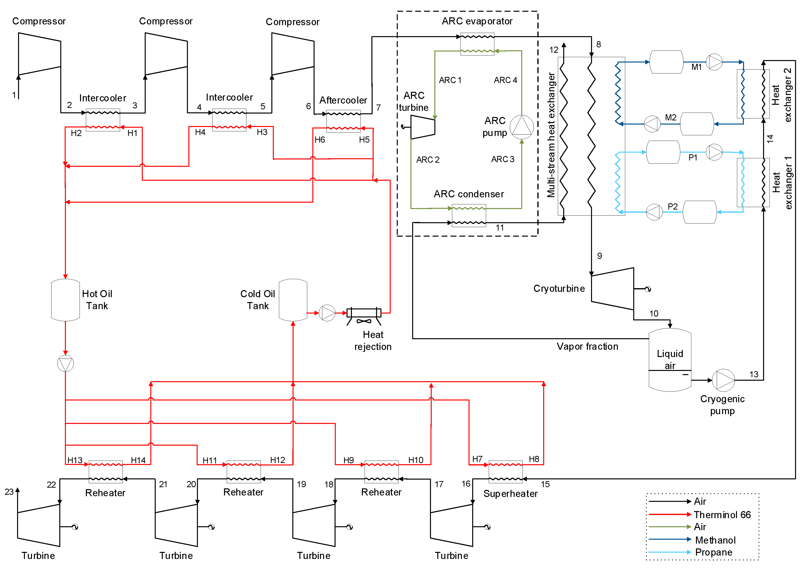
Figure 1 illustrates the scheme of the LAES that is proposed in this paper. The difference between the proposed scheme and the base case is the existence of the control volume that embodies the ARC unit indicated by the dashed line. The liquefaction process is based on Linde-Hampson cycle. Electricity is used to drive a three-stage intercooled compression train (1-7) while the waste heat from compressors intercoolers and aftercooler is stored and used later to increase the power turbines inlet temperature (H1-H6). The air leaving the compression train is cooled while transferring heat to the cryogenic ARC (7-8). The ARC generates power (ARC1-ARC2) and rejects heat (ARC2-ARC3) to the saturated vapor from the liquid air storage tank (vapor fraction-11). After being cooled in the ARC evaporator, the air (8-9) is further cooled in the multi-stream heat exchanger (cold box) by cold air from the ARC condenser (11-12), propane (P2-P1), and methanol (M2-M1). Finally, the air is expanded in a cryoturbine (9-10) and stored as liquid in the low-pressure tank at a cryogenic temperature. The air is selected as the Rankine cycle working fluid and Therminol 66 is selected as the thermal fluid for recovery and storage of inter- and aftercooler compression heat.
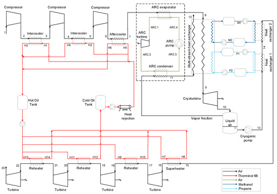
Figure 1.
Proposed scheme for the liquid air energy storage system.
During discharge process, liquid air is first pumped to a high pressure by the cryogenic pump (liquid air-13) and then it retrieves heat from propane (13-14) and methanol (14-15) as it flows through the two heat exchangers. Finally, the air is heated by the waste heat from compression and expands in the four-stage expansion train (16-23) generating electricity back to the grid.
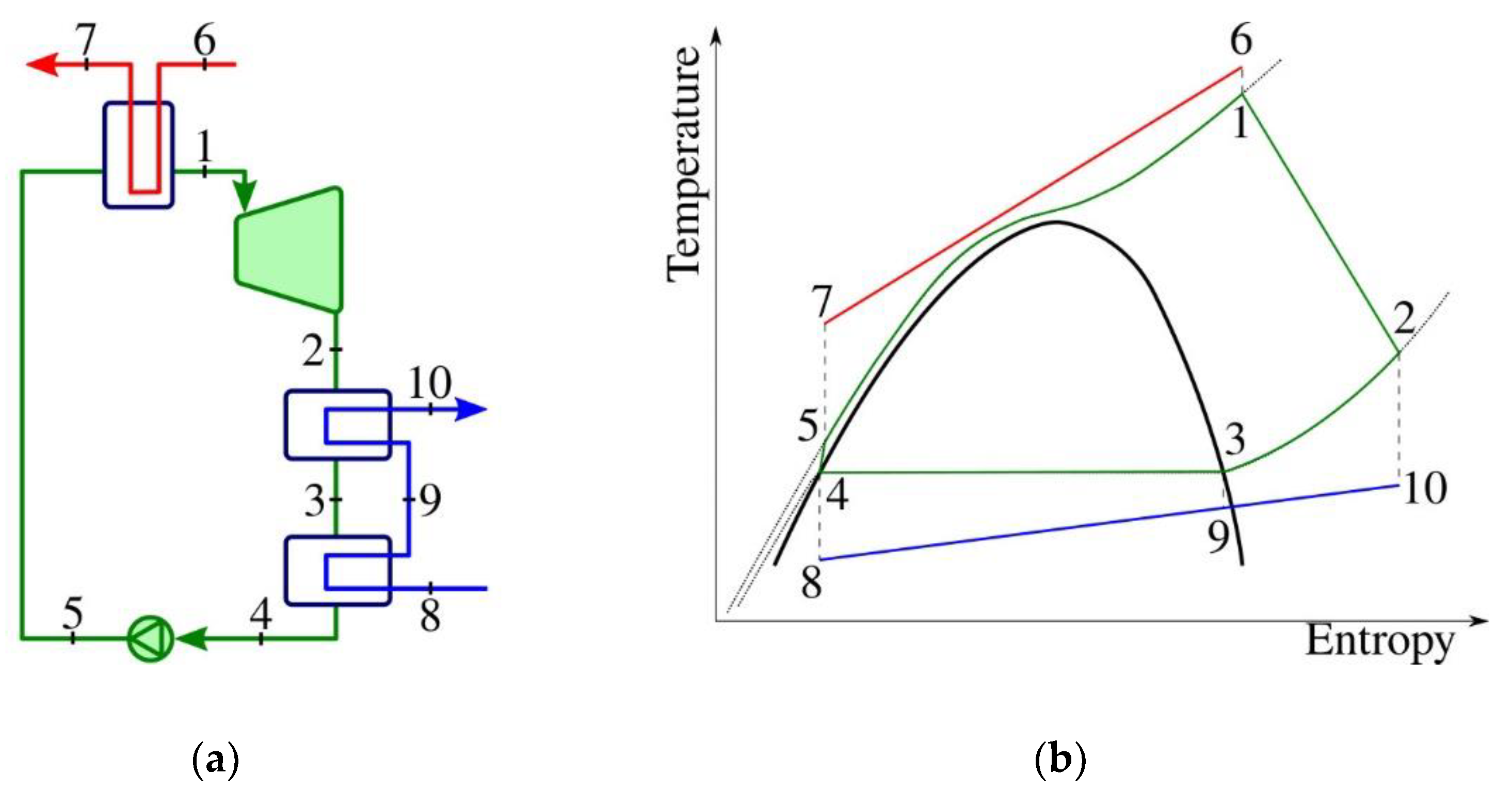
The ARC is a Rankine cycle, using air as a working fluid. It is possible to condensate air due to the low temperature streams that are available in LAES plant. The structure that was chosen for the ARC is supercritical as described in Figure 2 and Vilasboas et al. [47]. In this structure, the air is evaporated by the heat source (stream 6-7 in Figure 2 and stream 7-8 in Figure 1), enters the expander to generate power, leaves the expander as superheated fluid, and then it is de-superheated and condensed by stream 8-10 in Figure 2 (vapor fraction—11 in Figure 1).

Figure 2.
Supercritical ARC (a) structure and (b) T-s diagram [47].
3. Methodology
The simulations were carried out using Aspen HYSYS v.10 software [48], with Peng-Robinson and CPA property packages used for air, methanol, and propane, respectively. The assumptions used were:
- Steady-state condition during liquefaction and discharge processes;
- Pressure and temperature losses are disregarded;
- Kinetic and potential energy variations are neglected;
- The minimum temperature difference between the streams for the cold box is set to 3 °C, while for intercoolers, aftercooler, heat exchangers 1 and 2, and reheaters it is set to 5 °C, as proposed in [32,44];
- Isentropic efficiencies for compressors, cryogenic pump and power turbines are set as 85%, while isentropic efficiency for cryoturbine is set as 75%, as proposed in [21,49].
3.1. ARC Modeling and Optimization
Potential and kinetic energy variations and the pressure drop along the pipes and heat exchangers are neglected. Table 1 indicates the main parameters that were used for modeling the ARC. The thermodynamic properties for ARC are obtained by using REFPROP v.10 [50]. The turbine and pumps were modeled based on their isentropic efficiencies; heat exchangers obey the energy balance between their hot and cold sides.

Table 1.
Optimal ARC specifications.
ARC optimization is carried out using a jMetalPy [51] genetic algorithm (GA), adopting the maximization of efficiency as objective function. Turbine inlet temperature and evaporation and condensation pressures are the decision variables; their lower and upper bounds are showed in Table 2. Furthermore, a minimum temperature difference of 5 °C in the ARC evaporator and condenser and a minimum working fluid quality during expansion of 0.8 are imposed as optimization constraints.
Table 2.
ARC optimization decision variables and their lower and upper bounds.
3.2. Thermodynamic (Exergy) Analysis and Efficiencies
The round-trip energy/exergy efficiency (since it is an electricity-to-electricity plant both energy and exergy efficiencies generate the same result.) of the LAES system was calculated using Equation (1) in which: WPT is the power generation of power turbines; WCryopump is the power that is consumed by cryogenic pump; Wcomp is the power that is consumed by air compressors; WARC is the net power that is produced by the ARC; and WCT is the power that is generated by cryoturbine.
For the cryogenic ARC system, the energy efficiency can be expressed as follows, in which Qh is the heat that is transferred from the compressed air (streams 7-8), Equation (2).
Volumetric energy density (VED) is also an important parameter to evaluate the performance of LAES system and is defined as the ratio of the electricity that is generated to the liquid air storage volume, Equation (3).
Exergy analysis is used to assess the system performance and to indicate the amount of exergy destruction in each component, revealing space for improvement. Thus, Equation (4) is used for the ARC exergy efficiency. In this equation, BQh is the exergy of the heat that is supplied to the ARC which is calculated using Equation (5), where TH and TC are the thermodynamic mean temperatures in which the heat is supplied and retrieved from ARC, i.e., TH = ∆h/∆s.
The specific physical exergy (bph) is calculated by using the enthalpy and the entropy of each stream in actual and reference conditions (T0 = 298.15 K and P0 = 101.325 kPa), Equation (6).
bph = (h − href) − T0(s − sref)
Equation (7) is used to calculate the specific chemical exergy (bch) of the streams. It arises from the differences in chemical composition between the substances that are involved in the LAES and the species in the environment; bi st and yi denote, respectively, the standard chemical exergy and the mole fraction of each component in the mixture. Since no change in the composition of thermal oil, air of Rankine cycle, propane, and methanol occurs throughout their cycles, their chemical exergy does not influence the analysis and were disregarded. The standard chemical exergy of air components is taken from Szargut et al. [52].
The total specific exergy can be calculated by summing the physical and chemical components of each stream, Equation (8).
btotal = bph + bch
The exergy balance is then indicated by Equation (9), in which Sgen is the entropy generation and the second term of right-hand side corresponds to the exergy destruction.
3.3. Economic Analysis
An economic analysis is conducted to show the economic feasibility of the new configuration that is proposed. The investment cost for all the components follows Bejan et al. [53], Equation (10). In this equation, Z denotes the equipment purchase cost, Zref is the reference cost that is used in the cost estimation model, and CEPCI denotes the chemical engineering plant cost index which is used to take inflation into account (CEPCI2021 = 699.7 [54]).
In addition, a lifetime cost analysis is evaluated by calculating the levelized cost of storage (LCOS), as given in Equation (11). This method indicates the cost per unit of stored electricity depending on the system size, the system configuration, as well as the operation of the system. The LCOS is defined as the ratio between the total lifetime cost of an electricity storage technology by the cumulative electricity that is delivered. The values are brought to present using an interest rate (i).
CAPEX is capital investment cost, OPEX is operation and maintenance cost, Ec is the electricity cost, n is operating year, and Edelivered is yearly generated electricity. Table 3 indicates the assumptions that were used for calculating the LCOS in both plants.
Table 3.
Economic estimation data for calculating LCOS.
4. Results and Discussion
The results show a round-trip energy/exergy efficiency of 54.1% for the base case LAES system, with an electricity consumption per kg of liquid air of 0.217 kWh/kgair. The use of ARC increases liquid air yield comparison with the base case since the ARC decreases the temperature of the air entering in the multi-stream heat exchanger. Also, the round-trip energy/exergy efficiency increased in 5.6% to 57.1%. It is also possible to note that the electricity consumption per kg of liquid air during the liquefaction process dropped from 0.217 to 0.206 kWh/kgair and the liquid air yield increased from 86.0% to 90.7% of the compressed air mass flow rate. The thermodynamic properties of each stream of the new configuration are presented in Table A1.
Regarding the results from ARC optimization, this system presented a mass flow rate of 0.1 kg per kg of stream 8 (heat source), a condensing pressure of approximately 3 MPa and an evaporating pressure of 6 MPa. This system produces 2.4 kW during LAES charging while retrieving 18 kW of heat from LAES compressed air, thus presenting an energy and exergy efficiency of 13.2% and 33.7%, respectively. It is important to note that both effects, i.e., net energy that is retrieved from the compressed air and the electricity that is produced, are positive for LAES.
4.1. Parametric Analysis
The proposed configuration was tested by varying the compression outlet, pump outlet, and storage pressures.
4.1.1. Compression Outlet Pressure
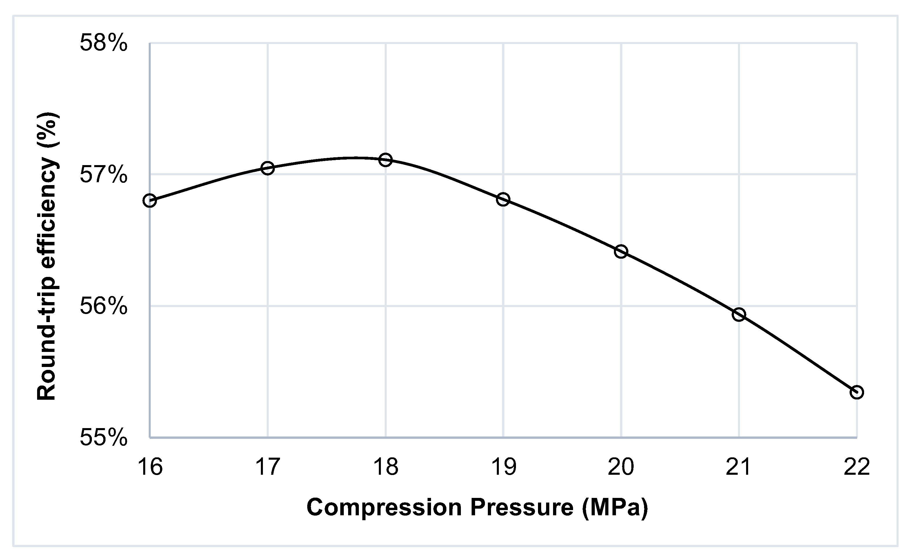
The compression outlet pressure was varied from 16 to 22 MPa while the cryogenic pump outlet pressure (8 MPa) and storage pressure (0.1 MPa) were kept constant. Figure 3 shows the influence of compression outlet pressure on the LAES performance. The round-trip energy/exergy efficiency increases with the increase of compression pressure to a maximum of 57.1% at 18 MPa. Increasing the compressor outlet pressure allows large expansion in the cryo-turbine, increasing the liquid yield in the tank, consequently, increasing the round-trip energy/exergy efficiency. Above 18 MPa, however, the pressure increment effect on the liquid yield is not sufficient to compensate for the increment in the compressors power consumption.
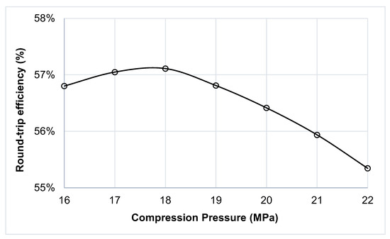
Figure 3.
Round-trip energy/exergy efficiency for different compression outlet pressures.
4.1.2. Pump Outlet Pressure
Figure 4 shows the effect of the pump outlet pressure variation (5 to 8.5 MPa) on the LAES performance keeping storage pressure at 0.1 MPa and compression outlet pressure at 18 MPa. An increment in the pump pressure leads to an increment in the net output power and in the round-trip energy/exergy efficiency. Since the pump work consumption is a fraction of the power turbine output, one can conclude that the highest possible pump outlet pressure should be used in the LAES plant. However, at pressures above 8.5 MPa, the temperature of the air increases to a point at which it is not possible to operate the cold box satisfactorily.
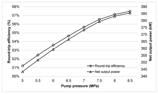
Figure 4.
Round-trip energy/exergy efficiency and net output power of electricity generation process for different pump pressures.
4.1.3. Storage Pressure
Figure 5 shows the effect of the storage pressure on the LAES performance and volumetric energy density while compression and pump outlet pressures are maintained at 18 and 8 MPa, respectively. It can be observed that the round-trip efficiency of the proposed system increases from 57.1% to 57.9% when the storage pressure increases from 0.1 to 2.1 MPa. This is mainly due to an increased liquid air production. For storage pressures that are greater than 2.1 MPa, the air can be completely liquified and the proposed configuration, which uses the vapor fraction for heat exchanging, would not be appliable. On the other hand, the volumetric energy density gradually decreases from 102.7 to 73.5 kWh/m3 when the storage pressure increases. It can be explained by the increase in temperature which offsets the effect of pressure on density of the stored air as previously indicated in [57]. Thus, there is a clear trade-off between the efficiency and energy density that has to be taken into consideration.
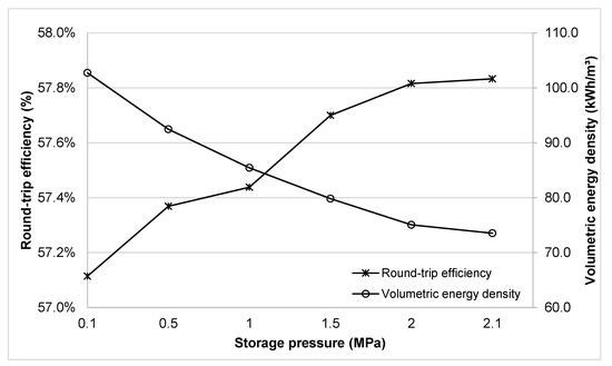
Figure 5.
Round-trip energy/exergy efficiency and volumetric energy density for different storage pressures.
4.2. Exergy Analysis
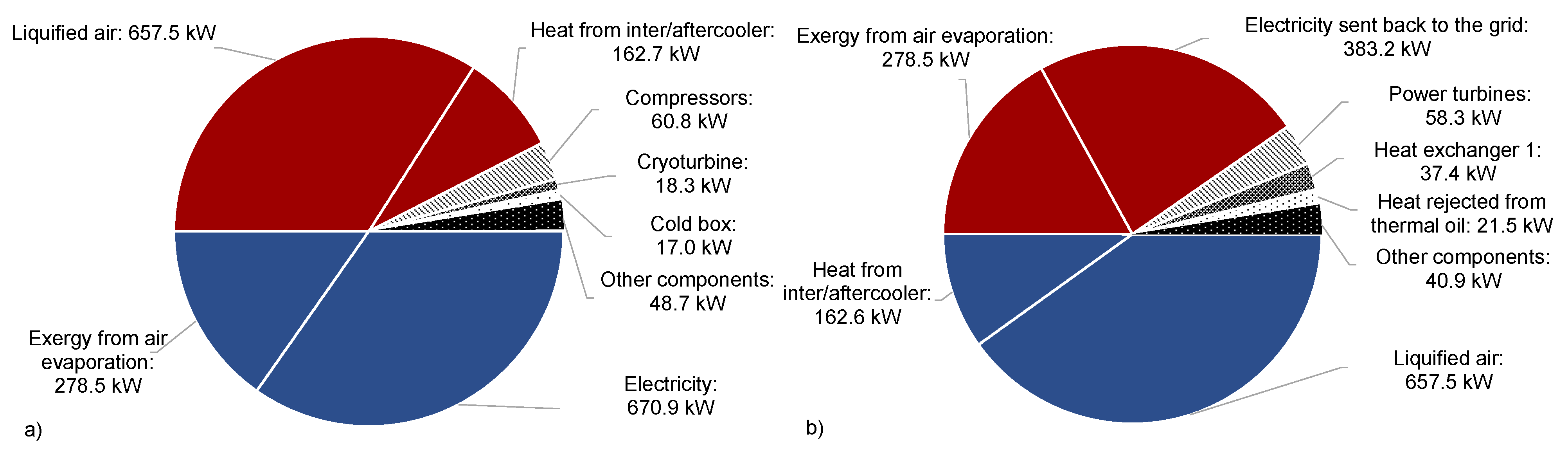
The exergy that is consumed for the liquefaction of air comes from the grid (electricity to be stored) and from the exergy that is generated during regasification and stored in propane, methanol, and cold oil tanks (in blue). On the other hand, the products of liquefaction are the exergy in liquid air and in hot oil (in red), which are consumed during regasification to generate electricity and “cold” exergy and electricity.
In respect to the base case, the highest share of internal exergy destruction corresponds to compressors, 19.7%, and power turbines, 17.9%, as can be observed in Figure 6. To avoid this irreversibility, more efficient compressors and turbines have to be used, which can be achieved by adding more intercooling and reheating stages, respectively. The multi-stream heat exchanger (cold box) is the third largest component in terms of exergy destruction in the base case. A reduction of this irreversibility can be envisaged by a better temperature match among the streams, which does not necessarily imply higher specific costs. The heat exchanger 1 also has a significant share of exergy destruction (13.6%). This happens due to the large temperature difference between propane and air, which could be reduced by increasing the cold energy storage steps, i.e., creating a smooth temperature reduction.
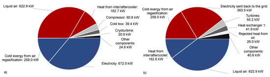
Figure 6.
Exergy input (blue), output (red), and exergy destruction (hatched) of the LAES (base case) for: (a) the liquefaction process and (b) the electricity generation process.
Regarding the LAES system with ARC, the highest share of internal exergy destruction also corresponds to compressors, 20.1%, and power turbines, 19.2%, as can be seen in Figure 7. The inclusion of the ARC, besides adding extra power, reduces the temperature difference in the multi-stream heat exchanger generating a significant reduction in the exergy that is destroyed in this component (39.4 to 17.0 kW), leading to a higher mass flow rate of liquid air that is stored (0.86 to 0.91 kg/s).
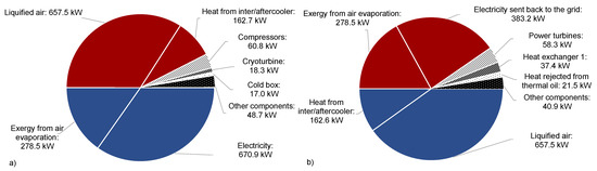
Figure 7.
Exergy input (blue), output (red), and exergy destruction (hatched) of the LAES system with ARC for: (a) the liquefaction process and (b) the electricity generation process.
Table 4 compares the internal and external exergy destruction of each component of the base case and proposed LAES system. The overall exergy destruction is reduced by 6 kW by the inclusion of the ARC while the round-trip efficiency increases 3.0 percentual points.
Table 4.
Internal and external exergy destruction of each component of base case and the proposed LAES + ARC configuration.
4.3. Economic Analysis
The economic analysis was conducted to demonstrate the economic feasibility of the proposed system in comparison to the base case. The equipment cost functions for each component are listed in Table A2. The basic equipment parameters, such as area, volume, and power, were retrieved from Aspen HYSYS® software. The investment cost of the new configuration increases by US$ 60,464.42 compared to the base case. The difference between these two systems lies on the addition of the ARC and on sizing, since a larger yield of liquid air is produced. Even though there is an increase in the investment cost, the economic analysis shows a lower LCOS, i.e., 185.48 $/kWh for the proposed case in comparison to 188.62 $/kWh for the base case. The additional capital and operational cost that is introduced with the ARC is offset by the increase in the round-trip efficiency.
5. Conclusions
A new configuration is proposed for LAES systems aiming to contribute to an efficiency increase without increasing LCOS. A parametric study was carried out to define the proper compression, storage, and liquid air pumping pressures. The proposed configuration uses an air Rakine cycle (ARC) to reduce the exergy destruction during heat-exchanging while generating extra power, thus improving the LAES liquefaction efficiency. The cryogenic ARC decreased the inlet temperature of the multi-stream heat exchanger, increasing the liquid air yield from 86.0% to 90.7%. This effect was revealed to be more significant for LAES overall round-trip efficiency than the power that is produced by the ARC itself. The proposed system can achieve a round-trip efficiency of 57.1% which is approximately 6% higher than the base case. The results that were obtained from the exergy analysis show that the overall exergy destruction is reduced by 6 kW in the new configuration. Although the compressors and power turbines are still the components with the highest exergy destruction, the addition of the cryogenic ARC contributed to a decrease of the exergy destruction in the multi-stream heat exchanger from 39.4 to 17.0 kW. The economic analysis revealed that the ARC added US$ 60,464.42 to LAES CAPEX. However, the new configuration seems to be competitive despite the increment in the investment cost since the LCOS was reduced by almost 2%. Further development and scale increase in the production of ORCs, which are similar to ARCs, may alleviate the increment in the total acquisition cost. Nevertheless, the equipment that is responsible for the highest costs are compressors (41.3%) and thermal storage tanks (26.5%) which are already mature technologies without clear space for improvements. Thus, the high acquisition cost that is required seems to keep LAES as solution for large systems only.
Author Contributions
Conceptualization, M.V.P.M. and J.A.M.d.S.; methodology, M.V.P.M. and J.A.M.d.S.; software, M.V.P.M., I.F.V., and J.A.M.d.S.; validation, M.V.P.M., I.F.V., and J.A.M.d.S.; formal analysis, M.V.P.M. and J.A.M.d.S.; investigation, M.V.P.M. and J.A.M.d.S.; resources, M.V.P.M. and J.A.M.d.S.; data curation, M.V.P.M.; writing—original draft preparation, M.V.P.M.; writing—review and editing, M.V.P.M. and J.A.M.d.S.; supervision, J.A.M.d.S.; project administration, J.A.M.d.S.; funding acquisition, J.A.M.d.S. All authors have read and agreed to the published version of the manuscript.
Funding
This research was funded by Grupo Global Participações em Energia (GPE) grant number PD-06961-0011/2019 and the Coordination for the Improvement of Higher Education Personnel (CAPES).
Institutional Review Board Statement
Not applicable.
Informed Consent Statement
Not applicable.
Data Availability Statement
Not applicable.
Acknowledgments
The authors would like to thank the Coordination for the Improvement of Higher Education Personnel (CAPES) and Global Participações em Energia under ANEEL P&D program project number PD-06961-0011/2019 for the financial support.
Conflicts of Interest
The authors declare no conflict of interest.
Appendix A
Table A1.
Thermodynamic properties that were obtained for the streams that are indicated in Figure 1.
Table A1.
Thermodynamic properties that were obtained for the streams that are indicated in Figure 1.
| Stream | Fluid | m (kg/s) | %vN2 | T (°C) | P (kPa) | h (kJ/kg) | s (kJ/kg-K) | Btotal (kW) |
|---|---|---|---|---|---|---|---|---|
| 1 | Air | 1.0 | 79 | 25.0 | 101.3 | −0.3 | 5.3 | 0.0 |
| 2 | Air | 1.0 | 79 | 242.6 | 569.6 | 224.6 | 5.3 | 204.8 |
| 3 | Air | 1.0 | 79 | 30.0 | 569.6 | 3.5 | 4.8 | 148.2 |
| Oil 1 | Therminol 66 | 0.7 | - | 25.0 | 101.3 | −88.6 | −0.7 | 0.0 |
| Oil 2 | Therminol 66 | 0.7 | - | 202.9 | 101.3 | 227.3 | 0.1 | 50.4 |
| 4 | Air | 1.0 | 79 | 251.5 | 3202.0 | 232.7 | 4.8 | 357.2 |
| 5 | Air | 1.0 | 79 | 30.0 | 3202.0 | −3.2 | 4.3 | 295.4 |
| Oil 3 | Therminol 66 | 0.7 | - | 25.0 | 101.3 | −88.6 | −0.7 | 0.0 |
| Oil 4 | Therminol 66 | 0.7 | - | 206.3 | 101.3 | 234.5 | 0.1 | 54.5 |
| 6 | Air | 1.0 | 79 | 253.2 | 18,000.0 | 230.5 | 4.3 | 508.7 |
| 7 | Air | 1.0 | 79 | 30.0 | 18,000.0 | −30.3 | 3.7 | 441.0 |
| Oil 5 | Therminol 66 | 0.9 | - | 25.0 | 101.3 | −76.5 | −0.7 | 0.0 |
| Oil 6 | Therminol 66 | 0.9 | - | 196.3 | 101.3 | 213.5 | 0.1 | 57.7 |
| 8 | Air | 1.0 | 79 | 16.1 | 18,000.0 | −48.1 | 3.6 | 441.2 |
| 9 | Air | 1.0 | 79 | −181.3 | 18,000.0 | −386.8 | 1.6 | 707.6 |
| M1 | Methanol | 0.7 | - | 12.0 | 101.3 | −7484.2 | 0.7 | 0.4 |
| M2 | Methanol | 0.7 | - | −59.9 | 101.3 | −7616.7 | 0.2 | 17.5 |
| P1 | Propane | 1.1 | - | −59.9 | 101.3 | −2923.2 | 1.3 | 167.6 |
| P2 | Propane | 1.1 | - | −184.5 | 101.3 | −3144.6 | −0.3 | 429.0 |
| 10 | Air | 1.0 | 79 | −194.2 | 101.3 | −401.3 | 1.6 | 674.8 |
| Vapor fraction | Air | 0.1 | 93 | −194.2 | 101.3 | −223.2 | 4.0 | 17.5 |
| 11 | Air | 0.1 | 93 | −150.8 | 101.3 | −179.2 | 4.4 | 9.3 |
| ARC 1 | Air | 0.1 | 79 | 25.0 | 6000.0 | −15.4 | 4.0 | 22.2 |
| ARC 2 | Air | 0.1 | 79 | −23.2 | 2993.5 | −59.8 | 4.1 | 18.7 |
| ARC 2′ | Air | 0.1 | 79 | −145.8 | 2993.5 | −237.4 | 3.0 | 27.4 |
| ARC 3 | Air | 0.1 | 79 | −146.5 | 2993.5 | −301.9 | 2.5 | 32.9 |
| ARC 4 | Air | 0.1 | 79 | −139.6 | 6000.0 | −294.8 | 2.5 | 33.1 |
| 12 | Air | 0.1 | 93 | −100.3 | 101.3 | −128.2 | 4.7 | 4.4 |
| Lair * | Air | 0.9 | 78 | −194.2 | 101.3 | −419.6 | 1.4 | 657.5 |
| 13 | Air | 0.9 | 78 | −190.8 | 8000.0 | −409.0 | 1.4 | 658.1 |
| 14 | Air | 0.9 | 78 | −68.8 | 8000.0 | −136.8 | 3.5 | 359.3 |
| 15 | Air | 0.9 | 78 | 7.0 | 8000.0 | −40.7 | 3.9 | 337.7 |
| 16 | Air | 0.9 | 78 | 195.0 | 8000.0 | 168.6 | 4.4 | 372.6 |
| Oil 7 | Therminol 66 | 0.6 | - | 201.5 | 101.3 | 224.4 | 0.1 | 40.6 |
| Oil 8 | Therminol 66 | 0.6 | - | 12.0 | 101.3 | −106.7 | −0.8 | 0.2 |
| 17 | Air | 0.9 | 78 | 88.9 | 2683.8 | 60.2 | 4.5 | 259.5 |
| 18 | Air | 0.9 | 78 | 196.5 | 2683.8 | 173.9 | 4.8 | 288.3 |
| Oil 9 | Therminol 66 | 0.6 | - | 201.5 | 101.3 | 224.4 | 0.1 | 40.6 |
| Oil 10 | Therminol 66 | 0.6 | - | 108.7 | 101.3 | 44.5 | −0.3 | 9.4 |
| 19 | Air | 0.9 | 78 | 91.2 | 900.3 | 65.6 | 4.8 | 175.6 |
| 20 | Air | 0.9 | 78 | 196.5 | 900.3 | 175.4 | 5.1 | 203.6 |
| Oil 11 | Therminol 66 | 0.6 | - | 201.5 | 101.3 | 224.4 | 0.1 | 40.6 |
| Oil 12 | Therminol 66 | 0.6 | - | 112.3 | 101.3 | 50.8 | −0.3 | 10.2 |
| 21 | Air | 0.9 | 78 | 91.7 | 302.0 | 67.2 | 5.1 | 90.9 |
| 22 | Air | 0.9 | 78 | 196.5 | 302.0 | 175.9 | 5.4 | 118.7 |
| Oil 13 | Therminol 66 | 0.6 | - | 201.5 | 101.3 | 224.4 | 0.1 | 40.6 |
| Oil 14 | Therminol 66 | 0.6 | - | 113.2 | 101.3 | 52.4 | −0.3 | 10.4 |
| Rejected cold air | Air | 0.9 | 78 | 91.8 | 101.3 | 67.7 | 5.5 | 6.1 |
| Liquid oil 1 | Therminol 66 | 2.3 | - | 201.5 | 101.3 | 224.4 | 0.1 | 162.6 |
| Liquid oil 2 | Therminol 66 | 2.3 | - | 88.8 | 101.3 | 10.3 | −0.4 | 21.8 |
* Lair means liquefied air.
Table A2.
Purchase cost estimation of equipment that was used in the proposed configuration [26,49,58,59,60].
Table A2.
Purchase cost estimation of equipment that was used in the proposed configuration [26,49,58,59,60].
| Equipment | Cost Estimation Model | Cost Year | CEPCIref [61] |
|---|---|---|---|
| Air compressors | Zref = 7900 | 2009 | 521.9 |
| Intercoolers | Zref = 12,000 | 2020 | 596.2 |
| Aftercooler | Zref = 12,000 | 2020 | 596.2 |
| ARC evaporator | Zref = 16,000 | 2020 | 596.2 |
| ARC condenser | Zref = 8000 | 2019 | 607.5 |
| ARC desuperheater | Zref = 12,000 | 2020 | 596.2 |
| ARC turbine | Zref = 1100 | 2017 | 567.5 |
| ARC pump | Zref = 483 | 2018 | 603.1 |
| Cold box | Zref = 32,800 | 2005 | 468.2 |
| Cryoturbine | Zref = 1100 | 2017 | 567.5 |
| Cryogenic Tank | Zref = 320 VLiquid air tank | 2013 | 567.3 |
| Cryopump | Zref f = 483 | 2018 | 603.1 |
| Heat exchanger 1 | Zref = 32,800 | 2005 | 468.2 |
| Heat exchanger 2 | Zref = 32,800 | 2005 | 468.2 |
| Methanol Tank | Zref = 572 VMethanol tank | 2018 | 603.1 |
| Propane Tank | Zref = 1326 VPropane tank | 2018 | 603.1 |
| Power turbines | Zref = 1100 | 2017 | 567.5 |
| Superheater | Zref = 16,000 | 2020 | 596.2 |
| Reheaters | Zref = 16,000 | 2020 | 596.2 |
| Hot oil tank | Zref = 423 VHot oil tank | 2018 | 603.1 |
| Cold oil tank | Zref = 423 VCold oil tank | 2018 | 603.1 |
| Mixer | Zref = 50 | 2019 | 607.5 |
| Thermal oil heat exchanger | Zref = 8000 | 2019 | 607.5 |
References
- International Energy Agency. Global Energy Review 2019; International Energy Agency: Paris, France, 2020. [Google Scholar]
- Aneke, M.; Wang, M. Energy storage technologies and real life applications—A state of the art review. Appl. Energy 2016, 179, 350–377. [Google Scholar] [CrossRef] [Green Version]
- Chen, H.; Cong, T.N.; Yang, W.; Tan, C.; Li, Y.; Ding, Y. Progress in electrical energy storage system: A critical review. Prog. Nat. Sci. 2009, 19, 291–312. [Google Scholar] [CrossRef]
- Lin, B.; Wu, W.; Bai, M.; Xie, C. Liquid air energy storage: Price arbitrage operations and sizing optimization in the GB real-time electricity market. Energy Econ. 2019, 78, 647–655. [Google Scholar] [CrossRef]
- Frate, G.F.; Ferrari, L.; Desideri, U. Energy storage for grid-scale applications: Technology review and economic feasibility analysis. Renew. Energy 2021, 163, 1754–1772. [Google Scholar] [CrossRef]
- Popov, D.; Fikiin, K.; Stankov, B.; Alvarez, G.; Youbi-Idrissi, M.; Damas, A.; Evans, J.; Brown, T. Cryogenic Heat Exchangers for Process Cooling and Renewable Energy Storage: A Review. Appl. Therm. Eng. 2019, 153, 275–290. [Google Scholar] [CrossRef]
- Borri, E.; Tafone, A.; Romagnoli, A.; Comodi, G. A review on liquid air energy storage: History, state of the art and recent developments. Renew. Sustain. Energy Rev. 2021, 137, 110572. [Google Scholar] [CrossRef]
- Morgan, R.; Nelmes, S.; Gibson, E.; Brett, G. An analysis of a large-scale liquid air energy storage system 1. In Proceedings of the ICE Proceedings, Coimbatore, India, 3 March 2015; pp. 1–10. [Google Scholar]
- Morgan, R.; Nelmes, S.; Gibson, E.; Brett, G. Liquid air energy storage—Analysis and first results from a pilot scale demonstration plant. Appl. Energy 2015, 137, 845–853. [Google Scholar] [CrossRef]
- Callaghan, O.O.; Donnellan, P. Liquid air energy storage systems: A review. Renew. Sustain. Energy Rev. 2021, 146, 111113. [Google Scholar] [CrossRef]
- An, B.; Chen, J.; Deng, Z.; Zhang, T.; Wang, J.; Yang, L.; Wang, J.; Chen, E.J.; Wang, J. Design and testing of a high performance liquid phase cold storage system for liquid air energy storage. Energy Convers. Manag. 2020, 226, 113520. [Google Scholar] [CrossRef]
- Krawczyk, P.; Szabłowski, Ł.; Karellas, S.; Kakaras, E.; Badyda, K. Comparative thermodynamic analysis of compressed air and liquid air energy storage systems. Energy 2018, 142, 46–54. [Google Scholar] [CrossRef]
- Vecchi, A.; Li, Y.; Ding, Y.; Mancarella, P.; Sciacovelli, A. Liquid air energy storage (LAES): A review on technology state-of-the-art, integration pathways and future perspectives. Adv. Appl. Energy 2021, 3, 100047. [Google Scholar] [CrossRef]
- Sciacovelli, A.; Vecchi, A.; Ding, Y. Liquid air energy storage (LAES) with packed bed cold thermal storage – From component to system level performance through dynamic modelling. Appl. Energy 2017, 190, 84–98. [Google Scholar] [CrossRef] [Green Version]
- Liu, Z.; Kim, D.; Gundersen, T. Optimal recovery of thermal energy in liquid air energy storage. Energy 2021, 240, 122810. [Google Scholar] [CrossRef]
- Hüttermann, L.; Span, R.; Maas, P.; Scherer, V. Investigation of a liquid air energy storage (LAES) system with different cryogenic heat storage devices. Energy Procedia 2019, 158, 4410–4415. [Google Scholar] [CrossRef]
- Hüttermann, L.; Span, R. Influence of the Heat Capacity of the Storage Material on the Efficiency of Thermal Regenerators in Liquid Air Energy Storage Systems. Energy 2019, 174, 236–245. [Google Scholar] [CrossRef]
- Chen, J.; An, B.; Yang, L.; Wang, J.; Hu, J. Construction and optimization of the cold storage process based on phase change materials used for liquid air energy storage system. J. Energy Storage 2021, 41, 102873. [Google Scholar] [CrossRef]
- Tafone, A.; Borri, E.; Cabeza, L.F.; Romagnoli, A. Innovative cryogenic Phase Change Material (PCM) based cold thermal energy storage for Liquid Air Energy Storage (LAES)—Numerical dynamic modelling and experimental study of a packed bed unit. Appl. Energy 2021, 301, 117417. [Google Scholar] [CrossRef]
- Guo, L.; Ji, W.; Gao, Z.; Fan, X.; Wang, J. Dynamic characteristics analysis of the cold energy transfer in the liquid air energy storage system based on different modes of packed bed. J. Energy Storage 2021, 40, 102712. [Google Scholar] [CrossRef]
- Guizzi, G.L.; Manno, M.; Tolomei, L.M.; Vitali, R.M. Thermodynamic analysis of a liquid air energy storage system. Energy 2015, 93, 1639–1647. [Google Scholar] [CrossRef] [Green Version]
- Li, X.; Lv, C.; Yang, S.; Li, J.; Deng, B.; Li, Q. Preliminary design and performance analysis of a radial inflow turbine for a large-scale helium cryogenic system. Energy 2019, 167, 106–116. [Google Scholar] [CrossRef]
- Xue, X.D.; Wang, S.X.; Zhang, X.L.; Cui, C.; Chen, L.B.; Zhou, Y.; Wang, J.J. Thermodynamic Analysis of a Novel Liquid Air Energy Storage System. Phys. Procedia 2015, 67, 733–738. [Google Scholar] [CrossRef] [Green Version]
- Tafone, A.; Romagnoli, A.; Borri, E.; Comodi, G. New parametric performance maps for a novel sizing and selection methodology of a Liquid Air Energy Storage system. Appl. Energy 2019, 250, 1641–1656. [Google Scholar] [CrossRef]
- Fan, X.; Gao, Z.; Ji, W.; Guo, L.; Lin, W.; Wang, J. Thermodynamic optimization with multi objectives and parameters for liquid air energy storage system based on the particle swarm optimization (PSO). J. Energy Storage 2021, 41, 102878. [Google Scholar] [CrossRef]
- Wu, S.; Zhou, C.; Doroodchi, E.; Moghtaderi, B. Techno-economic analysis of an integrated liquid air and thermochemical energy storage system. Energy Convers. Manag. 2020, 205, 112341. [Google Scholar] [CrossRef]
- Gao, Z.; Ji, W.; Guo, L.; Fan, X.; Wang, J. Thermo-economic analysis of the integrated bidirectional peak shaving system consisted by liquid air energy storage and combined cycle power plant. Energy Convers. Manag. 2021, 234, 113945. [Google Scholar] [CrossRef]
- Ji, W.; Zhou, Y.; Zhang, W.; Pan, C.Z.; Wang, J.J. Thermodynamic characteristics of a novel wind- solar-liquid air energy storage system. IOP Conf. Ser. Mater. Sci. Eng. 2017, 278, 012070. [Google Scholar] [CrossRef]
- Kantharaj, B.; Garvey, S.; Pimm, A. Compressed air energy storage with liquid air capacity extension. Appl. Energy 2015, 157, 152–164. [Google Scholar] [CrossRef]
- Li, Y.; Cao, H.; Wang, S.; Jin, Y.; Li, D.; Wang, X.; Ding, Y. Load shifting of nuclear power plants using cryogenic energy storage technology. Appl. Energy 2014, 113, 1710–1716. [Google Scholar] [CrossRef]
- Cetin, T.H.; Kanoglu, M.; Yanikomer, N. Cryogenic energy storage powered by geothermal energy. Geothermics 2019, 77, 34–40. [Google Scholar] [CrossRef]
- He, T.; Lv, H.; Shao, Z.; Zhang, J.; Xing, X.; Ma, H. Cascade utilization of LNG cold energy by integrating cryogenic energy storage, organic Rankine cycle and direct cooling. Appl. Energy 2020, 277, 115570. [Google Scholar] [CrossRef]
- Park, J.; You, F.; Mun, H.; Lee, I. Liquefied natural gas supply chain using liquid air as a cold carrier: Novel method for energy recovery. Energy Convers. Manag. 2021, 227, 14. [Google Scholar] [CrossRef]
- Tafone, A.; Borri, E.; Comodi, G.; van den Broek, M.; Romagnoli, A. Liquid Air Energy Storage performance enhancement by means of Organic Rankine Cycle and Absorption Chiller. Appl. Energy 2018, 228, 1810–1821. [Google Scholar] [CrossRef]
- Peng, X.; She, X.; Cong, L.; Zhang, T.; Li, C.; Li, Y.; Wang, L.; Tong, L.; Ding, Y. Thermodynamic study on the effect of cold and heat recovery on performance of liquid air energy storage. Appl. Energy 2018, 221, 86–99. [Google Scholar] [CrossRef]
- She, X.; Peng, X.; Nie, B.; Leng, G.; Zhang, X.; Weng, L.; Tong, L.; Zheng, L.; Wang, L.; Ding, Y. Enhancement of round trip efficiency of liquid air energy storage through effective utilization of heat of compression. Appl. Energy 2017, 206, 1632–1642. [Google Scholar] [CrossRef]
- Xue, X.D.; Zhang, T.; Zhang, X.L.; Ma, L.-R.; He, Y.-L.; Li, M.-J.; Mei, S.W. Performance evaluation and exergy analysis of a novel combined cooling, heating and power (CCHP) system based on liquid air energy storage. Energy 2021, 222, 13. [Google Scholar] [CrossRef]
- Zhang, T.; Zhang, X.L.; He, Y.L.; Xue, X.D.; Mei, S.W. Thermodynamic analysis of hybrid liquid air energy storage systems based on cascaded storage and effective utilization of compression heat. Appl. Therm. Eng. 2020, 164, 114526. [Google Scholar] [CrossRef]
- Hamdy, S.; Morosuk, T.; Tsatsaronis, G. Cryogenics-based energy storage: Evaluation of cold exergy recovery cycles. Energy 2017, 138, 1069–1080. [Google Scholar] [CrossRef]
- Cetin, T.H.; Kanoglu, M.; Bedir, F. Integration of cryogenic energy storage and cryogenic organic cycle to geothermal power plants. Geothermics 2020, 87, 101830. [Google Scholar] [CrossRef]
- Antonelli, M.; Barsali, S.; Desideri, U.; Giglioli, R.; Paganucci, F.; Pasini, G. Liquid air energy storage: Potential and challenges of hybrid power plants. Appl. Energy 2017, 194, 522–529. [Google Scholar] [CrossRef]
- Abdon, A.; Zhang, X.; Parra, D.; Patel, M.K.; Bauer, C.; Worlitschek, J. Techno-economic and environmental assessment of stationary electricity storage technologies for different time scales. Energy 2017, 139, 1173–1187. [Google Scholar] [CrossRef]
- Jülch, V. Comparison of electricity storage options using levelized cost of storage (LCOS) method. Appl. Energy 2016, 183, 1594–1606. [Google Scholar] [CrossRef]
- Tafone, A.; Ding, Y.; Li, Y.; Xie, C.; Romagnoli, A.; Trip, R. Levelised Cost of Storage (LCOS) analysis of liquid air energy storage system integrated with Organic Rankine Cycle. Energy 2020, 198, 117275. [Google Scholar] [CrossRef]
- Hamdy, S.; Morosuk, T.; Tsatsaronis, G. Exergetic and economic assessment of integrated cryogenic energy storage systems. Cryogenics 2019, 99, 39–50. [Google Scholar] [CrossRef]
- Xie, C.; Hong, Y.; Ding, Y.; Li, Y.; Radcliffe, J. An economic feasibility assessment of decoupled energy storage in the UK: With liquid air energy storage as a case study. Appl. Energy 2018, 225, 244–257. [Google Scholar] [CrossRef]
- Vilasboas, I.F.; Gabriel, V.; Fagundes, S.; Armando, S.; Ribeiro, J.; Augusto, J. Surrogate Models Applied to Optimized Organic Rankine Cycles. Energies 2021, 14, 8456. [Google Scholar] [CrossRef]
- AspenTech Aspen HYSYS, v.10 2017; Aspen Technology Inc.: Bedford, MA, USA, 2017.
- Hossein, M.; Zeynalian, M.; Reza, A.; Arabkoohsar, A.; Soltani, M. Energy, exergy, and economic analyses of an innovative energy storage system; liquid air energy storage (LAES) combined with high-temperature thermal energy storage (HTES). Energy Convers. Manag. 2020, 226, 113486. [Google Scholar] [CrossRef]
- Lemmon, E.W.; Bell, I.H.; Huber, M.L.; McLinden, O. NIST Standard Reference Database 23: Reference Fluid Thermodynamic and Transport Properties-REFPROP 2018; National Institute of Standard and Technology: Gaithersburg, MD, USA, 2018. [Google Scholar]
- Benítez-hidalgo, A.; Nebro, A.J.; García-nieto, J.; Oregi, I.; Del, J. jMetalPy: A Python framework for multi-objective optimization with metaheuristics. Swarm Evol. Comput. 2019, 51, 100598. [Google Scholar] [CrossRef] [Green Version]
- Szargut, J.; Morris, D.R.; Stewart, F.R. Exergy Analysis of Thermal, Chemical, and Metallurgical Processes; Hemisphere Publishing Corporation: New York, NY, USA, 1988. [Google Scholar]
- Bejan, A.; Tsatsaronis, G.; Moran, M. Thermal Design and Optimization, 7th ed.; John Wiley & Sons: Hoboken, NJ, USA, 1996. [Google Scholar]
- Junsittiwate, R.; Srinophakun, T.R.; Sukpancharoen, S. Techno-economic, environmental, and heat integration of palm empty fruit bunch upgrading for power generation. Energy Sustain. Dev. 2022, 66, 140–150. [Google Scholar] [CrossRef]
- Discount Rate. Available online: http://people.stern.nyu.edu/adamodar/New_Home_Page/datacurrent.html#discrate (accessed on 5 February 2022).
- Electricity Prices. Available online: https://pt.globalpetrolprices.com/electricity_prices/ (accessed on 5 February 2022).
- Wang, C.; Cui, Q.; Dai, Z.; Zhang, X.; Xue, L.; You, Z.; She, X. Performance analysis of liquid air energy storage with enhanced cold storage density for combined heating and power generation. J. Energy Storage 2022, 46, 103836. [Google Scholar] [CrossRef]
- Hossein, M.; Saharkhiz, M.; Ghorbani, B.; Ebrahimi, A. Exergy, economic and pinch analyses of a novel integrated structure for cryogenic energy storage and freshwater production using ejector refrigeration cycle, desalination unit, and natural gas combustion plant. J. Energy Storage 2021, 44, 103471. [Google Scholar] [CrossRef]
- Sadeghi, S.; Ghandehariun, S.; Naterer, G.F. Exergoeconomic and multi-objective optimization of a solar thermochemical hydrogen production plant with heat recovery. Energy Convers. Manag. 2020, 225, 113441. [Google Scholar] [CrossRef]
- Nabat, M.H.; Soltani, M.; Razmi, A.R.; Nathwani, J.; Dusseault, M.B. Investigation of a green energy storage system based on liquid air energy storage (LAES) and high-temperature concentrated solar power (CSP): Energy, exergy, economic, and environmental (4E) assessments, along with a case study for San Diego, US. Sustain. Cities Soc. 2021, 75, 103305. [Google Scholar] [CrossRef]
- Economic Indicators: CEPCI. Available online: https://www.chemengonline.com/pci-home (accessed on 27 January 2022).


Publisher’s Note: MDPI stays neutral with regard to jurisdictional claims in published maps and institutional affiliations. |
© 2022 by the authors. Licensee MDPI, Basel, Switzerland. This article is an open access article distributed under the terms and conditions of the Creative Commons Attribution (CC BY) license (https://creativecommons.org/licenses/by/4.0/).