Article

A Novel Polarity Correction Method Developed on Cross Correlation Analysis for Downhole Migration-Based Location of Microseismic Events

1
Key Laboratory of Exploration Technologies for Oil and Gas Resources, Ministry of Education, Yangtze University, Wuhan 430100, China
2
Cooperative Innovation Center of Unconventional Oil and Gas (Ministry of Education & Hubei Province), Yangtze University, Wuhan 430100, China
3
Department of Earth Sciences, Quaid-i-Azam University, Islamabad 45320, Pakistan
4
Hubei Subsurface Multi-Scale Imaging Key Laboratory, Institute of Geophysics and Geomatics, China University of Geosciences, Wuhan 430074, China
*
Author to whom correspondence should be addressed.
Energies 2022, 15(8), 2772; https://doi.org/10.3390/en15082772
Submission received: 27 February 2022 / Revised: 28 March 2022 / Accepted: 4 April 2022 / Published: 9 April 2022

Abstract

:
Migration-based approaches depending on waveform stacking are generally used to locate the microseismic events in hydro-fracturing monitoring. A simple waveform stacking with polarity correction normally provides better results than any of the absolute value-based methods. However, the existing polarity estimation method based on cross correlation analysis selects only individual waveform as a reference waveform, which may affect the precision of migration-based methods. Therefore, a novel polarity correction method based on cross correlation analysis is introduced for a migration-based location in order to accurately locate the microseismic events in a borehole system. The proposed method selects all waveforms from one event having high signal-to-noise ratio (SNR) as corresponding reference waveforms, instead of only selecting a single high SNR waveform from one target event as the corresponding reference waveform. Compared with the above-mentioned conventional method, this proposed method provides a more accurate migration-based location of microseismic events with minimum error. The presented method was successfully tested on synthetic and field data acquired from a single monitoring well during a hydraulic fracturing process. Our study distinctly demonstrates that the proposed method provides more robust and reliable results, even in low SNR circumstances.

1. Introduction

In recent decades, microseismic monitoring is used as an effective tool to evaluate the hydraulic fracturing during the exploration of unconventional oil and gas reservoirs [1]. Accurate location of microseismic events is a core part in microseismic monitoring, which is closely related to the determination of fracture features produced by hydraulic fracturing [2]. Migration-based source location methods through the utilization of waveform stacking are recent popular approaches as they do not require time-consuming precise pickings of P- and S-wave arrival time [3]. So, this class of methods is preferred to analyze microseismic data with relatively low signal-to-noise ratio (SNR) compared to source location approaches based on the first arrival time difference [4]. However, as a result of the different radiation patterns caused by complex source mechanisms, the waveform stacking from different geophones may cancel out at the true origin time and location [5]. To avoid the destructive interference of the seismograms caused due to opposite polarity, numerous authors have discussed migration-based location methods based on non-negative waveform stacking, including absolute values, squared amplitudes, envelopes, and their extended characteristic functions [6,7]. For instance, Kao and Shan, and Liao et al., presented the source scanning algorithm (SSA) and its improved method by introducing the weighting factor based on absolute values of the amplitudes, respectively [8,9]. Later on, some researchers took absolute values of the amplitudes as input data for the calculation of semblance-weighted stacking function [10,11]. The absolute values of short-term-average/long-term-average (STA/LTA), cross-correlation functions and correlation coefficients were, respectively, applied in the process of locating the microseismic events [12,13,14]. Gajewski et al. and Rentsch et al. built the characteristic function based on squared amplitudes in the location process [15,16]. Subsequently, the STA/LTA based on the squared amplitudes was used to construct the characteristic functions for the purpose of phase identification and source location [17,18,19,20,21,22,23,24,25]. Baker et al., Gharti et al. and Li et al. converted the raw waveforms to positive amplitudes by using the envelopes of seismograms in the imaging process [26,27,28]. The above-mentioned methods may make the source location results more stable at the expense of reducing the waveform stacking precision. To reduce the effects of polarity changes, Zhang et al. constructed the semblance function through the multiplication of adjacent sensors, which must require a regular array distribution in the surface monitoring system [29]. In order to overcome the destructive interference, Trojanowski and Eisner considered that waveform stacking with polarization correction may yield more accurate locations compared to above absolute value-based methods [5]. Several authors measured the polarities through focal mechanism inversion [30,31,32,33,34,35]. Tian et al. determined P-wave first-motion polarity by using deep learning [36]. However, the waveform polarity corrected either by focal mechanism estimation or by artificial intelligence methods can considerably increase the computational cost. Recently, Xu et al. presented an amplitude trend least-squares fitting approach to correct the polarity changes for surface monitoring with regular recording arrays [37,38]. Kim et al. determined the P-wave first-motion polarity by using cross correlation analysis between two different waveforms [39]. These approaches effectively minimize the computation cost. The existing method based on cross correlation analysis for polarity estimation selects only individual waveform as the reference waveform [39], which may affect the precision of migration-based methods.
In this study, we developed a novel polarity correction method based on cross correlation analysis in order to improve the precision for downhole migration-based location of microseismic events. The proposed method selects all waveforms from one event having high SNR as corresponding reference waveforms rather than choosing only a single high SNR waveform from one target event. We have tested the proposed method on two-dimensional (2D) synthetic microseismic data in order to verify its viability. Finally, it was successfully applied on field data.

2. Methods

This section describes conventional and improved polarity correction methods based on cross correlation analysis and their migration-based location procedure.

2.1. Polarity Correction

This section mainly discusses conventional and improved waveform polarization correction methods based on cross correlation analysis, which has the advantage of low computational cost. This method is based on the assumption that the event waveforms recorded at each receiver share a common source time function shape, with varying amplitudes, which determined by the radiation pattern produced by the source mechanism.

2.1.1. Conventional Polarity Correction Method Based on Cross Correlation Analysis

The conventional polarity correction method based on cross correlation analysis is presented by Kim et al. [39]. This method only requires one high SNR waveform as the reference waveform for one target event. The cross-correlation coefficients between the reference waveform and recorded waveforms are calculated by using Equation (1) [40]. They have the ability to obtain the maximum and minimum cross correlation coefficients.
C k ( n ) = i = 0 b 1 Y ( i ) X ( i b + n + 1 ) 0 < = i b + n + 1 < a ,   0 < = n < a + b 1
where a and b are the lengths of X and Y discrete signals, respectively. i is an index of discrete signal. n is an index of C which is cross correlation sequence in a length a + b − 1 vector. k represents the type of P- or S-waves.
Here, it is easy to understand that two waveforms may have the same polarities if the absolute value of maximum cross correlation coefficient is larger than that of minimum cross correlation coefficient. Similarly, two waveforms may have opposite polarities if the absolute value of maximum cross correlation coefficient is less than that of minimum cross correlation coefficient. Finally, all waveform polarities at receivers from this target event may be corrected for waveform consistency stacking.
The waveform polarity coefficient at the jth receiver for P- or S-waves of the target event is determined by the conventional polarity correction method, which can be defined with the help of Equation (2) [39]:
C T E c o e f j k = { 1.0 × R W c o e f k if   | max ( C j k ) | > | min ( C j k ) | 1.0 × R W c o e f k if   | max ( C j k ) | < | min ( C j k ) |    k { P , S }
where j denotes an index of receivers. C j k is the abbreviation of cross correlation sequence between a single high SNR waveform from the target event and the waveform at the jth receiver from the target event for P- or S-waves in Equation (1). Symbols of “max()” and “min()” mean the maximum and minimum value of C k , respectively. R W c o e f k is the waveform polarity coefficient of a single high SNR waveform from the target event for P- or S-waves, which is already defined.
We have selected the P- and S-wave waveforms of the 1st trace from the target event in Figure 1b as the reference waveforms, respectively, because selected waveforms have the highest SNR among all the waveforms of the target event (Figure 1). To make it easier to understand, we have built reference waveforms consisting of six identical 1st traces for this target (Figure 1a). The waveform polarities of the 1st trace for P- and S-waves are defined as R W c o e f P = (1, 1, 1, 1, 1, 1) and R W c o e f S = (1, 1, 1, 1, 1, 1), respectively. After using the cross correlation analysis between waveforms of the target event and the reference waveforms shown in Figure 1a, Equation (2) was applied to obtain the P- and S-wave polarity correction coefficients for all traces, which are given below ( C T E c o e f P = (1, 1, 1, −1, −1, −1) and C T E c o e f S = (1, 1, 1, 1, 1, 1)).

2.1.2. Improved Polarity Correction Method Based on Cross Correlation Analysis

To enhance the accuracy of P- and S-wave polarity estimations, we have developed cross correlation analysis, as suggested by Kim et al. [39]. It selects all waveforms from one event of high SNR as corresponding reference waveforms instead of only selecting a single high SNR waveform from one target event as the corresponding reference waveform. However, it requires the fulfilment of the following two conditions. First, the locations of the reference and target events should be in the same fracturing zone. Second, the waveforms from each event have varying amplitudes because of the radiation pattern from the source. Therefore, all waveforms from the reference event are much more similar to the corresponding waveforms from the target event than only one high SNR waveform from the target event.
The waveform polarity coefficient at the jth receiver for P- or S-waves of the target event obtained by the improved polarity correction method is given by Equation (3):
I T E c o e f j k = { 1.0 × R E c o e f j k if   | max ( C j k ) | > | min ( C j k ) | 1.0 × R E c o e f i k if   | max ( C j k ) | < | min ( C j k ) |    k { P , S }
where j, k, “max()” and “min()” are the same as previously discussed in Section 2.1.1. R E c o e f j k is the waveform polarity coefficient at the jth receiver for P- or S-waves of the reference event. The R E c o e f j k is already defined. C j k is the abbreviation of cross correlation sequence between the waveform at the jth receiver from the reference event and the corresponding waveform at the jth receiver from the target event for P- or S-waves as mentioned in Equation (1).
After selecting the waveforms of the reference event in Figure 1c as corresponding reference waveforms, the waveform polarities of the reference event for P- and S-waves can be defined as: R E c o e f P = (1, 1, 1, 1, −1, −1) and R E c o e f S = (1, 1, 1, 1, 1, 1), respectively, whereas cross correlation analysis between waveforms of the target event and corresponding waveforms of the reference event was performed to obtain the P- and S-wave polarity correction coefficients for all traces with the help of Equation (3). The obtained coefficients are given as follows: I T E c o e f P = (1, 1, 1, −1, −1, −1) and I T E c o e f S = (1, 1, 1, 1, 1, 1).

2.2. Location Flow with the Polarity Correction Method Using Cross Correlation Analysis

The three steps procedure was adopted to calculate the location of microseismic events. In the first step, we calculated the cross-correlation coefficients between target waveforms and the reference waveform as described in Section 2.1.1, or the corresponding waveforms from the reference event as introduced in Section 2.1.2 for P- and S-waves, respectively. In the second step, we determined and corrected the P- and S-wave polarities of microseismic events as discussed in Section 2.1.1 or Section 2.1.2, respectively. In the third step, the location of microseismic events was determined with the help of a migration-based location approach based on waveform stacking with polarity correction given in the second step [41].

3. Results

3.1. Synthetic Data Example

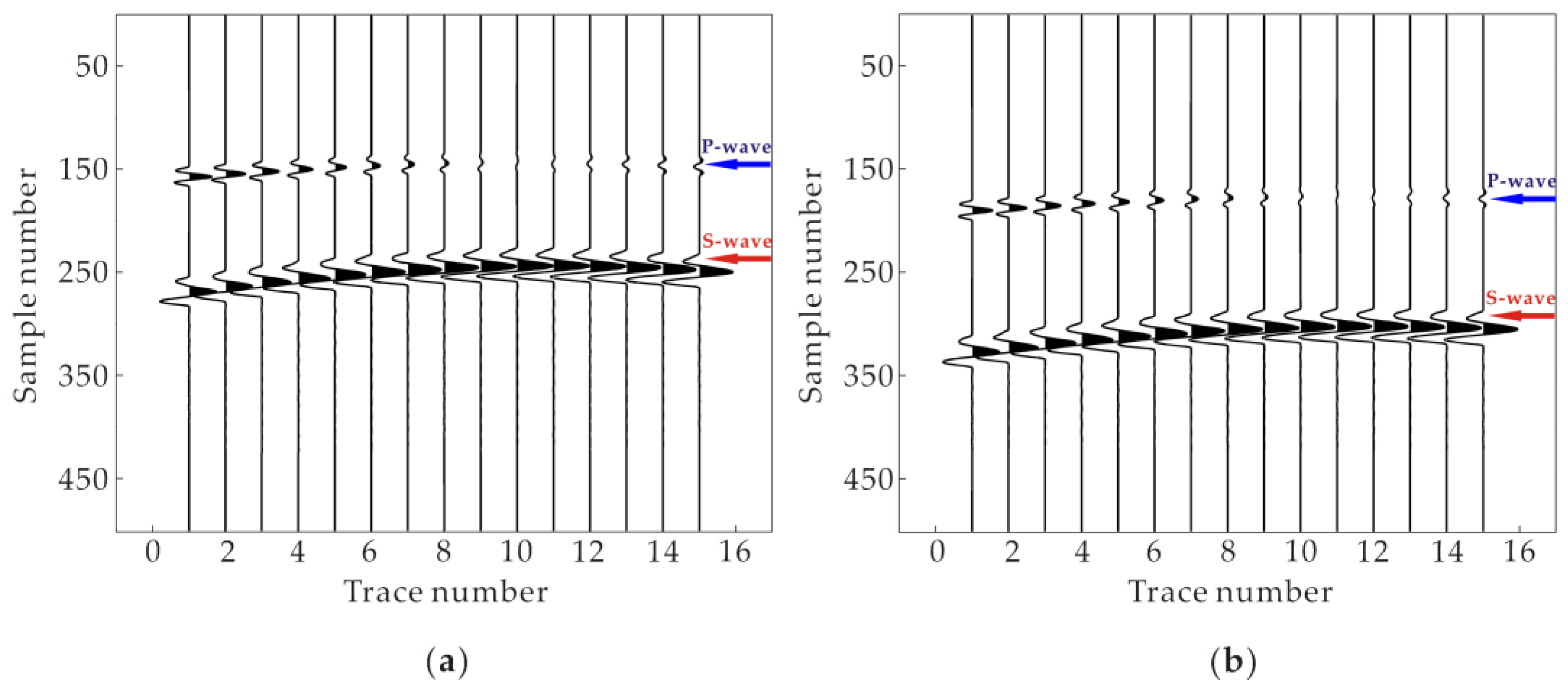
In this section, synthetic data were used to test the accuracy of the conventional and improved polarity correction methods. In order to compare and analyze the precision of the above-mentioned methods, a simple two-dimensional (2D) homogeneous model with values of density and P- and S-wave velocities of 2.1 g/cm3, 3000 m/s and 1700 m/s, respectively, was applied (Figure 2). Overall, 15 receivers were arranged at depths from 1450 to 1590 m with an interval of 10 m in a vertical observation well. The wellhead was located at x = 250 m. A Ricker wavelet was used as the source with a dominant frequency of 150 Hz. The temporal sampling rate was set as 0.5 ms. The reference and target events were located at (x, z) = (500, 1555) m and (x, z) = (450, 1545) m, respectively. 2D synthetic waveforms were generated by using the staggered-grid finite differences method and its extended approach, as proposed by Graves and Zhong et al. [42,43]. Figure 3a,b shows the vertical component (Z-component) records of the noise-free synthetic data for the target and reference events, respectively.
Subsequently, based on the synthetic microseismic data (Figure 3), P- and S-wave polarity correction coefficients for all traces were calculated using both the conventional and improved polarity correction methods as mentioned in Section 2.1.1 and Section 2.1.2. Then, we obtained the same polarity correction coefficients from two methods, which is completely correct in the absence of noise.
The noise resistance ability of the conventional and improved polarity correction methods and their corresponding location results were analyzed by varying noise levels. First of all, we performed the Monte Carlo tests with 200 realizations of independent random noise for different SNRs and calculated the SNR based on the P-wave amplitude according to Appendix A. Then, we have used a set of 200 synthetic records with the same target event under different noise realizations for different SNRs of 0.15, 0.25 and 0.5, respectively. It can be observed from Figure 4 that with the increase of SNR, there is an obvious increase in the correct counts of predicted polarity based on the conventional polarity correction method for P wave and a slight increase in the correct counts of predicted polarity based on the improved polarity correction method for P wave. However, the latter still has many more correct counts of predicted polarity than the former under any SNRs. For S-wave, the predicted polarity results based on the improved polarity correction method were completely correct under SNR = 0.15, 0.25 and 0.5 (Figure 4a–c), respectively. The above same results for the S-wave are obtained by the conventional polarity correction under SNR = 0.25 and 0.5 (Figure 4b,c), respectively. However, some small errors are present in the predicted S-wave polarity results based on the conventional polarity correction method under SNR = 0.15 (Figure 4a). In general, the precision of the improved polarity correction method is considerably higher compared to that of the conventional one in low SNR circumstances.
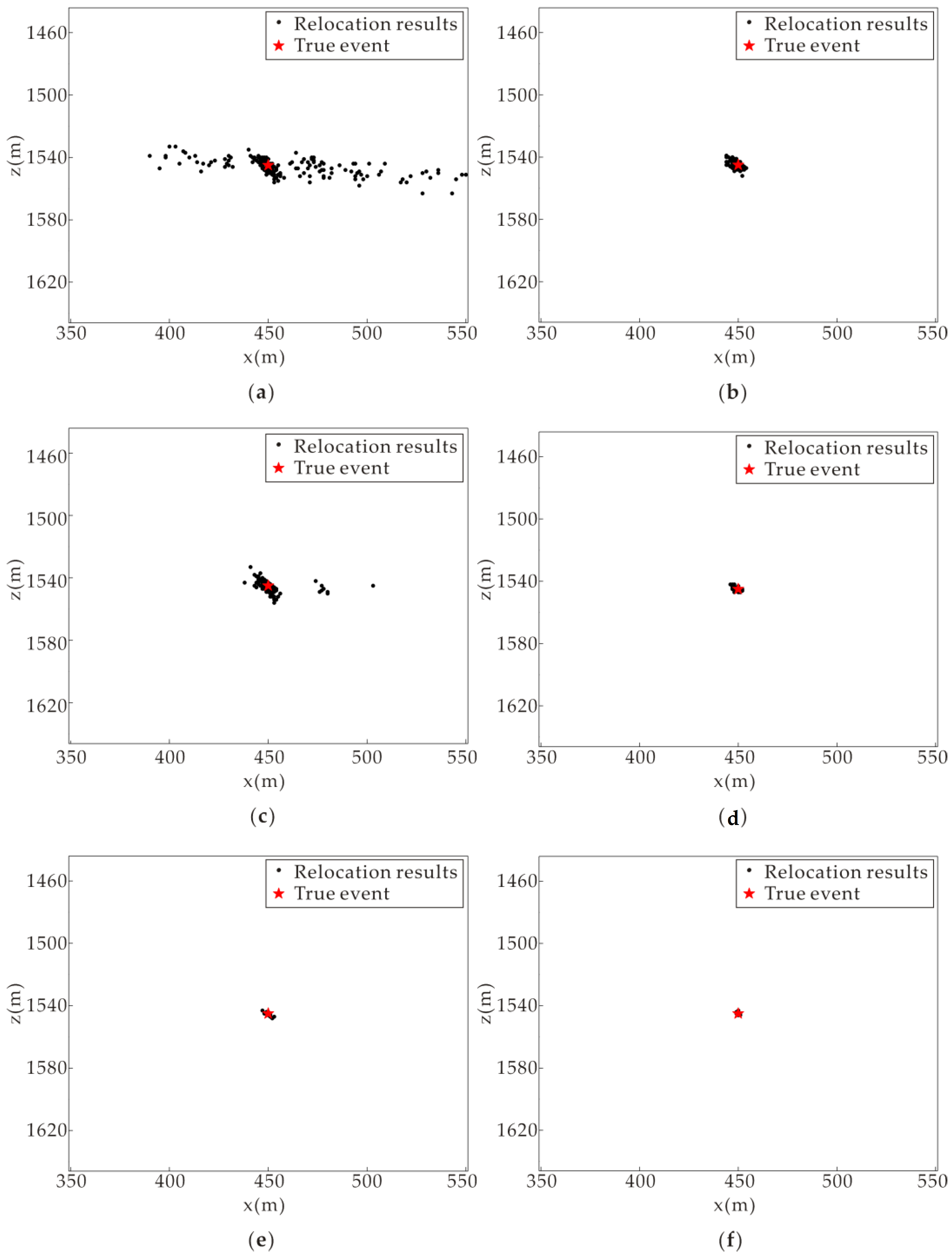
Figure 5 shows the relocation results calculated via the conventional and improved polarity correction methods, keeping the same previous parameters as in Figure 4. The obtained results (Figure 5) clearly depict that the accuracy of relocated events improves with the increase of SNR. The results of both methods show a gradual convergence to the true event location. Moreover, the results of the improved polarity correction method are far more convergent to the true event location compared to those of the conventional one under the same SNRs (0.15, 0.25 and 0.5), as shown in Figure 5a–c. Furthermore, Figure 6 depicts the comparative study of absolute location errors by adopting the same previous parameters as in Figure 5. Evidently, the absolute location errors computed based on the improved polarity correction method are far smaller compared with those calculated based on the conventional one from Figure 6. Results also illustrate that the improved polarity correction method has the ability to accurately locate the events even in the presence of low SNR data, whereas the accuracy of the conventional polarity correction method is heavily dependent upon high SNR data, as shown in Figure 6a–c. Hence, the absolute location errors of both methods also confirm the supremacy of the improved polarity correction method (Figure 6).

3.2. Field Data Example

To demonstrate the viability of the improved polarity correction method on real microseismic data, the proposed method was tested on actual microseismic data acquired from hydraulic fracturing well targeting the tight sandstone reservoir located in a Chinese oil field. The downhole acquisition geometry is represented in Figure 7. It shows an array of seven three-component (3C) geophones covering the depth from 2532.95 to 2590.18 m, installed in the single inclined monitoring well and two adjacent perforation shots in the fracturing well. The seismograms were recorded continuously for about one and a half hours, with a temporal sampling rate of 0.25 ms during hydraulic fracturing. The required calibrated velocity model was obtained using the logging and perforation data.
As discussed earlier in Section 2.1.1 and Section 2.1.2, we applied both the conventional and improved polarity correction methods at 306 microseismic events identified by using automatic event detection approach [44], respectively. Then, their polarities were corrected through both the conventional and improved polarity correction methods, respectively. The midpoint location of two adjacent perforation shots was (601.0, 440.0 and 2580.2) m, which was regarded as the midpoint of the three-dimensional (3D) grid search model with elements of size 200 m (x-direction) by 200 m (y-direction) by 200 m (z-direction). The search step size was chosen as 1 m in the x-, y- and z-directions.
Figure 8 shows the waveform stacking function distribution by applying the conventional and improved polarity correction methods for one of detected microseismic events, respectively. It can be clearly seen that the improved polarity correction method (Figure 8b,d,f) delivers more focused stacking energy at the estimated location compared to the conventional one (Figure 8a,c,e). The conventional and improved polarity correction methods may produce the destructive and constructive interference of the stacked waves at the estimated location, respectively.
The location of 306 microseismic events was calculated by adopting the workflow as discussed in Section 2.2. Figure 9a–h shows 3D space views, map views in xy-plane and views in yz- and xz-planes of location results estimated by utilizing both the conventional and improved polarity correction methods, respectively.
The presence of two approximate parallel fractures can be clearly observed in Figure 9a,b. These fractures were determined with the help of a migration-based location approach based on the conventional and improved polarity correction methods. Overall, obtained results indicate the presence of located events near to the perforation intervals. However, the improved polarity correction method provides more reliable and convergent results (Figure 9b) compared to the conventional one (Figure 9a). To further check the accuracy of both applied methods, located events were analyzed in xy-, yz- and xz-planes. Map views of xy-plane also confirm that the improved polarity correction method provides slightly better clustering of data (Figure 9d) compared to the conventional one (Figure 9c). Side views of yz-plane clearly show that the location results calculated based on the improved polarity correction method are significantly clustered (Figure 9f) compared to those found based on the conventional one (Figure 9e). In addition, side views of the xz-plane show a substantial spatial data clustering based on the improved polarity correction method (Figure 9h), compared to the conventional one (Figure 9g). The field data test also indicates that the location results yielded through applying the improved polarity correction method are far more acceptable than those estimated based on the conventional one.

4. Discussion

The findings of this study obviously imply that the improved polarity correction method provides more accurate results with minimum polarity errors compared to the conventional one. Synthetic data analysis indicates that both the conventional and improved polarity correction methods can fully obtain correct polarity results of microseismic events in the absence of noise. The accuracy of both methods was tested at different noise levels (SNR: 0.15, 0.25 and 0.5). It was observed that the accuracy of the conventional polarity method was significantly compromised in the presence of noise, whereas the improved polarity correction method was resistant to noise (Figure 4). Thus, the improved polarity correction method can provide more robust and accurate migration-based location results compared to the conventional one, at different noise levels (Figure 5 and Figure 6). The predicted polarity results of the S-wave were more accurate compared to those of the P-wave, in the application of both the conventional and improved polarity correction methods, because the SNR of the S-wave is usually higher than that of the P-wave in microseismic events. It conforms to characteristics of microseismic events excited during the actual fracturing situation. For simplicity, the 2D model is chosen in the synthetic data test. Once adding the back azimuth constraint in the 3D synthetic data test, we can readily confirm the above conclusions.
According to the field data test, one detected microseismic event is selected as an example in order to discuss the waveform stacking function distribution with polarity correction. The waveform stacking energy at the estimated location based on the improved polarity correction method is significantly focused than that based on the conventional one. Figure 8 clearly indicates that the waveform stacking consistency of the former is far better compared to that of the latter. In other words, the precision of the improved polarity correction method is much higher compared to that of the conventional one. Afterwards, the location results determined via employing the improved polarity correction method are more clustered than those estimated through the conventional one (Figure 9a–h). Obtained location results imply that the improved polarity correction method is more reliable compared to the conventional one, which is also in agreement with the conclusion drawn through the application of the synthetic data. Furthermore, Figure 9 clearly shows the presence of two approximate parallel fractures, which might indicate that the two main fractures were generated in two adjacent perforation intervals during the hydraulic fracturing process.
Overall, the presented polarity correction method can obviously be more applicable to process low SNR microseismic data compared to the conventional one. It lays the solid basis on accurate and robust implementation of migrated-based location workflow.

5. Conclusions

In this study, an improved polarity correction method based on cross correlation analysis was developed. The new method replaces only a single high SNR waveform from one target event with all waveforms from one high SNR event, which is selected as corresponding reference waveforms. Compared with the conventional polarity correction method, the proposed method produces least polarity error and subsequently obtains more precise and reliable location results even under low SNR. Therefore, the improved polarity correction method is entirely stable and feasible for migration-based location of low SNR microseismic events. The accuracy of the proposed method has been successfully verified by implementing it on synthetic and field data.
This novel method is more applicable to estimate the waveform polarities of one target event based on the corresponding waveforms from one selected reference event if both events are generated by the same source mechanism. So, the accuracy of the proposed method may be compromised to some extent if target and reference events have different source mechanisms. In future work, we intend to study further how to enhance the stability of this proposed method under the different focal mechanisms.

Author Contributions

Conceptualization, Q.M.; methodology, Q.M.; software, Q.M.; validation, Q.M. and T.A.; formal analysis, Q.M. and Y.Z.; investigation, Q.M. and P.W.; data curation, Q.M.; writing—original draft preparation, Q.M. and T.A.; writing—review and editing, Q.M. and T.A.; supervision, Z.G.; funding acquisition, Z.G. and Q.M. All authors have read and agreed to the published version of the manuscript.

Funding

This study was co-sponsored by the state key program of National Natural Science Foundation of China (grant number 42030805) and the Open Fund of Key Laboratory of Exploration Technologies for Oil and Gas Resources (Yangtze University), Ministry of Education (grant number K2021-19).

Institutional Review Board Statement

Not applicable.

Informed Consent Statement

Not applicable.

Data Availability Statement

The data presented in this study are available on reasonable request from the corresponding author.

Conflicts of Interest

The authors declare no conflict of interest.

Appendix A. Definition of SNR

In this section, we define the SNR as followed:
SNR = 1 n i = 1 n R M S i S R M S i N
where n represents the number of receivers. R M S i S and R M S i N are root mean square amplitude of signal and noise at the ith receiver, respectively.

References

  1. Li, L.; Tan, J.Q.; Wood, D.A.; Zhao, Z.G.; Becker, D.; Lyu, Q.; Shu, B.; Chen, H.C. A review of the current status of induced seismicity monitoring for hydraulic fracturing in unconventional tight oil and gas reservoirs. Fuel 2019, 242, 195–210. [Google Scholar] [CrossRef]
  2. Eisner, L.; Duncan, P.M.; Heigl, W.M.; Keller, W.R. Uncertainties in passive seismic monitoring. Lead. Edge 2009, 28, 648–655. [Google Scholar] [CrossRef]
  3. Kochnev, V.A.; Polyakov, V.S.; Goz, I.V.; Murtayev, I.S.; Savin, V.G.; Zommer, B.K.; Bryksin, I.V. Imaging hydraulic fracture zones from surface passive microseismic data. First Break 2007, 25, 77–80. [Google Scholar] [CrossRef]
  4. Beckel, R.A.; Lund, B.; Eggertsson, G.A.; Juhlin, C. Comparing the performance of stacking-based methods for microearthquake location: A case study from the Burträsk fault, northern Sweden. Geophys. J. Int. 2022, 228, 1918–1934. [Google Scholar] [CrossRef]
  5. Trojanowski, J.; Eisner, L. Comparison of migration-based location and detection methods for microseismic events. Geophys. Prospect. 2017, 65, 47–63. [Google Scholar] [CrossRef]
  6. Li, L.; Tan, J.Q.; Schwarz, B.; Staněk, F.; Poiata, N.; Shi, P.D.; Diekmann, L.; Eisner, L.; Gajewski, D. Recent advances and challenges of waveform-based seismic location methods at multiple scales. Rev. Geophys. 2020, 58, e2019RG000667. [Google Scholar] [CrossRef]
  7. Li, L.; Xie, Y.J.; Tan, J.Q. Application of waveform stacking methods for seismic location at multiple scales. Energies 2020, 13, 4729. [Google Scholar] [CrossRef]
  8. Kao, H.; Shan, S.J. The Source-Scanning Algorithm: Mapping the distribution of seismic sources in time and space. Geophys. J. Int. 2004, 157, 589–594. [Google Scholar] [CrossRef]
  9. Liao, Y.C.; Kao, H.; Rosenberger, A.; Hsu, S.K.; Huang, B.S. Delineating complex spatiotemporal distribution of earthquake aftershocks: An improved Source-Scanning Algorithm. Geophys. J. Int. 2012, 189, 1753–1770. [Google Scholar] [CrossRef] [Green Version]
  10. Zhang, W.; Zhang, J. Microseismic migration by semblance-weighted stacking and interferometry. In Proceedings of the 2013 SEG Annual Meeting, Houston, TX, USA, 22–27 September 2013; Society of Exploration Geophysicists: Houston, TX, USA, 2013; Volume 32, pp. 2045–2049. [Google Scholar]
  11. Zhang, C.W.; Qiao, W.X.; Che, X.H.; Lu, J.Q.; Men, B.Y. Automated microseismic event location by amplitude stacking and semblance. Geophysics 2019, 84, KS191–KS210. [Google Scholar] [CrossRef]
  12. Namjesnik, D.; Kinscher, J.; Gunzburger, Y.; Poiata, N.; Dominique, P.; Bernard, P.; Contrucci, I. Automatic detection and location of microseismic events from sparse network and its application to post-mining monitoring. Pure Appl. Geophys. 2021, 178, 2969–2997. [Google Scholar] [CrossRef]
  13. Gal, M.; Lotter, E.; Olivier, G.; Green, M.; Meyer, S.; Dales, P.; Reading, A.M. CCLoc—An improved interferometric seismic event location algorithm applied to induced seismicity. Seismol. Res. Lett. 2021, 92, 3492–3503. [Google Scholar] [CrossRef]
  14. Shi, P.D.; Angus, D.; Rost, S.; Nowacki, A.; Yuan, S.Y. Automated seismic waveform location using multichannel coherency migration (MCM)–I: Theory. Geophys. J. Int. 2019, 216, 1842–1866. [Google Scholar] [CrossRef]
  15. Gajewski, D.; Anikiev, D.; Kashtan, B.; Tessmer, E.; Vanelle, C. Localization of Seismic Events by Diffraction Stacking. In Proceedings of the 2007 SEG Annual Meeting, San Antonio, TX, USA, 23–28 September 2007; Society of Exploration Geophysicists: Houston, TX, USA, 2007; Volume 26, pp. 1287–1291. [Google Scholar]
  16. Rentsch, S.; Buske, S.; Lüth, S.; Shapiro, S.A. Fast location of seismicity: A migration-type approach with application to hydraulic-fracturing data. Geophysics 2007, 72, S33–S40. [Google Scholar] [CrossRef]
  17. Chen, C.; Holland, A.A. PhasePApy: A robust pure Python package for automatic identification of seismic phases. Seismol. Res. Lett. 2016, 87, 1384–1396. [Google Scholar] [CrossRef]
  18. Long, Y.; Lin, J.; Li, B.; Wang, H.C.; Chen, Z.B. Fast-AIC method for automatic first arrivals picking of microseismic event with multitrace energy stacking envelope summation. IEEE Geosci. Remote Sens. Lett. 2020, 17, 1832–1836. [Google Scholar] [CrossRef]
  19. Zhu, X.H.; Chen, B.R.; Wang, X.; Li, T. Time series segmentation clustering: A new method for S-phase picking in microseismic data. IEEE Geosci. Remote Sens. Lett. 2022, 19, 1–5. [Google Scholar] [CrossRef]
  20. Grigoli, F.; Cesca, S.; Vassallo, M.; Dahm, T. Automated seismic event location by travel-time stacking: An application to mining induced seismicity. Seismol. Res. Lett. 2013, 84, 666–677. [Google Scholar] [CrossRef]
  21. Grigoli, F.; Cesca, S.; Amoroso, O.; Emolo, A.; Zollo, A.; Dahm, T. Automated seismic event location by waveform coherence analysis. Geophys. J. Int. 2014, 196, 1742–1753. [Google Scholar] [CrossRef] [Green Version]
  22. Grigoli, F.; Cesca, S.; Krieger, L.; Kriegerowski, M.; Gammaldi, S.; Horalek, J.; Priolo, E.; Dahm, T. Automated microseismic event location using master-event waveform stacking. Sci. Rep.-UK. 2016, 6, 25744. [Google Scholar] [CrossRef] [Green Version]
  23. Li, L.; Becker, D.; Chen, H.; Wang, X.M.; Gajewski, D. A systematic analysis of correlation-based seismic location methods. Geophys. J. Int. 2018, 212, 659–678. [Google Scholar] [CrossRef]
  24. Li, L.; Tan, J.Q.; Xie, Y.J.; Tan, Y.Y.; Walda, J.; Zhao, Z.G.; Gajewski, D. Waveform-based microseismic location using stochastic optimization algorithms: A parameter tuning workflow. Comput. Geosci.-UK. 2019, 124, 115–127. [Google Scholar] [CrossRef]
  25. Jiang, Y.J.; Peng, P.A.; Wang, L.G.; He, Z.X. Automated locating mining-induced microseismicity without arrival picking by weighted STA/LTA traces stacking. Sustainability 2020, 12, 3665. [Google Scholar] [CrossRef]
  26. Baker, T.; Granat, R.; Clayton, R.W. Real-time earthquake location using Kirchhoff reconstruction. Bull. Seismol. Soc. Am. 2005, 95, 699–707. [Google Scholar] [CrossRef] [Green Version]
  27. Gharti, H.N.; Oye, V.; Roth, M.; Kühn, D. Automated microearthquake location using envelope stacking and robust global optimization. Geophysics 2010, 75, MA27–MA46. [Google Scholar] [CrossRef]
  28. Li, L.; Chen, H.; Wang, X.M. Relative elastic interferometric imaging for microseismic source location. J. Geophys. Eng. 2016, 13, 733–744. [Google Scholar] [CrossRef]
  29. Zhang, X.; Zhang, W.; Zhang, J. Detecting and locating microseismic events with stacking velocity analysis for surface monitoring. J. Appl. Geophys. 2021, 195, 104470. [Google Scholar] [CrossRef]
  30. Anikiev, D.; Stanek, F.; Valenta, J.; Eisner, L. Imaging microseismic events by diffraction stacking with moment tensor inversion. In Proceedings of the 2013 SEG Annual Meeting, Houston, TX, USA, 22–27 September 2013; Society of Exploration Geophysicists: Houston, TX, USA, 2013; Volume 32, pp. 2013–2018. [Google Scholar]
  31. Anikiev, D.; Valenta, J.; Staněk, F.; Eisner, L. Joint location and source mechanism inversion of microseismic events: Benchmarking on seismicity induced by hydraulic fracturing. Geophys. J. Int. 2014, 198, 249–258. [Google Scholar] [CrossRef] [Green Version]
  32. Zhebel, O.; Eisner, L. Simultaneous microseismic event localization and source mechanism determination. Geophysics 2015, 80, KS1–KS9. [Google Scholar] [CrossRef]
  33. Liang, C.T.; Yu, Y.Y.; Yang, Y.H.; Kang, L.; Yin, C.; Wu, F.R. Joint inversion of source location and focal mechanism of microseismicity. Geophysics 2016, 81, KS41–KS49. [Google Scholar] [CrossRef]
  34. Yu, Y.Y.; Liang, C.T.; Wu, F.R.; Wang, X.B.; Yu, G.; Chu, F.D. On the accuracy and efficiency of the joint source scanning algorithm for hydraulic fracturing monitoring. Geophysics 2018, 83, KS77–KS85. [Google Scholar] [CrossRef]
  35. Xu, J.C.; Zhang, W.; Liang, X.; Rong, J.J.; Li, J.L. Joint microseismic moment-tensor inversion and location using P- and S-wave diffraction stacking. Geophysics 2021, 86, KS137–KS150. [Google Scholar] [CrossRef]
  36. Tian, X.; Zhang, W.; Zhang, X.; Zhang, J.; Zhang, Q.S.; Guo, Q.S. Comparison of single-trace and multiple-trace polarity determination for surface microseismic data using deep learning. Seismol. Res. Lett. 2020, 91, 1794–1803. [Google Scholar] [CrossRef]
  37. Xu, J.C.; Zhang, W.; Chen, X.F.; Guo, Q.S. Minimum semblance weighted stacking with polarity correction for surface microseismic data processing. Lead. Edge 2019, 38, 630–636. [Google Scholar] [CrossRef]
  38. Xu, J.C.; Zhang, W.; Chen, X.F.; Guo, Q.S. An effective polarity correction method for microseismic migration-based location. Geophysics 2020, 85, KS115–KS125. [Google Scholar] [CrossRef]
  39. Kim, J.; Woo, J.U.; Rhie, J.; Kang, T.-S. Automatic determination of first-motion polarity and its application to focal mechanism analysis of microseismic events. Geosci. J. 2017, 21, 695–702. [Google Scholar] [CrossRef]
  40. Yilmaz, Ö. Seismic Data Analysis: Processing, Inversion, and Interpretation of Seismic Data, 2nd ed.; Society of Exploration Geophysicists: Tulsa, OK, USA, 2001; Volume 1, pp. 39–41. [Google Scholar]
  41. Mao, Q.H.; Azeem, T.; Zhang, X.L.; Zhong, Y.; Fang, Y.; Zhang, Y.X. A migration-based location method using improved waveform stacking for microseismic events in a borehole system. Acta Geophys. 2020, 68, 1609–1618. [Google Scholar] [CrossRef]
  42. Graves, R.W. Simulating seismic wave propagation in 3D elastic media using staggered-grid finite differences. Bull. Seismol. Soc. Am. 1996, 86, 1091–1106. [Google Scholar]
  43. Zhong, Y.; Gu, H.; Liu, Y.; Mao, Q. Elastic Reverse-Time Migration with Complex Topography. Energies 2021, 14, 7837. [Google Scholar] [CrossRef]
  44. Wang, P.; Chang, X.; Wang, Y.B.; Wang, L.C.; Zhai, H.Y. Automatic event detection and event recovery in low SNR microseismic signals based on time-frequency sparseness. Chin. J. Geophys. 2014, 57, 2656–2665. [Google Scholar]
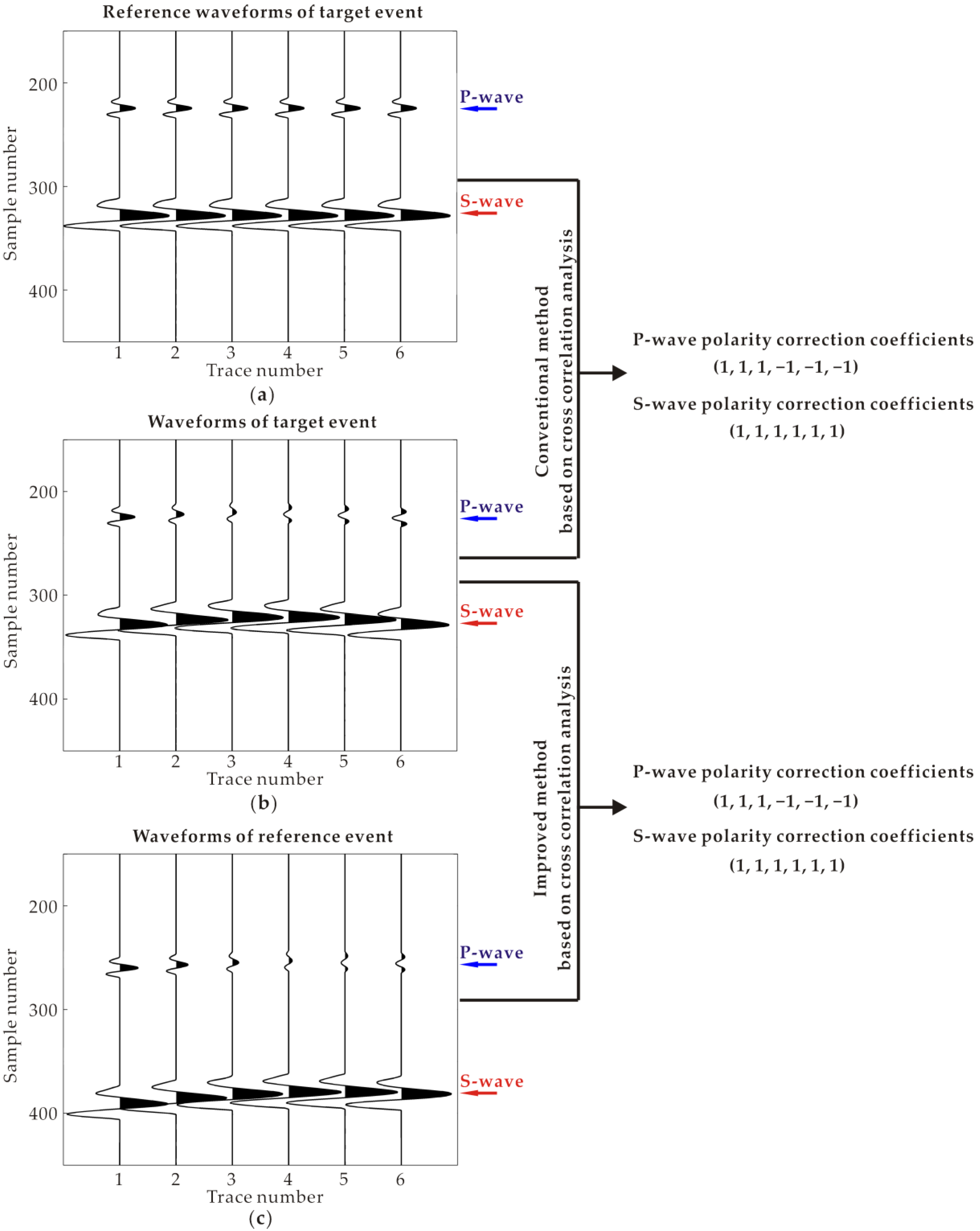
Figure 1. Illustration of polarity correction through conventional and improved methods based on cross correlation analysis. (a) Reference waveforms of target event, (b) waveforms of target event and (c) waveforms of reference event.
Energies 15 02772 g001
Figure 2. Downhole acquisition geometry of 2D homogeneous model. The x- and z-axes indicate the offset and depth directions, respectively.
Energies 15 02772 g002
Figure 3. Z-component record section of the noise-free synthetic data for the (a) target and (b) reference events.
Energies 15 02772 g003
Figure 4. Comparison with correct counts of predicted polarity from the 200 realizations in the Monte Carlo test using the conventional and improved polarity correction methods, under independent random noise for different SNRs of (a) 0.15, (b) 0.25 and (c) 0.5. Blue and green solid lines represent correct counts of predicted polarity based on the conventional polarity correction method for P- and S-waves, respectively. Red and black dashed lines indicate correct counts of predicted polarity based on the improved polarity correction method for P- and S-waves, respectively.
Energies 15 02772 g004
Figure 5. Relocation results obtained by applying the conventional (a,c,e) and improved (b,d,f) polarity correction methods through the utilization of the same corresponding 200 realizations as in Figure 4, respectively. The black dots and red pentagram denote relocation results and the true location of the target event, respectively. SNR is (a,b) 0.15, (c,d) 0.25 and (e,f) 0.5, respectively.
Energies 15 02772 g005
Figure 6. Comparison of absolute location errors with the utilization of same corresponding 200 realizations as in Figure 5 using different SNR levels of (a) 0.15, (b) 0.25 and (c) 0.5.
Energies 15 02772 g006
Figure 7. Downhole acquisition geometry of the real data set. (a) 3D display and (b) map view of acquisition geometry with the fracturing (red curve) and the monitoring (blue curve) wells, seven receivers (blue triangles) and two perforation shots (red pentagram). The x-, y- and z-axes represent the East, North and depth directions, respectively.
Energies 15 02772 g007
Figure 8. Waveform stacking function distribution for one of the identified microseismic events through applying the conventional and improved polarity correction methods. The horizontal slice of the waveform stacking function estimated in the xy-plane using (a) the conventional polarity correction method and (b) the improved polarity correction method. The vertical slice of waveform stacking function estimated in the xz-plane using (c) the conventional polarity correction method and (d) the improved polarity correction method. The vertical slice of waveform stacking function estimated in yz-plane using (e) the conventional polarity correction method and (f) the improved polarity correction method. The color scale denotes the waveform stacking function value (low values in blue and high values in red). The spot with the maximum value indicates the most likely position of the located event.
Energies 15 02772 g008
Figure 9. The location results through applying the conventional and improved polarity correction methods. 3D display, map view in xy-plane and side views in yz- and xz-planes are shown in (a,c,e,g) for the conventional polarity correction method, respectively. The corresponding planes for the improved polarity correction method are described in (b,d,f,h). The black dots denote location results.
Energies 15 02772 g009
Publisher’s Note: MDPI stays neutral with regard to jurisdictional claims in published maps and institutional affiliations.