Abstract
Wind turbine blades perform the most important function in the wind energy conversion process. It plays the most vital role of absorbing the kinetic energy of the wind, and converting it to mechanical energy before it is transformed into electrical energy by generators. In this work, National Advisory Committee for Aeronautics (NACA) 4412 and SG6043 airfoils were selected to design a small horizontal axis variable speed wind turbine blade for harvesting efficient energy from low wind speed areas. Due to the low wind profile of the targeted area, a blade of one-meter radius was considered in this study. To attain the set objectives of fast starting time and generate more torque and power at low wind speeds, optimization was carryout by varying Reynolds numbers (Re) on tip speed ratios (TSR) values of 4, 5, and 6. The blade element momentum (BEM) method was developed in MATLAB programming code to iteratively find the best twist and chord distributions along the one-meter blade length for each Re and tip speed ratio (TSR) value. To further enhance the blade performance, the twist and chord distributions were transferred to Q-blade software, where simulations of the power coefficients (Cp) were performed and further optimized by varying the angles of attack. The highest power coefficients values of 0.42, 0.43, and 0.44 were recorded with NACA 4412 rotor blades, and 0.43, 0.44, and 0.45 with SG6043 rotor blades. At the Re of 3.0 × 10⁵, the blades were able to harvest maximum power of 144.73 watts (W), 159.69 W, and 201.04 W with the NACA 4412 and 213.15 W, 226.44 W, 245.09 W with the SG6043 at the TSR of 4, 5, and 6 respectively. The lowest cut-in speed of 1.80 m/s and 1.70 m/s were achieved with NACA 4412 and SG6043 airfoils at TSR 4. At a low wind speed of 4 m/s, the blades were able to harness an efficient power of 79.3. W and 80.10 W with both rotor blades at the TSR 4 and 6 accordingly.
1. Introduction
World energy consumption has been rising due to the rapid development of industries and growth in the world’s population. Developing clean, efficient, and sustainable energy is no doubt the only solution to the ever-increasing energy demand and overdependency on fossil fuels [1,2]. Due to its abundant, inexhaustible, and non-polluting nature, the wind is considered one of the most promising and rapidly growing sources of energy for electricity production when compared to other renewable energy resources [3]. Many countries are aspiring to harness power from the wind in its optimum quantity. However, in some countries such as Malaysia, the wind speed is not strong enough to effectively turn the existing large wind turbine (WT) to produce useful power. This posed a great challenge regarding power generation from the wind in these zones. Unlike large WTs, small-sized WTs can harness power regardless of optimum wind speed conditions [4]. This makes small-sized wind turbines the most promising candidate for power harvesting from low wind profile areas.
Wind turbine blades (WTB) perform the most important function in the wind energy conversion process. They play the most vital role of absorbing the kinetic energy of the wind and converting it to mechanical energy before it is transformed into electrical energy by generators [5]. Optimum extraction of energy from wind depends on the aerodynamic design of the blade. Parameters associated with blade geometry optimization are important because once optimized, smaller blades would generate much more power compared to less optimized larger blades [6,7]. Blade aerodynamic optimization is achieved through proper choice of the number of blades (B), airfoil shape, tip speed ratio (TSR), and radial distribution of both chord length (c) and twist () [8]. Power extraction and starting torque are the main considering factors when designing WTBs for low wind speed applications [5]. When operating at low wind speed regions, small-sized WTs are prone to the formation of laminar separation bubbles on their blades. This causes an excessive increase in drag force and a decrease in the aerodynamic lift, resulting in the reduction of the turbine’s overall performance [6,9]. The performance of small WTs can be enhanced by lowering the cut-in speed, increasing the output power at low wind speeds, and reducing the rated speed [10]. These can be achieved via different tasks, such as selecting the best airfoils and Reynolds number (Re), choosing the right tip speed ratio (TSR), and suitable blade size for the expected power output. The underperformance issue arising from low Re emanating from small-sized rotor blades and low wind speeds can be improved by selecting low Re airfoils that are specially designed for low wind speeds application [4,11]. Airfoil selection is the first step and the most fundamental task. The overall performance of the turbine considerably improved when specially designed low Re airfoils were used [11]. For optimum performance of small WTs in low wind speeds, airfoils of low Re must be designed to avoid high suction peaks at the leading-edge and high-pressure gradients that will result to flow separation [6]. To decrease the suction peak near the leading edge, thin airfoils are chosen for low Re applications [6,12].
To maximize the power coefficient and the torque generated, the coefficient of the drag along with the lift must be minimized, while the coefficient of the lift, and the lift-to-drag ratio, for the airfoil must be maximized [1,6]. Furthermore, the performance of the rotor blade can be improved by increasing the size and the number of WTBs, thereby improving the starting time, the power coefficient, and the overall energy of the whole system [13,14]. However, this attracts an increase in the cost of the system. Moreover, small-sized WTs operating under low wind speeds have low blade rotational speed. From the power–torque relation, the power harvesting of WT is a function of the torque and the rotational speed, which means, at low wind speed, only an increase in the torque will raise the output power. Furthermore, the torque and the TSR are inversely related. Therefore, the torque can be increased by lowering the blade TSR. Based on the above relations, one can conclude that under low wind speeds, the overall performance of small-sized WTs can be improved by lowering the design TSR.
Although there exists a large variety of methods for predicting the performance and loadings of wind turbines, due to its strong agreement with experimental data, the blade element momentum theory (BEMT), which was put forward by Glauert [15], is the most popular theory used extensively by wind turbine researchers and manufacturers for WTB design and optimization [4]. By employing the BEMT, the aerodynamic performance of the WT is predicted using the airfoil characteristics data [10]. The theory combined the results of the two approaches: the momentum theory, and the blade element theory, to solve the axial and tangential induction factors. The turbine thrust and torque and other performance parameters are then calculated using the obtained axial and tangential induction factors [16,17]. The advantage of the model is that it is easy to implement and can be used on a computer. In addition, it requires less computational time, as compared with the other methods, such as Computational Fluid Dynamics (CFD). The model divides the blade into several independent elements (sections) along the length. It further assumes that the aerodynamic forces on each element can be calculated as a two-dimensional airfoil subjected to the flow conditions.
Several research works have been reported on small wind turbines design [6,7,8,11,18,19,20] and performance optimization [13,21,22,23,24,25,26,27]. For instance, the design and performance optimization of a small-sized horizontal axis WT was performed by Chaudhary et al. [8]. In the study, airfoil SG6043 was considered, and the optimization was achieved through the twist and chord distributions on the blade. A maximum power coefficient value of 0.4 was achieved with the three blades at TSR 6 corresponding to a pitch angle of 0°. A maximum power of 422 watts (W) was obtained with the five blades rotor, and the lowest cut-in speed of 2.3 m per second (m/s) was recorded with seven blades WT. Moreover, El-Okda et al. [20] applied BEM theory on SG6043 airfoil to design a small horizontal axis wind turbine with three blades and five blades. On optimizing the blade twist and chord distribution along the 2-m blade length, a maximum power coefficient value of 0.53 was found at a design wind speed of 6 m/s and TSR of 6. In a similar study, El-Okda et al. [20] applied blade element momentum theory (BEMT) in conjunction with Schmitz to design three blade and five blade optimum rotor of 2-m radius using SG6043. A maximum power coefficient of 0.52 was obtained at a designed wind speed of 6 m/s and TSR 6 for the three blade rotor, while a 0.54 power coefficient was found with five blades at the TSR 7. Wen et al. [26] presented a small wind turbine blade designed as a partial solution to the low wind speed region of Malaysia. NACA 4412 airfoil was considered, and the optimization was carried out by studying the best TSR that would yield the highest power coefficient for each Res. They recorded the highest power coefficient values at the TSR of 8, 6, and 5 for the Re values of 3.5 × 10⁵, 2.5 × 10⁵, and 2.0 × 10⁵ respectively. Furthermore, they also obtained the power output values of approximately 20 W at the designed wind speed of 4 m/s and rated power of 64.5 watts (W), and 66 W at the rated wind speed of 7 m/s for the Re 2.5 × 10⁵ and 3.0 × 10⁵, respectively. The turbine cut-in speed was recorded as 2.0 m/s. To meet the needs of the end of a rural house for low wind speed region, Kale et al. [7] also applied the BEMT to study the functional and aerodynamic design of a 0.8-m length blade using NACA 4412 profile. The optimization was carried out with the objectives of enhancement of power performance and low-speed starting behavior. The blade chord and thickness were reduced through multiple iterations, which led to a 30% increase in power coefficient. The optimized blade was able to harvest 600 W wind power. In order to meet the power requirements of Addis Abba city, Ref. [28] designed a one-meter radius wind turbine of 0.43 power coefficient at TSR 4.7 that can generate power of 25 kilowatt-hours (kWh) in an average wind speed of 8 m/s. Similarly, Muhsen et al. [4] applied the BEMT method to design and optimize a two-meters radius blade with S1210 and S1223 airfoils. The optimization process was carried out by extracting the best section of the selected airfoils that will yield optimal blade performance. Under a low wind speed of 5.5 m/s, they recoded the power coefficient value of 0.445 at a TSR of 6.5 with the cut-in speed of 4 m/s and output power of 650 W. In another perspective, Yavuz et al. [25] conducted a numerical study on NACA 4412 blade with a slat-airfoil arrangement, and found the optimum flow conditions for the wind speed of 1 m/s. The power coefficient was improved to 0.506, and reasonable agreement was reported with experimental values. Experimental and theoretical investigation of small-sized WT blade was performed by Akour et al. [14], and the optimization process was achieved using Re as the objective funtion to obtain the optimal blade geometry. A power coeficient values of 0.38 was recorded theoritecal and 0.34 experimental the TSR of 4.4 and 3.5 rspectively. Power output value of 25 W was obtained at the design wind speed of 5 m/s.
From the above literature, it is clear that the performance of WTs under specified wind condition is directly dependent on the blade’s number, size and geometry, the TSR, and Re. The optimization processes were carried out using the parameters for blade designs mentioned above in different combinations. To the best of our knowledge, no optimization process was conducted by varying low Res on TSR values. To harness as much power as possible in low wind speed areas, there is still a need to further enhance the design and optimization process. Furthermore, it is clear from the works of Wen et al. [26], Akour et al. [14] that the blade recorded a good power coefficient, but the output power at the design wind speed and rated speed are insufficiently low. However, in the work of Muhsen et al. [4], the power coefficient and the power output generated are good. However, a longer size of the blade will attract more costs that are undesirable. In addition, the TSR values are large which hike the cut-in speed.
In the present work, NACA 4412 and SG6043 airfoils were selected to design a small horizontal axis WT blade for application in low wind speeds areas. With the objective to achieve fast start-up, high power coefficient, and power output under low wind speed conditions, a wind speed of 4 m/s was chosen as the design wind speed while TSR of 4, 5, and 6 values are selected for the design.
2. Methods
To achieve the set objective, a low Re of , and were selected and developed. MATLAB codes based on Equations (1b)–(7) were used to calculate the best twist and chord distributions along the blade radius as the first step of the optimization process. For each of the Re, the MATLAB (private computer equipped with Core(TM) Intel(R) 8 G RAM 2.9 GHz CPU and i7)codes iteratively compute the optimal values of the chord and twist distributions. Q-blade (private computer equipped with Core(TM) Intel(R) 8 G RAM 2.9 GHz CPU and i7) software was used for airfoils characteristics data importation and extrapolations, XFOIL (private computer equipped with Core(TM) Intel(R) 8 G RAM 2.9 GHz CPU and i7) design, rotor blade design, rotor BEMT, and multi-parameter BEMT power simulations. The design parameters which are the inputs to the MATLAB program include the rotor radius, TSR, Re, the airfoil lift, and drag coefficients ( ), and the angles of attack. The optimum values of the chord and twist distribution obtained from the MATLAB program codes were then transferred to the Q-blade software and further optimization was carried out by varying the low Re for each TSR value of 4, 5, and 6. Finally, simulations of rotor bade design power coefficients and rotor power output for wind speeds range of 0–8 m/s were performed respectively.
2.1. Blade Design Equations
The rotational speed, Ω of a rotor blade for the design wind speed, TSR and rotor blade length is calculated using Equation (1a):
where , , and are the TSR, wind speed, and rotor blade length. The local TSR, for each blade’s element is defined as a function of design TSR, blade length, and the local radius, r is by Equation (1b):
Moreover, the mathematical expression for Re of airflow over an airfoil is given by Equation (2):
where, , and are the relative wind speed, the chord length, the air density, and air viscosity, respectively.
The initial angle of the relative wind, is calculated using Equation (3):
Using the value of obtained from Equation (3), the axial and tangential induction factors are computed from Equation (4):
where , and are the solidity, axial, and tangential induction factors of the blades, respectively.
Through multiple iterations, the best values for the two induction factors (convergence point) are obtained and these values were then used in Equation (5) to find the optimum relative wind angle, .
Hence, the optimum twist angle, , and the chord length, c, distributions along the rotor blade span were achieved using Equations (6) and (7), respectively:
where , are the twist angle, local TSR, the angle of attack, and the pitch angle respectively at each section of the blade.
Rotor blade efficiency is obtained using Equation (8):
where F is the tip loss factor.
The power output for each element is determined using Equation (9).
The total power of the blade is calculated using Equation (10), where B is the number of blades:
where is the relative wind velocity, and remain the lift and drag coefficients of the airfoils.
Furthermore, the mechanical power extracted by the WT from the wind is given by Equation (11):
where is the extractable power (W) from the wind by the wind turbine, is the turbine’s maximum efficiency, and is the available wind speed.
2.2. Design Wind Speed and Blade Diameter
The design wind speed was determined and approximated as 4 m/s based on the Malaysian annual mean wind speed (AMWS) of 2 m/s to 3.5 m/s. In addition, considering the international standard of the IEC61400-2 guide [26] which stated that the design wind speed should be 1.4 times the AMWS [28]. Furthermore, looking at the low wind speeds of the targeted area, 1-m and 0.2-m radius were selected for the blade and rotor hub to generate optimal power.
2.3. Design Tip Speed Ratio, Rotational Speed, and Local Tip Speed Ratio
One of the parameters of blade design that determine the start-up speed of the rotor blade is the TSR. Based on the torque requirement for fast starting-up and optimum power harvesting at a low wind speed regime, TSR 4, 5, and 6 were selected for the design, and then Equation (1a) was applied to determine the rotational speed Ω, for each TSR. As given in Table 1, the value of the rational speed is the point at which the rotor blade will yield its maximum power at the design wind speed and TSR.

Table 1.
Rotation Speed of different TSR.
2.4. Airfoils Selection, Reynolds Numbers, and Angle of Attack
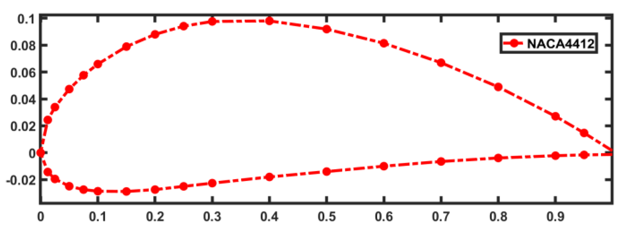
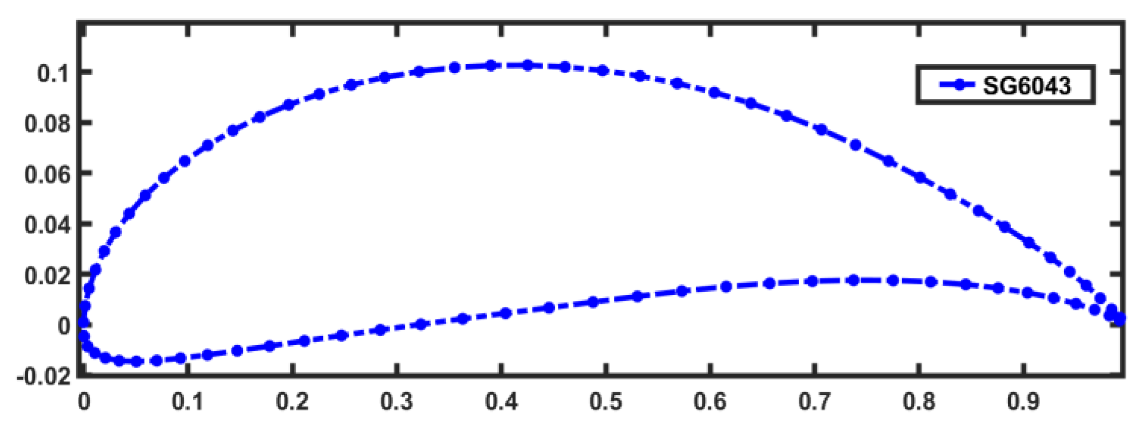
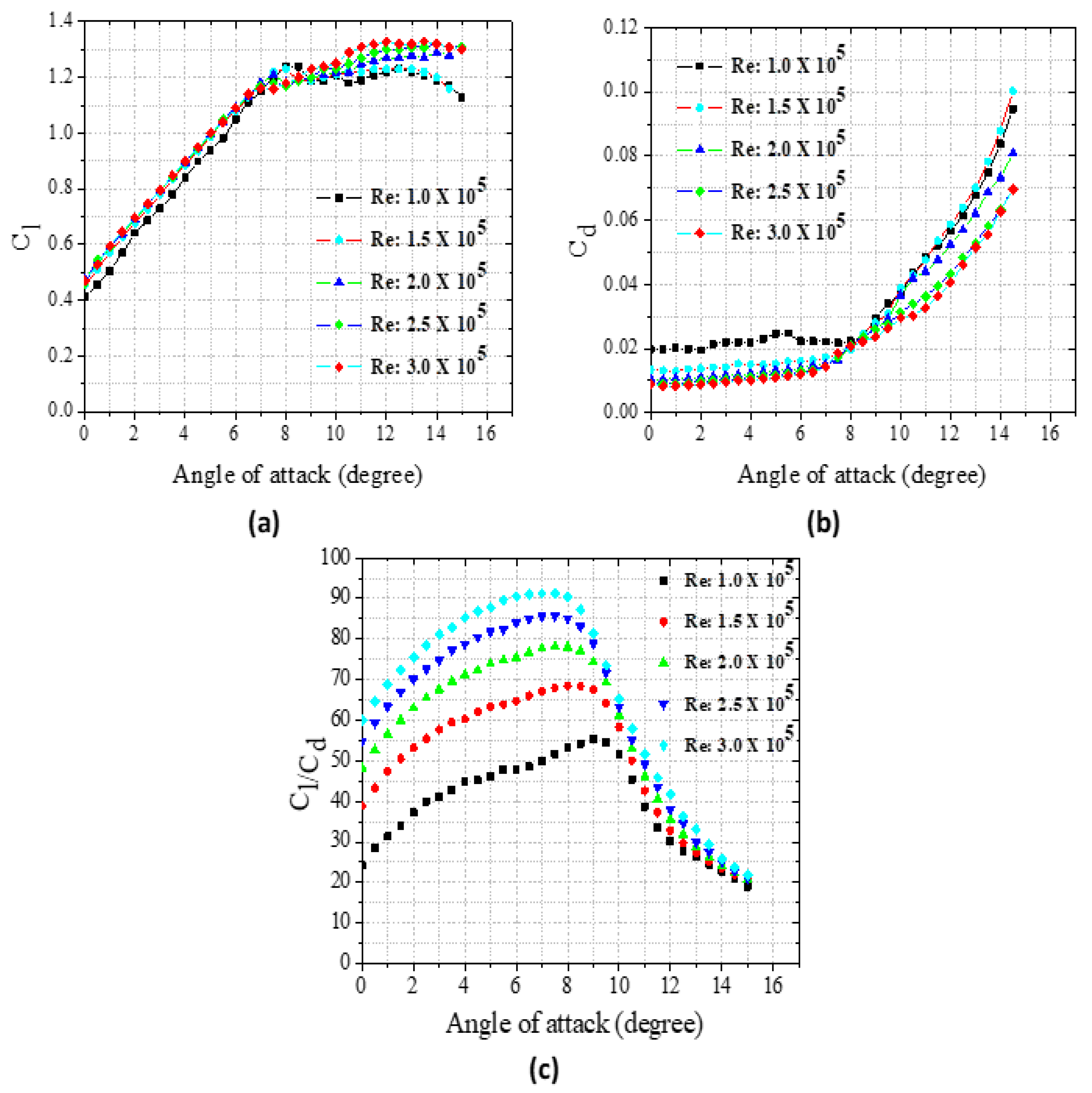
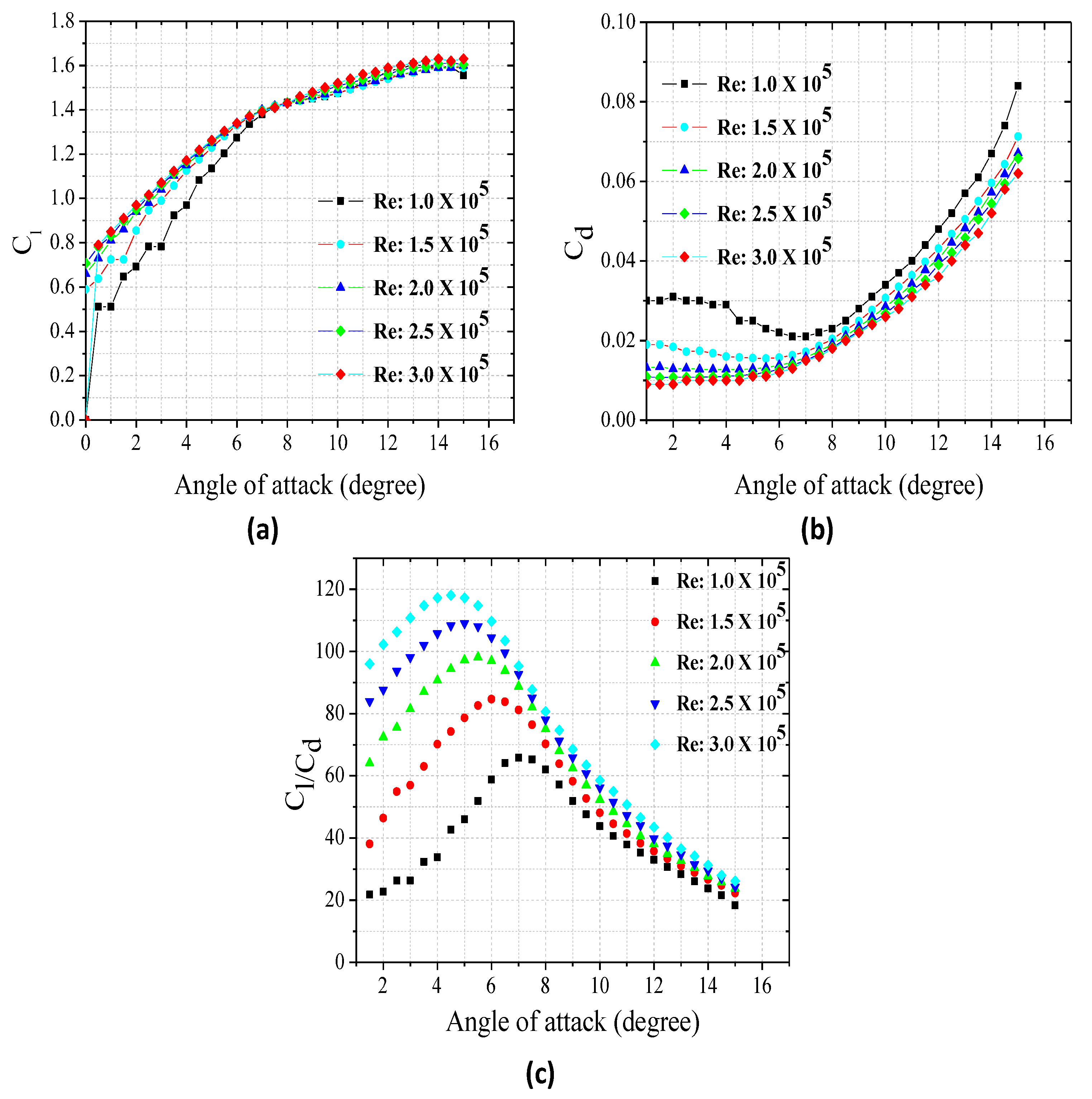
Selection for the best airfoil suitable for applications under specified conditions is the fundamental task during rotor blade design. The primary function of the airfoil is to increase lift by reducing the pressure on the upper surface so that sufficient torque is generated. Rotor blade performance can be optimized by selecting airfoils shape that will give a high lift and lift-to-drag ratio. High lift-to-drag ratio airfoils is desirable for small-size rotors, since they generate high values of torque and offer a good response for low wind speed to generate optimum power. In addition, optimum performance of a rotor blade is achieved under low wind conditions, when Re numbers defined by Equation (2) are optimized alongside other parameters considered by the BEMT. Since low Re results from the operation of small-sized rotor WTs in a low wind speeds regime, in order to obtain a high-performance rotor in this situation, the airfoil must have a high lift and lift-to-drag ratio at low Re and angle of attack. Hence, NACA 4412 and SG6043 airfoils are selected for this work (Figure 1 and Figure 2). The blade span of a one-meter radius is then divided into 10 elements of equal length. Low Re of , , and were considered and the airfoils data files are exported into the Q-blade software and analysis of their lift and drag coefficients were carryout at the different Re. The points of maximum lift and minimum drag coefficients that will yield maximum glide ratio and their optimum angles of attack were determined for each of the selected Re as shown in Figure 3 and Figure 4.

Figure 1.
NACA 4412 Airfoil shape.
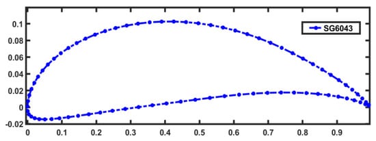
Figure 2.
SG6043 Airfoil shape.
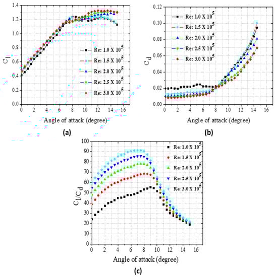
Figure 3.
NACA 4412 airfoils (a) lift coefficients; (b) drag coefficients; (c) lift-to-drag ratio at the various angle of attack.
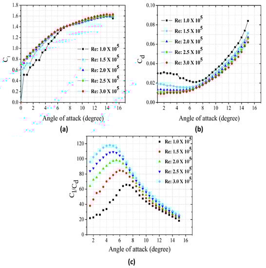
Figure 4.
SG6043 airfoils (a) lift coefficients; (b) drag coefficients; (c) lift-to-drag ratio at the various angle of attack.
2.5. Relative Wind Angle, Twist, and Chord Distributions
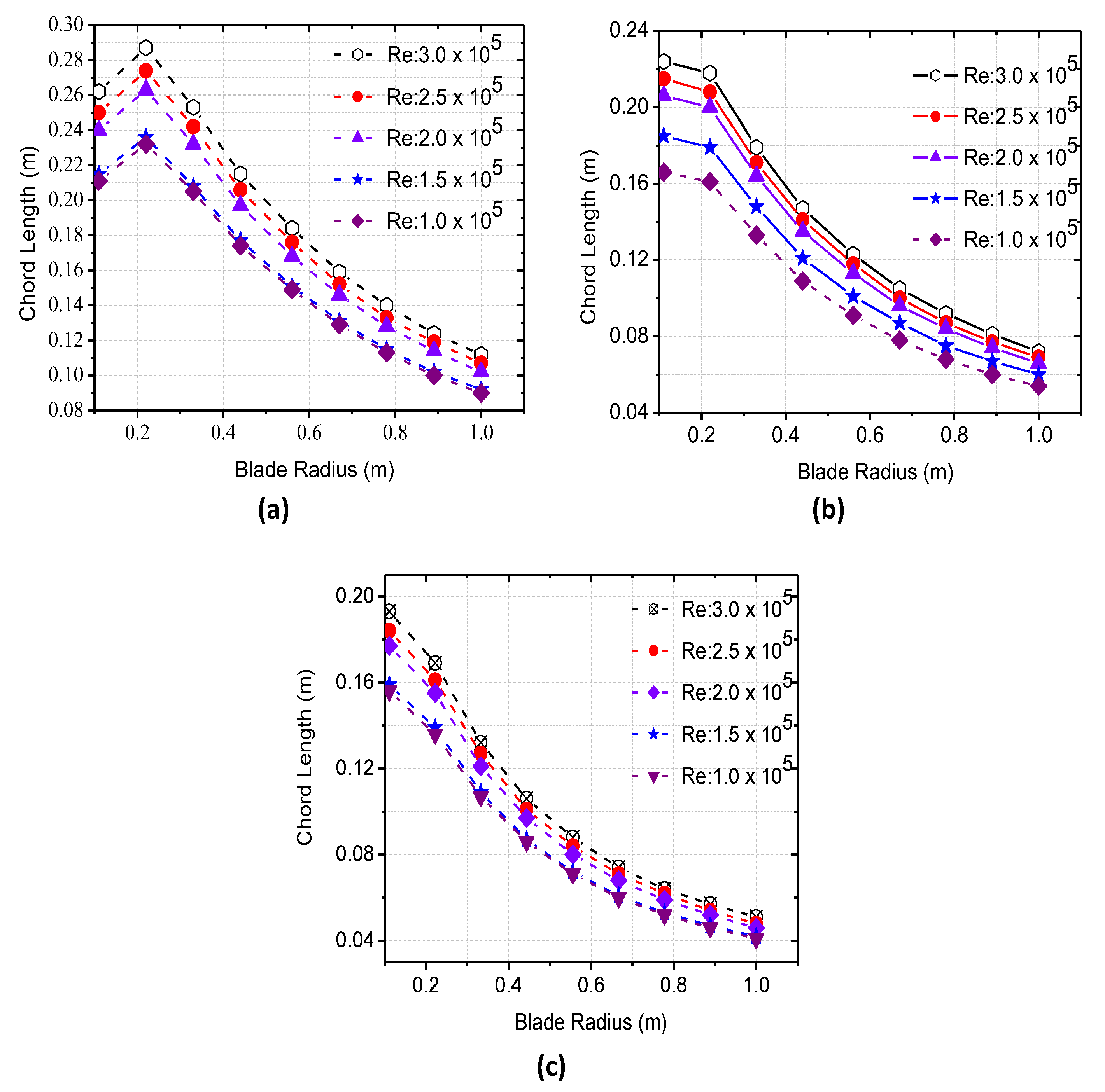
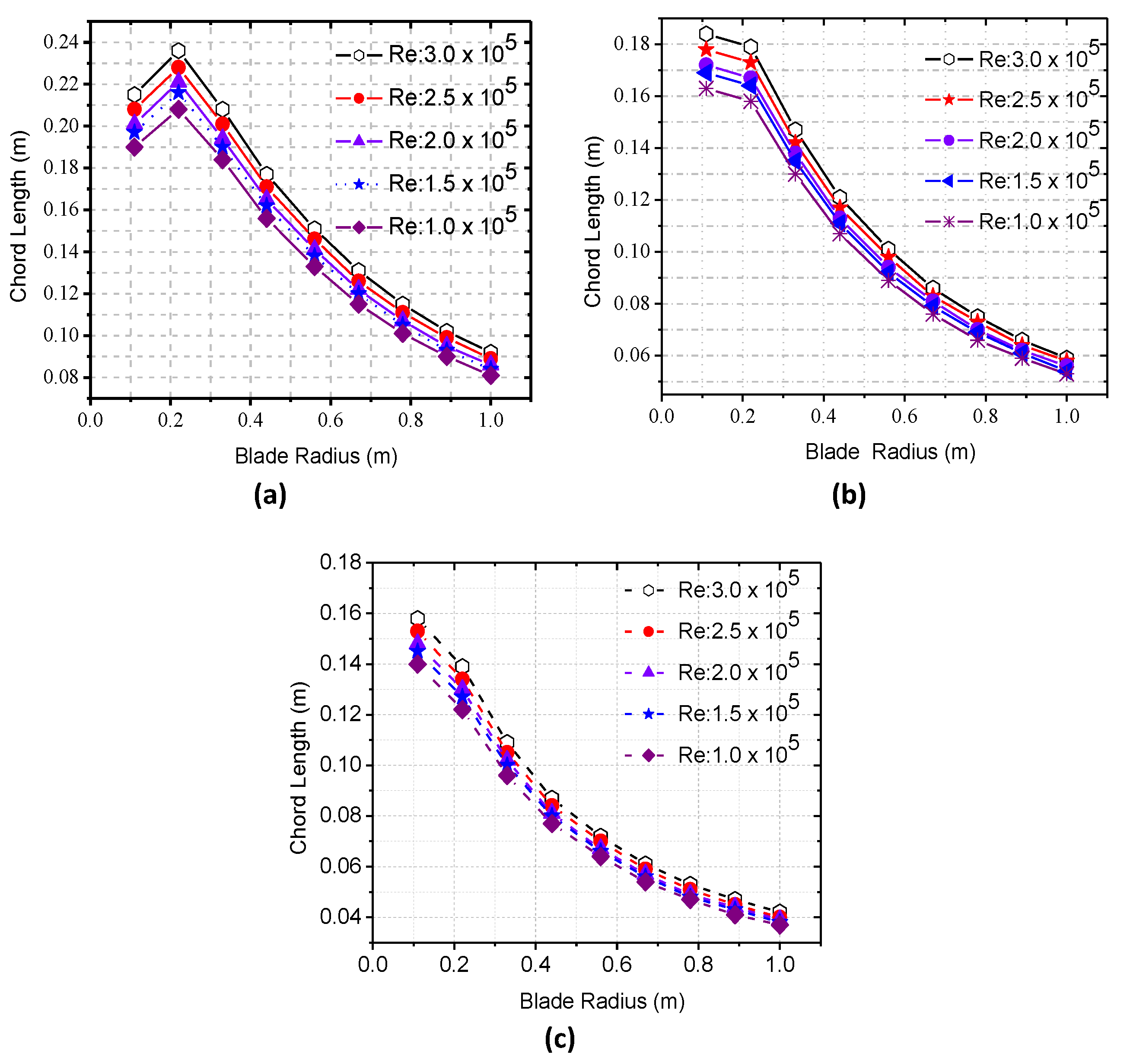
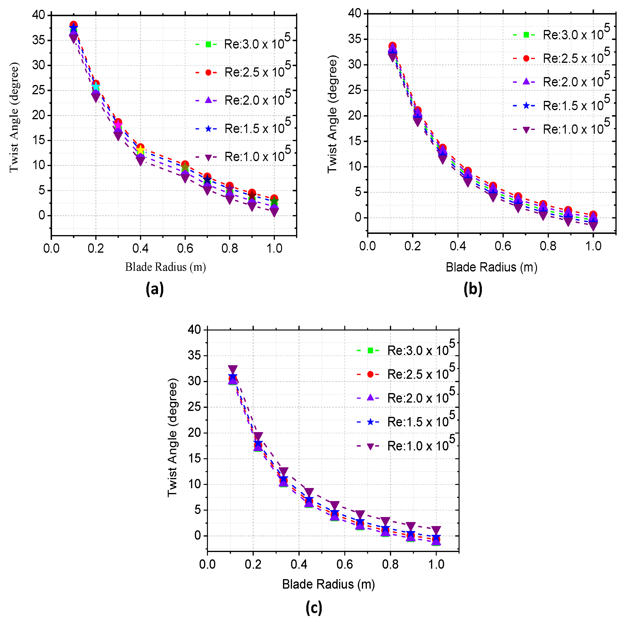
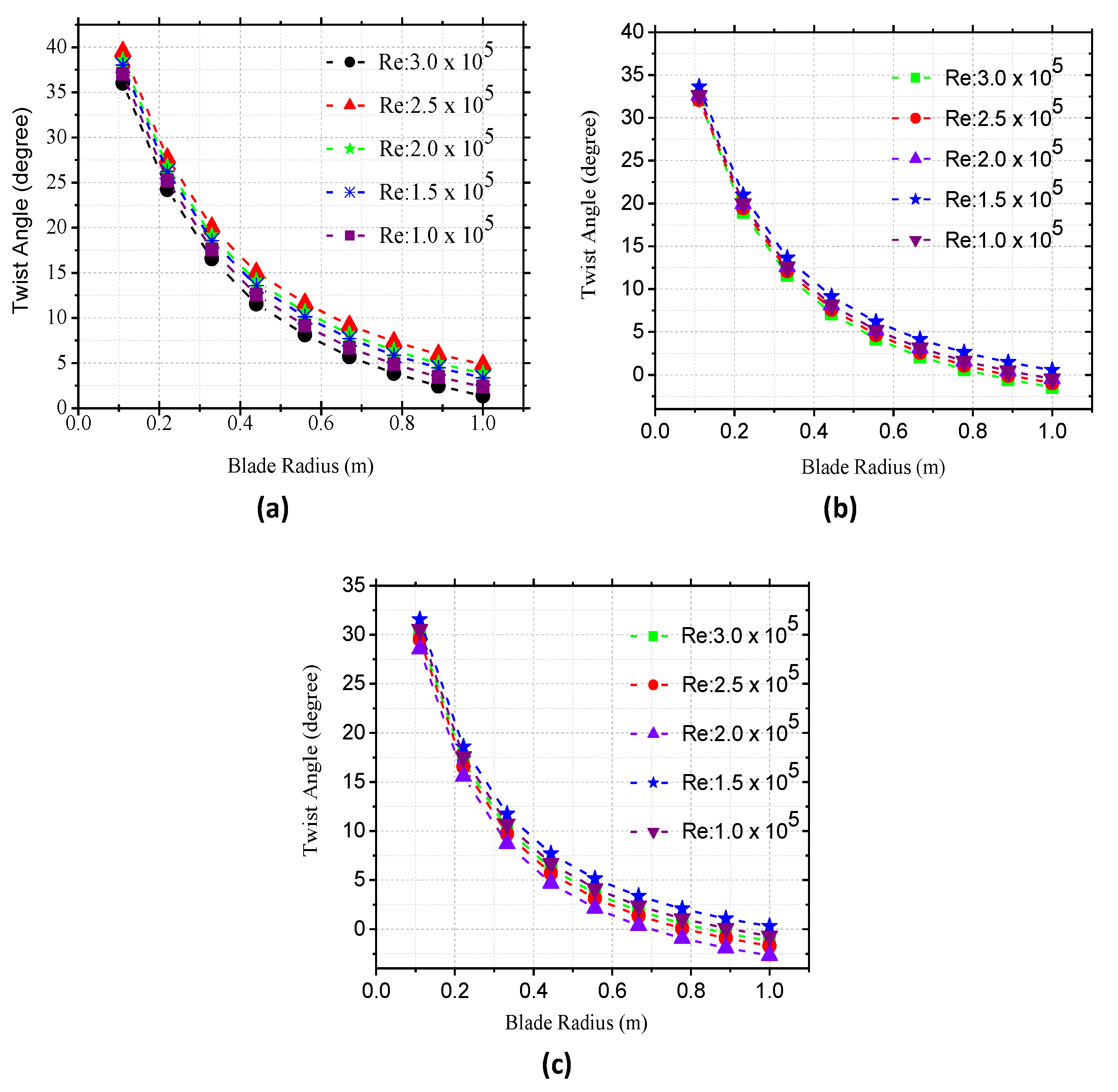
Relative wind angle, , is the angle between the blade plane of rotation and the relative wind velocity. The blade pitch angle, , is defined as the angle between the blade plane of rotation and chord line, while twist angle, , is the angle that shows the torsion of the blade which is the angle between the rotor plane and the chord line of the airfoil. It is defined mathematically by Equation (6). Here, the relative wind angle (φ) was found using Equation (3), and then substituted in Equation (4) to iteratively solve for optimum axial and angular induction factors, and , that will in turn be used in Equation (5) to obtain the optimum wind angle. Furthermore, the optimum twist angle () and chord distribution () along the blade radius were obtained using Equations (6) and (7). The results were then transferred to Q-blade software where the twist angles were further optimized. As presented in Figure 5, Figure 6, Figure 7 and Figure 8, the best twist and chord distributions that will yield the most optimum power coefficients for the two airfoils are obtained with angles of attack in the range of 5°–8° depending on the Re and TSR values.
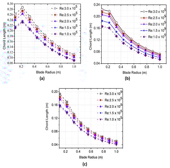
Figure 5.
Blade optimum chords distribution for NACA 4412 airfoil at (a) TSR 4; (b) TSR 5; (c) TSR 6.
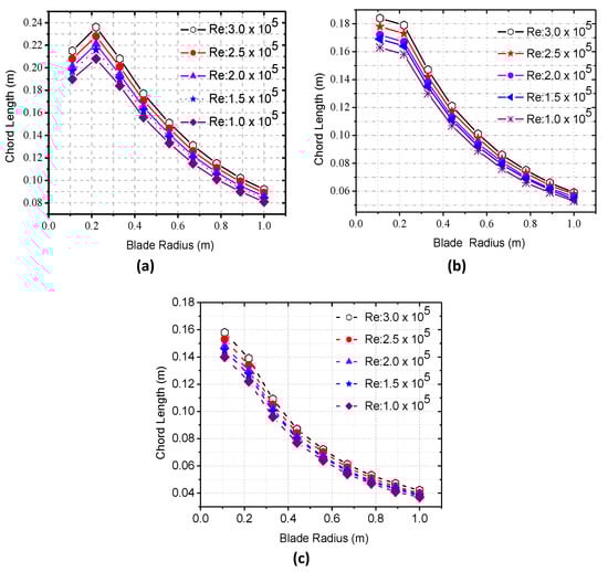
Figure 6.
Blade optimum chords distribution for SG6043 airfoil at (a) TSR 4; (b) TSR 5; (c) TSR 6.
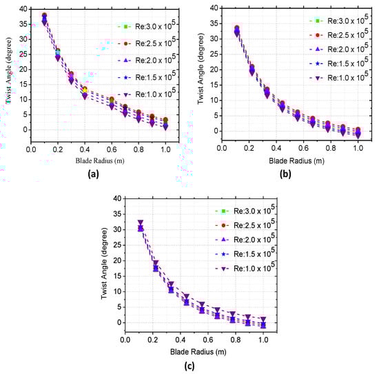
Figure 7.
Blade optimum twist distributions for NACA 4412 airfoil at (a) TSR 4; (b) TSR 5; (c) TSR 6.
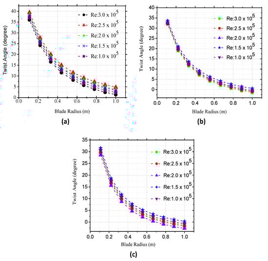
Figure 8.
Blade optimum twist distributions for SG6043 airfoil at de (a) TSR 4; (b) TSR 5; (c) TSR 6.
2.6. Velocity and Forces on Wind Turbine’s Blade
The relationship that defined the four angles as used in Equation (5) is presented in Figure 9.
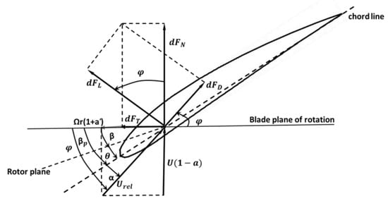
Figure 9.
Forces and velocities acting on WT airfoil and their angles.
From Figure 9, , is the section pitch angle, which defines as the angle between the plane of rotation and the chord line, , is the angle of attack which is the angle between the relative wind speed and the chord line. The forces: is the incremental tangential force which is responsible for producing the torque, is the force (incremental) normal to the blade plane of rotation which produces the thrust, and and are the incremental drag and lift forces [29,30,31].
3. Results and Discussion
3.1. Designed Rotor Blade
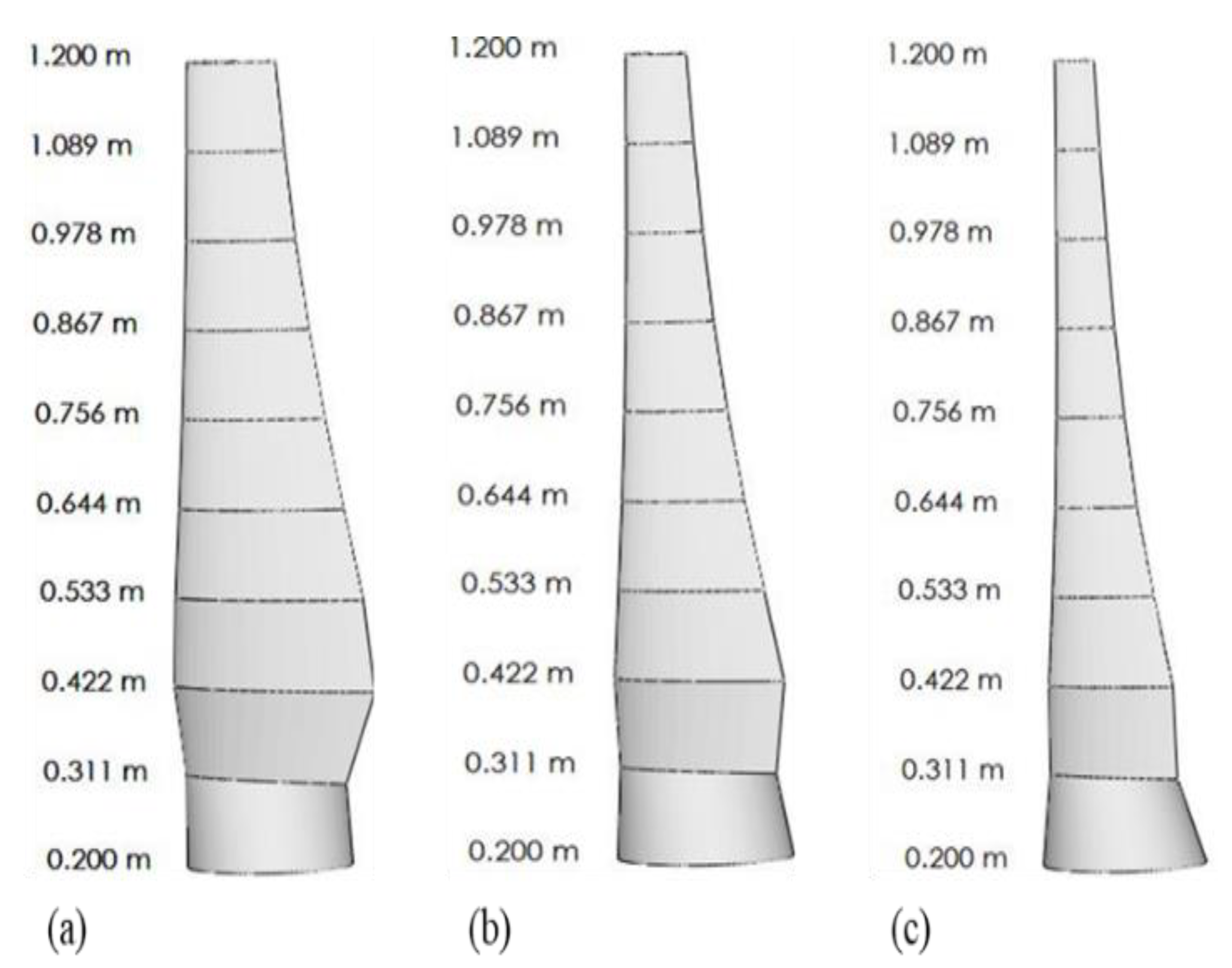
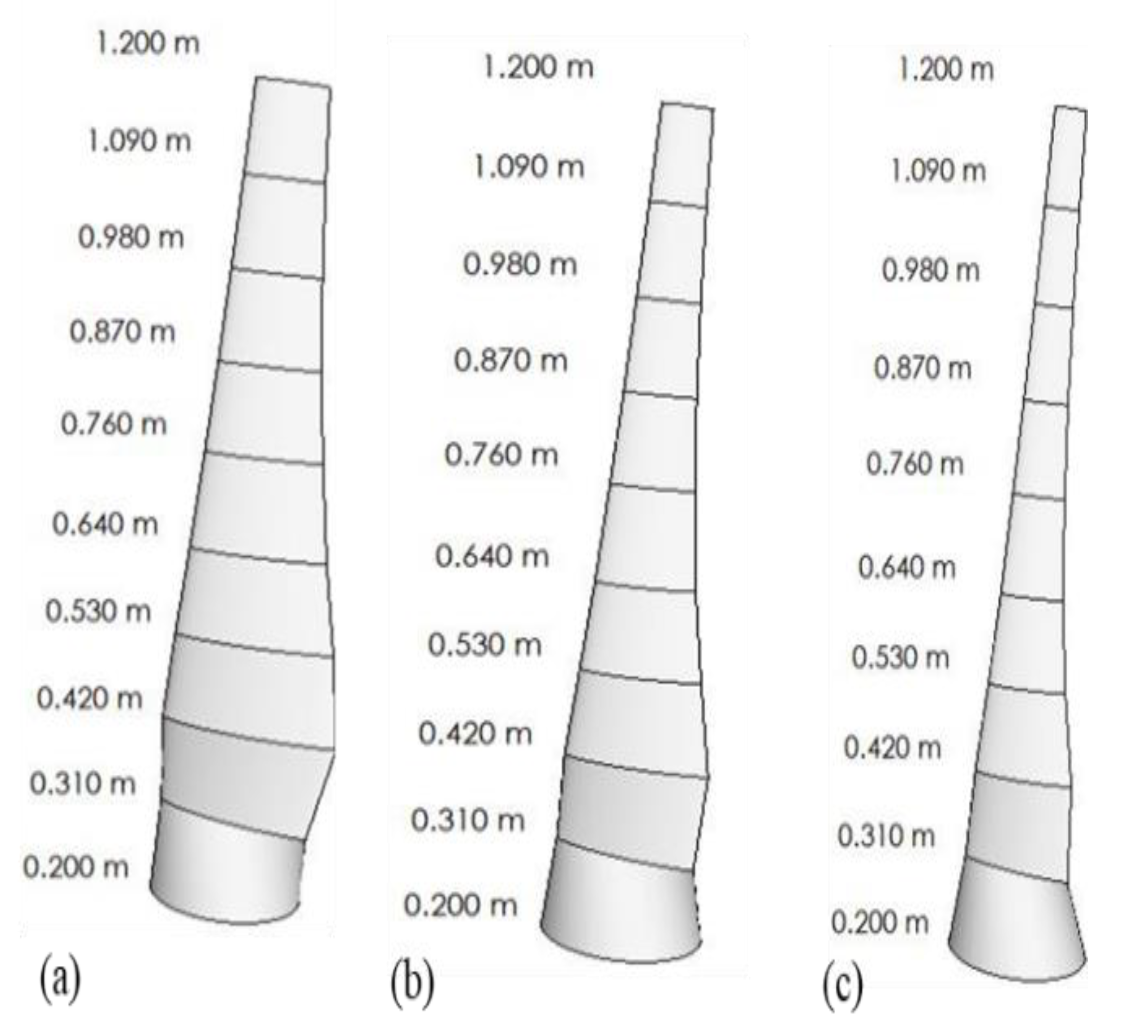
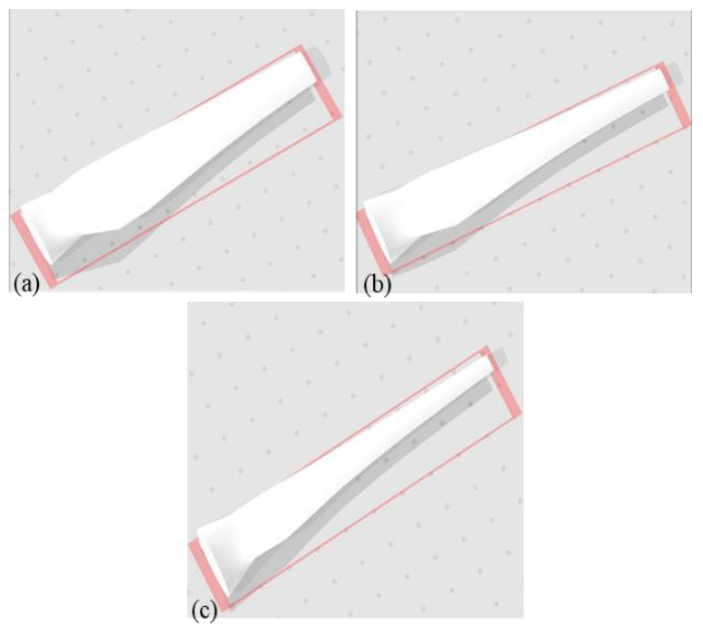
The XFOIL format of the designed rotor blade as obtained from the Q-blade is presented in Figure 10 and Figure 11, while the 3D format is depicted in Figure 12 and Figure 13. It can be seen that the blades at TSR 4 appeared to be broader, which is due to the high values of its chord length that resulted from the smaller size of design TSR value. Due to decreasing value of chord length distribution along the blades span, the blade becomes thinner from the root to the tip.
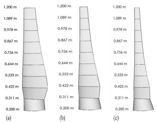
Figure 10.
Optimum blade designed with NACA 4412 airfoils for (a) TSR 4; (b) TSR 5; (c) TSR 6.
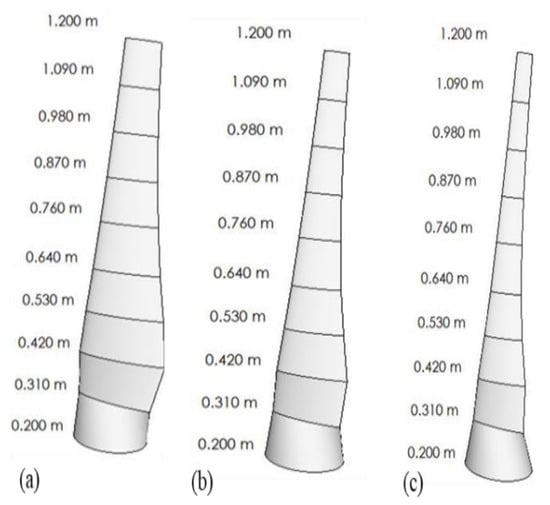
Figure 11.
Optimum blade designed SG6043 airfoils for (a) TSR 4; (b) TSR 5; (c) TSR 6.
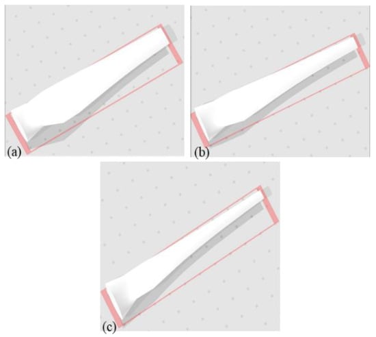
Figure 12.
3-D blade model designed with NACA 4412 airfoils for (a) TSR 4; (b) TSR 5; (c) TSR 6.
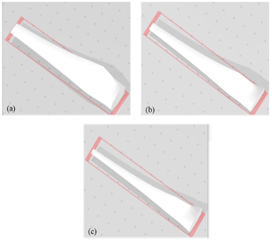
Figure 13.
3-D blade model designed with SG6043 airfoils for (a) TSR 4; (b) TSR 5; (c) TSR 6.
3.2. Power Coefficients
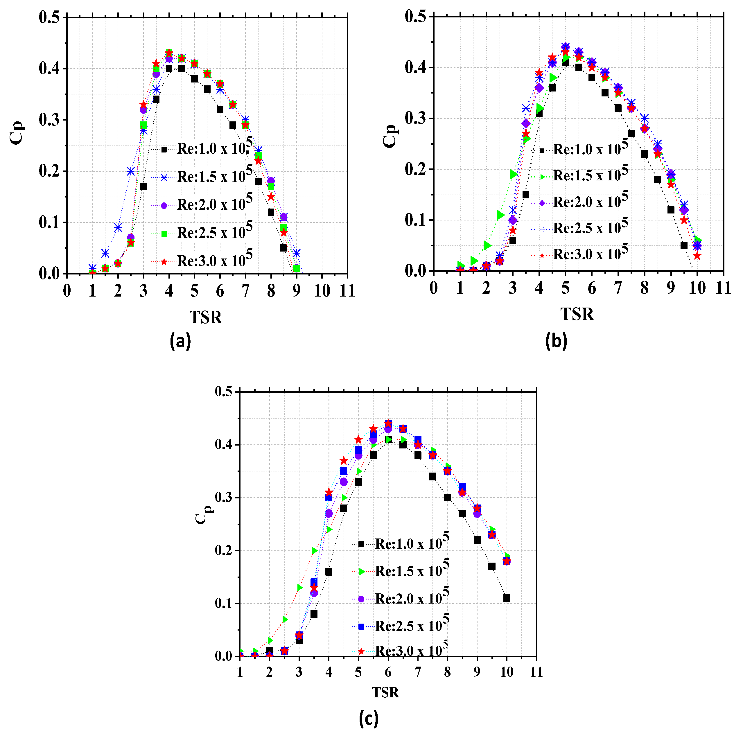
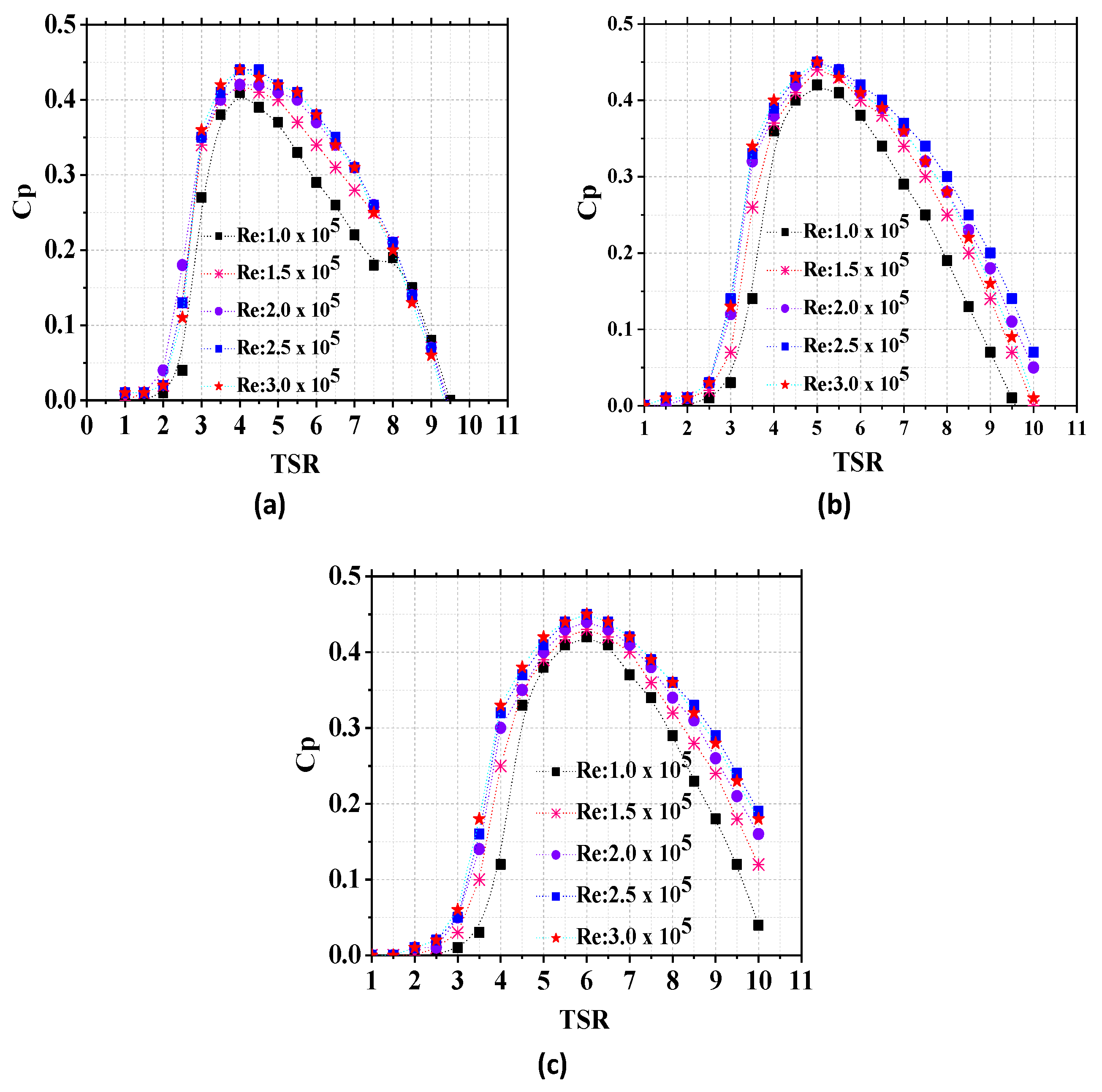
Figure 14 and Figure 15 show the results of blade performance in terms of power coefficient at the Re of , , , , and for different TSRs values (1–11). It is observed that the blade efficiencies increased with the increasing Re. The highest efficiency values were obtained at Re of for each of the TSR. Moreover, in all cases, maximum efficiency values were obtained at the design TSR of 6. For instance, in Figure 15a–c, the SG6043 rotor has the highest efficiency of 0.43 at the TSR of 4, 0.44 at the TSR of 5, and 0.45 at the TSR of 6, whereas in the case of NACA 4412 rotor (Figure 14a–c), the highest efficiency values were recorded as 0.42, 0.43, and 0.44 for the TSR of 4, 5, and 6 respectively.

Figure 14.
Power coefficients obtained with NACA 4412 rotor blades for (a) TSR 4 (b) TSR (5) (c) TSR 6.
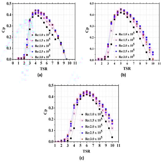
Figure 15.
Power coefficients obtained with SG6043 rotor blades for (a) TSR 4 (b) TSR (5) (c) TSR 6.
3.3. Cut-in Wind Speed
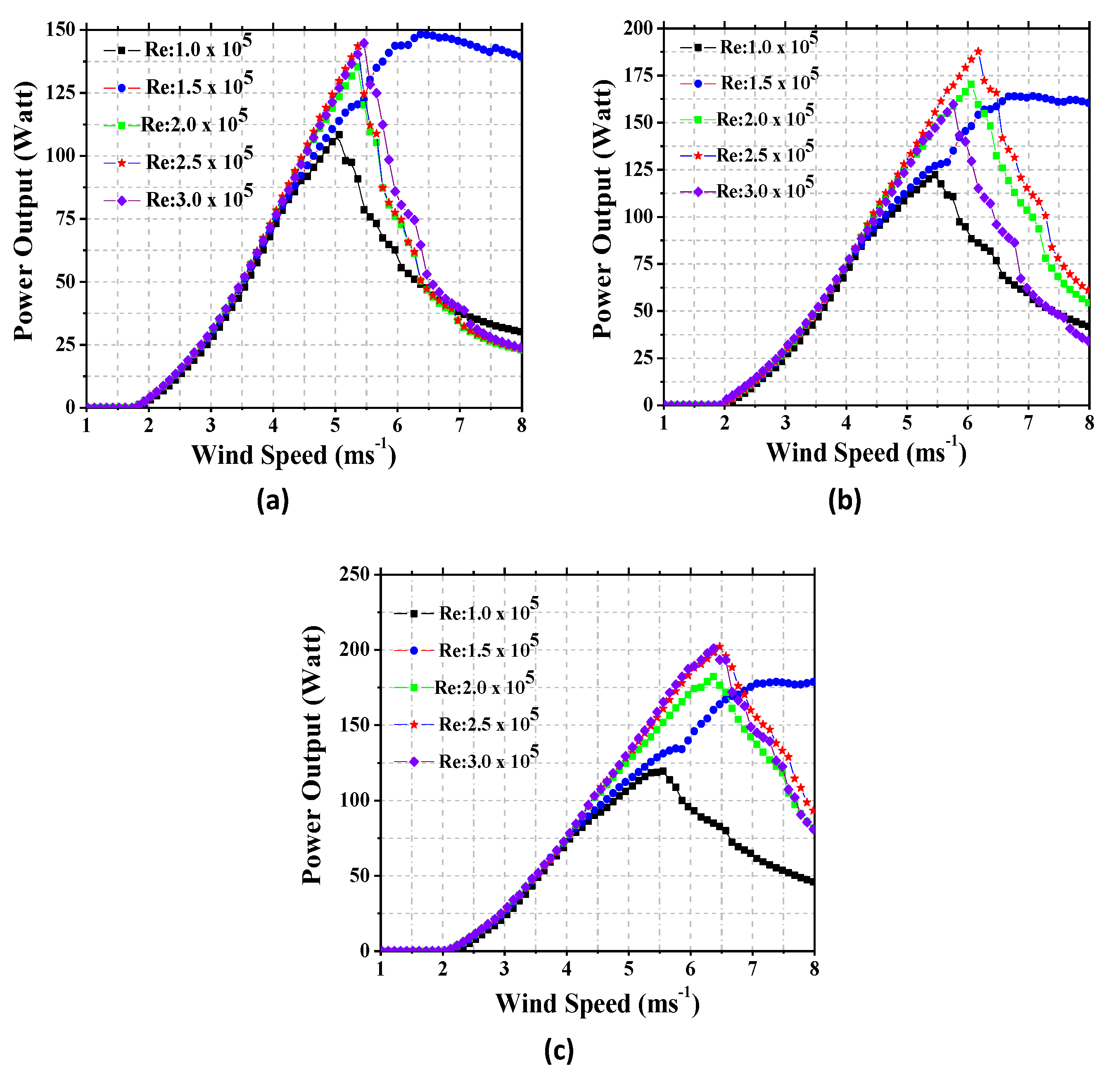
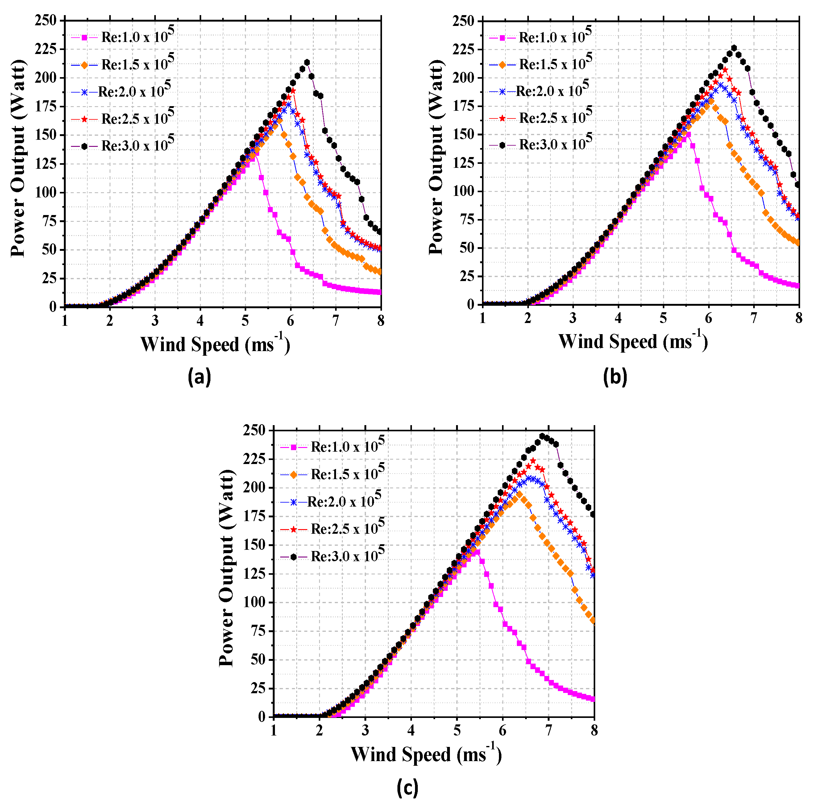
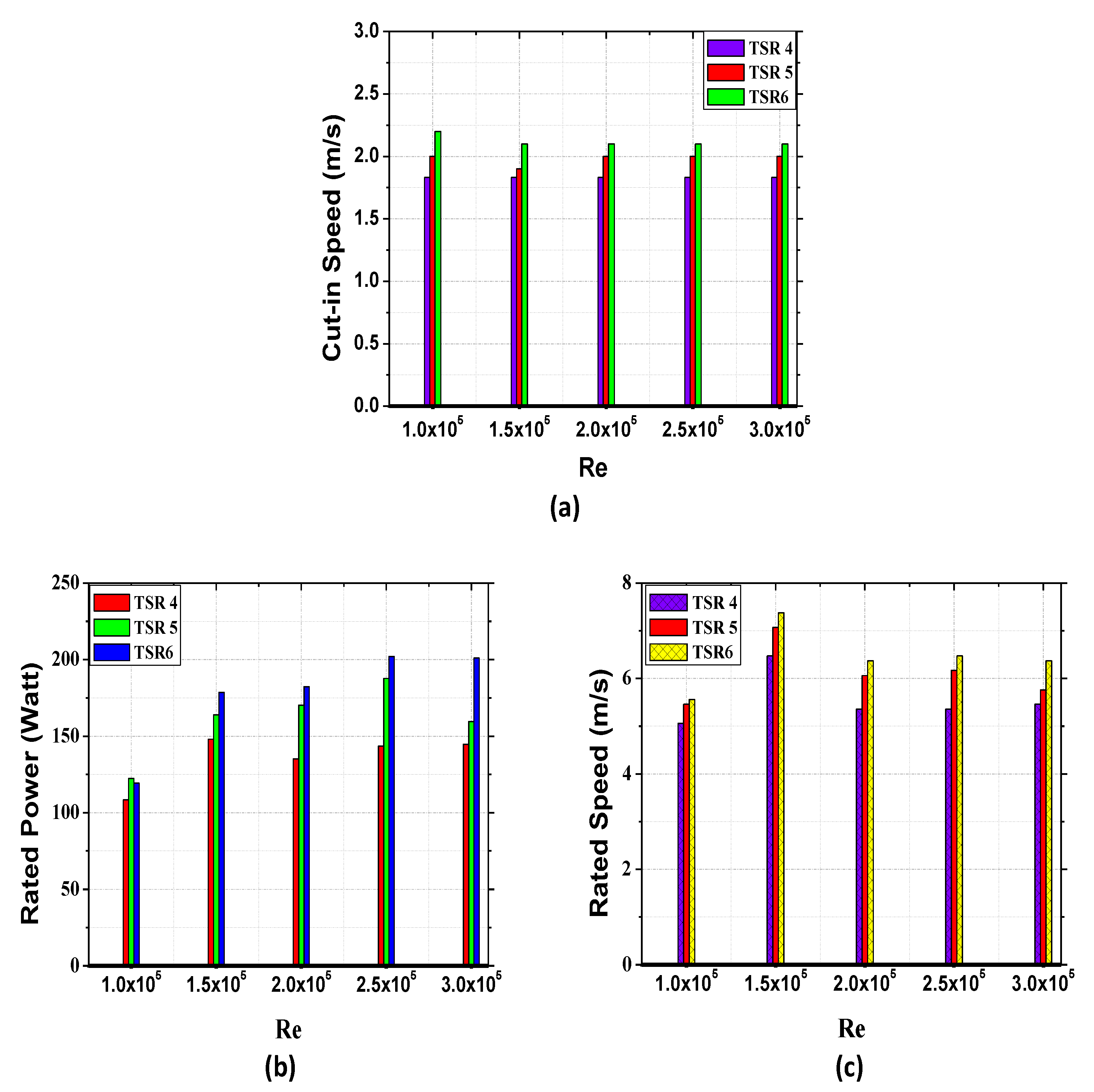
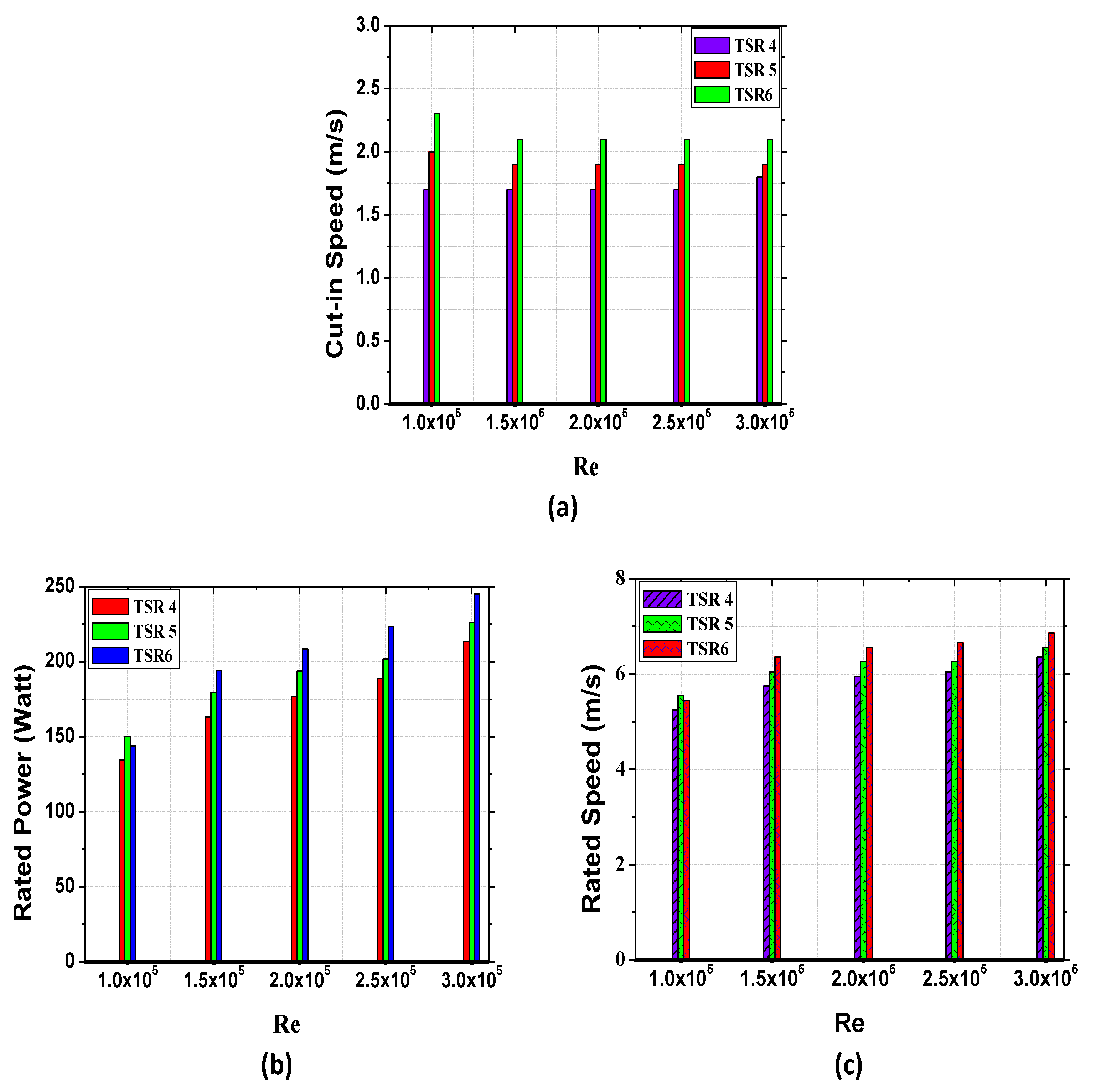
The results of rotor blade power simulations carried out for wind speeds from 0–8 m/s are presented in Figure 16 and Figure 17 for NACA 4412 and SG6043 airfoils, respectively, while Figure 18a and Figure 19a present the summary of values for the cut-in speed at different TSR and Re for both the two rotor blades. It was observed that the WT cut-in speeds (wind speed at which the rotor blade starts to produce power), for the two airfoils, depend on the value of TSR and Re. As displayed in Figure 16a and Figure 17a, the lowest cut-in speed of 1.80 m/s and 1.70 m/s were observed at the TSR 4 for NACA 4412 and SG6043. For the NACA 4412 rotor blade, the lowest cut-in speed occurred at Re of , , and . As for the SG6043 rotor blade, this occurred at all Re values. The cut-in speed further increased to 2.0 m/s (for NACA 4412) and 1.90 m/s (for SG6043), as indicated in Figure 16b and Figure 17b, when the TSR is increased to 5. At the TSR 6, as shown in Figure 16c, the cut-in speed for the NACA 4412 blade increased more to 2.13 m/s for all the Re, except at , where the cut-in speeds reached a value of 2.20 m/s. In the case of the SG6043 blade, as shown in Figure 17c, the cut-in speeds showed the same value (2.10 m/s) at the TSR 6 for Re of and , while for Re of the value is 2.3 m/s.
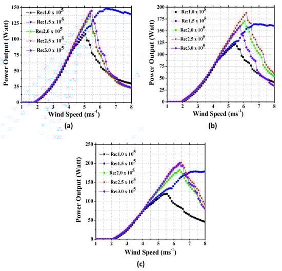
Figure 16.
Power output for NACA 4412 at design (a) TSR 4; (b) TSR 5; (c) TSR 6.
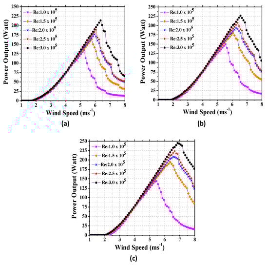
Figure 17.
Power output for SG6043 at design (a) TSR 4; (b) TSR 5; (c) TSR 6.
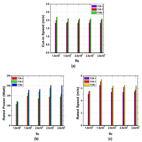
Figure 18.
(a) Cut-in speeds; (b) Rated powers; (c) Rated speeds for NACA 4412 rotor blades.
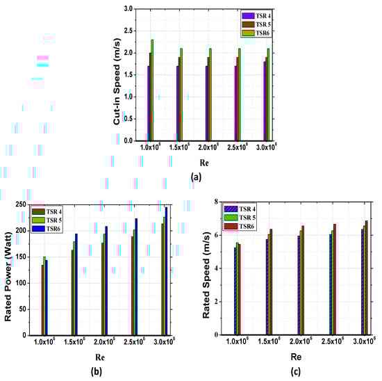
Figure 19.
(a) Cut-in Speeds; (b) Rated powers; (c) Rated Speeds for SG6043 rotor blade.
3.4. Rated Powers and Rated Speeds
From Figure 16 and Figure 17, it is observed that, similar to the cut-in speeds, the rated power and the rated speeds for the two airfoils also change with Re and the TSR values. From Figure 18b,c, for the TSR of 4, it can be seen that the highest-rated power occurred at Re of for both the rotor blades. In the case of the NACA 4412 rotor blade, power as high as 144.3 W value was recorded at the lowest rated wind speed of 5.46 m/s. As for the case of SG6043 which is shown in Figure 19b,c, with a small increase in the wind speed to 6.36 m/s, the rated power increased to a peak value of 213.55 W. The rated power is appreciated more when the TSR is increased to 5 for both rotors, as depicted in Figure 16b and Figure 17b. As presented further in Figure 18b,c and Figure 19b,c the highest-rated powers were achieved at the Re of for NACA 4412 rotor blades, and SG6043 occurred at Re of . SG6043 recorded the highest power value of 226.44 W at a rated wind speed of 6.56 m/s, while NACA 4412 recorded 187.76 m/s as the highest-rated power at the wind speed of 6.17 m/s. The highest rotor blade power harvesting performance was obtained at the TSR 6, and 201.04 and 245.092.95 W highest rated powers value were obtained respectively with NACA 4412 W (Figure 16c and Figure 18b) and SG6043 (Figure 17c and Figure 19b). The rated speeds were 7.17 for NACA 4412 (Figure 18c) and 8.28 m/s for SG6043 (Figure 19c).
3.5. Powers Output at Design Wind Speed
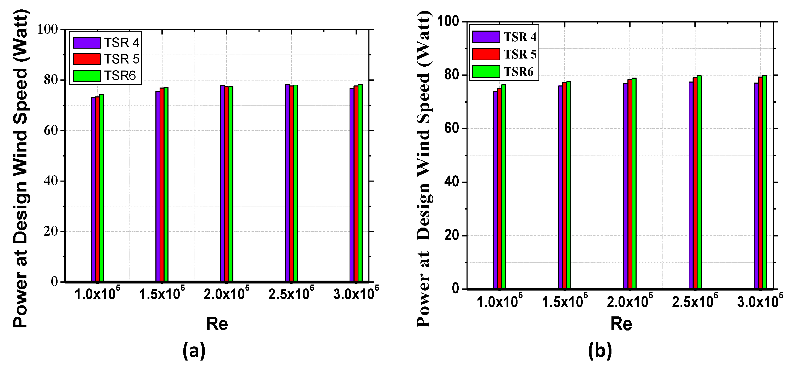
The power generated by the rotor blades at a design wind speed of 4 m/s is shown in Figure 20a,b (which were extracted from Figure 16 and Figure 17). It was noticed that at lower wind speed ranging from the cut-in speed up to just before the design wind speed, the output power increased with decreasing TSR and increasing Re. It is clearly shown that more powers are generated at the highest Re, and it is even more so at the lowest TSR value of 4. The highest values of power obtained at low wind speed are due to the fact that the turbine with a low value of TSR is expected to generate more torque and hence more power. The power harvested reaches up to 78.29 W with NACA 4412 rotor (Figure 20a) and 79.3 W with SG6043 rotor (Figure 20b) at the TSR value 4 and design wind speed of 4 m/s. Less power with the highest value of 77.70 W was obtained with NACA 4412 rotor blade (Figure 16b and Figure 20a), and 79.2 W was obtained with SG6043 (Figure 17b and Figure 20b) rotor blades, respectively, when the TSR value increased to 5. As the TSR reached the value of 6, the highest power harvested at the design wind speed appreciated to 78.33 W and 80.10 W values (Figure 20a,b).
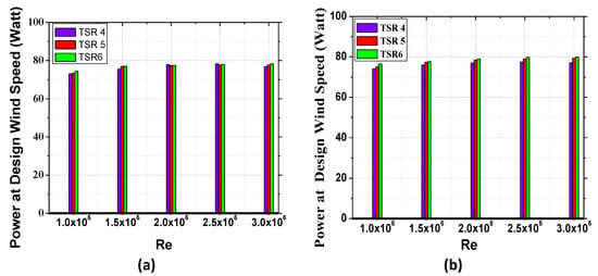
Figure 20.
Power output at design wind speed (a) NACA 4412 rotor blade (b) SG6043 rotor blade.
3.6. Results Validation
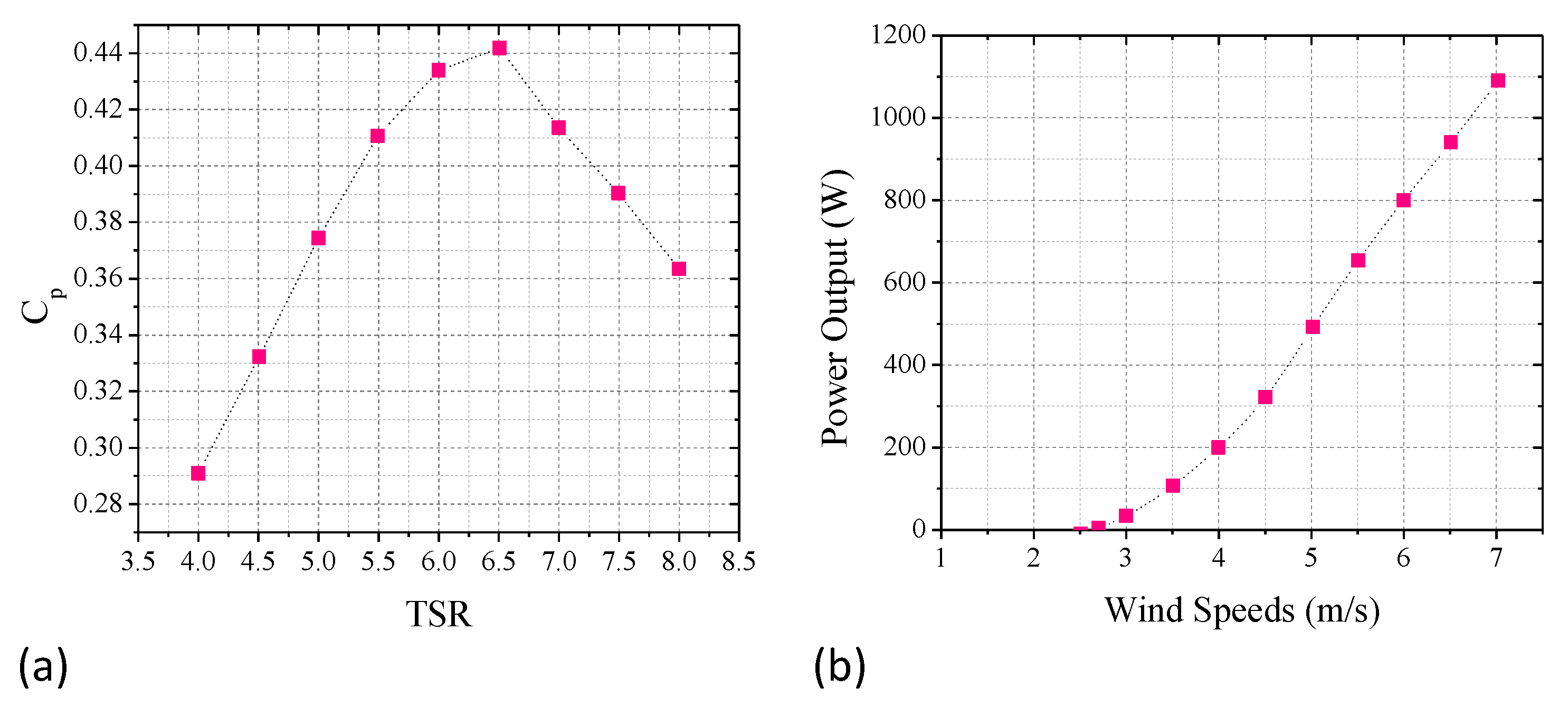
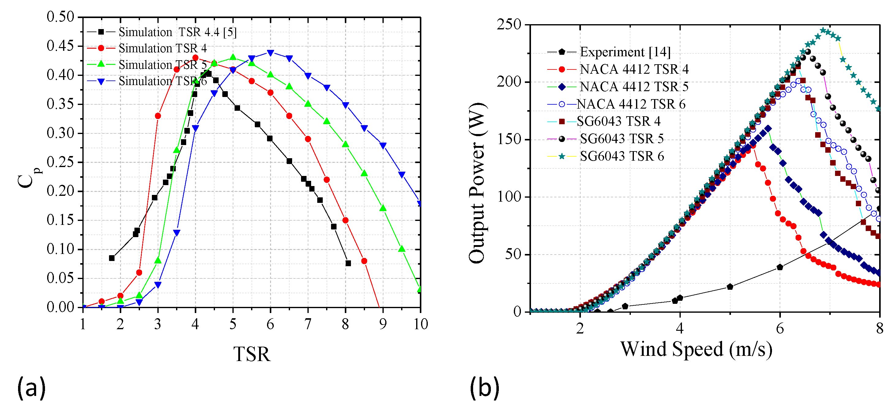
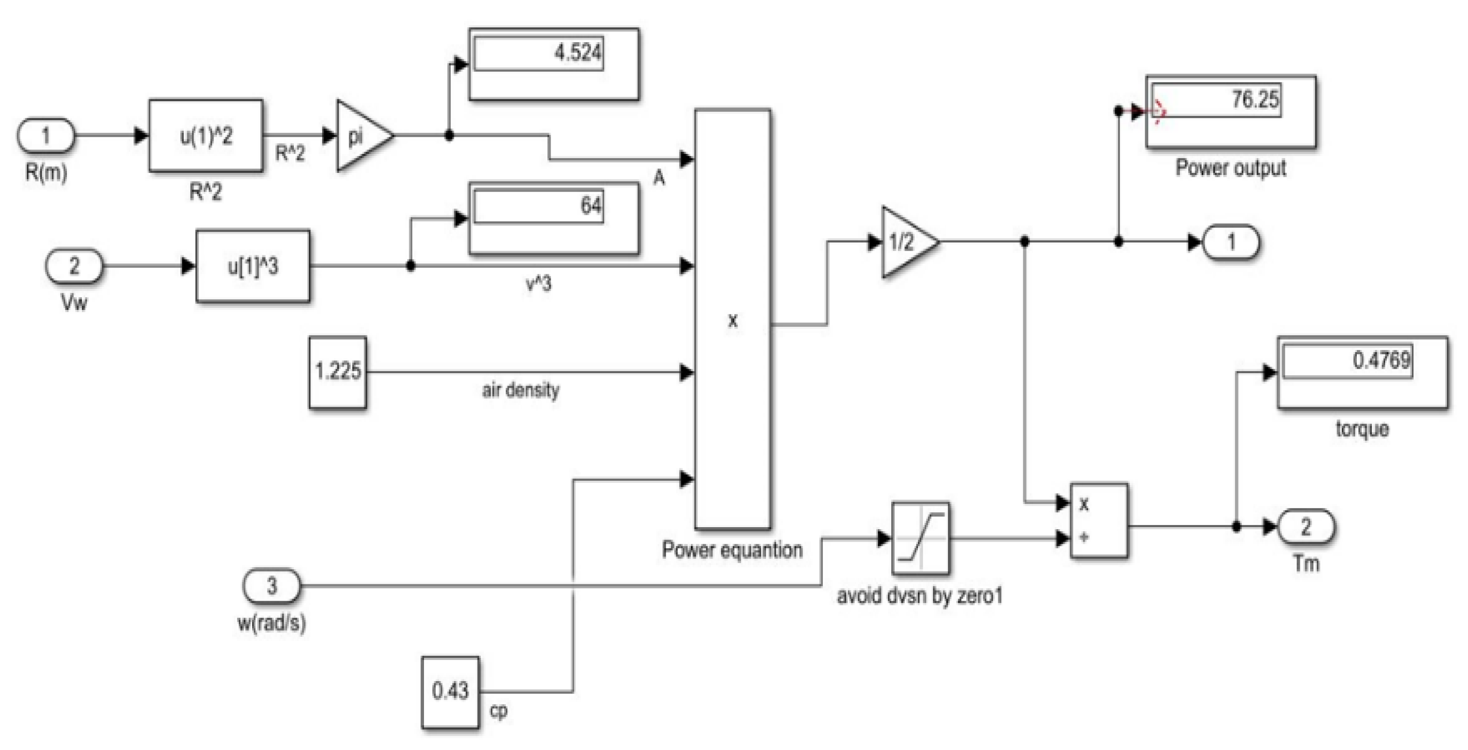
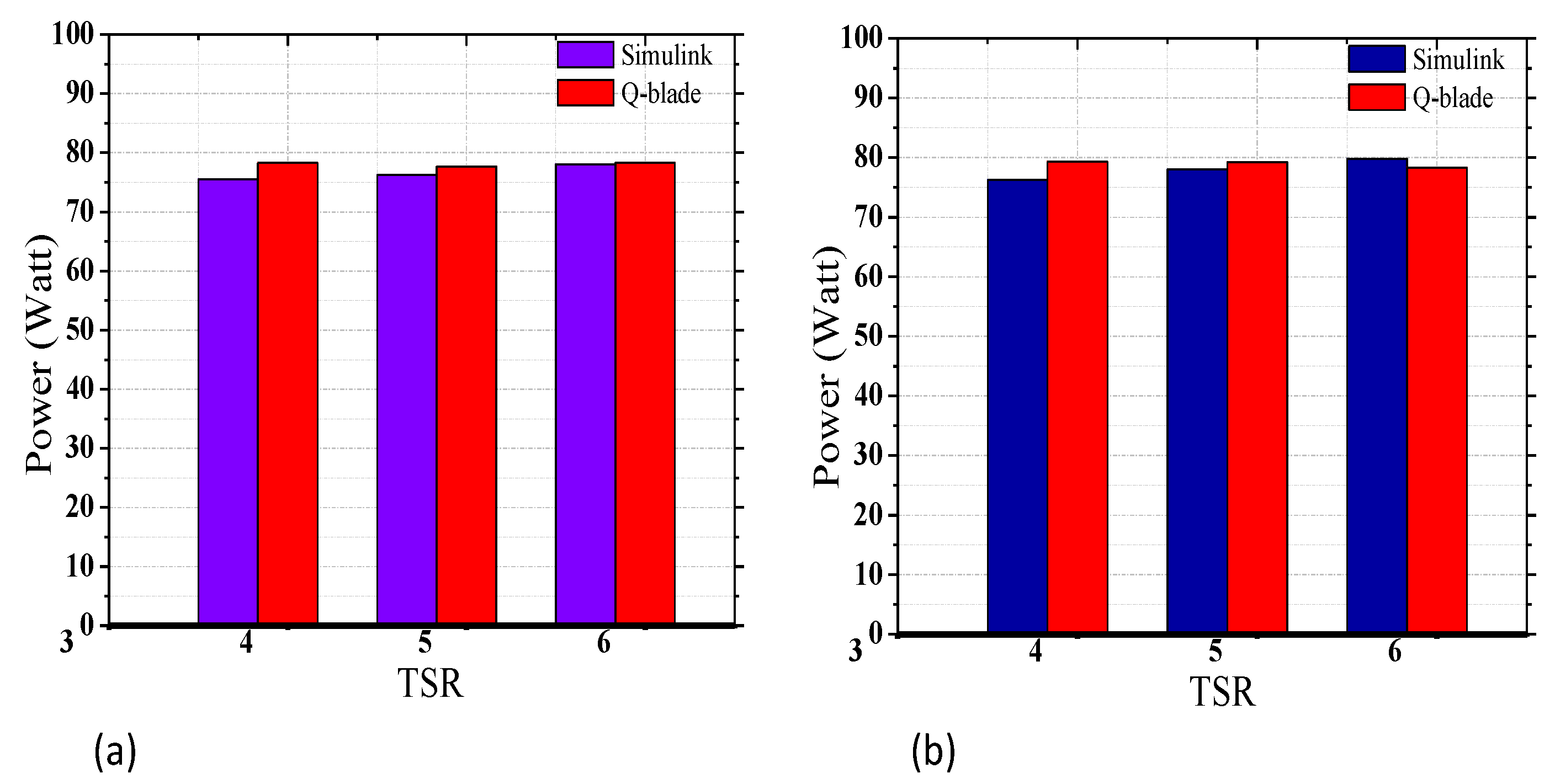
To validate the proposed approach, our results have been compared with other results obtained from previous theoretical and experimental works, and are found to be in good agreement. Both the present and compared works were performed under similar conditions. In the simulation work performed by Muhsen, et al. [4], a blade of two meters in length was considered, and the design and optimization were carried out under wind speed of 5.5 m/s. The results obtained in terms of power coefficient are presented in Figure 21a, and those obtained in terms of output power and cut-in speed were depicted in Figure 21b. At a wind speed of 4 m/s, which is similar to our design wind speed, the output power recorded was approximately 200 W (Figure 21b). Figure 22a,b compares our results with the results of Akour, et al. [14], which was obtained experimentally in an open-air environment. In the case of [14], the blade length and TSR were 0.5 m and 3.5 respectively, and the design wind speed was 5.5 m/s. Due to the small-sized of blade length and TSR value, the power coefficient was obtained as 0.34. The power coefficients as compared are given in Figure 22a. The compared output powers and cut-in speed recorded is presented in Figure 22b. The results have also been verified in MATLAB/Simulink environment (Figure 23), using the obtained power coefficients, design wind speed, blade length TSR, and rotational speed as the inputs signal. Figure 23 depicts the MATLAB Simulink set-up, while in Figure 24, the outpowers are presented for the two airfoils rotor blades. These two results are found to be similar and consistent.
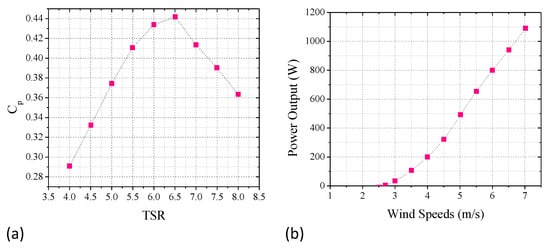
Figure 21.
(a) Power coefficient; (b) output power Muhsen, et al. [14].
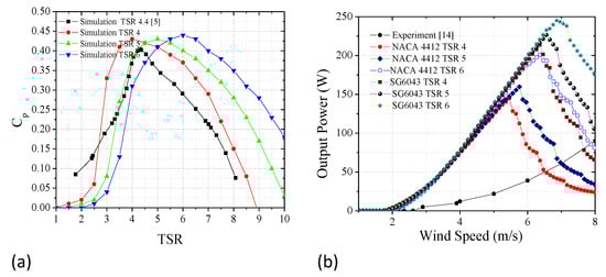
Figure 22.
Comparison of (a) power coefficients; (b) output powers [14].
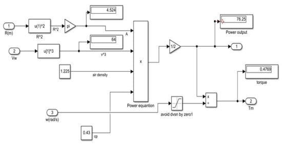
Figure 23.
WT power simulation set-up with MATLAB/ Simulink for validation.
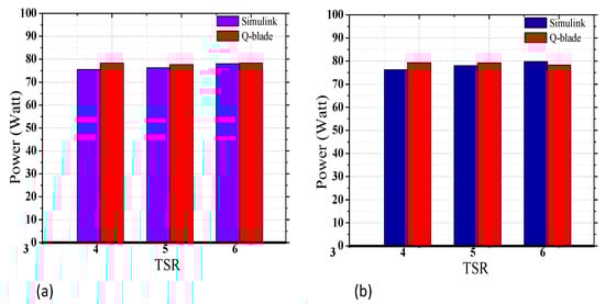
Figure 24.
Compared power output at design wind speeds obtained with Q-blade and MATLAB/ Simulink for (a) NACA 4412 rotor blade (b) SG6043 rotor blade.
4. Conclusions
In this work, the design of small horizontal axis wind turbine blades was performed using blade element momentum theory. A total of three blades were considered, and the blade pitch angle was kept constant at 0° angle throughout the power simulations. Calculations of the parameters for the design were achieved by employing MATLAB software, while the remaining tasks, such as airfoils analysis, rotor blade design, and power simulation, were performed using Q-blade software. Overall, four digit airfoils of NACA 4412 and SG6043 were considered, and analysis was performed at varying Re of , , , , and . The highest power coefficients were obtained at the Re of for all the TSR values (4,5, and 6). However, the highest value of power coefficient and power output was obtained at TSR 6. Power coefficients values of 0.42, 0.43, and 0.44 were achieved with NACA 4412 rotor blades, while power coefficient values of 0.43, 0.44, and 0.45 were realized with SG6043 rotor blades at the TSR 4, 5, and 6. Moreover, at the TSR 4, 5, and 6, the blades were able to harvest powers of up to 144.73 watts (W), 159.69 W, and 201.04 W with the NACA 4412, and 213.15 W, 226.44 W, and 245.09 W with the SG6043 blades. Moreover, the main admirable achievement of this work is that the design blades were able to harvest wind powers of 79.3 W and 80.10 W at the design wind speed of 4 m/s with the NACA 4412 and SG6043 rotor blades, respectively. In addition, at TSR 4, both the NACA 4412 and SG6043 rotor blades exhibited the lowest cut-in speed of 1.80 m/s and 1.70 m/s, respectively. These represent the best result ever obtained with a 1-m radius length rotor blade at the low wind speed of 4 m/s.
Based on the above findings, it is therefore concluded that the two airfoils are good candidates for small WT blades for optimum energy harvesting from low wind speed areas. Furthermore, rotor blades of Re and for both the two airfoils are considered the best in terms of efficiency and power harvesting performance. However, in terms of fast response and good performance at lower wind speeds, the rotor blades of TSR 4 at Re are the best option.
It is recommended that work should be carried out on how to connect the designed blade with suitable electrical generators and other peripherals. The work can be extended to study how to integrate the output powers of the individuals and groups of WTs for off-grid application. It is further recommended that optimum connection configuration and layout between individuals and groups of WTs should be studied to find the least inter-distance between the individuals and groups of WTs that will yield optimum overall power output and minimum power loss arising from wake rotation.
Author Contributions
Conceptualization, D.A.U., S.P.K. and S.K.T.; methodology, D.A.U., S.P.K., S.K.T. and A.A.A.; software, D.A.U.; validation, D.A.U., S.P.K., S.K.T. and A.A.A.; formal analysis, D.A.U., S.P.K., S.K.T. and A.A.A.; investigation, D.A.U.; resources, D.A.U. and A.A.A.; data curation, D.A.U.; writing—original draft preparation, D.A.U., C.T.Y. and S.P.K.; writing—review and editing, D.A.U., C.T.Y., S.P.K. and T.Y.; visualization, S.P.K., S.K.T. and A.A.A.; supervision, C.T.Y., S.P.K. and S.K.T.; project administration, S.P.K., S.K.T. and A.A.A.; funding acquisition, S.P.K. and S.K.T. All authors have read and agreed to the published version of the manuscript.
Funding
This research was funded by BOLDREFRESH 2025 (RJO10517844/052 and J510050002 (IC-6C)).
Acknowledgments
The authors also acknowledge the contribution of the facilities of Universiti Tenaga Nasional Sdn. Bhd, Malaysia (UNITEN) and BOLDREFREASH 2025 for providing all out-laboratory support.
Conflicts of Interest
The authors declare no conflict of interest.
References
- Karthikeyan, N.; Murugavel, K.K.; Kumar, S.A.; Rajakumar, S. Review of aerodynamic developments on small horizontal axis wind turbine blade. Renew. Sustain. Energy Rev. 2015, 42, 801–822. [Google Scholar] [CrossRef]
- Buaossa, N.; Aldricy, M.; Ragab, K.; Rajab, Z.; Tahir, A.; Khalil, A. Practical design and performance evaluation of micro-wind turbine in Libya. In Proceedings of the 2018 9th International Renewable Energy Congress (IREC), Hammamet, Tunisia, 24 May 2018; pp. 1–6. [Google Scholar]
- Abbas, U.D.; Tiong, S.; Alkahtani, A.A.; Chen, C.; Alkawsi, G.; Ekanayake, J. Power Curve Evaluation of Micro-Scale Turbines for Harvesting Wind Energy in Malaysia. Appl. Math. Inf. Sci. 2021, 15, 59–71. [Google Scholar] [CrossRef]
- Muhsen, H.; Al-Kouz, W.; Khan, W. Small wind turbine blade design and optimization. Symmetry 2020, 12, 18. [Google Scholar] [CrossRef] [Green Version]
- Purusothaman, M.; Valarmathi, T.; Reddy, S.P. Selection of twist and chord distribution of horizontal axis wind turbine in low wind conditions. In IOP Conference Series: Materials Science and Engineering; IOP Publishing: Bristol, UK, 2016; Volume 149, p. 012203. [Google Scholar]
- Singh, R.K.; Ahmed, M.R. Blade design and performance testing of a small wind turbine rotor for low wind speed applications. Renew. Energy 2013, 50, 812–819. [Google Scholar] [CrossRef]
- Kale, S.A.; Varma, R.N. Aerodynamic design of a horizontal axis micro wind turbine blade using NACA 4412 profile. Int. J. Renew. Energy Res. 2014, 4, 69–72. [Google Scholar]
- Chaudhary, M.K.; Roy, A. Design & optimization of a small wind turbine blade for operation at low wind speed. World J. Eng. 2015, 12, 83–94. [Google Scholar] [CrossRef]
- Hsiao, F.-B.; Bai, C.-J.; Chong, W.-T. The performance test of three different horizontal axis wind turbine (HAWT) blade shapes using experimental and numerical methods. Energies 2013, 6, 2784–2803. [Google Scholar] [CrossRef] [Green Version]
- Rehman, S.; Alam, M.; Alhems, L.M.; Rafique, M.M. Horizontal axis wind turbine blade design methodologies for efficiency enhancement—A review. Energies 2018, 11, 506. [Google Scholar] [CrossRef] [Green Version]
- Prasad, E.N.; Janakiram, S.; Prabu, T.; Sivasubramaniam, S. Design and development of horizontal small wind turbine blade for low wind speeds. J. Eng. Sci. Adv. Technol. 2014, 4, 75–84. [Google Scholar]
- Lanzafame, R.A.; Messina, M. Fluid dynamics wind turbine design: Critical analysis, optimization and application of BEM theory. Renew. Energy 2007, 32, 2291–2305. [Google Scholar] [CrossRef]
- Scappatici, L.; Bartolini, N.; Castellani, F.; Astolfi, D.; Garinei, A.; Pennicchi, M. Optimizing the design of horizontal-axis small wind turbines: From the laboratory to market. J. Wind. Eng. Ind. Aerodyn. 2016, 154, 58–68. [Google Scholar] [CrossRef]
- Akour, S.N.; Al-Heymari, M.; Ahmed, T.; Khalil, K.A. Experimental and theoretical investigation of micro wind turbine for low wind speed regions. Renew. Energy 2018, 116, 215–223. [Google Scholar] [CrossRef]
- Manwell, J.F.; McGowan, J.G.; Rogers, A.L. Wind Energy Explained: Theory, Design and Application, 2nd ed.; John Wiley & Sons Ltd.: Chichester, UK, 2010. [Google Scholar]
- Tahani, M.; Kavari, G.; Masdari, M.; Mirhosseini, M. Aerodynamic design of horizontal axis wind turbine with innovative local linearization of chord and twist distributions. Energy 2017, 133, 572–583. [Google Scholar] [CrossRef]
- Zhu, F.; Ding, L.; Huang, B.; Bao, M.; Liu, J. Blade design and optimization of a horizontal axis tidal turbine. Ocean Eng. 2020, 195, 106652. [Google Scholar] [CrossRef]
- Khan, S.; Amin, S.; Sabir, S.; Bukhari, H. Design and Comparative Performance Analysis of Inner Rotor and Inner Stator Axial Flux Permanent Magnet Synchronous Generator for Wind turbine Applications. In Proceedings of the 2019 2nd International Conference on Computing, Mathematics and Engineering Technologies (iCoMET), Sukkur, Pakistan, 30–31 January 2019; pp. 1–7. [Google Scholar]
- Kim, T.; Lee, S.; Kim, H.; Lee, S. Design of low noise airfoil with high aerodynamic performance for use on small wind turbines. In Science in China Series E: Technological Sciences; Springer: Berlin/Heidelberg, Germany, 2010; Volume 53, pp. 75–79. [Google Scholar]
- El-Okda, Y.; Adref, K.; Chikhalsouk, M.; Al Hajjar, H. Design of a Small Horizontal Axis Wind Turbine. In Proceedings of the 2019 Advances in Science and Engineering Technology International Conferences (ASET), Dubai, United Arab Emirates, 26 March–10 April 2019; pp. 1–7. [Google Scholar] [CrossRef]
- Hassanzadeh, A.; Hassanabad, H.; Dadvand, A. Aerodynamic shape optimization and analysis of small wind turbine blades employing the Viterna approach for post-stall region. Alex. Eng. J. 2016, 55, 2035–2043. [Google Scholar] [CrossRef] [Green Version]
- Shen, X.; Yang, H.; Chen, J.; Zhu, X.; Du, Z. Aerodynamic shape optimization of non-straight small wind turbine blades. Energy Convers. Manag. 2016, 119, 266–278. [Google Scholar] [CrossRef] [Green Version]
- Sanaye, S.; Hassanzadeh, A. Multi-objective optimization of airfoil shape for efficiency improvement and noise reduction in small wind turbines. J. Renew. Sustain. Energy 2014, 6, 053105. [Google Scholar] [CrossRef] [Green Version]
- Balijepalli, R.; Chandramohan, V.; Kirankumar, K. Optimized design and performance parameters for wind turbine blades of a solar updraft tower (SUT) plant using theories of Schmitz and aerodynamics forces. Sustain. Energy Technol. Assess. 2018, 30, 192–200. [Google Scholar] [CrossRef]
- Yavuz, T.; Koç, E.; Kılkış, B.; Erol, Ö.; Balas, C.; Aydemir, T. Performance analysis of the airfoil-slat arrangements for hydro and wind turbine applications. Renew. Energy 2015, 74, 414–421. [Google Scholar] [CrossRef]
- Wen, T.W.; Palanichamy, C.; Ramasamy, G. Small wind turbines as partial solution for energy sustainability of Malaysia. Int. J. Energy Econ. Policy 2019, 9, 257–266. [Google Scholar] [CrossRef]
- Degife, W.; Sy, J.B. Design and Analysis of Small-Scale Wind Turbine as An Alternate Power Source for Addis Ababa City Residents. Int. J. Eng. Res. Technol. 2020, 9, 409–412. [Google Scholar]
- Wang, L.; Tang, X.; Liu, X. Optimized Chord and Twist Angle Distributions of Wind Turbine Blade Considering Reynolds Number Effects. Wind. Energy Mater. Eng. Policies (WEMEP). 2012. Available online: https://www.researchgate.net/publication/258994126_Optimized_chord_and_twist_angle_distributions_of_wind_turbine_blade_considering_Reynolds_number_effects (accessed on 12 March 2022).
- Chehouri, A.; Younes, R.; Ilinca, A.; Perron, J. Review of performance optimization techniques applied to wind turbines. Appl. Energy 2015, 142, 361–388. [Google Scholar] [CrossRef]
- Trchalik, J.; Gillies, E.A.; Thomson, D.G. Aeroelastic behaviour of a gyroplane rotor in axial descent and forward flight. In Proceedings of the 32nd European Rotorcraft Forum, Maastricht, The Netherlands, 12–14 September 2006. [Google Scholar]
- Pearson, C. Vertical Axis Wind Turbine Acoustics. Ph.D. Thesis, University of Cambridge, Cambridge, UK, April 2014. [Google Scholar]


Publisher’s Note: MDPI stays neutral with regard to jurisdictional claims in published maps and institutional affiliations. |
© 2022 by the authors. Licensee MDPI, Basel, Switzerland. This article is an open access article distributed under the terms and conditions of the Creative Commons Attribution (CC BY) license (https://creativecommons.org/licenses/by/4.0/).